Numerical Advection Schemes in Two Dimensions
Numerical Advection Schemes in Two Dimensions
Numerical Advection Schemes in Two Dimensions

You also want an ePaper? Increase the reach of your titles
YUMPU automatically turns print PDFs into web optimized ePapers that Google loves.
University of Exeter<br />
ECMM713: Modell<strong>in</strong>g Applications and<br />
Case Studies<br />
<strong>Numerical</strong> <strong>Advection</strong> <strong>Schemes</strong><br />
<strong>in</strong> <strong>Two</strong> <strong>Dimensions</strong><br />
Author:<br />
Hugo W<strong>in</strong>ter<br />
Supervisor:<br />
Prof. John Thuburn<br />
April 26, 2011
1 INTRODUCTION<br />
1 Introduction<br />
Computational models lie at the heart of forecast<strong>in</strong>g <strong>in</strong> the 21st century.<br />
The process of forecast<strong>in</strong>g is much more than numerical weather prediction<br />
alone, yet without it the whole system would collapse. With these models<br />
it has become possible to predict on wide rang<strong>in</strong>g time-scales, from the<br />
weather outside tomorrow to the level of greenhouse gases <strong>in</strong> the atmosphere<br />
<strong>in</strong> hundreds of years time. Such important applications have necessitated<br />
the development of more and more complicated and <strong>in</strong>genious schemes to<br />
try and model the dynamics of the climate system. It is this development<br />
that has progressed numerical weather prediction forwards which makes this<br />
a significant and <strong>in</strong>terest<strong>in</strong>g area to research.<br />
The science of fluid dynamics revolves around the idea of fluid particles<br />
be<strong>in</strong>g transported <strong>in</strong> time and space. This can occur <strong>in</strong> many types of media<br />
from water to air and is known as advection. This process is very important<br />
when understand<strong>in</strong>g the atmosphere and as such necessary when attempt<strong>in</strong>g<br />
to predict the weather (Holton 2004). Without a good understand<strong>in</strong>g of the<br />
advective processes at work it would be near impossible to give a prediction<br />
on the weather a day <strong>in</strong> advance, let alone a week <strong>in</strong> advance. Due to the<br />
<strong>in</strong>crease <strong>in</strong> comput<strong>in</strong>g power <strong>in</strong> recent years it has become possible to create<br />
complicated algorithms which model this advection process. As such, many<br />
different numerical advection algorithms have sprung up giv<strong>in</strong>g much scope<br />
for model choice (Rood 1987). Many of these models have orig<strong>in</strong>ated <strong>in</strong><br />
different branches of science, some have come from plasma physics others<br />
from oceanography, but most can be used to model the advective processes<br />
<strong>in</strong> the atmosphere.<br />
With such choice on offer it therefore becomes paramount to choose the<br />
correct algorithm for the situation. Factors such as comput<strong>in</strong>g cost and<br />
accuracy needed have to be taken <strong>in</strong>to account. Problems with the stability<br />
of certa<strong>in</strong> schemes also contribute to their utility. There is little po<strong>in</strong>t <strong>in</strong><br />
runn<strong>in</strong>g a global climate model for several years if the results have blown<br />
up after a week. On the other hand, an accurate and stable scheme that<br />
takes five days to predict the weather tomorrow is also of little use. Many of<br />
the so-called ‘classical’ advection schemes work well on standard grids with<br />
constant velocity of the flow, but may not be able to model more complicated<br />
features of the flow. On the other hand more complicated schemes that take<br />
<strong>in</strong>to account these factors may simply be too expensive for all but a large<br />
supercomputer (Staniforth and Côte 1991).<br />
The aim of this report is to look at the two-dimensional (2D) advection<br />
equation. <strong>Two</strong>-dimensional fields produce <strong>in</strong>terest<strong>in</strong>g problems for advec-<br />
1
2 THE ADVECTION EQUATION<br />
tion schemes. Stability properties change compared to the one-dimensional<br />
equation and there is the possibility of advect<strong>in</strong>g at different speeds <strong>in</strong> different<br />
directions. Certa<strong>in</strong> schemes can be directly extended from the onedimensional<br />
(1D) scheme, whereas others might require each step to be split<br />
<strong>in</strong> two orthogonal directions (LeVeque 2002).<br />
2 The advection equation<br />
2.1 Deriv<strong>in</strong>g the advection equation<br />
In a fixed volume of fluid which does not conta<strong>in</strong> any sources or s<strong>in</strong>ks, the<br />
rate of change of a constituent is equal to the amount transported <strong>in</strong> and<br />
out of the fixed volume (Rood 1987). This gives the constituent cont<strong>in</strong>uity<br />
equation<br />
DC<br />
Dt ≡ ∂C<br />
∂t + u · ▽C<br />
Another important quantity is the mix<strong>in</strong>g ratio. It is def<strong>in</strong>ed below<br />
ϕ ≡ C ρ<br />
When the two equations above are comb<strong>in</strong>ed, we can rewrite the cont<strong>in</strong>uity<br />
equation as,<br />
Dϕ<br />
Dt = ∂ϕ<br />
( )<br />
∂ρ<br />
∂t + u · ▽ϕ = −ϕ ρ ∂t + ▽ · ρu<br />
However, now the right hand side of the cont<strong>in</strong>uity equation is just the mass<br />
cont<strong>in</strong>uity equation for the fluid which is equal to zero so f<strong>in</strong>ally the advection<br />
equation can be written<br />
∂ϕ<br />
∂t + u · ▽ϕ = 0<br />
For the purpose of this report we are go<strong>in</strong>g to work with the two-dimensional<br />
advection equation. If we take this case and assume the velocity of the flow<br />
<strong>in</strong> the x and y directions to be positive and constant the above equation can<br />
be rewritten<br />
∂ϕ<br />
∂t + u∂ϕ ∂x + v ∂ϕ<br />
∂y = 0 (1)<br />
2
2.2 Taylor Series 2 THE ADVECTION EQUATION<br />
For this equation an analytical solution is known. Hav<strong>in</strong>g an analytical solution<br />
allows us to see how well our transport scheme is do<strong>in</strong>g <strong>in</strong> comparison.<br />
If a scheme has good properties it can then be extended to more complicated<br />
cases. To create our different schemes for solv<strong>in</strong>g the advection equation it<br />
is first important to def<strong>in</strong>e a Taylor Series.<br />
2.2 Taylor Series<br />
The Taylor series expansion provides a method with which the advection<br />
equation can be solved computationally. The po<strong>in</strong>t at (i + 1, j) can be expressed<br />
as a Taylor Series<br />
ϕ i+1,j = ϕ i,j + ∆x dϕ i,j<br />
dx + ∆x2 d 2 ϕ i,j<br />
+ O(∆x 3 ) (2)<br />
2 dx 2<br />
This Taylor series has been expanded around the po<strong>in</strong>t (i, j) although it can<br />
be used to expand around any po<strong>in</strong>t. The po<strong>in</strong>t at (i − 1, j) can also be<br />
written as a Taylor Series expanded about the po<strong>in</strong>t (i, j)<br />
ϕ i−1,j = ϕ i,j − ∆x dϕ i,j<br />
dx + ∆x2 d 2 ϕ i,j<br />
− O(∆x 3 ) (3)<br />
2 dx 2<br />
The O(∆x n ) term at the end of the expression is called the truncation error<br />
of our f<strong>in</strong>ite difference approximation (Tu et al. 2008). Ideally we would<br />
like the truncation error to be of as small order as possible. However, it is<br />
important to balance out the added accuracy with the extra complexity that<br />
the additional terms provide.<br />
<strong>Two</strong> fundamental schemes are the forward difference scheme (FTBS) and<br />
the centred difference scheme (CTCS). Both of these schemes have benefits<br />
and drawbacks <strong>in</strong> terms of errors and stability. These schemes are cheap<br />
<strong>in</strong> terms of computational cost, however FTBS is diffusive and CTCS is<br />
dispersive (discussed <strong>in</strong> section 2.3) and both produce large truncation errors.<br />
Us<strong>in</strong>g the Taylor expansion (2) (expanded with respect to y and t also) it is<br />
possible to rewrite the advection equation (1) to obta<strong>in</strong> the forward difference<br />
scheme<br />
ϕ m+1<br />
i,j<br />
− ϕ m i,j<br />
∆t<br />
= −u ϕm i+1,j − ϕ m i,j<br />
∆x<br />
Which can be rearranged to give<br />
− v ϕm i,j+1 − ϕ m i,j<br />
∆y<br />
+ O(∆x, ∆y, ∆t)<br />
3
2.3 Errors and Stability 2 THE ADVECTION EQUATION<br />
ϕ m+1<br />
i,j = ϕ m i,j − U(ϕ m i+1,j − ϕ m i,j) − V (ϕ m i,j+1 − ϕ m i,j) + O(∆x, ∆y, ∆t) (4)<br />
Where U and V are Courant numbers which are def<strong>in</strong>ed as<br />
U = u ∆x<br />
∆t ,<br />
V = v ∆y<br />
∆t<br />
From the def<strong>in</strong>ition of the scheme <strong>in</strong> equation (4), it can be seen that the<br />
scheme has first order error. The scheme only requires the po<strong>in</strong>ts upw<strong>in</strong>d of<br />
(i, j) to make the step and does not require <strong>in</strong>formation from any previous<br />
time steps. By tak<strong>in</strong>g equation (1) m<strong>in</strong>us equation (2) we can then obta<strong>in</strong><br />
the centred difference scheme<br />
ϕ m+1<br />
i,j<br />
− ϕ m−1<br />
i,j<br />
2∆t<br />
= −u ϕm i+1,j − ϕ m i−1,j<br />
2∆x<br />
− v ϕm i,j+1 − ϕ m i,j−1<br />
2∆y<br />
+ O(∆x 2 , ∆y 2 , ∆t 2 )<br />
Which can be rewritten as<br />
ϕ m+1<br />
i,j<br />
= ϕ m−1<br />
i,j − U(ϕ m i+1,j − ϕ m i−1,j) − V (ϕ m i,j+1 − ϕ m i,j−1) + O(∆x 2 , ∆y 2 , ∆t 2 ) (5)<br />
Where the Courant numbers are def<strong>in</strong>ed <strong>in</strong> the same way as above. This<br />
scheme has an error of the second order which is an improvement on the<br />
forward difference scheme. To obta<strong>in</strong> this extra accuracy, po<strong>in</strong>ts either side<br />
of (i, j) and values from the previous time step are also required. When us<strong>in</strong>g<br />
an advection scheme we want the errors to be as small as possible. However,<br />
for f<strong>in</strong>ite difference methods the validity of the model is determ<strong>in</strong>ed more by<br />
its stability, a process closely l<strong>in</strong>ked to the Courant number def<strong>in</strong>ed above.<br />
2.3 Errors and Stability<br />
When modell<strong>in</strong>g an advective process it is important to know the type of<br />
errors that might occur. A perfect numerical advection scheme would transport<br />
a fluid particle <strong>in</strong> space, return<strong>in</strong>g it to exactly the same place that it<br />
started. However when truncat<strong>in</strong>g the Taylor Series errors are <strong>in</strong>troduced<br />
<strong>in</strong>to the system. Roughly these errors split <strong>in</strong>to two different types, dispersion<br />
and diffusion (Rood 1987). Dispersion errors occur when a scheme<br />
<strong>in</strong>troduces small-scale waves, as different Fourier components propagate at<br />
4
3 ADVECTING IN TWO DIMENSIONS<br />
different phase speeds. These type of errors are most commonly seen on centred<br />
difference schemes. Forward differenc<strong>in</strong>g suffers from diffusion errors,<br />
which are problematic when deal<strong>in</strong>g with shock fronts. Any rectangular distributions<br />
will be smoothed and eventually all types of distribution will be<br />
dissipated across the field. Many of the ‘classical’ numerical methods (such<br />
as the ones discussed <strong>in</strong> this report) are designed to reduce one of these two<br />
types of error. Modern schemes attempt to use a comb<strong>in</strong>ation of methods<br />
when solutions become too dispersive or to diffusive (Van Leer 1974).<br />
It is also vital for a numerical advection scheme to be stable. An unstable<br />
scheme is of little use, if the solution is not bounded as time goes to <strong>in</strong>f<strong>in</strong>ity we<br />
cannot have confidence that it will produce accurate results for any useful<br />
length of time. The Courant number def<strong>in</strong>ed earlier usually needs to be<br />
bounded to with<strong>in</strong> a certa<strong>in</strong> set of values for a scheme to be stable. Us<strong>in</strong>g<br />
the example of FTBS aga<strong>in</strong>, <strong>in</strong> one dimension it turns out that for the scheme<br />
to be stable the Courant number U needs to be bounded 0 < U < 1.<br />
In two dimensions the calculations are slightly more complicated. The<br />
Courant numbers U and V may not be the same and the grid spac<strong>in</strong>g could<br />
be different <strong>in</strong> the x and y directions. Even if the grid spac<strong>in</strong>g is the same,<br />
not all 1D advection schemes can be simply extended <strong>in</strong>to two dimensions.<br />
To <strong>in</strong>vestigate the stability we shall use Von Neumann stability analysis. For<br />
this type of analysis to work the scheme has to be l<strong>in</strong>ear and the coefficients<br />
must be constant. These conditions are satisfied if the advect<strong>in</strong>g velocities u<br />
and v are set to be constants.<br />
3 Advect<strong>in</strong>g <strong>in</strong> two dimensions<br />
3.1 Direct extension<br />
In one dimension, for the centred difference scheme to be stable it turns<br />
out that the Courant number is bounded by the value 1 from above. In<br />
two dimensions it is possible to extend this scheme directly from the onedimensional<br />
case, although the values for the Courant number for which the<br />
scheme is stable will change. As mentioned above we shall use Von Neumann<br />
stability and this requires us to seek solutions of the form<br />
ϕ m i,j = A m exp {i(kn∆x + lj∆y)} (6)<br />
Where k and l are the wave numbers <strong>in</strong> the x and y directions respectively.<br />
5
3.1 Direct extension 3 ADVECTING IN TWO DIMENSIONS<br />
Now substitut<strong>in</strong>g equation (6) <strong>in</strong>to equation (7) we obta<strong>in</strong> after some rearrangement<br />
A = −i (Us<strong>in</strong>(k∆x) + V s<strong>in</strong>(l∆y)) ± [1 − (Us<strong>in</strong>(k∆x) + V s<strong>in</strong>(l∆y))] 1/2<br />
For stability we need that |A| ≤ 1. This holds if<br />
|Us<strong>in</strong>(k∆x) + V s<strong>in</strong>(l∆y)| ≤ 1 (7)<br />
At this po<strong>in</strong>t we shall consider the simple case of a square grid ∆x = ∆y = q.<br />
This permits the velocities u and v to be def<strong>in</strong>ed <strong>in</strong> terms of a specific flow<br />
speed (f s )<br />
In this way equation (7) becomes<br />
u = f s cos(θ), v = f s s<strong>in</strong>(θ) (8)<br />
f s ∆t<br />
|cos(θ)s<strong>in</strong>(kq) + s<strong>in</strong>(θ)s<strong>in</strong>(lq)| ≤ 1 (9)<br />
q<br />
For this to be satisfied for all waves <strong>in</strong> the 2D plane it serves to prove it for<br />
the most rigorous case, when s<strong>in</strong>(kq) = s<strong>in</strong>(lq) = 1. This reduces equation<br />
(10) to<br />
f s ∆t<br />
|cos(θ) + s<strong>in</strong>(θ)| ≤ 1 (10)<br />
q<br />
We wish to look at the limit<strong>in</strong>g case for which the flow is mov<strong>in</strong>g diagonally.<br />
This implies that θ = π 4 and the value of |cos(θ) + s<strong>in</strong>(θ)| = √ 2. So for the<br />
two-dimensional case where we are on a square grid box and u and v are<br />
advect<strong>in</strong>g with the same flow speed, this implies that<br />
f s ∆t<br />
q<br />
≤ 1 √<br />
2<br />
(11)<br />
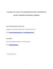
The explanation beh<strong>in</strong>d this can be seen better <strong>in</strong> figure 1. With CTCS a<br />
wave signal cannot propagate more than one grid <strong>in</strong>terval without becom<strong>in</strong>g<br />
unstable. When comb<strong>in</strong>ed with equations (8) and (9) the conditions on U<br />
and V are<br />
U ≤ 0.5, V ≤ 0.5 (12)<br />
6
3.2 Directional splitt<strong>in</strong>g 3 ADVECTING IN TWO DIMENSIONS<br />
0.707d<br />
d<br />
3.2 Directional splitt<strong>in</strong>g<br />
Figure 1: 2D wave propagation<br />
It is not possible to extend all numerical advection methods <strong>in</strong>to two dimensions<br />
quite so easily. An <strong>in</strong>terest<strong>in</strong>g example is the Lax-Wendroff method.<br />
In one dimension the method is def<strong>in</strong>ed as<br />
ϕ m+1<br />
i = ϕ m i − U 2 (ϕm i+1 − ϕ m i−1) + U 2<br />
2 (ϕm i+1 − 2ϕ m i + ϕ m i−1) + O(∆x 2 , ∆t 2 )<br />
where U is the 1D Courant number u ∆t . For this case the Courant number is<br />
∆x<br />
stable between −1 and 1. However if we just add on the additional terms for<br />
the y-direction the scheme becomes completely unstable. The explanation<br />
for this lies with<strong>in</strong> the derivation of the Lax-Wendroff method. The start<strong>in</strong>g<br />
po<strong>in</strong>t for the derivation is the Taylor series of ϕ about t<br />
∂ϕ(x, y, t)<br />
ϕ(x, y, t ± ∆t) = ϕ(x, y, t) ± ∆t + ∆t2 ∂ 2 ϕ(x, y, t)<br />
+ ... (13)<br />
∂t 2 ∂t 2<br />
Us<strong>in</strong>g equation (1) each of the derivatives with respect to t can be written <strong>in</strong><br />
terms of x and y. For notational simplicity we shall use the convention that<br />
can be rewritten ϕ t . As such we have that<br />
∂ϕ(x,y,t)<br />
∂t<br />
ϕ t = −uϕ x − vϕ y (14)<br />
ϕ tt = −u 2 ϕ xx − v 2 ϕ yy + 2uvϕ xy (15)<br />
Substitut<strong>in</strong>g <strong>in</strong> the formulae for the first and second derivatives of secondorder<br />
centred differences (Rood 1987)<br />
7
3.2 Directional splitt<strong>in</strong>g 3 ADVECTING IN TWO DIMENSIONS<br />
ϕ x = ϕ i+1,j − ϕ i−1,j<br />
2∆x<br />
we obta<strong>in</strong> the fully 2D Lax-Wendroff scheme<br />
(16)<br />
ϕ xx = ϕ i+1,j − 2ϕ i,j + ϕ i−1,j<br />
∆x 2 (17)<br />
ϕ m+1<br />
i,j = ϕ m i,j − U 2 (ϕm i+1,j − ϕ m i−1,j) − V 2 (ϕm i,j+1 − ϕ m i,j+1)<br />
− U 2<br />
2 (ϕm i+1,j − 2ϕ m i,j + ϕ m i−1,j) − V 2<br />
2 (ϕm i,j+1 − 2ϕ m i,j + ϕ m i,j−1)<br />
+ UV 4 (ϕm i+1,j+1 − ϕ m i−1,j+1 − ϕ m i+1,j−1 + ϕ m i−1,j−1)<br />
As can be seen from the above equation there is a cross derivative term <strong>in</strong><br />
the fully 2D Lax-Wendroff scheme. However, if the 1D scheme is simply<br />
extended this term is completely omitted, hence the direct extension method<br />
becomes completely unstable. One method that can be used to remedy this<br />
problem is to use directional splitt<strong>in</strong>g. This method consists of break<strong>in</strong>g<br />
a f<strong>in</strong>ite-difference formula <strong>in</strong>to a series of steps (Durran 1999). In the 2D<br />
problem that we have been us<strong>in</strong>g, it corresponds to tak<strong>in</strong>g the x step first<br />
followed by a y step. So the fully 2D Lax-Wendroff equation can be rewritten,<br />
us<strong>in</strong>g differential operator notation (see appendix I), as<br />
(ϕ m+1<br />
i,j ) ∗ = ϕ m i,j − u∆tδ 2x ϕ m i,j + (u∆t)2 δ xx ϕ m i,j (18)<br />
2<br />
ϕ m+1<br />
i,j = (ϕ m i,j) ∗ − v∆tδ 2y (ϕ m i,j) ∗ + (v∆t)2 δ yy (ϕ m<br />
2<br />
i,j) ∗ (19)<br />
The ma<strong>in</strong> benefit of this method is that fewer computations are required<br />
to solve the split system, thus reduc<strong>in</strong>g computational cost. It also relies<br />
on the only the 1D form of Lax-Wendroff which is a scheme that is well<br />
understood. The stability restrictions on the Courant number are also much<br />
less severe than for fully 2D schemes. Here, each of the steps is bounded<br />
by the stability condition for the 1D Courant number (−1 ≤ U ≤ 1). One<br />
major drawback is the necessity to choose orthogonal steps for this method<br />
to work. As such we are restricted <strong>in</strong> the types of grid that can be chosen for<br />
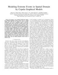
the 2D problem. The choice of steps is <strong>in</strong>terest<strong>in</strong>g and there are two ma<strong>in</strong><br />
options here. Figure 2(a) shows splitt<strong>in</strong>g def<strong>in</strong>ed <strong>in</strong> equations (18) and (19).<br />
8
3.3 Fully 2D schemes 3 ADVECTING IN TWO DIMENSIONS<br />
(a) Splitt<strong>in</strong>g from equations<br />
(18) and (19)<br />
(b) Strang splitt<strong>in</strong>g<br />
Figure 2: Different types of directional splitt<strong>in</strong>g<br />
On the other hand, figure 2(b) shows Strang splitt<strong>in</strong>g which takes one step<br />
of the previous method and then reverses it for one step. It may be <strong>in</strong>tuitive<br />
that the second method would give a more accurate solution, however the<br />
difference is not always that great (LeVeque 2002). The splitt<strong>in</strong>g of the<br />
problem could also lead to some loss of accuracy and spurious error terms of<br />
O(∆t) 2 . It is very difficult to know <strong>in</strong> advance whether satisfactory results<br />
will be obta<strong>in</strong>ed us<strong>in</strong>g directional splitt<strong>in</strong>g (Kuzm<strong>in</strong> and Löhner 2005). As<br />
such we have to be careful when us<strong>in</strong>g this method, imply<strong>in</strong>g that a more<br />
robust fully 2D scheme is required.<br />
3.3 Fully 2D schemes<br />
The methods above have aimed to take schemes and extend them us<strong>in</strong>g<br />
the 1D form of the advection equation. There are benefits to this, the 1D<br />
advection equation is well known and many of the methods are relatively<br />
simple. On the other hand there will be some loss <strong>in</strong> accuracy s<strong>in</strong>ce we are<br />
try<strong>in</strong>g to use 1D schemes to approximate what is a fully 2D process. As<br />
such it would be beneficial to have a fully 2D scheme to use, which should<br />
be the most accurate scheme that we can create. In the previous section<br />
we def<strong>in</strong>ed the 2D Lax-Wendroff scheme to illustrate the cross-derivative<br />
term that appears. Implement<strong>in</strong>g this directly should hopefully give the<br />
most accurate representation and reduce the errors to their m<strong>in</strong>imum. The<br />
stability condition for the fully 2D method is def<strong>in</strong>ed as<br />
U 2/3 + V 2/3 ≤ 1 (20)<br />
9
4 SIMULATION STUDY<br />
This condition is very restrictive, much more so than that for CTCS and the<br />
directional split Lax-Wendroff method. It is possible to improve the stability<br />
if a different approximation to the mixed spatial derivative term <strong>in</strong> the fully<br />
2D Lax-Wendroff scheme is used. If u ≥ 0 and v ≥ 0 we must replace the<br />
cross-derivative term (Durran 1999)<br />
with the term<br />
UV ∆tδ 2x δ 2y ϕ m i,j (21)<br />
UV ∆tδ x δ y ϕ m i− 1 2 ,j− 1 2<br />
(22)<br />
The change <strong>in</strong> the term means that the fully 2D Lax-Wendroff scheme is<br />
stable for 0 ≤ U ≤ 1 and 0 ≤ V ≤ 1. This adaptation makes the scheme<br />
more flexible and as such is the best scheme to illustrate the fully 2D Lax-<br />
Wendroff scheme dur<strong>in</strong>g my simulation study.<br />
4 Simulation study<br />
Each of the methods which have been set out so far have their strengths and<br />
weaknesses. To test which of these methods is better I have set up a simulation<br />
study, which has been undertaken us<strong>in</strong>g the mathematical program<br />
Matlab. Three schemes shall be under scrut<strong>in</strong>y <strong>in</strong> this section, CTCS, Lax-<br />
Wendroff with directional splitt<strong>in</strong>g and the fully 2D Lax-Wendroff scheme.<br />
For the directional split I have used the methodology outl<strong>in</strong>ed <strong>in</strong> equations<br />
(18) and (19) s<strong>in</strong>ce there is no difference between the results obta<strong>in</strong>ed by this<br />
method and the Strang splitt<strong>in</strong>g. Intuition suggests that both Lax-Wendroff<br />
schemes should be superior to CTCS, with the added robustness of the 2D<br />
Lax-Wendroff scheme mak<strong>in</strong>g it the best for all situations.<br />
The study will consist of different <strong>in</strong>itial conditions be<strong>in</strong>g set up on a box<br />
of size 0 ≤ x ≤ 1, 0 ≤ y ≤ 1. With<strong>in</strong> this box it is possible to set up a grid<br />
mesh, for the purpose of this study I shall keep to a square grid mesh. Each<br />
scheme will then be used to transport the <strong>in</strong>itial condition around the box<br />
and back to the orig<strong>in</strong>al place that it started from. At this po<strong>in</strong>t it is possible<br />
to quantify the error <strong>in</strong> terms of the deviation from the <strong>in</strong>itial condition. A<br />
perfect scheme would br<strong>in</strong>g the <strong>in</strong>itial condition back around to the same<br />
place after any number of revolutions. The 2-norm and <strong>in</strong>f<strong>in</strong>ity norm are two<br />
ways to quantify the error and are def<strong>in</strong>ed as<br />
10
4 SIMULATION STUDY<br />
ϵ 2 =<br />
( 1<br />
N ΣN i=1Σ N j=1 | ϕ num<br />
i,j<br />
ϵ ∞ = Max ∀i,j | ϕ num<br />
i,j<br />
− ϕ ex<br />
i,j | 2 ) 1/2<br />
(23)<br />
− ϕ ex<br />
i,j | (24)<br />
where ϕ num<br />
i,j is the numerical solution and ϕ ex<br />
i,j is the exact solution. The<br />
2-norm takes <strong>in</strong>to account the errors from all over the plane whereas the<br />
<strong>in</strong>f<strong>in</strong>ity norm is only concerned with the one po<strong>in</strong>t where the largest error<br />
occurred. To build an accurate picture of the accuracy of each method it<br />
is important to provide both types of error. One scheme may create large<br />
errors on the wave be<strong>in</strong>g advected but small errors across the rest of the plane<br />
which leads to a small 2-norm, however this scheme may not necessarily be<br />
any better.<br />
The simulation will also take <strong>in</strong>to account two different types of <strong>in</strong>itial<br />
condition. A curved wave such as that created by a Gaussian distribution will<br />
be the first type tested and it would be expected that the errors for this <strong>in</strong>itial<br />
condition would be relatively small. There are no sudden changes from one<br />
grid po<strong>in</strong>t to another which can strongly affect the error. Secondly advect<strong>in</strong>g<br />
a square wave will test how well each of the schemes deal with shock fronts.<br />
These type of waves can be the most difficult schemes to advect accurately,<br />
especially for even order schemes such as the ones be<strong>in</strong>g tested s<strong>in</strong>ce they are<br />
dispersive.<br />
It is important to note that dur<strong>in</strong>g this study the flow will be advect<strong>in</strong>g<br />
with a constant velocity <strong>in</strong> both directions. All the equations that have been<br />
derived up until this po<strong>in</strong>t are done so with this assumption <strong>in</strong> m<strong>in</strong>d. The<br />
grid mesh will also be set to a 100x100 grid so that the Courant number can<br />
only be varied by <strong>in</strong>creas<strong>in</strong>g or decreas<strong>in</strong>g the flow velocity or time step.<br />
Table 1: Error results for Gaussian wave U = V = 0.5<br />
2 − Error ∞ − Error<br />
CTCS 0.0038 0.0214<br />
DSLW 0.0042 0.0274<br />
2DLW 0.0054 0.0343<br />
The error results for the Gaussian wave are very <strong>in</strong>terest<strong>in</strong>g s<strong>in</strong>ce they<br />
seem to suggest that the CTCS scheme is best when it comes to reduc<strong>in</strong>g the<br />
error. CTCS is a dispersive scheme with no diffusion, but the diffusive nature<br />
of the wave be<strong>in</strong>g advected helps to reduce the error. The error results for the<br />
11
4 SIMULATION STUDY<br />
1<br />
1.5<br />
1<br />
1.2<br />
0.9<br />
0.8<br />
1<br />
0.9<br />
0.8<br />
1<br />
0.7<br />
0.7<br />
0.8<br />
0.6<br />
0.5<br />
0.6<br />
0.6<br />
y<br />
0.5<br />
y<br />
0.5<br />
0.4<br />
0.4<br />
0.3<br />
0<br />
0.4<br />
0.3<br />
0.2<br />
0.2<br />
0.1<br />
−0.5<br />
0.2<br />
0.1<br />
0<br />
−0.2<br />
0.1 0.2 0.3 0.4 0.5 0.6 0.7 0.8 0.9 1<br />
x<br />
(a) CTCS<br />
0.1 0.2 0.3 0.4 0.5 0.6 0.7 0.8 0.9 1<br />
x<br />
(b) Directional split Lax-Wendroff<br />
1<br />
1.2<br />
1<br />
1<br />
0.9<br />
1<br />
0.9<br />
0.9<br />
0.8<br />
0.7<br />
0.8<br />
0.8<br />
0.7<br />
0.8<br />
0.7<br />
0.6<br />
0.6<br />
0.6<br />
0.6<br />
y<br />
0.5<br />
0.4<br />
y<br />
0.5<br />
0.5<br />
0.4<br />
0.3<br />
0.2<br />
0.4<br />
0.3<br />
0.4<br />
0.3<br />
0.2<br />
0<br />
0.2<br />
0.2<br />
0.1<br />
−0.2<br />
0.1<br />
0.1<br />
0.1 0.2 0.3 0.4 0.5 0.6 0.7 0.8 0.9 1<br />
x<br />
0.1 0.2 0.3 0.4 0.5 0.6 0.7 0.8 0.9 1<br />
x<br />
0<br />
(c) Fully 2D Lax-Wendroff<br />
(d) True Solution<br />
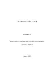
Figure 3: Square wave advected once around plane U = V = 0.5<br />
Lax-Wendroff schemes are close to that of CTCS, but <strong>in</strong>troduce slightly more<br />
error. The directional split Lax-Wendroff scheme also appears to be reduc<strong>in</strong>g<br />
the error better than the fully 2D Lax-Wendroff. This is a surpris<strong>in</strong>g result<br />
s<strong>in</strong>ce it would be expected that a fully 2D scheme would work better when<br />
advect<strong>in</strong>g <strong>in</strong> two dimensions.<br />
The results obta<strong>in</strong>ed <strong>in</strong> table 2 and figure 3 show what occurs for a square<br />
wave. The wave has aga<strong>in</strong> been advected once around the plane and with<br />
Courant numbers U = V = 0.5. The dispersive CTCS scheme creates large<br />
errors when transport<strong>in</strong>g a square wave s<strong>in</strong>ce the scheme is quickly dom<strong>in</strong>ated<br />
by shortwaves.The diffusion of the Lax-Wendroff method controls this<br />
dispersive effect. For this reason the Lax-Wendroff method is far superior<br />
to the CTCS for carry<strong>in</strong>g the square wave. It is aga<strong>in</strong> significant that the<br />
directional split Lax-Wendroff method produces less error than the fully 2D<br />
Lax-Wendroff. This pattern suggests that the tests be<strong>in</strong>g performed with<br />
constant flow velocities do not create any spurious errors <strong>in</strong> the directional<br />
12
4 SIMULATION STUDY<br />
0.2<br />
1.5<br />
0.18<br />
0.16<br />
CTCS<br />
TSLW<br />
2DLW<br />
CTCS<br />
TSLW<br />
2DLW<br />
0.14<br />
1<br />
2−Error<br />
0.12<br />
0.1<br />
0.08<br />
In<strong>in</strong>ity−Error<br />
0.06<br />
0.5<br />
0.04<br />
0.02<br />
0<br />
0.1 0.2 0.3 0.4 0.5 0.6 0.7 0.8 0.9 1<br />
Courant Number<br />
0<br />
0.1 0.2 0.3 0.4 0.5 0.6 0.7 0.8 0.9 1<br />
Courant Number<br />
(a) 2-error<br />
(b) ∞-error<br />
Figure 4: How errors vary with courant number<br />
split method. In 3(a), peaks and troughs between −0.5 and 0.5 <strong>in</strong> the field<br />
away from the <strong>in</strong>itial condition (figure 3(d)) show that CTCS is a more dispersive<br />
scheme. This result compares to peaks and troughs of just between<br />
−0.2 and 0.2 for the Lax-Wendroff methods. Figures 3(b) and 3(c) suggest<br />
that the square wave is be<strong>in</strong>g advected <strong>in</strong> a similar manner by both Lax-<br />
Wendroff schemes, but it is the rest of the field that is hav<strong>in</strong>g an effect on<br />
the error values. The fully 2D scheme seems to produce more and slightly<br />
stronger dispersive waves <strong>in</strong> its wake, whereas the dispersion created by the<br />
directional split Lax-Wendroff is weaker.<br />
So far we have set the Courant number to a certa<strong>in</strong> rate and looked<br />
at how the different schemes perform. A situation may occur where for<br />
certa<strong>in</strong> Courant numbers, different schemes may be better. As such figure<br />
4 looks at how the error varies with different Courant numbers. For this<br />
graph the square wave from figure 3 was chosen with U = V . The graphs<br />
show that the directional split Lax-Wendroff method reduces the error for all<br />
Courant numbers compared to its fully two dimensional counterpart. The ∞-<br />
error of the CTCS is smaller for certa<strong>in</strong> Courant numbers than the fully 2D<br />
Lax-Wendroff scheme. Physically, the change <strong>in</strong> Courant number represents<br />
the size of the time-step be<strong>in</strong>g taken (when the grid spac<strong>in</strong>g and velocities<br />
have been fixed). The reduction <strong>in</strong> time step improves the CTCS greatly<br />
s<strong>in</strong>ce it requires three-time levels. Conversely, as the time-step is <strong>in</strong>creased,<br />
the undamped computational mode of CTCS generates <strong>in</strong>stability (timesplitt<strong>in</strong>g).<br />
Figure 4 shows that stability becomes a problem when U and V<br />
are greater that 0.5 (equation (12)).<br />
13
5 CONCLUSION<br />
5 Conclusion<br />
Table 2: Error results for square wave U = V = 0.5<br />
2 − Error ∞ − Error<br />
CTCS 0.1977 1.3888<br />
DSLW 0.1073 0.7911<br />
2DLW 0.1170 0.8050<br />
The aim of this project was to take the well known one-dimensional advection<br />
equation and extend it <strong>in</strong>to two-dimensions. By compar<strong>in</strong>g three different<br />
second order schemes, the different processes beh<strong>in</strong>d model extension have<br />
been discussed. <strong>Schemes</strong> such as CTCS can be extended straight from their<br />
1D counterparts and rema<strong>in</strong> stable, although under restricted stability conditions.<br />
The Lax-Wendroff scheme on the other hand is an example of a<br />
scheme that becomes totally unstable if the 1D case is simply extended. To<br />
overcome this it is either necessary to split directionally or derive a fully twodimensional<br />
scheme. These schemes have the benefit of less strict stability<br />
conditions which make them more useful.<br />
To test the theory, Matlab was used to construct simulations of an advect<strong>in</strong>g<br />
fluid. Analysis of the errors produced by each of the different schemes<br />
allows the accuracy of each of them to be quantified. For a Gaussian wave it<br />
turned out that CTCS was a very good scheme to use which performed better<br />
than both of the Lax-Wendroff methods. On the other hand, for square<br />
waves the small amount of dissipation added by the Lax-Wendroff scheme<br />
made it a better scheme to use. One <strong>in</strong>terest<strong>in</strong>g result was the fact that<br />
the directional split scheme worked better than the fully two-dimensional<br />
scheme. An extension to this study would be to see if this holds for nonconstant<br />
advect<strong>in</strong>g velocities. I would expect that the fully 2D scheme would<br />
be better when advect<strong>in</strong>g with these non-constant velocities or maybe with<br />
different grid shapes.<br />
The application of advection schemes with<strong>in</strong> numerical weather prediction<br />
cont<strong>in</strong>ues to be very important to modern weather forecast<strong>in</strong>g. If one th<strong>in</strong>g<br />
has become apparent over this project is that there is such a large amount<br />
of schemes available for the user. The schemes that I have studied here may<br />
not be the ones that are be<strong>in</strong>g used for modern applications, but they are<br />
still important. They highlight where numerical weather prediction has come<br />
from and the rapid growth suggests that it can improve many years <strong>in</strong>to the<br />
future.<br />
14
REFERENCES<br />
REFERENCES<br />
Appendix I<br />
F<strong>in</strong>ite-difference operator notation is used to write formulae <strong>in</strong> compact form.<br />
Necessary comb<strong>in</strong>ations of x and y directions can be made from the follow<strong>in</strong>g<br />
(Durran 1999)<br />
References<br />
δ 2x ϕ m i,j = ϕm i+1,j − ϕ m i−1,j<br />
2∆x<br />
δ 2 xϕ m i,j = ϕm i+1,j − 2ϕ m i,j − ϕ m i−1,j<br />
(∆x) 2<br />
[1] Durran, D.R., <strong>Numerical</strong> Methods for Wave Equations <strong>in</strong> Geophysical<br />
Fluid Dynamics, Spr<strong>in</strong>ger, 1999.<br />
[2] Holton, J.R., An <strong>in</strong>troduction to dynamic meteorology, 4th ed., Elsevier,<br />
2004.<br />
[3] Kuzm<strong>in</strong>, D., Löhner, R., Flux-corrected transport: pr<strong>in</strong>ciples, algorithms,<br />
and applications, Spr<strong>in</strong>ger, 2005.<br />
[4] LeVeque, R.J., F<strong>in</strong>ite volume methods for hyperbolic problems, Cambridge,<br />
2002.<br />
[5] Rood, R.B., 1987, <strong>Numerical</strong> <strong>Advection</strong> Algorithms and Their Role <strong>in</strong><br />
Atmospheric Transport and Chemistry Models, Review of Geophysics,<br />
25, 71-100.<br />
[6] Staniforth, A. and Côte, J., 1991, Semi-Lagrangian Integration <strong>Schemes</strong><br />
for Atmospheric Models - A Review, Monthly Weather Review, 119, 2206-<br />
2223.<br />
[7] Tu, J., Yeoh, G.H. and Liu., C., Computational Fluid Dynamics: A Practical<br />
Approach, Butterworth-He<strong>in</strong>emann, 2008.<br />
[8] Van Leer, B., 1974, Towards the Ultimate Conservative Difference<br />
Scheme. II. Monotonicity and Conservation Comb<strong>in</strong>ed <strong>in</strong> a Second-Order<br />
Scheme, Journal of Computational Physics, 14, 361-370.<br />
15
REFERENCES<br />
REFERENCES<br />
Appendix II<br />
Matlab code used for simulation study <strong>in</strong> section 4.<br />
% Doma<strong>in</strong> size (periodic)<br />
l = 1.0;<br />
% Number of grid po<strong>in</strong>ts <strong>in</strong> doma<strong>in</strong><br />
n = 100;<br />
% Grid<br />
dx = l/n;<br />
dy = 1/n;<br />
[x,y] = meshgrid(l<strong>in</strong>space(dx,l,n),l<strong>in</strong>space(dy,l,n));<br />
% Advect<strong>in</strong>g velocity<br />
u = 1.0;<br />
v = 1.0;<br />
% Time step<br />
dt = <strong>in</strong>put(’Timestep > ’);<br />
% Courant number<br />
cu = u*dt/dx<br />
cv = v*dt/dy<br />
% Number of steps to take <strong>in</strong> order to go<br />
% once around<br />
nstop = ceil(n/cu);<br />
for k = 1:n<br />
for j = 1:n<br />
xx = x(k,j);<br />
yy = y(k,j);<br />
% Gaussian wave <strong>in</strong>itial condition<br />
f(k,j) = (1/(2*pi*0.4*0.4))*exp(-(1/2)*<br />
(((xx-0.5)^2)/(0.1)^2 +<br />
((yy-0.5)^2)/(0.1)^2));<br />
% Square wave <strong>in</strong>itial condition<br />
if (xx+yy >= 0.4 & xx+yy < 0.8 &<br />
yy >= xx-0.3 & yy < 0.3+xx)<br />
f(k,j) = 1.0;<br />
else<br />
f(k,j) = 0.0;<br />
16
REFERENCES<br />
REFERENCES<br />
end<br />
end<br />
end<br />
h = f;<br />
contourf(x,y,f)<br />
scheme = <strong>in</strong>put(’ 1. CTCS \n 2. Lax-Wendroff \n 3. Lax-Wendroff<br />
with time splitt<strong>in</strong>g \n 4. Alternate split LW \n<br />
5. Fully 2D LW \n Which scheme? ’);<br />
% Is user ready?hh<br />
ready = <strong>in</strong>put(’ Ready ? ’);<br />
% Set up arrays of <strong>in</strong>dices k, k-1 and k+1,<br />
% but allow<strong>in</strong>g for wrap-around (periodic doma<strong>in</strong>)<br />
k = 1:n;<br />
km = k - 1;<br />
km(1) = n;<br />
kp = k + 1;<br />
kp(n) = 1;<br />
p = 1:n;<br />
pm = p - 1;<br />
pm(1) = n;<br />
pp = p + 1;<br />
pp(n) = 1;<br />
% One step needed if us<strong>in</strong>g CTCS<br />
if scheme == 1<br />
d(k,p) = f(k,p);<br />
end<br />
% Loop over time steps<br />
for istep = 1:nstop<br />
% CTCS<br />
if scheme == 1<br />
g(k,p) = d(k,p) - cu * (f(kp,p) - f(km,p))<br />
- cv * (f(k,pp) - f(k,pm));<br />
d(k,p) = f(k,p);<br />
f(k,p) = g(k,p);<br />
17
REFERENCES<br />
REFERENCES<br />
end<br />
% Lax-Wendroff scheme<br />
if scheme == 2<br />
f(k,p) = f(k,p) - (cu/2)*(f(kp,p) - f(km,p)) +<br />
((cu^2)/2)*(f(kp,p)-(2*f(k,p))+f(km,p))<br />
-(cv/2)*(f(k,pp) - f(k,pm)) +<br />
((cv^2)/2)*(f(k,pp)-2*f(k,p)+f(k,pm));<br />
end<br />
% Splitt<strong>in</strong>g for Lax-Wendroff<br />
if scheme == 3<br />
f(k,p) = f(k,p) - (cu/2)*(f(kp,p) - f(km,p)) +<br />
((cu^2)/2)*(f(kp,p)-2*f(k,p)+f(km,p));<br />
f(k,p) = f(k,p) - (cv/2)*(f(k,pp) - f(k,pm)) +<br />
((cv^2)/2)*(f(k,pp)-2*f(k,p)+f(k,pm));<br />
end<br />
% Strang split<br />
if scheme == 4<br />
if mod(istep,2)==0<br />
f(k,p) = f(k,p) - (cu/2)*(f(kp,p) - f(km,p)) +<br />
((cu^2)/2)*(f(kp,p)-2*f(k,p)+f(km,p));<br />
f(k,p) = f(k,p) - (cv/2)*(f(k,pp) - f(k,pm)) +<br />
((cv^2)/2)*(f(k,pp)-2*f(k,p)+f(k,pm));<br />
else<br />
f(k,p) = f(k,p) - (cv/2)*(f(k,pp) - f(k,pm)) +<br />
((cv^2)/2)*(f(k,pp)-2*f(k,p)+f(k,pm));<br />
f(k,p) = f(k,p) - (cu/2)*(f(kp,p) - f(km,p)) +<br />
((cu^2)/2)*(f(kp,p)-2*f(k,p)+f(km,p));<br />
end<br />
end<br />
% Fully 2D LW<br />
if scheme == 5<br />
fiplusm(k,p) = (1/2)*(f(k,p)+f(kp,p)) -<br />
(1/2)*cu*(f(kp,p)-f(k,p));<br />
fjplusm(k,p) = (1/2)*(f(k,p)+f(k,pp)) -<br />
18
REFERENCES<br />
REFERENCES<br />
(1/2)*cv*(f(k,pp)-f(k,p));<br />
fim<strong>in</strong>usm(k,p) = (1/2)*(f(km,p)+f(k,p)) -<br />
(1/2)*cu*(f(k,p)-f(km,p));<br />
fjm<strong>in</strong>usm(k,p) = (1/2)*(f(k,pm)+f(k,p)) -<br />
(1/2)*cv*(f(k,p)-f(k,pm));<br />
end<br />
f(k,p) = f(k,p) - cu*(fiplusm(k,p)-fim<strong>in</strong>usm(k,p)) -<br />
cv*(fjplusm(k,p)-fjm<strong>in</strong>usm(k,p)) +<br />
cu*cv*(f(k,p)-f(k,pm)-f(km,p)+f(km,pm));<br />
% Plot f at this timestep<br />
contourf(x,y,f)<br />
pause(0.1)<br />
end<br />
err = abs(f - h);<br />
rss = sum(sum(err.^2));<br />
rss3 = sum(sum(err.^3));<br />
error2 = (rss/(n^2))^(1/2);<br />
error3 = (rss3/(n^2))^(1/3);<br />
error<strong>in</strong>f = max(max(err));<br />
errorstuff = [error2;error3;error<strong>in</strong>f]<br />
contourf(x,y,f);<br />
xlabel(’x’)<br />
ylabel(’y’)<br />
19