Torque Limiters, Safety Couplings, Overload ... - ENEMAC GmbH
Torque Limiters, Safety Couplings, Overload ... - ENEMAC GmbH
Torque Limiters, Safety Couplings, Overload ... - ENEMAC GmbH

You also want an ePaper? Increase the reach of your titles
YUMPU automatically turns print PDFs into web optimized ePapers that Google loves.
Tel. +49 6022 71070<br />
JAKOB<br />
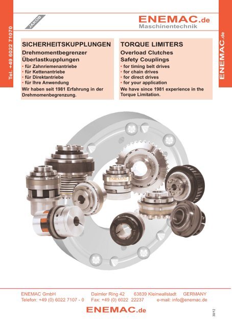
SICHERHEITSKUPPLUNGEN<br />
Drehmomentbegrenzer<br />
Überlastkupplungen<br />
• für Zahnriemenantriebe<br />
• für Kettenantriebe<br />
• für Direktantriebe<br />
• für Ihre Anwendung<br />
Wir haben seit 1981 Erfahrung in der<br />
Drehmomenbegrenzung.<br />
<strong>ENEMAC</strong>.de<br />
Maschinentechnik<br />
<strong>ENEMAC</strong> <strong>GmbH</strong> Daimler Ring 42 63839 Kleinwallstadt GERMANY<br />
Telefon: +49 (0) 6022 7107 - 0 Fax: +49 (0) 6022 22237 e-mail: info@enemac.de<br />
<strong>ENEMAC</strong>.de<br />
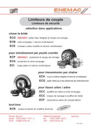
TORQUE LIMITERS<br />
<strong>Overload</strong> Clutches<br />
<strong>Safety</strong> <strong>Couplings</strong><br />
• for timing belt drives<br />
• for chain drives<br />
• for direct drives<br />
• for your application<br />
We have since 1981 experience in the<br />
<strong>Torque</strong> Limitation.<br />
30/12<br />
<strong>ENEMAC</strong>.de
Tel. +49 6022 71070<br />
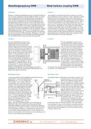
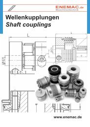
Sicherheitskupplungen Auswahl <strong>Torque</strong> <strong>Limiters</strong> selection<br />
Das <strong>ENEMAC</strong>-Baukastensystem ermöglicht für nahezu<br />
jeden Einsatzfall eine Lösung.<br />
indirekte Antriebe / indirect drives<br />
An die Sicherheitskupplung können verschiedene<br />
Anbauelemente wie Kettenräder oder Zahnscheiben befestigt<br />
werden, für Zahnriemenantriebe, Kettenantriebe.<br />
To the <strong>Torque</strong> Limiter optionally, various mounting elements<br />
are fixed, e.g. belt pulleys or sprockets for toothed belt<br />
drives, chaine drives.<br />
Passfedernut<br />
keyway<br />
ECE<br />
ECG<br />
ECH<br />
Drehmoment<br />
torque<br />
Durchmesser<br />
diameter<br />
schmale Anbauteile<br />
small attachments<br />
Klemmung<br />
clamping<br />
Konus<br />
conical<br />
Klemmnabe<br />
clamping hub<br />
ECB ECP<br />
Typ / type ECP<br />
Typ / type ECPB<br />
Passfedernut<br />
keyway<br />
ECU<br />
ECA<br />
ECR<br />
Passfedernut<br />
keyway<br />
9550 x P x K (kW)<br />
TK (Nm) =<br />
n (min-1 )<br />
Einbaumaße<br />
mounting dimensions<br />
normale Anbauteile<br />
normally attachments<br />
Klemmung<br />
clamping<br />
Konus<br />
conical<br />
direkte Antriebe / direct drives<br />
Klemmnabe<br />
clamping hub<br />
Passfedernut<br />
keyway<br />
breite Anbauteile<br />
wide attachments<br />
Klemmung<br />
clamping<br />
Klemmnabe<br />
clamping hub<br />
ECK<br />
ECA ECP ECI ECOL<br />
mit Metallbalg<br />
with bellow<br />
Klemmung<br />
clamping<br />
Konus<br />
conical<br />
ECU ECKH<br />
The <strong>ENEMAC</strong>-modular system offers different solutions for<br />
specific requirements.<br />
Bei direkten Antrieben werden zum Ausgleich von<br />
Wellenversätzen die Sicherheitskupplungen mit einem<br />
Metallbalg- oder Elastomerkupplungsteil ergänzt.<br />
For direct drives the <strong>Torque</strong> <strong>Limiters</strong> can be attached a<br />
metal bellow or elastomer coupling to compensate the<br />
shaft misalignment.<br />
Klemmnabe<br />
clamping hub<br />
ECPB<br />
ECPH<br />
T A > T K (Nm)<br />
Passfedernut<br />
keyway<br />
ECUD<br />
mit Elastomer<br />
with elastomer<br />
Klemmung<br />
clamping<br />
Konus<br />
conical<br />
Klemmnabe<br />
clamping hub<br />
ECKE<br />
ECPE ECPD<br />
P = Motorleistung / motor output<br />
n = Motordrehzahl / motor speed<br />
K = Stoßfaktor / drive factor<br />
ca. / approx. 1.1 - 1.4<br />
T K = Moment Kupplung / torque coupling<br />
T A = Ausrückmoment / disengagement torque<br />
Type ECR ist eine Edelstahl-Version<br />
type ECR is a stainless teel version<br />
Für weitere Fragen rufen Sie uns an oder senden ein E-Mail an: info@enemac.de<br />
For more information call us or send an e-mail to: sales@enemac.de<br />
30/12<br />
<strong>ENEMAC</strong>.de
<strong>ENEMAC</strong> <strong>Torque</strong> <strong>Limiters</strong> are the life insurance for your machines,<br />
no matter whether the error is due to incorrect operation, programming error, material<br />
overload or tool breakage. The couplings reduce expensive machine damages, repairs<br />
and down time by acting as torque limiters and overload protection, absolutely reliably.<br />
Our <strong>Torque</strong> <strong>Limiters</strong> are the result of decades of continuous research and development<br />
as well as the experience gained from thousands of different applications worldwide.<br />
<strong>Torque</strong> <strong>Limiters</strong> for toothed belt and chain drives<br />
type ECOL<br />
• with slide, integrated bearing<br />
• low cost standard version<br />
• with radial clamping hub for simple<br />
installation<br />
• with small centric diameter for<br />
attachement small size parts<br />
type ECP<br />
• with integral ball bearing<br />
• with radial clamping hub for simple<br />
installation<br />
• true-running accuracy<br />
• for high radial and axial load<br />
• for large shaftdiameter<br />
characteristics:<br />
• optimum overload and crash protection<br />
• backlash free torque transfer<br />
• stepless disengagement torque adjustment<br />
• fixed point reengagement (360° synchroni<br />
sed position)<br />
• automatic re-engaging<br />
• degressive spring characteristic<br />
• excellent dynamic functional characteristics<br />
• large selection of types (modular system)<br />
• compensation of shaft misalignments<br />
• integral fitting of pulleys<br />
proximity switch <strong>Torque</strong> Limiter ECP<br />
Tel: + 49 (0) 6022 7107-0 Fax: + 49 (0) 6022 22237<br />
toothed belt drive<br />
KW: 30/09
<strong>Torque</strong> Limiter type ECP<br />
with integrated ball bearing<br />
simple installation with clamping hub<br />
for high radial load, compact performance<br />
optional corrosion protected<br />
technical data:<br />
ECP<br />
disengament moment mass tightening torque max. radial bore diameters ØD<br />
torque TA [Nm]<br />
<br />
of inertia<br />
[10<br />
approx. of screw “ i ” load<br />
-3kgm2 ] [kg] [Nm] FR [N]<br />
prebored min max<br />
25 - 6 * 3,6 - 6 6 / 16<br />
0,09 0,36 M 5 / [10] 5.000 6<br />
25 - 12 7 - 12<br />
8 / 16<br />
35 - 15 * 8 - 15 10 / 25,4<br />
35 - 30 13 - 30 0,36 0,80 M 6 / [18] 8.000 10 12 / 25,4<br />
35 - 45 22 - 45 14 / 25,4<br />
46 - 60 * 25 - 60 18 / 35<br />
46 - 100 40 - 100 1,10 1,50 M 8 / [40] 9.500 17 18 / 35<br />
46 - 150 60 - 150 24 / 35<br />
65 - 230 * 80 - 230 24 / 44<br />
4,20 3,30 M10 / [80] 23.000 21<br />
65 - 330 130 - 330<br />
32 / 44<br />
80 - 500 200 - 500 28 / 58<br />
12,20 6,20 M14 / [220] 30.000 27<br />
80 - 800 350 - 800<br />
40 / 58<br />
115 - 1000 500 - 1000 42 / 100<br />
115 - 2000 800 - 2000 76 20 2x M16 / [290] 50.000 38 48 / 100<br />
115 - 3000 1500 - 3000 60 / 100<br />
the disengagement torque TA is continuously adjustable, unless otherwise spezified by the customer, TA is preset to TA max. !<br />
* smaller torque range possible on request<br />
s switching distance<br />
^ 0,03 A FR<br />
material: heat-treated steel<br />
dimensions: (mm) length dimensions according to DIN ISO 2768 mH<br />
Om -0,1<br />
* note: smaller outer diameters of the switch plate are possible (see values in brackets)<br />
ordering example: ECP 35-30 D = 24 H7 TA = 25Nm<br />
ECP 46-100 KS D = 30 H7 TA = 100Nm (corrosion protected)<br />
Op<br />
n<br />
Okh5<br />
OD<br />
-A-<br />
g<br />
t<br />
f<br />
La<br />
e<br />
w<br />
h<br />
OD2<br />
c<br />
Oa<br />
i - ISO 4762<br />
ECP Øa (Øa*) Ø b c e f g h Ø k h5 Øm Øp La n s t w<br />
25 - 6/12 48 (42) 38,5 13,5 13 8 9,8 6 42 52 47 41 6xM3 0,9 7 15,8<br />
35 - 15/30/45 66 (60) 53 19,5 15 9 11,5 7,5 55 69 62 48 6xM4 1,2 8 18,5<br />
46 - 60/100/150 83 (76) 68 25,5 18,5 9 12 8,5 68 87 78 55,5 6xM6 1,6 8 22,4<br />
65 - 230 /330 109 (104) 87 32 21 14 16,5 10,5 90 113 102 71,5 6xM8 1,8 12 25,6<br />
80 - 500/800 132 - 115 42 30 15 17 13,5 110 136 124 87,5 8xM8 2,5 12 37<br />
115 - 1000-3000 185 - 172 69 76 16 28 17/30 140 181 165 142±2 12xM10 3,7 22,5 77<br />
<strong>ENEMAC</strong>.de<br />
sales@enemac.de Tel: +49 (0) 6022 7107-0 Fax: +49 (0) 6022 22237<br />
KW: 24/12
<strong>Torque</strong> Limiter type ECK<br />
with integrated ball bearing<br />
simple installation with conical hub<br />
for high radial load, compact performance<br />
technical data:<br />
ECK<br />
disengagement moment mass tightening torque max. radial bore diameters ØD<br />
torque TA [Nm]<br />
< setting range ><br />
of inertia<br />
[10<br />
approx. of screw load<br />
-3kgm2 ] [kg] 6x “i” - [Nm] FR [N]<br />
prebored min max<br />
25 - 6<br />
25 - 12<br />
* 3,6<br />
7<br />
-<br />
-<br />
6<br />
12<br />
0,08 0,3 M3 - ISO 4762 - [2] 5.000 -<br />
5<br />
5<br />
/<br />
/<br />
12<br />
12<br />
35 - 15 * 8 - 15 9 / 17<br />
35 - 30 13 - 30 0,31 0,65 M4 - ISO 4762 - [4] 8.000 8 9 / 17<br />
35 - 45 22 - 45 10 / 17<br />
46 - 60 * 25 - 60 12 / 24<br />
46 - 100 40 - 100 0,95 1,3 M6 - ISO 4017 - [14] 9.500 11 12 / 24<br />
46 - 150 60 - 150 14 / 24<br />
65 - 230<br />
65 - 330<br />
* 80<br />
130<br />
-<br />
-<br />
230<br />
330<br />
3,8 2,9 M6 - ISO 4017 - [14] 23.000 17<br />
18<br />
22<br />
/<br />
/<br />
35<br />
35<br />
80 - 500<br />
80 - 800<br />
200<br />
350<br />
-<br />
-<br />
500<br />
800<br />
10 5,1 M8 - ISO 4017 - [35] 30.000 25<br />
28<br />
30<br />
/<br />
/<br />
44<br />
44<br />
115 - 1000 500 - 1000 40 / 62<br />
115 - 2000 800 - 2000 53 14 M12 - ISO 4017 - [115] 50.000 38 42 / 62<br />
115 - 3000 1500 - 3000 48 / 62<br />
the disengagement torque TA is continuously adjustable, unless otherwise spezified by the customer, TA is preset to TA max. !<br />
* smaller torque range possible on request<br />
material: heat-treated steel<br />
-0,1<br />
Øm<br />
O p<br />
n<br />
^ 0,03 A<br />
dimensions: (mm) length dimensions according to DIN ISO 2768 mH<br />
* note: smaller outer diameters of the switch plate are possible (see values in brackets)<br />
ordering example: ECK 35-30 D = 24 H7 TA = 25Nm<br />
Økh5<br />
g<br />
FR<br />
t f<br />
s<br />
La<br />
switching distance<br />
ECK Ø a (Ø a*) Ø b Ø c e f g Ø k h5 Øm Øp La n s t w<br />
25 - 6/12 48 (42) 33 19 15 8 9,8 42 52 47 39 6xM3 0,9 7 13,8<br />
35 - 15/30/45 66 (60) 45 27 18 9 11,5 55 69 62 47,5 6xM4 1,2 8 18,1<br />
46 - 60/100/150 83 (76) 63 36 24 9 12 68 87 78 55,5 6xM6 1,6 8 22,4<br />
65 - 230 /330 109 (104) 84 50 27 14 16,5 90 113 102 70 6xM8 1,8 12 24<br />
80 - 500/800 132 - 105 62 32 15 17 110 136 124 84 8xM8 2,5 12 33,4<br />
115 - 1000-3000 185 - 168 90 45 16 28 140 181 165 130 12xM10 3,7 22,5 64,5<br />
<strong>ENEMAC</strong>.de<br />
e<br />
w<br />
ØD<br />
A<br />
Øc<br />
Tel: + 49 (0) 6022 7107-0 Fax: + 49 (0) 6022 22237<br />
KW: 11/12<br />
Øb<br />
Øa
<strong>Torque</strong> Limiter type ECU<br />
with integrated ball bearing<br />
simple installation with keyway<br />
for high radial load, compact performance<br />
technical data:<br />
ECU<br />
disengagement moment mass max. radial bore diameters ØD<br />
torque TA [Nm]<br />
< setting range ><br />
of inertia<br />
[10<br />
approx. load<br />
-3kgm2 ] [kg] FR [N]<br />
min max<br />
25 - 6<br />
25 - 12<br />
* 3,6<br />
7<br />
-<br />
-<br />
6<br />
12<br />
0,08 0,28 5.000<br />
6<br />
6<br />
/<br />
/<br />
13<br />
13<br />
35 - 15 * 8 - 15 8 / 22<br />
35 - 30 13 - 30 0,3 0,63 8.000 10 / 22<br />
35 - 45 22 - 45 10 / 22<br />
46 - 60 * 25 - 60 11 / 34<br />
46 - 100 40 - 100 0,91 1,25 9.500 13 / 34<br />
46 - 150 60 - 150 16 / 34<br />
65 - 230<br />
65 - 330<br />
* 80<br />
130<br />
-<br />
-<br />
230<br />
330<br />
3,7 2,8 23.000<br />
18<br />
21<br />
/<br />
/<br />
38<br />
38<br />
80 - 500<br />
80 - 800<br />
200<br />
350<br />
-<br />
-<br />
500<br />
800<br />
9,25 4,8 30.000<br />
26<br />
38<br />
/<br />
/<br />
55<br />
55<br />
115 - 1000 500 - 1000 39 / 90<br />
115 - 2000 800 - 2000 52 15,5 50.000 52 / 90<br />
115 - 3000 1500 - 3000 66 / 90<br />
Øm-0,1<br />
O p<br />
n<br />
^ 0,03 A<br />
dimensions: (mm) length dimensions according to DIN ISO 2768 mH<br />
h5<br />
Øk<br />
g<br />
FR<br />
t f<br />
Tel: + 49 (0) 6022 7107-0 Fax: + 49 (0) 6022 22237<br />
La<br />
s<br />
switching distance<br />
ECU Øa (Øa*) Ø b f g Ø k h5 Øm Øp La n s t w<br />
25 - 6/12 48 (42) 33 8,5 9,8 42 52 47 31 6xM3 0,9 7 5,8<br />
35 - 15/30/45 66 (60) 45 9,3 11,5 55 69 62 38 6xM4 1,2 8 8,6<br />
46 - 60/100/150 83 (76) 63 9,8 12 68 87 78 44,5 6xM6 1,6 8 11,4<br />
65 - 230 /330 109 (104) 84 14,8 16,5 90 113 102 59,5 6xM8 1,8 12 13,7<br />
80 - 500/800 132 - 105 15,7 17 110 136 124 68,5 8xM8 2,5 12 18,1<br />
115 - 1000-3000 185 - 168 19 28 140 181 165 106 12xM10 3,7 22,5 40,4<br />
* note: smaller outer diameters of the switch plate are possible (see values in brackets)<br />
ordering example: ECU 35-30 D = 22 H7 with keyway 6 P9 TA = 25Nm<br />
w<br />
NEW!<br />
the disengagement torque TA is continuously adjustable, unless otherwise spezified by the customer, TA is preset to TA max. !<br />
* smaller torque range possible on request<br />
material: heat-treated steel<br />
A<br />
OD<br />
Øb<br />
Øa<br />
KW: 28/09
<strong>Torque</strong> Limiter type ECOL<br />
with radial clamping hub for simple installation<br />
with longer bearing journal for integrated slide bearing<br />
with small centric diameter for attachment of small size pulleys, gear wheels, sprockets<br />
technical data:<br />
ECOL<br />
disengament<br />
torque TA [Nm]<br />
< setting range ><br />
moment<br />
of inertia<br />
[10<br />
mass<br />
approx.<br />
tightening torque<br />
of screw “ i ”<br />
borediameters ØD<br />
-3kgm2 ] [kg] [Nm]<br />
prebored min. max<br />
25 - 6<br />
25 - 12<br />
* 3,6<br />
7<br />
-<br />
-<br />
6<br />
12<br />
0,05 0,25 M 5 / 10 6<br />
6<br />
8<br />
/<br />
/<br />
16<br />
16<br />
35 - 15 * 8 - 15 10 / 25,4<br />
35 - 30 13 - 30 0,25 0,65 M 6 / 18 10 12 / 25,4<br />
35 - 45 22 - 45 14 / 25,4<br />
46 - 60 25 - 60 18 / 35<br />
46 - 100 40 - 100 0,95 1,5 M 8 / 40 17 18 / 35<br />
46 - 150 60 - 150 24 / 35<br />
65 - 230<br />
65 - 330<br />
80<br />
130<br />
-<br />
-<br />
230<br />
330<br />
3,34 3 M 10 / 80 21<br />
24<br />
32<br />
/<br />
/<br />
42<br />
42<br />
80 - 500<br />
80 - 800<br />
200<br />
350<br />
-<br />
-<br />
500<br />
800<br />
10,70 6 M 14 / 220 27<br />
28<br />
40<br />
/<br />
/<br />
58<br />
58<br />
the disengagement torque TA is continuously adjustable, unless otherwise spezified by the customer, TA is preset to TA max. !<br />
* smaller torque range possible on request<br />
f s<br />
switching distance<br />
material: heat treated steel<br />
Ok<br />
a 0,02 A<br />
Op<br />
Omh6<br />
OD<br />
dimensions: (mm) length dimensions according to DIN ISO 2768 mH<br />
* note: bigger outer diameters of the switch plate are available if required<br />
** alternative bearing length are possible on request<br />
ordering example: ECOL 46-150 - D = 28 H7 - TA = 120 Nm<br />
-A-<br />
n<br />
g<br />
La<br />
e<br />
w<br />
h<br />
c<br />
Ob<br />
Oa<br />
i-DIN912<br />
ECOL Øa (Øa*) Ø b c e f g** h Ø k Ø m h6 Ø p La 6x n s w<br />
25 - 6/12 42 (48) 38,5 13,5 13 5 11 6 40 20 32 41 M 3 0,9 15,8<br />
35 - 15/30/45 60 (66) 53 19,5 15 7 15 7,5 58 30 46 52 M 4 1,2 18,6<br />
46 - 60/100/150 76 (83) 68 25,5 18,5 9 20 8,5 75 42 62 69 M 6 1,6 22,4<br />
65 - 230/330 104 (109) 87 32 21 12 25 10,5 98 50 74 84 M 8 1,8 26,7<br />
80 - 500/800 132 - 115 42 30 14 30 13,5 120 65 92 104 M 10 2,5 37<br />
<strong>ENEMAC</strong>.de<br />
info@enemac.de Tel: +49 6022 7107-0 Fax: +49 6022 22237<br />
29/12
<strong>Torque</strong> Limiter type ECPB<br />
for shaft- to shaft-connections, with bellow attachment<br />
with radial clamping hub on both sides, simple installation<br />
compensation of misalignments, low restoring forces<br />
technical data:<br />
disengagement moment mass torsional max. shaft tightening Ø D1 Ø D2<br />
ECPB torque TA [Nm] of inertia approx. stiffness displacement [mm] torque of screws<br />
< setting range > [10-3kgm2 min max min max<br />
] [kg] [Nm/arcmin] axial ± lateral “f”[Nm] “i”[Nm]<br />
25 - 6<br />
25 - 12<br />
* 3,6 -<br />
7 -<br />
6<br />
12<br />
0,13 0,45 2,6 0,4 0,15 M 5 [ 7] M 5 [10]<br />
6<br />
8<br />
19/24<br />
19/24<br />
6<br />
8<br />
16<br />
16<br />
35 - 15 * 8 - 15 9 30 10 25,4<br />
35 - 30 13 - 30 0,5 1 9 0,5 0,2 M 6 [14] M 6 [18] 12 30 12 25,4<br />
35 - 45 22 - 45 16 30 14 25,4<br />
46 - 60 25 - 60 15 38 18 35<br />
46 - 100 40 - 100 1,5 1,9 20 0,6 0,2 M 8 [35] M 8 [40] 20 38 18 35<br />
46 - 150 60 - 150 25 38 24 35<br />
65 - 230<br />
65 - 330<br />
80 - 230<br />
130 - 330<br />
5,5 3,8 28 0,8 0,2 M10 [ 65] M10 [ 80]<br />
25<br />
32<br />
43<br />
43<br />
24<br />
32<br />
44<br />
44<br />
80 - 500 200 - 500 14 6,8 52 0,8 0,2 M12 [115] M14 [220] 35 55 28 58<br />
80 - 800 350 - 800 16 7,2 106 0,7 0,2 M14 [200] M14 [220] 42 70 40 58<br />
115 - 1000 500 - 1000 80 21,5 80 1 0,3 M14 [185] 2xM16 [290] 40 75 42 100<br />
115 - 2000 800 - 2000 90 22,5 140 1 0,3 M16 [290] 2xM16 [290] 45 85 45 100<br />
115 - 3000 1500 - 3000 111 30 280 1,3 0,2 4xM16 [290] 2xM16 [290] 60 88 60 100<br />
the disengagement torque TA is continuously adjustable, unless otherwise spezified by the customer, TA is preset to TA max. !<br />
* smaller torque range possible on request<br />
s feed motion<br />
material:<br />
- safety part: heat treated steel<br />
- clamping hub: high tensile aluminium<br />
- bellows: stainless steel<br />
- screws: nickel plated<br />
dimensions: (mm) length according to DIN ISO 2768 mH<br />
Oa<br />
Ob<br />
g1<br />
OD1<br />
t1<br />
h1 h2<br />
f-ISO4762 k<br />
w i-ISO4762<br />
ECPB Ø a Ø b Ø c e g1 g2 h1 h2 k * L±1 s t1 t2 w<br />
25 - 6 / 12 52,5 44,5 48 14 13 13,5 6 6 36,6 81 0,9 16,5 41 16<br />
35 - 15 / 30 / 45 69 56 66 16 19 19,5 7,5 7,5 43 94,5 1,2 20 48 18,5<br />
46 - 60 / 100 / 150 88 71 83 20 25 25,5 8,5 8,5 45,5 107 1,6 22 55,5 22<br />
65 - 230 / 330 115 82 109 23 28,5 32 10,5 10,5 52 132 1,8 26 72 26<br />
80 - 500 137 101 132 32 35 42 12 13,5 56,5 152,5 2,5 29 87,5 37<br />
80 - 800 137 122 132 32 45,5 42 13,5 13,5 72,5 169 2,5 30 87,5 37<br />
115 - 1000 181 133 185 74 47 69 18,5 17/30 103,5 236±2 3,7 45 124 74<br />
115 - 2000 181 157 185 74 54 69 19 17/30 105,5 239±2 3,7 45 124 74<br />
115 - 3000 181 157 185 74 54 69 18/30 17/30 128 263±2 3,7 64 124 77<br />
* note: alternative length of bellows are possible on request<br />
ordering example: ECPB 35-30 D1 = 28 G7 D2 = 24 H7 TA = 25Nm<br />
<strong>ENEMAC</strong>.de<br />
L<br />
sales@enemac.de Tel: +49 (0) 6022 7107-0 Fax: +49 (0) 6022 22237<br />
t2<br />
e<br />
OD2<br />
g2<br />
Oc<br />
KW: 24/12
<strong>Torque</strong> Limiter type ECKH<br />
for shaft- to shaft-connections, with bellow attachment<br />
with conical hub on both sides, simple installation<br />
compensation of misalignments, low restoring forces<br />
technical data:<br />
disengagement moment mass torsional max. shaft tightening Ø D1 Ø D2<br />
ECPH torque TA [Nm] of inertia approx. stiffness displacement [mm] torque of screws<br />
< setting range > [10-3kgm2 min max min max<br />
] [kg] [Nm/arcmin] axial ± lateral “f”[Nm] “i”[Nm]<br />
25 - 6<br />
25 - 12<br />
* 3,6 -<br />
7 -<br />
6<br />
12<br />
0,12 0,5 2,1 0,5 0,15 M 4 [ 3] M 3 [2]<br />
6<br />
6<br />
/ 16<br />
/ 16<br />
5<br />
8<br />
/ 12<br />
/ 12<br />
35 - 15 * 8 - 15 9 / 19 9 / 17<br />
35 - 30 13 - 30 0,44 0,98 9 0,5 0,2 M 4 [4] M 4 [4] 9 / 19 9 / 17<br />
35 - 45 22 - 45 10 / 19 10 / 17<br />
46 - 60 * 25 - 60 12 / 25 12 / 24<br />
46 - 100 40 - 100 1,4 1,9 20 0,6 0,2 M 6 [14] M 6 [14] 12 / 25 12 / 24<br />
46 - 150 60 - 150 14 / 25 14 / 24<br />
65 - 230<br />
65 - 330<br />
* 80 - 230<br />
130 - 330<br />
5,1 3,9 28 0,8 0,2 M6 [14] M6 [14]<br />
18 / 35<br />
22 / 35<br />
18 / 35<br />
22 / 35<br />
80 - 500 200 - 500 12,5 6,7 52 0,8 0,2 M8 [34] M8 [34] 28 / 42 28 / 42<br />
80 - 800 350 - 800 14,6 7,7 106 0,7 0,2 M10 [65] M8 [34] 30 / 48 30 / 44<br />
115 - 1000 500 - 1000 58 16 80 1 0,3 M10 [65] M12 [115] 40 / 60 40 / 62<br />
115 - 2000 800 - 2000 69 18,5 140 1 0,3 M12 [115] M12 [115] 42 / 70 42 / 62<br />
115 - 3000 1500 - 3000 70,5 19 260 1,4 0,2 M12 [115] M12 [115] 48 / 70 48 / 62<br />
the disengagement torque TA is continuously adjustable, unless otherwise spezified by the customer, TA is preset to TA max. !<br />
* smaller torque range possible on request<br />
material:<br />
- safety part: heat treated steel<br />
- clamping hub: high tensile aluminium<br />
- bellows: stainless steel<br />
- screws: nickel plated<br />
Øa<br />
Øb<br />
Øm1<br />
6x f s feed motion<br />
6x i<br />
ØD1<br />
t1 t2<br />
h1 h2<br />
k<br />
w<br />
L<br />
dimensions: (mm) length dimensions according to DIN ISO 2768 mH<br />
ordering example: ECKH 80-500 D1 = 38 H7 D2 = 32 H7 TA = 400Nm<br />
ØD2<br />
Øm2<br />
Øc<br />
ECKH Ø a Ø b Ø c m1 m2 h1 h2 k * L±1 s t1 t2 w<br />
25 - 6 / 12 52,5 39,5 48 27 19 4 3 37,5 80 0,9 19 15 14<br />
35 - 15 / 30 / 45 69 56 66 30 27 2,8 4 34,8 86 1,2 18 18 18<br />
46 - 60 / 100 / 150 88 71 83 36 36 4 4 37,5 99 1,6 24 24 22<br />
65 - 230 / 330 115 82 109 50 50 4 4 40 117 1,8 27 27 24<br />
80 - 500 137 101 132 62 62 5,3 5,3 45,8 138 2,5 32,5 32 33<br />
80 - 800 137 122 132 70 62 6,4 5,3 60 152 2,5 36 32 33<br />
115 - 1000 181 132 185 83 90 6,4 7,5 85 208 3,7 44 45 64<br />
115 - 2000 / 3000 181 157 185 98 90 7,5 7,5 88,5 211 3,7 45 45 64<br />
* note: alternative length of bellows are possible on request<br />
<strong>ENEMAC</strong>.de<br />
Tel: + 49 (0) 6022 7107-0 Fax: + 49 (0) 6022 22237<br />
KW: 11/12
<strong>Torque</strong> Limiter type ECPD<br />
for shaft- to shaft-connections, with elastomer attachment<br />
with radial clamping hub on both sides<br />
plug in, backlash free, flexible, robust, oscillation dampening<br />
technical data:<br />
ECPD<br />
Oa<br />
Ob<br />
g1<br />
OD1<br />
f-DIN912<br />
dimensions: (mm) length imensions according to DIN ISO 2768 mH<br />
note: other shore hardness of the elastomer spider are possible on request<br />
h1<br />
t1<br />
t2<br />
k w<br />
ordering example: ECPD 35-45 D1 = 28 G7 D2 = 24 H7 TA = 35Nm<br />
Tel: + 49 (0) 6022 7107-0 Fax: + 49 (0) 6022 22237<br />
L<br />
e<br />
NEW!<br />
disengagement moment mass torsional max. shaft tightening Ø D1 Ø D2<br />
torque TA [Nm] of inertia<br />
< setting range > [10<br />
approx. stiffness displacement [mm] torque of screws<br />
-3kgm2 ] [kg] [Nm/arcmin] axial ± lateral “f”[Nm] “i”[Nm]<br />
min max min max<br />
25 - 6<br />
25 - 12<br />
* 3,6 -<br />
7 -<br />
6<br />
12<br />
0,13 0,44 0,24 0,5 0,1 M 5 [ 8] M 5 [10]<br />
8<br />
8<br />
/<br />
/<br />
20<br />
20<br />
6<br />
8<br />
/ 16<br />
/ 16<br />
35 - 15 * 8 - 15 12 / 32 10 / 25,4<br />
35 - 30 13 - 30 0,5 1 0,61 0,5 0,1 M 6 [14] M 6 [18] 12 / 32 12 / 25,4<br />
35 - 45 22 - 45 14 / 32 14 / 25,4<br />
46 - 60 25 - 60 16 / 38 18 / 35<br />
46 - 100 40 - 100 1,5 2 1,05 1 0,1 M 8 [35] M 8 [40] 19 / 38 18 / 35<br />
46 - 150 60 - 150 22 / 38 24 / 35<br />
65 - 230<br />
65 - 330<br />
80 - 230<br />
130 - 330<br />
5,6 4,2 2 1 0,12 M12 [115] M10 [ 80]<br />
24 /<br />
32 /<br />
43<br />
43<br />
24 / 42<br />
32 / 42<br />
80 - 500<br />
80 - 800<br />
200 - 500<br />
350 - 800<br />
17 8,6 8 1 0,15 M14 [185] M14 [ 220]<br />
30 /<br />
42 /<br />
70<br />
70<br />
28 / 58<br />
40 / 58<br />
115 -1000 500 - 1000 79 19,5 12 1 0,1 M14 [185] M16 [290] 48 / 70 42 / 100<br />
the disengagement torque TA is continuously adjustable, unless otherwise spezified by the customer, TA is preset to TA max. !<br />
* smaller torque range possible on request<br />
material:<br />
- safety part: heat treated steel<br />
- clamping hub: high tensile aluminium<br />
- elastomer spider polyurethane 98 shore-A<br />
- screws: nickel plated<br />
s feed motion<br />
h2<br />
OD2<br />
g2<br />
Oc<br />
i-DIN912<br />
ECPD Ø a Ø b Ø c e g1 g2 h1 h2 k L±1 s t1 t2 w<br />
25 - 6 / 12 52,5 40 48 14 13 13,5 8 6 33 77 0,9 17 41 16<br />
35 - 15 / 30 / 45 69 55 66 16 20 19,5 10 7,5 39 91,5 1,2 21 48 18,5<br />
46 - 60 / 100 / 150 88 70 83 20 25 25,5 12 8,5 45 107 1,6 26,5 55,5 22<br />
65 - 230 / 330 115 85 109 23 29 32 14 10,5 54 134 1,8 31 72 26,5<br />
80 - 500 / 800 137 120 132 32 44 42 18 13,5 71 167,5 2,5 38 87,5 37<br />
115 - 1000 181 120 185 74 44 69 18 17/30 72 204 3,7 38 89 74<br />
KW: 30/09
<strong>Torque</strong> Limiter type ECUD<br />
for shaft- to shaft-connections, with elastomer attachment<br />
with radial clamping hub on D1 and keyway on D2<br />
plug in, backlash free, flexible, robust, oscillation dampening, compact<br />
technical data:<br />
ECUD<br />
disengagement<br />
torque TA [Nm]<br />
<br />
moment<br />
of inertia<br />
[10 -3 kgm 2 ]<br />
mass<br />
approx<br />
[kg]<br />
torsional<br />
stiffness<br />
[Nm/arcmin]<br />
the disengagement torque TA is continuously adjustable, unless otherwise spezified by the customer, TA is preset to TA max. !<br />
* smaller torque range possible on request<br />
Oa<br />
Ob<br />
g<br />
OD1<br />
f- DIN 912<br />
max. shaft displacemement<br />
[mm]<br />
axial ± lateral<br />
dimensions: (mm) length imensions according to DIN ISO 2768 mH<br />
note: other shore hardness of the elastomer spider are possible on request<br />
the diameter “D1” are possible with keyway on request<br />
axial fixing of safety part optional possible<br />
h<br />
t1<br />
k<br />
tightening torque<br />
of screws<br />
f [Nm]<br />
L<br />
t2<br />
s feed motion<br />
w<br />
OD2<br />
Oc<br />
ordering example: ECUD 46-60 D1 = 32 G7 D2 = 24 H7 with keyway 8P9x3,3 TA = 35Nm<br />
ØD1<br />
min max<br />
Tel: + 49 (0) 6022 7107-0 Fax: + 49 (0) 6022 22237<br />
ØD2<br />
min max<br />
25-6 *3,6 - 6 0,11 0,4 0,24 0,5 0,1 M 5 [8] 8 / 20 6 / 13<br />
25-12 7 - 12 0,11 0,4 0,24 0,5 0,1 M 5 [8] 8 / 20 6 / 13<br />
35-15 *8 - 15 0,44 0,9 0,6 0,5 0,1 M 6 [14] 12 / 32 8 / 22<br />
35-30 13 - 30 0,44 0,9 0,6 0,5 0,1 M 6 [14] 12 / 32 10 / 22<br />
35-45 22 - 45 0,44 0,9 0,6 0,5 0,1 M 6 [14] 14 / 32 10 / 22<br />
46-60 25 - 60 1,35 1,7 1,05 1 0,1 M 8 [35] 16 / 38 11 / 34<br />
46-100 40 - 100 1,35 1,7 1,05 1 0,1 M 8 [35] 19 / 38 13 / 34<br />
46-150 60 - 150 1,35 1,7 1,05 1 0,1 M 8 [35] 22 / 38 16 / 34<br />
65-230 80 - 230 5,1 3,9 2 1 0,12 M 12 [115] 24 / 43 18 / 38<br />
65-330 130 - 330 5,1 3,9 2 1 0,12 M 12 [115] 32 / 43 21 / 38<br />
80-500 200 - 500 14,4 7 8 1 0,15 M 14 [185] 30 / 70 26 / 55<br />
80-800 350 - 800 14,4 7 8 1 0,15 M 14 [185] 42 / 70 38 / 55<br />
115-1000 500 - 1000 54 15,1 12 1 0,1 M 14 [185] 48 / 70 39 / 90<br />
material:<br />
- safety part: heat treated steel<br />
- clamping hub: high tensile aluminium<br />
- elastomer spider: polyurethane 98 shore-A<br />
- screws: nickel plated<br />
NEW!<br />
ECUD Øa Øb Øc g h k L±1 s t1 t2 w<br />
25-6/12 52,5 40 48 13 8 33 67 0,9 17 31 5,8<br />
35-15/30/45 69 55 66 20 10 39 81,5 1,2 21 38 8,6<br />
46-60/100/150 88 70 83 25 12 45 96 1,6 26,5 44,5 11,4<br />
65-230/330 115 85 109 29 14 54 121 1,8 31 59,5 13,7<br />
80-500/800 137 120 132 44 18 71 148,5 2,5 38 68,5 18,1<br />
115-1000 181 120 185 44 18 72 170,5 3,7 38 90 40,4<br />
KW: 13/10
Sicherheitskupplung Typ <strong>Torque</strong> Limiter type ECKE<br />
für Welle- / Welle-Verbindungen, mit Elastomeranbau<br />
mit Konus, Elastomerkupplung mit Konus-Spannringnabe<br />
steckbar, spielfrei, flexibel, robust<br />
schwingungsdämpfend, kompakt<br />
Technische Daten / technical data:<br />
Einstellbereich Trägheits- Masse Torsions- max. Wellen- Anzugsmoment der<br />
ECKE<br />
moment ca. steifeversatz [mm] Klemmschrauben<br />
ØD1 ØD2<br />
torque range<br />
moment of<br />
inertia<br />
mass<br />
approx.<br />
torsional<br />
stiffness<br />
max. shaft<br />
displacement<br />
tightening torque of screws min max min max<br />
TA [Nm] [10<br />
das Ausrückmoment TA ist stufenlos einstellbar, falls nicht vom<br />
Besteller vorgegeben wird es auf TA max. eingestellt!<br />
* kleinere Einstellbereiche auf Anfrage möglich<br />
-3kgm2 for shaft- to shaft-connections, with elastomer attachment<br />
with conical hub on both sides<br />
plug in, backlash free, flexible, robust<br />
oscillation dampening, compact<br />
] [kg] [Nm/arcmin] axial ± lateral f [Nm] i [Nm] [mm] [mm]<br />
25 - 6<br />
25 - 12<br />
*3,6 -<br />
7 -<br />
6<br />
12<br />
0,13<br />
0,13<br />
0,5<br />
0,5<br />
0,24<br />
0,24<br />
0,5<br />
0,5<br />
0,1<br />
0,1<br />
6x M4 [4] ISO4762/M3[2]<br />
9 / 19<br />
9 / 19<br />
5 / 12<br />
5 / 12<br />
35 - 15 *8 - 15 0,5 1 0,6 0,5 0,1 12 / 26 9 / 17<br />
35 - 30 13 - 30 0,5 1 0,6 0,5 0,1 4x M5 [8] ISO4762/M4[4] 12 / 26 9 / 17<br />
35 - 45 22 - 45 0,5 1 0,6 0,5 0,1 14 / 26 10 / 17<br />
46 - 60 *25 - 60 1,4 1,9 1,05 1 0,1 12 / 36 12 / 24<br />
46 - 100 40 - 100 1,4 1,9 1,05 1 0,1 8x M5 [8] ISO4017/M6[18] 12 / 36 12 / 24<br />
46 - 160 60 - 150 1,4 1,9 1,05 1 0,1 14 / 36 14 / 24<br />
65 - 230<br />
65 - 330<br />
80 - 230<br />
130 - 330<br />
5,5<br />
5,5<br />
4,3<br />
4,3<br />
2<br />
2<br />
1<br />
2<br />
0,12<br />
0,12<br />
4x M8 [35] ISO4017/M6[18]<br />
19 / 40<br />
19 / 40<br />
18 / 35<br />
22 / 35<br />
80 - 500<br />
80 - 800<br />
200 -<br />
350 -<br />
500<br />
800<br />
18<br />
18<br />
8,8<br />
8,8<br />
8<br />
8<br />
1<br />
1<br />
0,15<br />
0,15<br />
4x M12[115] ISO4017/M8[35]<br />
25 / 60<br />
25 / 60<br />
28 / 44<br />
30 / 44<br />
115- 1000 500 - 1000 57 16 12 1 0,1 4x M12[115] ISO4017/M12[115] 48 / 60 40 / 62<br />
the disengagement torque TA is continuously adjustable, unless<br />
otherwise spezified by the customer, TA is preset to TA max.!<br />
* smaller disengagement torque range possible on request<br />
Oa<br />
OD1<br />
Om<br />
Ob f-ISO4762<br />
Bestellbeispiel / ordering example: ECKE 35-45 D1 = 20 H7 D2 = 12 H7 TA = 35 Nm<br />
t1<br />
k<br />
L<br />
s Schaltweg / feed motion<br />
Abmessungen / dimensions: (mm) Längenmaße nach / length dimensions acc. to DIN ISO 2768 cH<br />
ECKE Øa Øb Øc Ød h k L±1 Ø m1 Ø m2 s t1 t2 w<br />
25-6/12 52,5 40 48 33 3 41 83 31 19 0,9 21 15 14<br />
35-15/30/45 69 55 66 45 4 48 100 43 27 1,2 25 18 18<br />
46-60/100/150 88 70 83 63 4 53,5 115,5 53 36 1,6 30 24 22<br />
65-230/330 115 85 109 84 4 68 145,5 64 50 1,8 40 27 24<br />
80-500/800 137 120 132 105 5,3 94 187 96 62 2,5 54 32 33<br />
115-1000 181 120 185 168 7,5 95 217,5 96 90 3,7 54 45 64<br />
Hinweis: Elastomerstern optional mit alternativer Shorehärte auf note: elastomer spider optional available with alternating shore<br />
Anfrage erhältlich<br />
hardness on request<br />
Sicherheitsteil: Vergütungsstahl<br />
safety part: heat treated steel<br />
Klemmnabe: hochfestes Aluminium<br />
clamping hub: high tensile aluminium<br />
Konusring: Vergütungsstahl<br />
conical ring: heat treated steel<br />
Elastomerstern: Polyurethan - 98 Shore-A<br />
elastomer spider: polyurethane 98 shore-A<br />
Schrauben: vernickelt<br />
screws: nickel plated<br />
Werkstoff:<br />
<strong>ENEMAC</strong>.de<br />
material:<br />
Tel: + 49 (0) 6022 7107-0 Fax: + 49 (0) 6022 22237<br />
KW: 10/12<br />
t2<br />
w<br />
OD2<br />
h<br />
6x i<br />
Om2<br />
Od<br />
Oc
<strong>ENEMAC</strong> safety coupling type ECA www.enemac.de<br />
with built-in bearing for direct mounting of a pulley onto the coupling. This results in a compact and<br />
axially short unit, requiring nearly no additional space, mountable during assembling. Model ECA is of<br />
particular interest for machine tools under development.<br />
Oa<br />
Og<br />
OD<br />
Of<br />
k1<br />
n<br />
q<br />
k2<br />
* the disengagement torque TA is continuously adjustable. Special adjustment on request.<br />
Unless otherwise specified by the customer, TA is preset to approx. 70% of TA max.<br />
torque of hubscrews h2 are valid for the tightening screws of the bushing only.<br />
m<br />
L1<br />
p<br />
s<br />
technical data + dimensions (mm)<br />
we reserves the righth to make alterations<br />
ECA 1 3 6 16 25 40 63 75 100 130 250 400<br />
torque range *<br />
TA max (Nm)<br />
TA min (Nm)<br />
0,9<br />
0,5<br />
3<br />
1,2<br />
6<br />
2,5<br />
max. rotational speed (min-¹) 3000 3000 3000<br />
moment of inertia (10-³ kgm²) 0,03 0,17 0,17<br />
mass (kg)<br />
0,15 0,4 0,4<br />
torque of hub screws h2 (Nm) 1 1,5 1,5<br />
Ø a<br />
40 59 59<br />
Ø b<br />
33 45 45<br />
Ø c<br />
19 27 27<br />
Ø e<br />
43 59 59<br />
Ø f h5<br />
30 47 47<br />
Ø g<br />
35 53 53<br />
6x h1<br />
M3 M4 M4<br />
6x h2<br />
M3 M4 M4<br />
i<br />
6 8 8<br />
k1<br />
3,5 6 6<br />
k2<br />
4 9,2 9,2<br />
L1<br />
30 39,5 39,5<br />
L5<br />
25 33,5 33,5<br />
m<br />
12,9 14 14<br />
n<br />
2,5 3 3<br />
p<br />
15 19 19<br />
q<br />
8 10 10<br />
s (switching distance) 0,7 1,0 1,0<br />
D max<br />
12 16 16<br />
D min<br />
6 10 10<br />
D max keyway<br />
12 17 17<br />
16<br />
6<br />
3000<br />
0,36<br />
0,65<br />
2,5<br />
67<br />
52<br />
32<br />
67<br />
55<br />
61<br />
M4<br />
M4<br />
10<br />
6,5<br />
9,4<br />
46,5<br />
39,5<br />
18<br />
3,5<br />
22<br />
10<br />
1,2<br />
20<br />
12<br />
21<br />
h2 ISO 4762<br />
OD<br />
Oc<br />
Ob<br />
25<br />
10<br />
3000<br />
0,85<br />
1,1<br />
3<br />
80<br />
63<br />
36<br />
79,5<br />
62<br />
72<br />
M6<br />
M5<br />
12<br />
7<br />
10,7<br />
55<br />
47<br />
23<br />
3,5<br />
28<br />
12<br />
1,4<br />
24<br />
16<br />
24<br />
45<br />
20<br />
3000<br />
0,85<br />
1,1<br />
4<br />
80<br />
63<br />
36<br />
79,5<br />
62<br />
72<br />
M6<br />
M5<br />
12<br />
7<br />
10,7<br />
55<br />
47<br />
23<br />
3,5<br />
28<br />
12<br />
1,4<br />
24<br />
16<br />
24<br />
Oe<br />
optionally a larger Øe<br />
75<br />
30<br />
2500<br />
2,9<br />
2,3<br />
6<br />
103<br />
85<br />
50<br />
103<br />
85<br />
95<br />
M6<br />
M6<br />
12<br />
5<br />
6,6<br />
60<br />
51<br />
27<br />
4,5<br />
29<br />
14,5<br />
1,7<br />
35<br />
20<br />
50<br />
finished bore with keyway<br />
according DIN 6885 sheet 1<br />
ordering example: ECA 63 D=28G7 TA=50Nm or ECA 63 D=28G7 with keyway 8P9 TA=50Nm<br />
h1<br />
OD<br />
75<br />
30<br />
130<br />
50<br />
L5<br />
130<br />
50<br />
2500 2500 2500<br />
2,8 2,9 2,8<br />
2,2 2,3 2,2<br />
6 8 8<br />
103 103 103<br />
85 85 85<br />
50 50 50<br />
103 103 103<br />
80 85 80<br />
95 95 95<br />
M6 M6 M6<br />
M6 M6 M6<br />
12 12 12<br />
8 5 8<br />
12,6 6,6 12,6<br />
66 60 66<br />
57 51 57<br />
27 27 27<br />
4,5 4,5 4,5<br />
29 29 29<br />
14,5 14,5 14,5<br />
1,7 1,7 1,7<br />
35 35 35<br />
20 20 20<br />
35 50 35<br />
i<br />
250 400<br />
100 160<br />
2000 2000<br />
12,1 12,4<br />
5,5 5,6<br />
35 35<br />
140 140<br />
105 105<br />
62 62<br />
134 134<br />
110 110<br />
127 127<br />
M8 M8<br />
M8 M8<br />
16 16<br />
10 10<br />
18,1 18,1<br />
87 87<br />
77 77<br />
34 36<br />
5,5 5,5<br />
37,5 37,5<br />
18 18<br />
2,4 2,4<br />
42 42<br />
25 25<br />
54 54<br />
KW09/12
<strong>ENEMAC</strong> safety coupling type ECB www.enemac.de<br />
can be attached to existing pulleys (with built-in shaft bearing). By means of an intermediate flange even an<br />
assembly with small pulleys is possible.<br />
Oa<br />
Og<br />
h1<br />
3<br />
1,2<br />
3000<br />
0,14<br />
0,3<br />
1,5<br />
59<br />
45<br />
27<br />
59<br />
53<br />
M4<br />
M4<br />
8<br />
27,5<br />
14<br />
19<br />
1,0<br />
16<br />
10<br />
6<br />
2,5<br />
3000<br />
0,14<br />
0,3<br />
1,5<br />
59<br />
45<br />
27<br />
59<br />
53<br />
M4<br />
M4<br />
8<br />
27,5<br />
14<br />
19<br />
1,0<br />
16<br />
10<br />
ordering example: ECB 63 D=28G7 TA=50Nm<br />
i<br />
m<br />
Oe<br />
optionally a larger Øe<br />
* the disengagement torque TA is continuously adjustable. Special adjustment on request.<br />
Unless otherwise specified by the customer, TA is preset to approx. 70% of TA max.<br />
torque of hubscrews h2 are valid for the tightening screws of the bushing only.<br />
L2<br />
technical data + dimensions (mm) we reserves the righth to make alterations<br />
ECB 3 6 16 25 40 63 100 250 400<br />
torque range *<br />
TA max (Nm)<br />
TA min (Nm)<br />
max. rotational speed (min-¹)<br />
moment of inertia (10-³ kgm²)<br />
mass (kg)<br />
torque of hub screws h2 (Nm)<br />
Ø a<br />
Ø b<br />
Ø c<br />
Ø e<br />
Ø g<br />
6x h1<br />
6x h2<br />
i<br />
L2<br />
m<br />
p<br />
s (switching distance)<br />
D max<br />
D min<br />
p<br />
s<br />
h2 ISO 4762<br />
OD<br />
Oc<br />
Ob<br />
16 25 45 75 130<br />
6 10 20 30 50<br />
3000 3000 3000 2500 2500<br />
0,3 0,7 0,7 2,5 2,5<br />
0,5 0,9 0,9 1,9 1,9<br />
2,5 3 4 6 8<br />
67 80 80 103 103<br />
52 63 63 85 85<br />
32 36 36 50 50<br />
67 79,5 79,5 103 103<br />
61 72 72 95 95<br />
M4 M6 M6 M6 M6<br />
M4 M5 M5 M6 M6<br />
10 12 12 12 12<br />
34 41 41 49 49<br />
18 23 23 27 27<br />
22 28 28 29 29<br />
1,2 1,4 1,4 1,7 1,7<br />
20 24 24 35 35<br />
12 16 16 20 20<br />
250<br />
100<br />
2000<br />
10,4<br />
4,3<br />
35<br />
140<br />
105<br />
62<br />
134<br />
127<br />
M8<br />
M8<br />
16<br />
64<br />
34<br />
37,5<br />
2,4<br />
42<br />
25<br />
400<br />
160<br />
2000<br />
10,8<br />
4,4<br />
35<br />
140<br />
105<br />
62<br />
134<br />
127<br />
M8<br />
M8<br />
16<br />
64<br />
36<br />
37,5<br />
2,4<br />
42<br />
25<br />
KW10/12
<strong>Torque</strong> Limiter type ECE<br />
The drive element (e.g. pulley) must have its own bearing on the shaft, which supports<br />
the tractive force of the belt.<br />
technical data:<br />
ECE<br />
* the disengagement torque TA is continuously adjustable, other torque range possible on request<br />
** unless otherwise spezified by the customer, TA is preset to approx. 70% of TA max.!<br />
*** larger bore holes with keyway acc. to DIN 6885/3 on request<br />
material: heat-treated steel<br />
h<br />
Og<br />
OD<br />
L3<br />
m s<br />
i<br />
dimensions: (mm) length dimensions according to DIN ISO 2768 mH<br />
* 6x M10 on version STAINLESS STEEL<br />
L4<br />
version “L” (with set screw as axial protection)<br />
O c<br />
Ob<br />
Of<br />
Oa<br />
6x 60°<br />
version “K” (without axial protection)<br />
ordering example: ECE 63 L - D = 28 H7 with keyway 8P9 - TA = 50 Nm<br />
ECE 63 K - D = 28 H7 with keyway 8P9 - TA = 50 Nm<br />
<strong>ENEMAC</strong>.de<br />
on request<br />
STAINLESS STEEL<br />
disengagement moment mass max. speedl bore diameters ØD<br />
**torque TA [Nm]<br />
*setting range<br />
of inertia<br />
[10<br />
ca.<br />
-3kgm2 ] [kg] [min-1 ]<br />
prebored min ***max<br />
5 2 - 5 10 / 17<br />
10 4 - 10 0,16 0,35 3000 8 10 / 17<br />
16 7 - 16 12 / 20<br />
25 10 - 25 0,36 0,58 3000 9 12 / 20<br />
40 16 - 40 16 / 30<br />
63 25 - 63 0,66 0,8 3000 12 16 / 30<br />
100 40 - 100 20 / 42<br />
200 80 - 200 2,9 1,9 2500 17 25 / 42<br />
315 140 - 315 11,9 30 / 50<br />
630 280 - 630 12,3 4,35 1800 26 40 / 50<br />
900 400 - 900 12,7 45 / 50<br />
keyway acc. to DIN 6885/1<br />
ECE Ø a Ø b Øc Øf m s g 6x h i L3 L4<br />
5/10 64 45 32 59 12 1 47 M5 6 26 20<br />
16/25 73 52 38 66 15 1,2 53 M6 8 31 25<br />
40/63 82 63 43 74 19 1,4 62 M6 8 38 31<br />
100/200 112 85 61 102 23 1,7 82 M6 12 44 37<br />
315/630 148 105 76 132 31/33 2,4 102 M8 [M10*] 15 54 47<br />
900 148 105 76 132 35 2,4 102 M10 15 54 47<br />
Tel: + 49 (0) 6022 7107-0 Fax: + 49 (0) 6022 22237<br />
KW: 10/12
<strong>Torque</strong> Limiter type ECG<br />
With an small bearing for small chain wheels or pulleys. The combination with this small<br />
drive elements in particular provides a compact and axially short unit that can be assembled<br />
beforehand and then only has to be mounted on the machine shaft.<br />
A sliding bearing must be incorporated in the drive element by the customer.<br />
technical data:<br />
ECG<br />
disengagement moment mass max. speed bore diameters ØD<br />
**torque TA [Nm]<br />
*setting range<br />
of inertia<br />
[10<br />
ca.<br />
-3kgm2 ] [kg] [min-1 ]<br />
prebored min ***max<br />
5 2 - 5 10 / 17<br />
10 4 - 10 0,17 0,37 3000 8 10 / 17<br />
16 7 - 16 12 / 20<br />
25 10 - 25 0,37 0,6 3000 9 12 / 20<br />
40 16 - 40 16 / 30<br />
63 25 - 63 0,67 0,83 3000 12 16 / 30<br />
100 40 - 100 20 / 42<br />
200 80 - 200 3 2 2500 17 20 / 42<br />
315 140 - 315 12 30 / 50<br />
630 280 - 630 12,4 4,6 1800 26 35 / 50<br />
900 400 - 900 12,8 40 / 50<br />
* the disengagement torque TA is continuously adjustable, other torque range possible on request<br />
** unless otherwise spezified by the customer, TA is preset to approx. 70% of TA max.!<br />
*** larger bore holes with keyway acc. to DIN 6885/3 on request<br />
material: heat-treated steel<br />
Og<br />
Ok<br />
<strong>ENEMAC</strong>.de<br />
h<br />
OD<br />
L1<br />
m s<br />
i<br />
L2<br />
L<br />
version “L” (with set screw as axial protection)<br />
O c<br />
Ob<br />
Of<br />
Oa<br />
6x 60°<br />
version “K” (without axial protection)<br />
dimensions: (mm) length dimensions according to DIN ISO 2768 mH<br />
ECG Øa Øb Øc Øf m s g 6x h i Øk h6 L2 L1 L<br />
5/10 64 45 32 59 12 1 47 M5 6 25 6 32 26<br />
16/25 73 52 38 66 15 1,2 53 M6 8 30 8 39 33<br />
40/63 82 63 43 74 19 1,4 62 M6 8 40 10 48 41<br />
100/200 112 85 61 102 23 1,7 82 M6 12 55 12 56 49<br />
315/630 148 105 76 132 31/33 2,4 102 M8 [M10*] 15 65 16,5 71 64<br />
900 148 105 76 132 35 2,4 102 M10 15 65 16,5 71 64<br />
* 6x M10 on version STAINLESS STEEL<br />
ordering example: ECG 63 L - D = 28 H7 with keyway 8P9 - TA = 50 Nm<br />
ECG 63 K - D = 28 H7 with keyway 8P9 - TA = 50 Nm<br />
Tel: + 49 (0) 6022 7107-0 Fax: + 49 (0) 6022 22237<br />
KW: 10/12<br />
on request<br />
STAINLESS STEEL<br />
keyway acc. to DIN 6885/1
<strong>Torque</strong> Limiter type ECI<br />
With an extra-wide bearing for wide chain wheels or pulleys. The combination with this<br />
drive elements in particular provides a compact and axially short unit that can be assembled<br />
beforehand and then only has to be mounted on the machine shaft.<br />
A sliding bearing must be incorporated in the drive element by the customer.<br />
technical data:<br />
ECI<br />
disengagement moment mass max. speed Nabenbohrung ØD<br />
**torque TA [Nm]<br />
setting range*<br />
of inertia<br />
[10<br />
ca.<br />
-3kgm2 ] [kg] [min-1 ]<br />
prebored min ***max<br />
5 2 - 5 10 / 17<br />
10 4 - 10 0,17 0,38 3000 8 10 / 17<br />
16 7 - 16 12 / 20<br />
25 10 - 25 0,37 0,64 3000 9 12 / 20<br />
40 16 - 40 16 / 30<br />
63 25 - 63 0,74 0,95 3000 12 16 / 30<br />
100 40 - 100 20 / 42<br />
200 80 - 200 3,3 2,3 2500 17 20 / 42<br />
315 140 - 315 12,3 30 / 50<br />
630 280 - 630 12,7 4,9 1800 26 35 / 50<br />
900 400 - 900 13,1 40 / 50<br />
* the disengagement torque TA is continuously adjustable, other torque range possible on request<br />
** unless otherwise spezified by the customer, TA is preset to approx. 70% of TA max.!<br />
*** larger bore holes with keyway acc. to DIN 6885/3 on request<br />
material: heat-treated steel<br />
Og<br />
Ok<br />
OD<br />
h<br />
L2<br />
L<br />
m s<br />
i<br />
dimensions: (mm) length dimensions according to DIN ISO 2768 mH<br />
Ob<br />
Of<br />
Oa<br />
60°<br />
6x<br />
ECI Øa Øb Øc Øf m s g 6x h i Øk h6 L2 L<br />
5/10 64 45 32 59 12 1 47 M5 6 25 25 45<br />
16/25 73 52 38 66 15 1,2 53 M6 8 30 30 55<br />
40/63 82 63 43 74 19 1,4 62 M6 8 40 40 71<br />
100/200 112 85 61 102 23 1,7 82 M6 12 55 50 87<br />
315/630/900 148 105 76 132 31/33/35 2,4 102 M10 15 65 60 107,5<br />
ordering example: ECI 63 - D = 28 H7 with keyway 8P9 - TA = 50 Nm<br />
<strong>ENEMAC</strong>.de<br />
Tel: + 49 (0) 6022 7107-0 Fax: + 49 (0) 6022 22237<br />
KW: 10/12<br />
on request<br />
STAINLESS STEEL<br />
keyway acc. to DIN 6885/1
<strong>ENEMAC</strong> torque limiter type ECH www.enemac.de<br />
with integreated sprocket, very compact, axially short unit<br />
These clutches are a low-cost alternative to conventional slip clutches and are interchangeable with the latter at<br />
the same or smaller external dimensions. They avoid the known problems of slip clutches, such as inaccurate<br />
disengagement torque, sensitivity to oil and moisture, large development of heat during slipping, and wear of the<br />
friction coatings. The sprocket is integrated as a functional part in the coupling, thus providing a very compact and<br />
axially short unit.<br />
axial fixation<br />
5<br />
2<br />
3000<br />
0,15<br />
0,35<br />
64<br />
45<br />
10<br />
22<br />
33<br />
10,9<br />
14<br />
1,0<br />
16<br />
7<br />
Oa<br />
* the disengagement torque TA is continuously adjustable. Special adjustment on request.<br />
Unless otherwise specified by the customer, TA is preset to approx. 70% of TA max.<br />
n*) the value »n« applies to simple sprockets, please ask for further information of wide sprockets.<br />
25<br />
10<br />
0,16 0,16<br />
0,35 0,36<br />
n<br />
ordering example: ECH 140 D=30H7 with keyway 8P9 with sprocket p=1/2" z=25 TA=100Nm<br />
40<br />
16<br />
L<br />
0,29<br />
0,5<br />
72<br />
52<br />
16<br />
28<br />
36<br />
9,9<br />
16<br />
1,2<br />
28<br />
22<br />
18<br />
15<br />
m<br />
63<br />
25<br />
0,30<br />
0,5<br />
72<br />
52<br />
18<br />
28<br />
36<br />
9,1<br />
16<br />
1,2<br />
s<br />
OD<br />
80<br />
32<br />
0,52<br />
0,7<br />
82<br />
63<br />
18<br />
32<br />
43<br />
13,6<br />
16,5<br />
1,4<br />
Ob<br />
keyway acc. to DIN 6885 sheet 1<br />
technical data + dimensions (mm)<br />
we reserves the righth to make alterations<br />
ECH<br />
5 16 25 40 63 80 140 200 400 630 900<br />
torque range *<br />
TA max (Nm)<br />
TA min (Nm)<br />
max. rotational speed (min-¹)<br />
moment of inertia (10-³ kgm²)<br />
mass (kg)<br />
Ø a<br />
64 64<br />
Ø b<br />
45 45<br />
Ø D min<br />
12 14<br />
Ø D max<br />
22 22<br />
L<br />
33 33<br />
m<br />
10,3 9,7<br />
n*<br />
14 14<br />
s (switching distance)<br />
1,0 1,0<br />
smallest possible sprockets (simple)<br />
pitch p<br />
3/8"<br />
25 25 25<br />
1/2" x 5/16"<br />
20 20 20<br />
5/8"<br />
3/4"<br />
1"<br />
1 ¼"<br />
16 16 16<br />
140<br />
56<br />
0,54<br />
0,7<br />
82<br />
63<br />
20<br />
32<br />
43<br />
1,4<br />
200<br />
80<br />
2,54<br />
1,6<br />
110<br />
85<br />
22<br />
50<br />
57<br />
14,2<br />
12,6<br />
16,5 22<br />
1,7<br />
400<br />
160<br />
3000 3000 2800 2800 2500 2500 2000 2000<br />
number of teeth z<br />
28 31 31<br />
22 24 24<br />
18 20 20<br />
15 17 17<br />
14 14<br />
32<br />
26<br />
22<br />
17<br />
15<br />
630<br />
280<br />
2,64<br />
1500<br />
10,9<br />
1,7 4,0<br />
110<br />
85<br />
26<br />
50<br />
57<br />
12,8<br />
22<br />
1,7<br />
32<br />
26<br />
22<br />
17<br />
15<br />
148<br />
105<br />
30<br />
60<br />
75<br />
18,9<br />
29,5<br />
2,4<br />
34<br />
28<br />
22<br />
18<br />
900<br />
400<br />
1500<br />
11,2<br />
4,1<br />
148<br />
105<br />
35<br />
60<br />
75<br />
17<br />
29,5<br />
2,4<br />
34<br />
28<br />
22<br />
18<br />
KW10/12
<strong>ENEMAC</strong> torque limiter type ECR www.enemac.de<br />
incl bearing for chain wheels (also pulleys, cardan shafts, parts with connection flange). The type ECR is a further<br />
development of the type ECG. All parts of the clutch (including the disk springs) are made of STAINLESS STEEL.<br />
Of<br />
Oa<br />
Og<br />
Ø a<br />
Ø b<br />
Ø c<br />
Ø D min<br />
Ø g<br />
6x h<br />
i<br />
Ø k h6<br />
h<br />
Ok<br />
OD<br />
L1<br />
L2<br />
m<br />
s (switching distance)<br />
i<br />
L2<br />
50<br />
15<br />
3000<br />
L1<br />
100<br />
40<br />
3000<br />
1,2 1,2<br />
1,3 1,3<br />
82<br />
62 62<br />
M6 M6<br />
8 8<br />
40 40<br />
55 55<br />
10 10<br />
22 22<br />
1,4 1,4<br />
m<br />
s<br />
Oc<br />
Ob<br />
* the disengagement torque TA is continuously adjustable. Special adjustment on request.<br />
Unless otherwise specified by the customer, TA is preset to approx. 70% of TA max.<br />
technical data + dimensions (mm)<br />
ECR 50 100 160 240<br />
torque range *<br />
TA max (Nm)<br />
TA min (Nm)<br />
max. rotational speed (min-¹)<br />
moment of inertia (10-³ kgm²)<br />
mass (kg)<br />
Ø D max<br />
Ø e<br />
Ø f<br />
82<br />
ordering example: ECR 100 D=28G7 with keyway 8P9 TA=50Nm<br />
160<br />
60<br />
90 90 123<br />
85 85 116<br />
240<br />
100<br />
Oe<br />
2500 2500<br />
3,9 4,0<br />
2,3 2,4<br />
112 112<br />
75 75 75 75<br />
52 52 52 52<br />
16 16 20 20<br />
30 30 40 40<br />
82 82<br />
M8 M8<br />
12 12<br />
55<br />
63<br />
12<br />
22,7<br />
1,7<br />
123<br />
116<br />
55<br />
63<br />
12<br />
22,7<br />
1,7<br />
labyrinth-seal<br />
guards against<br />
dirt particles<br />
bearing<br />
6x<br />
60°<br />
keyway<br />
acc. to DIN 6885 sheet 1<br />
STAINLESS STEEL<br />
we reserves the righth to make alterations<br />
switch plate for scanning<br />
the switching distance<br />
in radial direction<br />
disk springs STAINLESS
Installations examples<br />
bearing<br />
pulley<br />
<strong>Torque</strong> Limiter type ECE L<br />
mounted to a pulley with its own bearing<br />
on the shaft<br />
bearing chain wheel flange<br />
s<br />
proximity switch<br />
type ECE L<br />
<strong>Torque</strong> Limiter type ECE K<br />
mounted to a small double chain wheel by means of an intermediate<br />
flange. The example shown in the above drawing requires an extension<br />
of the drive shaft. Adaptershaft and <strong>Torque</strong> Limiter are axially fastened<br />
with screw and washer. Chain wheel (slide bearing included) and ECE<br />
are arranged on the adapter shaft.<br />
s<br />
proximity<br />
switch<br />
type ECE K<br />
bearing s proximity switch<br />
<strong>Torque</strong> Limiter type ECG<br />
with mounted chain wheel<br />
chain wheel<br />
<strong>ENEMAC</strong>.de<br />
type ECG K<br />
adapter shaft<br />
bearing<br />
<strong>Torque</strong> Limiter type ECI<br />
with an extra-wide bearing for pulleys<br />
bearing chain wheel<br />
<strong>Torque</strong> Limiter type ECI<br />
special version for a small chain wheel<br />
<strong>Torque</strong> Limiter type ECH<br />
special version with double chain wheel<br />
s<br />
s<br />
s<br />
proximity switch<br />
active surface<br />
lateral<br />
keyway<br />
type ECI<br />
pulley<br />
proximity switch<br />
type ECI<br />
proximity switch<br />
keyway<br />
according to DIN 6885/1<br />
type ECH<br />
chain wheel for<br />
double roller chain<br />
Tel: + 49 (0) 6022 7107-0 Fax: + 49 (0) 6022 22237<br />
KW: 11/12
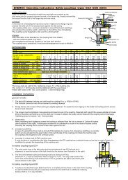
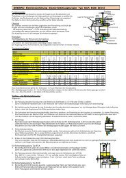
<strong>ENEMAC</strong> Operating instructions <strong>Safety</strong> couplings types ECA ECB (ECC)<br />
mode of function<br />
When the machine is operating normally the steel balls are pressed by the<br />
disk spring into the cupped recesses located in the flange ring, thereby transmitting<br />
the torque from the hub to the flange ring and vice-versa.<br />
overload<br />
In the event of overloading the hub turns round in relation to the flange ring and<br />
presses the balls out of the recesses back against the disk spring<br />
- the coupling clicks over - (once per revolution in case of fixed point switching)<br />
and actuates the proximity switch, which has to shut off the drive immediately.<br />
The coupling is only designed to click over for a short period !<br />
engage<br />
After elimination of the disturbance, the coupling has to be rotated<br />
- with low rotational speed or by hand -<br />
and reengages automatically (audible) in the fixed point position.<br />
The coupling now is operational, the adjusted disengagement torque is effective.<br />
technical data<br />
bearing for belt pulley<br />
hub<br />
flange ring<br />
ECA 1 3 6 16 25 40 63 75 100 130 250 400<br />
ECB + ECC 3 6 16 25 40 63 100 250 400<br />
torque range (adjustable)<br />
TA max (Nm)<br />
TA min (Nm)<br />
0,9<br />
0,5<br />
3<br />
1,2<br />
6<br />
2,5<br />
16<br />
6<br />
max. rotational speed (min –1 ) 3000 3000 3000 3000 3000 3000 2500 2500 2500 2500 2000 2000<br />
thread of screws h 2 6x M3 M4 M4 M4 M5 M5 M6 M6 M6 M6 M8 M8<br />
torque of hub screws h 2 (Nm) 1 1,5 1,5 2,5 3 4 6 6 8 8 35 35<br />
thread of flange ring h 1 6x M3 M4 M4 M4 M6 M6 M6 M6 M6 M6 M8 M8<br />
max. screw position i (mm) 6 8 8 10 12 12 12 12 12 12 16 16<br />
metal bellows data type ECC (type ECC is no longer available)<br />
max. shaft misalignment<br />
lateral (mm)<br />
axial ± (mm)<br />
0,27<br />
0,8<br />
0,27<br />
0,8<br />
0,2<br />
0,8<br />
torsion resistance (10 3 Nm/Rad) 5 5 21 33 33 54 66 108 164<br />
lateral spring rate (N/mm) 29 29 189 262 262 218 401 503 692<br />
25<br />
10<br />
0,2<br />
0,9<br />
The torque data are valid for the tightening screws h 2 of the bushing only.<br />
The screws h 1 for the pulley must be tightened with the usual torque !<br />
Please take notice of the max. screw position i (into the flange ring)<br />
installation instructions<br />
general remarks<br />
1. The kind of fit between bushing and shaft must be a sliding fit (e. g. H7/j6 or G7/k6).<br />
The frictional connection will not be impaired by existing keyways.<br />
45<br />
20<br />
0,2<br />
0,9<br />
75<br />
30<br />
0,2<br />
1,3<br />
75<br />
30<br />
130<br />
50<br />
0,2<br />
1,2<br />
h 1<br />
130<br />
50<br />
ECA<br />
ECB<br />
250<br />
100<br />
0,2<br />
1,2<br />
400<br />
160<br />
0,2<br />
1,0<br />
switching distance<br />
proximity<br />
switch<br />
steel balls<br />
bushing<br />
h 2<br />
adjustment nut<br />
disk spring<br />
switch plate<br />
2. During delivery the screws of the bushing are slightly tightened. To enable the hub slipping on the shaft, the bushing and it’s screws<br />
have to been loosened.<br />
3. The screws must be tightened cross-wise to avoid axial run-out of the coupling. Especially with type ECB a severe wobble will cause<br />
tilting of the pulley and seizing up on the shaft end. In case of collision the pulley cannot rotate and the coupling cannot disengage.<br />
Tightening torque of screws see Technical data.<br />
4. dismounting<br />
After unscrewing the 6 tightening screws the bushing is released from the hub by means of 3 draw-off screws<br />
(see illustration to the right). If axial space is restrictive it is advisable to screw in the draw-off screws before<br />
mounting the coupling and to counter check them against the hub.<br />
5. emergency switching<br />
In case of overload the drive must be turned off immediately by means of an emergency switching. A proximity<br />
switch can be activated by the axial motion of the switch plate of the coupling and initiate the machine stop.<br />
All couplings are designed for 250 overload cycles.<br />
6. mounting in vertical axes of CNC machine tools<br />
It must be taken in consideration that after disengagement the EC-coupling has a residuel torque so low that in most of cases it is<br />
insufficient to prevent the descenting of the machine axle.<br />
for safety couplings type ECA<br />
7. The axial center lines of the belt pulley and the ball bearing of type ECA should be in<br />
alignment, to prop the traction of the belt directly by the bearing (see illustration to the right).<br />
8. The kind of fit between pulley and bearing must be a sliding fit (H7/h5).<br />
Dimension k 2 must be machined within 0 trough +0.1 mm. The stop collar at left of the<br />
outer race of the bearing must at least have 3 mm to guarantee the plane rest of both parts<br />
(see illustration to the right).<br />
for safety couplings type ECB<br />
9. A pulley to be attached to type ECB must have a complete plane surface on the side of the coupling.<br />
As well the ECB as the pulley are separately centered to the shaft thus an additional centering<br />
between both is in no way tolerable.
<strong>ENEMAC</strong> Operating instructions <strong>Safety</strong> couplings types ECA ECB (ECC)<br />
for safety couplings type ECC (type ECC is no longer available)<br />
10. ATTENTION! The metal bellows of the ECC’s are made of thin stainless steel thus beeing susceptible to shocks.<br />
Damage to bellows can result in an unserviceable coupling !<br />
11. The ECC can compensate for shaft misalignments within certain limits<br />
(= max. lateral shaft misalignment see Technical data).<br />
It must be acted upon the following instructions to obtain the actual lateral shaft misalignment:<br />
The set-up of the dial gauge is shown by the picture, i. e. fastening of the gauge to one side<br />
(shaft 2) of the already mounted coupling and zero adjustment of the caliper.<br />
A 360° turn of the complete measuring system and observation of the maximum reading.<br />
The lateral shaft misalignment is half of this reading.<br />
In case of a set-up without a mounted ECC the dial gauge has to fastened to shaft 2 and the caliper adjusted to shaft 1. Turning shaft 2<br />
by 360° the maximum reading will include the amount of defect of form (=out of round), but this deviation can be neglected in nearly all<br />
cases.<br />
The complete 360° turn of the measuring system is essential !<br />
12. Mounting of the ECC-coupling<br />
The first step is to position the coupling loose on both shaft ends and then to tighten it to shaft 2. Possible axial tension of the bellows<br />
must be released by turning one shaft end while stopping the other one. The bushing of shaft 1 may not be tightened before completing<br />
this tension release. During mounting the bellows shall not be deformed too much. Permitted are 0.6 mm lateral and ± 1 mm axial.<br />
Under operation conditions however the values of Technical data are valid.<br />
adjustment of disengagement torque TA<br />
The disengement torque TA is continuously adjustable (without change the disk spring) !<br />
Special torque ranges on request.<br />
The couplings are pre-set by the manufacturer on assembly at about 70%<br />
of the maximum torque.<br />
The torque can be subsequently adjusted by turning the adjustment nut with a<br />
sickle spanner. Loosen the Allen set screws beforehand !<br />
IMPORTANT ! The characteristic curve of the disk spring is diminishing<br />
within the setting range !<br />
Opposite to the common practice this results in the effect,<br />
that turning the adjustment nut<br />
clockwise ⇒ TA decreases<br />
counter-clockwise ⇒ TA increases<br />
(see illustration to the right and foot)<br />
The really effective TA can only be measured precise, if<br />
♦ coupling and belt-pulley or intermediate flange are assembled or<br />
♦ the measuring device simulates this assembly and<br />
♦ points 7 trough 9 of the Installation instructions are taken into consideration<br />
range of adjustment<br />
adjustment nut<br />
conical hub<br />
Allen set screw<br />
marking<br />
torque TA<br />
characteristic curve<br />
of disk spring<br />
released<br />
shaft 1<br />
operating range<br />
setting range<br />
MAX<br />
ECC<br />
plan surface<br />
shaft 2<br />
switching<br />
distance<br />
MIN<br />
spring distance<br />
arrangement of disk spring<br />
The marking on the hub (see illustration to the left) must be between MIN and MAX in the<br />
adjustment range (=greater part of the circumference of the adjustment nut).<br />
By no means adjust torque below MIN, because in that case the disk spring will be blocked<br />
during disengagement, and the coupling will not operate.<br />
After adjustment the nut has to be fixed against turning by means of the Allen set srews<br />
(fixed with LOCTITE 222 or similar).<br />
<strong>ENEMAC</strong> <strong>GmbH</strong> Daimler Ring 42<br />
63839 Kleinwallstadt Germany<br />
� +49 (0) 6022 7107-0 � +49 (0) 6022 22237<br />
info@enemac.de enemac.de KW 10/12
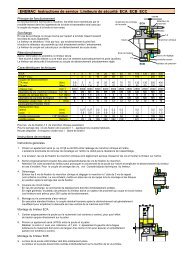
<strong>ENEMAC</strong> Operating instructions <strong>Torque</strong> <strong>Limiters</strong> types ECE ECG ECH ECI ECR<br />
mode of function<br />
When the machine is operating normally the steel balls are pressed by the<br />
disk spring into the cupped recesses located in the flange ring, thereby transmitting<br />
the torque from the hub to the flange ring and vice-versa.<br />
overload<br />
In the event of overloading the hub turns round in relation to the flange ring and<br />
presses the balls out of the recesses back against the disk spring<br />
- the clutch clicks over - (once per revolution in case of fixed point switching)<br />
and actuates the proximity switch, which has to shut off the drive immediately.<br />
The clutch is only designed to click over for a short period !<br />
engage<br />
After elimination of the disturbance, the clutch has to be rotated<br />
- with low rotational speed or by hand -<br />
and reengages automatically (audible) in the fixed point position.<br />
The clutch now is operational, the adjusted disengagement torque is effective.<br />
flange ring<br />
h<br />
hub<br />
h<br />
seat for<br />
sliding<br />
bearing<br />
ECR<br />
ECE<br />
ECG/ECI<br />
switching distance<br />
proximity<br />
switch<br />
threaded pin as<br />
axial fixation<br />
in „L“ version<br />
adjustment nut<br />
disk spring<br />
steel balls<br />
technical data<br />
ECE ECG 5 10 16 25 40 63 100 200 315 630 900<br />
ECI 5 10 16 25 40 63 100 200 315 630 900<br />
torque range (adjustable)<br />
TA max (Nm)<br />
TA min (Nm)<br />
5<br />
2<br />
10<br />
4<br />
16<br />
7<br />
25<br />
10<br />
max. rotational speed (min -1 ) 3000 3000 3000 3000 3000 3000 2500 2500 1800 1800 1800 1800 1800<br />
thread of flange ring h 6x M5 M5 M6 M6 M6 M6 M6 M6 M8 M10 M8 M10 M10<br />
max. screw position i (mm) 6 6 8 8 8 8 12 12 15 15 15 15 15<br />
ECR (stainless steel) 50 100 160 240<br />
torque range (adjustable)<br />
TA max (Nm)<br />
TA min (Nm)<br />
50<br />
15<br />
100<br />
40<br />
160<br />
60<br />
240<br />
100<br />
max. rotational speed (min -1 ) 3000 3000 2500 2500<br />
thread of flange ring h 6x M6 M6 M8 M8<br />
max. screw position i (mm) 8 8 12 12<br />
The screws h for the drive element must be tightened with the usual torque !<br />
Please take notice of the max. screw position i (into the flange ring).<br />
ECH (chain wheel integrated) 5 16 25 40 63 80 140 200 400 630 900<br />
torque range (adjustable)<br />
TA max (Nm)<br />
TA min (Nm)<br />
5<br />
2<br />
16<br />
6<br />
25<br />
10<br />
max. rotational speed (min -1 ) 3000 3000 3000 2800 2800 2500 2500 2000 2000 1500 1500<br />
installation instructions<br />
general remarks<br />
1. The fit between the hub and shaft should be chosen as close sliding fit (e. g. H7/j6 or G7/k6).<br />
Keyway according to DIN 6885 sheet 1.<br />
2. For axial fixation (against displacement on the shaft) threaded pins are provided that clamp the hubs against the keyways.<br />
An exception is the version „K“ in the types ECE/ECG and ECI, which are for example fixed by a stop collar and washer.<br />
3. The maximum rotational speeds specified in the Technical data refer only to the respective clutch by itself.<br />
If drive elements are incorporated that permit lower rotational speeds, these are obviously decisive,<br />
(e. g. the maximum permissible chain speed).<br />
40<br />
16<br />
4. Emergency switching<br />
In order to protect the machine and clutch, the drive must be shut off in the event of overloading !<br />
Normally the disk spring of the clutch activates, via the switching distance, a proximity switch arranged in axial direction and which<br />
disconnects the motor power circuit.<br />
for types ECE, ECG, ECI and ECR:<br />
5. The drive element (e. g. pulley) is simply bolted onto the clutch, the torque being transmitted by friction.<br />
6. ECE and pulley are both centred on the shaft and must not be additionally centred relative to one another by a fit bearing.<br />
7. With type ECE the drive element (e. g. pulley) must have its own sliding bearing on the shaft, which supports the tractive force<br />
of the belt. The clutch cannot absorb this force.<br />
8. Points 6 and 7 apply as appropriate to types ECG, ECI and ECR. In this case the drive element is centred and mounted directly on the<br />
clutch bearing instead of on the shaft. In order to have a lower sliding speed in the event of overloading, the sliding bearing is<br />
incorporated in the drive element (is therefore not included in the delivery specification of the ECG, ECI or ECR).<br />
9. The slide bearing clearance has to be < 0,03 mm.<br />
For the types ECG, ECI and ECR we recommend the installation of the slide bearing SKF type GLYCODUR F.<br />
The tolerance f 7 of the bearing is matched to these slide bearings.<br />
10. With type ECE an adapter flange enables also small pulleys or chain wheels to be installed.<br />
40<br />
16<br />
63<br />
25<br />
63<br />
25<br />
80<br />
32<br />
100<br />
40<br />
140<br />
56<br />
200<br />
80<br />
200<br />
80<br />
315<br />
140<br />
400<br />
160<br />
315<br />
140<br />
630<br />
280<br />
630<br />
280<br />
900<br />
400<br />
630<br />
280<br />
900<br />
400<br />
ECH
<strong>ENEMAC</strong> Operating instructions <strong>Torque</strong> <strong>Limiters</strong> types ECE ECG ECH ECI ECR<br />
adjustment of disengagement torque TA<br />
The disengagement torque TA is continuously adjustable (without change the disk spring) !<br />
Special torque ranges on request.<br />
The couplings are pre-set by the manufacturer on assembly at about 70%<br />
of the maximum torque.<br />
The torque can be subsequently adjusted by turning the adjustment nut with a<br />
sickle spanner. Loosen the Allen set screws beforehand !<br />
IMPORTANT ! The characteristic curve of the disk spring is diminishing<br />
within the setting range !<br />
range of adjustment<br />
Opposite to the common practice this results in the effect,<br />
that turning the adjustment nut ...<br />
clockwise ⇒ TA decreases<br />
counter-clockwise ⇒ TA increases<br />
(see illustration to the right and foot)<br />
adjustment nut<br />
hub<br />
Allen set screws<br />
marking<br />
torque TA<br />
characteristic curve<br />
of disk spring<br />
released<br />
operating range<br />
setting range<br />
MAX<br />
plan surface<br />
switching<br />
distance<br />
MIN<br />
spring distance<br />
arrangement of disk spring<br />
The marking on the hub (see illustration to the left) must be between MIN and MAX in the<br />
adjustment range (=greater part of the circumference of the adjustment nut).<br />
By no means adjust torque below MIN, because in that case the disk spring will be blocked<br />
during disengagement, and the coupling will not operate.<br />
After adjustment the nut has to be fixed against turning by means of the Allen set srews<br />
(fixed with LOCTITE 222 or similar).<br />
<strong>ENEMAC</strong> <strong>GmbH</strong> Daimler Ring 42<br />
63839 Kleinwallstadt Germany<br />
phone +49 (0) 6022 7107-0 fax +49 (0) 6022 22237<br />
info@enemac.de enemac.de KW 10/12
<strong>Torque</strong> <strong>Limiters</strong> type ECOL, ECP..., ECK..., ECU, ECAG<br />
Setting the disengagement torque TA<br />
The disengagement torque is generally between aprox. 40% and 100%<br />
of the nominal torque of the coupling and is stepless adjustable. If the<br />
customer does not specify a setting value, the setting is done at the<br />
maximum torque (nominal torque). The set static disengagement torque<br />
can be adjusted (on the machine) if necessary at a later date by turning the<br />
adjusting nut with a pin wrench. Adjusting nuts are provided with a user friendly<br />
scale; the disengagement torque, and the reference marks for TA min<br />
and TA max, are engraved on the face side of the adjusting nut to facilitate<br />
setting. Disengagement torques greater than TA max are possible (on<br />
request); a stronger wear of the disengagement mechanic is resulted.<br />
CAUTION ! Due to the degressive spring characteristic within the setting<br />
range, a turning back (counter-clockwise) of the adjusting nut means an<br />
increase, or a turning in clockwise direction means an reduction of the<br />
disengagement torque! (see direction arrow at clamping nut).<br />
setting marking by ECOL / ECP... / ECK... / ECU<br />
reference mark<br />
Release retaining screw. Turn adjusting nut with pin wrench (note reference mark). Tighten retaining screw after setting the required disengagement torque. Setting<br />
can be done by turning the adjusting nut with scale till the torque value to be set is in line with the reference mark. In mounted status the clamping screw must be<br />
released and after setting the disengagement torque it has to be fastened again.<br />
setting marking by ECAG<br />
adjusting nut<br />
reference mark on the hub setting range between Min - Max - mark<br />
thread for unfastening the cone ring<br />
retaining screw<br />
hole for pin wrench<br />
clamping screw<br />
retaining screw<br />
Unscrew retaining screw (see detail) completely; turn adjusting nut with pin wrench; after adjustment secure the adjustment nut against turning by drilling and tightening<br />
the self tapping screw.<br />
torque TA<br />
characteristic<br />
curve of<br />
disk spring<br />
Tel: + 49 (0) 6022 7107-0 Fax: + 49 (0) 6022 22237<br />
operating range<br />
setting range<br />
MAX<br />
released plan surface<br />
detail<br />
feed<br />
motion<br />
MIN<br />
spring distance<br />
arrangement of disk spring<br />
KW: 30/09