Viking Vcbb536rss Installation Instructions
Viking Vcbb536rss Installation Instructions
Viking Vcbb536rss Installation Instructions
Create successful ePaper yourself
Turn your PDF publications into a flip-book with our unique Google optimized e-Paper software.
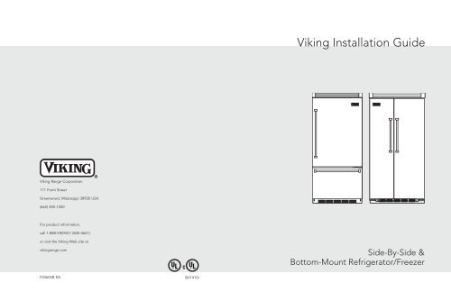
<strong>Viking</strong> <strong>Installation</strong> Guide<br />
<strong>Viking</strong> Range Corporation<br />
111 Front Street<br />
Greenwood, Mississippi 38930 USA<br />
(662) 455-1200<br />
For product information,<br />
call 1-888-VIKING1 (845-4641)<br />
or visit the <strong>Viking</strong> Web site at<br />
vikingrange.com<br />
U L<br />
C<br />
U L<br />
Side-By-Side &<br />
Bottom-Mount Refrigerator/Freezer<br />
F20605B EN (061410)
Table of Contents<br />
IMPORTANT–Please Read and Follow!<br />
Warnings & Important Information_____________________________________________________ 3<br />
Professional & Professional Integrated Side-by-Side<br />
Dimensions & Specifications (Professional 42” & 48”) ________________________________ 6<br />
Dimensions & Specifications (Professional Integrated 42” & 48”) _______________________8<br />
Cutout Dimensions (42”) _________________________________________________________10<br />
Anti-Tip Dimensions (42”) ________________________________________________________11<br />
Cutout Dimensions (48”)_________________________________________________________ 12<br />
Anti-Tip Dimensions (48”)________________________________________________________ 13<br />
Professional & Professional Integrated Bottom-Mount<br />
Dimensions & Specifications (36”)_________________________________________________ 14<br />
Cutout Dimensions (36”)_________________________________________________________ 16<br />
Anti-Tip Dimensions (36”)________________________________________________________ 17<br />
Cabinet Information (Professional) ____________________________________________________ 18<br />
Cabinet Information (Professional Integrated) __________________________________________ 20<br />
Designer Side-by-Side<br />
Dimensions & Specifications (42” & 48”)___________________________________________ 22<br />
Cutout Dimensions (42”)_________________________________________________________ 24<br />
Anti-Tip Dimensions (42”)________________________________________________________ 25<br />
Cutout Dimensions (48”)_________________________________________________________ 26<br />
Anti-Tip Dimensions (48”)________________________________________________________ 27<br />
Designer Bottom-Mount<br />
Dimensions & Specifications (36”)_________________________________________________ 28<br />
Cutout Dimensions (36”)_________________________________________________________ 30<br />
Anti-Tip Dimensions (36”)________________________________________________________ 31<br />
Cabinet Information (Designer)_______________________________________________________ 32<br />
Custom Side Panel Dimensions (Professional) __________________________________________ 34<br />
Custom Side Panel Dimensions (Designer & Professional Integrated) _____________________ 35<br />
General Information ________________________________________________________________ 36<br />
Unpacking & Moving _______________________________________________________________ 38<br />
<strong>Installation</strong>_________________________________________________________________________ 39<br />
Hinge Adjustment ______________________________________________________________ 40<br />
Kickplate <strong>Installation</strong> ____________________________________________________________ 42<br />
Door Stop Adjustment __________________________________________________________ 43<br />
Water Filter <strong>Installation</strong> __________________________________________________________ 44<br />
System Specifications and Data___________________________________________________ 45<br />
Final <strong>Installation</strong> ________________________________________________________________ 46<br />
Performance Checklist ______________________________________________________________ 47<br />
Control Panels _____________________________________________________________________ 48<br />
Service & Registration_______________________________________________________________ 49<br />
• Make sure that incoming voltage is the same<br />
as unit rating. An electric rating plate<br />
specifying voltage, frequency, wattage,<br />
amperage, and phase is attached to the<br />
product.<br />
• To reduce the risk of fire, electric shock, or<br />
injury to persons, installation work and<br />
electrical wiring must be done by qualified<br />
people in accordance with all applicable<br />
codes and standards, including fire-rated<br />
construction.<br />
• The installer should leave these instructions<br />
with the consumer who should retain them<br />
for local inspector’s use and for future<br />
reference.<br />
Your safety and the safety of others is<br />
very important.<br />
We have provided many important safety<br />
messages in this manual and on your<br />
appliance. Always read and obey all<br />
safety messages.<br />
This is the safety alert symbol. This<br />
symbol alerts you to hazards that<br />
can kill or hurt you and others.<br />
All safety messages will be preceded by the<br />
safety alert symbol and the word“DANGER”<br />
or “WARNING.” These words mean:<br />
D A N G E R<br />
You will be killed or seriously injured if<br />
you don’t follow instructions.<br />
W A R N I N G<br />
You can be killed or seriously injured if<br />
you don’t follow instructions.<br />
All safety messages will identify the<br />
hazard, tell you how to reduce the chance<br />
of injury, and tell you what can happen if<br />
the instructions are not followed.<br />
2<br />
3
IMPORTANT–Please Read and Follow!<br />
IMPORTANT–Please Read and Follow!<br />
A GFI shall be used if required by NFPA-70 (National Electric Code), federal/state/local<br />
laws, or local ordinances.<br />
• The required use of a GFI is normally related to the location of a receptacle with respect to<br />
any significant sources of water or moisture.<br />
• <strong>Viking</strong> Range Corporation will NOT warranty any problems resulting from GFI outlets which<br />
are not installed properly or do not meet the requirements below.<br />
If the use of a GFI is required, it should be:<br />
• Of the receptacle type (breaker type or portable type NOT recommended)<br />
• Used with permanent wiring only (temporary or portable wiring NOT recommended)<br />
• On a dedicated circuit (no other receptacles, switches or loads in the circuit)<br />
• Connected to a standard breaker of appropriate size (GFI breaker of the same size NOT<br />
recommended)<br />
• Rated for Class A (5 mA +/- 1 mA trip current) as per UL 943 standard)<br />
• In good condition and free from any loose-fitting gaskets (if applicable in outdoor situations)<br />
• Protected from moisture (water, steam, high humidity) as much as reasonably possible<br />
It is your responsibility to:<br />
• comply with installation specifications and dimensions.<br />
• properly install unit.<br />
• remove any moldings or decorative panels that prevent the unit from being serviced.<br />
• make sure that you have these materials (not provided with your unit), which are necessary<br />
for proper installation:<br />
• 1/4” (6 mm) copper tubing with shutoff valve<br />
• 6– #8 x 3” (7.6 cm) wood screws (longer screws may be required)<br />
• 1– Saddle valve (do not use self-piercing feature of the valve)<br />
• assure that floor will support unit, door panels and contents (approximately 1200 pounds [540 kg]).<br />
• provide a properly grounded electrical outlet.<br />
• assure that location will permit appliance doors to open 90° minimum.<br />
W A R N I N G<br />
ELECTRICAL SHOCK<br />
HAZARD<br />
Disconnect power or turn<br />
power disconnect switch to<br />
OFF position before removing<br />
top grille. Failure to do so can<br />
result in death or electrical shock.<br />
W A R N I N G<br />
TIP OVER HAZARD<br />
Appliance is top<br />
heavy and tips easily<br />
when not completely<br />
installed. Keep doors<br />
closed until appliance<br />
is completely installed<br />
and secured per installation instructions.<br />
Use two or more people to move and<br />
install appliance. Failure to do so can<br />
result in death or serious injury.<br />
Most of the unit’s weight is at the top. Extra care is needed when moving the unit to prevent<br />
tipping. Use cardboard shipping material or plywood under unit until it is installed in the<br />
operating position to protect floor surface.<br />
4<br />
5
Dimensions (Professional Side-By-Side)<br />
Specifications (Professional Side-By-Side)<br />
3–19/32”<br />
(9.1 cm)<br />
75–15/16”<br />
(192.9 cm)<br />
42” Professional<br />
42”<br />
(106.7 cm)<br />
41”<br />
(104.1 cm)<br />
1–1/2”<br />
(3.8 cm)<br />
9–5/32”<br />
(23.3 cm)<br />
82–3/4”<br />
3–19/32”<br />
(9.1 cm)<br />
48” Professional<br />
48”<br />
(121.9 cm)<br />
47”<br />
(119.4 cm)<br />
1–1/2”<br />
(3.8 cm)<br />
9–5/32”<br />
(23.3 cm)<br />
42” Professional Side-By-Side<br />
Description VCSB542 VCSB542D<br />
Overall width<br />
42” (106.7 cm)<br />
Overall height from bottom<br />
82-3/4” (210.2 cm) min. to 84-1/16” (213.5 cm) max.<br />
Overall depth from rear To front edge of side trim: 22-3/16” (56.4 cm)<br />
To front of top grille: 24-11/16” (62.7 cm)<br />
To front of handle endcap: 27-1/4” (69.2 cm)<br />
Cutout width<br />
41-1/2” (105.4 cm) min. to 41-3/4” (106 cm) max.<br />
Cutout height<br />
82-7/8” (210.5 cm) min. to 84-1/16” (213.5 cm) max.<br />
Cutout depth<br />
24” (61.0 cm) min.<br />
Electrical requirements<br />
115 volt, 60 Hz, 15 amp dedicated circuit; 3-wire cord with<br />
grounded 3-prong plug attached to product<br />
Maximum amp usage<br />
9.9 amps<br />
Inlet water 1/4” copper tubing inlet waterline; 1/4” copper tubing inlet waterline;<br />
Requirements minimum 20 psi; maximum 120 psi minimum 35 psi; maximum 120 psi<br />
Overall interior dimensions<br />
Refrigerator 15.0 cu. ft. (425 liters) 15.0 cu. ft. (425 liters)<br />
Freezer 9.0 cu. ft. (255 liters) 8.6 cu. ft. (243 liters)<br />
Total capacity 24.0 cu. ft. (680 liters) 23.6 cu. ft. (668 liters)<br />
Approximate shipping weight 652 lbs. (293.4 kg) 676 lbs. (304.2 kg)<br />
27–1/4”<br />
(69.2 cm)<br />
20–3/4”<br />
(52.7 cm)<br />
22–3/16”<br />
(56.4 cm)<br />
24–11/16”<br />
(62.7 cm)<br />
(210.2 cm)<br />
min.<br />
to<br />
84–1/16”<br />
(213.5 cm)<br />
max.<br />
75–15/16”<br />
(192.9 cm)<br />
27–1/4”<br />
(69.2 cm)<br />
20–3/4”<br />
(52.7 cm)<br />
22–3/16”<br />
(56.4 cm)<br />
24–11/16”<br />
(62.7 cm)<br />
82–3/4”<br />
(210.2 cm)<br />
min.<br />
to<br />
84–1/16”<br />
(213.5 cm)<br />
max.<br />
48” Professional Side-By-Side<br />
Description VCSB548 VCSB548D<br />
Overall width<br />
48” (121.9 cm)<br />
Overall height from bottom<br />
82-3/4” (210.2 cm) min. to 84-1/16” (213.5 cm) max.<br />
Overall depth from rear To front edge of side trim: 22-3/16” (56.4 cm)<br />
To front of top grille: 24-11/16” (62.7 cm)<br />
To front of handle endcap: 27-1/4” (69.2 cm)<br />
Cutout width<br />
47-1/2” (120.7 cm) min. to 47-3/4” (121.3 cm) max.<br />
Cutout height<br />
82-7/8” (210.5 cm) min. to 84-1/16” (213.5 cm) max.<br />
Cutout depth<br />
24” (61.0 cm) min.<br />
Electrical requirements<br />
115 volt, 60 Hz, 15 amp dedicated circuit; 3-wire cord with<br />
grounded 3-prong plug attached to product<br />
Maximum amp usage<br />
9.9 amps<br />
Inlet water 1/4” copper tubing inlet waterline; 1/4” copper tubing inlet waterline;<br />
Requirements minimum 20 psi; maximum 120 psi minimum 35 psi; maximum 120 psi<br />
Overall interior dimensions<br />
Refrigerator 18.5 cu. ft. (524 liters) 18.5 cu. ft. (524 liters)<br />
Freezer 8.9 cu. ft. (252 liters) 8.6 cu. ft. (243 liters)<br />
Total capacity 27.4 cu. ft. (776 liters) 27.1 cu. ft. (767 liters)<br />
Approximate shipping weight 715 lbs. (321.8 kg) 735 lbs. (330.8 kg)<br />
6<br />
7
Dimensions (Professional Side-By-Side)<br />
Specifications (Professional Side-By-Side)<br />
42” Professional Integrated Side-By-Side<br />
3–19/32”<br />
(9.1 cm)<br />
75–15/16”<br />
(192.9 cm)<br />
42” Professional Integrated<br />
42”<br />
(106.7 cm)<br />
41”<br />
(104.1 cm)<br />
1–1/2”<br />
(3.8 cm)<br />
9–5/32”<br />
(23.3 cm)<br />
82–3/4”<br />
3–19/32”<br />
(9.1 cm)<br />
48” Professional Integrated<br />
48”<br />
(121.9 cm)<br />
47”<br />
(119.4 cm)<br />
1–1/2”<br />
(3.8 cm)<br />
9–5/32”<br />
(23.3 cm)<br />
Description VISB542 VISB542D<br />
Overall width<br />
42” (106.7 cm)<br />
Overall height from bottom<br />
82-3/4” (210.2 cm) min. to 84-1/16” (213.5 cm) max.<br />
Overall depth from rear To front edge of side trim: 23-3/8” (59.4 cm)<br />
To front of top grille: 24” (61.0 cm)<br />
To front of handle endcap: 26-1/2” (67.3 cm)<br />
Cutout width<br />
42” (106.7 cm)<br />
Cutout height<br />
82-7/8” (210.5 cm) min. to 84-1/16” (213.5 cm) max.<br />
Cutout depth<br />
24” (61.0 cm) min.<br />
Electrical requirements<br />
115 volt, 60 Hz, 15 amp dedicated circuit; 3-wire cord with<br />
grounded 3-prong plug attached to product<br />
Maximum amp usage<br />
9.9 amps<br />
Inlet water 1/4” copper tubing inlet waterline; 1/4” copper tubing inlet waterline;<br />
requirements minimum 20 psi; maximum 120 psi minimum 35 psi; maximum 120 psi<br />
Overall interior dimensions<br />
Refrigerator 15.0 cu. ft. (425 liters) 15.0 cu. ft. (411 liters)<br />
Freezer 9.0 cu. ft. (255 liters) 8.6 cu. ft. (244 liters)<br />
Total capacity 24.0 cu. ft. (680 liters) 23.6 cu. ft. (668 liters)<br />
Approximate shipping weight 625 lbs. (293.4 kg) 676 lbs. (304.2 kg)<br />
26–1/2”<br />
(67.3 cm)<br />
20–3/4”<br />
(52.7 cm)<br />
23–3/8”<br />
(59.4 cm)<br />
24”<br />
(61.0 cm)<br />
(210.2 cm)<br />
min.<br />
to<br />
84–1/16”<br />
(213.5 cm)<br />
max.<br />
75–15/16”<br />
(192.9 cm)<br />
26–1/2”<br />
(67.3 cm)<br />
20–3/4”<br />
(52.7 cm)<br />
23–3/8”<br />
(59.4 cm)<br />
24”<br />
(61.0 cm)<br />
82–3/4”<br />
(210.2 cm)<br />
min.<br />
to<br />
84–1/16”<br />
(213.5 cm)<br />
max.<br />
48” Professional Integrated Side-By-Side<br />
Description VISB548 VISB548D<br />
Overall width<br />
48” (121.9 cm)<br />
Overall height from bottom<br />
82-3/4” (210.2 cm) min. to 84-1/16” (213.5 cm) max.<br />
Overall depth from rear To front edge of side trim: 23-3/8” (59.4 cm)<br />
To front of top grille: 24” (61.0 cm)<br />
To front of handle endcap: 26-1/2” (67.3 cm)<br />
Cutout width<br />
48” (121.9 cm)<br />
Cutout height<br />
82-7/8” (210.5 cm) min. to 84-1/16” (213.5 cm) max.<br />
Cutout depth<br />
24” (61.0 cm) min.<br />
Electrical requirements<br />
115 volt, 60 Hz, 15 amp dedicated circuit; 3-wire cord with<br />
grounded 3-prong plug attached to product<br />
Maximum amp usage<br />
9.9 amps<br />
Inlet water 1/4” copper tubing inlet waterline; 1/4” copper tubing inlet waterline;<br />
requirements minimum 20 psi; maximum 120 psi minimum 35 psi; maximum 120 psi<br />
Overall interior dimensions<br />
Refrigerator 18.5 cu. ft. (524 liters) 18.5 cu. ft. (507 liters)<br />
Freezer 8.9 cu. ft. (252 liters) 8.6 cu. ft. (243 liters)<br />
Total capacity 27.4 cu. ft. (776 liters) 27.1 cu. ft. (767 liters)<br />
Approximate shipping weight 715 lbs. (321.8 kg) 735 lbs. (330.8 kg)<br />
8<br />
9
(26.7 cm)<br />
Cutout Dimensions (Professional Side-By-Side)<br />
Anti-Tip Dimensions (Professional Side-By-Side)<br />
42” Professional & Professional Integrated 42” Professional<br />
24”<br />
(61.0 cm)<br />
Electric Outlet Location<br />
Professional Anti-Tip Location<br />
See Anti-Tip board installation<br />
9”<br />
(22.9 cm)<br />
6”<br />
(15.2 cm)<br />
9”<br />
(22.9 cm)<br />
3”<br />
(7.6 cm)<br />
Two 2”x 4” Mounting Boards<br />
3” (7.6 cm) x 3-1/2” (8.9 cm)<br />
35”<br />
(88.9 cm)<br />
82–7/8”<br />
(210.5 cm) min.<br />
79–3/8”<br />
3–1/2”<br />
(8.9 cm)<br />
anti-tip board &<br />
opening height<br />
(201.6 cm) min.<br />
to bottom of<br />
anti-tip board<br />
84–1/16”<br />
80–1/2”<br />
(213.5 cm) max.<br />
anti-tip board &<br />
opening height<br />
73-3/8”<br />
(186.4 cm)<br />
(204.6 cm) max.<br />
to bottom of<br />
anti-tip board<br />
NOTE: If unit is installed deeper than<br />
24” (61.0 cm),then shim behind the mounting<br />
board by the difference.<br />
Water Line Entry Area<br />
42”<br />
(106.7 cm)<br />
Professional Integrated Anti-Tip Location<br />
One 2”x 4” Mounting Board<br />
3” (7.6 cm) x 3-1/2” (8.9 cm)<br />
41–1/2”<br />
(105.4 cm) min.<br />
to<br />
41–3/4”<br />
(106.0 cm) max.<br />
42”<br />
(106.7 cm)<br />
Professional Integrated<br />
models only<br />
7–5/8”<br />
Professional Integrated<br />
models only<br />
41–1/2”<br />
3–5/8”<br />
(9.2 cm)<br />
5/8”<br />
(1.6 cm)<br />
10–3/4”<br />
(19.4 cm)<br />
3”<br />
(7.6 cm)<br />
6–3/4”<br />
(17.1 cm)<br />
10–1/2”<br />
(105.4 cm)<br />
5/8”<br />
(1.6 cm)<br />
1”<br />
(2.5 cm)<br />
3–1/2”<br />
(8.9 cm)<br />
1.5”<br />
(3.8 cm)<br />
35”<br />
(88.9 cm)<br />
(27.3 cm)<br />
5/8”<br />
(1.6 cm)<br />
Bottom of anti-tip board is 3–7/8” (9.8 cm) below opening height.<br />
NOTE: Top of unit must be placed firmly under anti-tip board.<br />
Optional floor<br />
water line entry<br />
NOTE: If unit is installed deeper than<br />
24” (61.0 cm), then shim behind the mounting<br />
board by the difference.<br />
10<br />
11
(26.7 cm)<br />
Cutout Dimensions (Professional Side-By-Side)<br />
Anti-Tip Dimensions (Professional Side-By-Side)<br />
24”<br />
(61.0 cm)<br />
48” Professional & Professional Integrated 48” Professional & Professional Integrated<br />
Electric Outlet Location<br />
Professional Anti-Tip Location<br />
See Anti-Tip board installation<br />
9”<br />
(22.9 cm)<br />
6”<br />
(15.2 cm)<br />
9”<br />
(22.9 cm)<br />
3”<br />
(7.6 cm)<br />
Two 2”x 4” Mounting Boards<br />
3” (7.6 cm) x 3-1/2” (8.9 cm)<br />
41”<br />
(104.1 cm)<br />
82–7/8”<br />
(210.5 cm) min.<br />
anti-tip board &<br />
opening height<br />
79–3/8”<br />
(201.6 cm) min.<br />
to bottom of<br />
anti-tip board<br />
3–1/2”<br />
(8.9 cm)<br />
84–1/16”<br />
(213.5 cm) max.<br />
80–1/2”<br />
(204.6 cm) max.<br />
anti-tip board &<br />
opening height<br />
73-3/8”<br />
(186.4 cm)<br />
to bottom of<br />
anti-tip board<br />
NOTE: If unit is installed deeper than<br />
24” (61.0 cm), then shim behind the mounting<br />
board by the difference.<br />
Water Line Entry Area<br />
48”<br />
(121.9 cm)<br />
Professional Integrated Anti-Tip Location<br />
One 2”x 4” Mounting Board<br />
3” (7.6 cm) x 3-1/2” (8.9 cm)<br />
47–1/2”<br />
(120.7 cm) min.<br />
to<br />
47–3/4”<br />
(121.2 cm) max.<br />
48”<br />
(121.9 cm)<br />
Professional Integrated<br />
models only<br />
7–5/8”<br />
Professional Integrated<br />
models only<br />
47–1/2”<br />
3–5/8”<br />
(9.2 cm)<br />
5/8”<br />
(1.6 cm)<br />
10–3/4”<br />
(19.4 cm)<br />
3”<br />
(7.6 cm)<br />
6–3/4”<br />
(17.1 cm)<br />
10–1/2”<br />
(120.7 cm)<br />
5/8”<br />
(1.6 cm)<br />
1”<br />
(2.5 cm)<br />
3–1/2”<br />
(8.9 cm)<br />
1-1/2”<br />
(3.8 cm)<br />
41”<br />
(104.1 cm)<br />
(27.3 cm)<br />
5/8”<br />
(1.6 cm)<br />
Bottom of anti-tip board is 3–7/8” (9.8 cm) below opening height.<br />
NOTE: Top of unit must be placed firmly under anti-tip board.<br />
Optional floor<br />
water line entry<br />
NOTE: If unit is installed deeper than<br />
24” (61.0 cm), then shim behind the mounting<br />
board by the difference.<br />
12<br />
13
Dimensions (Professional Bottom-Mount)<br />
Specifications (Professional Bottom-Mount)<br />
3–19/32”<br />
(9.1 cm)<br />
52”<br />
(132.1 cm)<br />
23–1/16”<br />
(58.5 cm)<br />
36” Professional<br />
27–1/4”<br />
(69.2 cm)<br />
36”<br />
(91.5 cm)<br />
35”<br />
(88.9 cm)<br />
20–3/4”<br />
(52.7 cm)<br />
22–3/16”<br />
(56.4 cm)<br />
24–11/16”<br />
(62.7 cm)<br />
1–1/2”<br />
(3.8 cm)<br />
9–5/32”<br />
(23.3 cm)<br />
82–3/4”<br />
(210.2 cm)<br />
min.<br />
to<br />
84–1/16”<br />
(213.5 cm)<br />
max.<br />
3–19/32”<br />
(9.1 cm)<br />
52”<br />
(132.1 cm)<br />
23–1/16”<br />
(58.5 cm)<br />
36” Professional Integrated<br />
26–1/2”<br />
(67.3 cm)<br />
36”<br />
(91.5 cm)<br />
35”<br />
(88.9 cm)<br />
20–3/4”<br />
(52.7 cm)<br />
23–3/8”<br />
(59.4 cm)<br />
24”<br />
(61.0 cm)<br />
1–1/2”<br />
(3.8 cm)<br />
9–5/32”<br />
(23.3 cm)<br />
82–3/4”<br />
(210.2 cm)<br />
min.<br />
to<br />
84–1/16”<br />
(213.5 cm)<br />
max.<br />
36” Professional Bottom-Mount<br />
Description<br />
VCBB536<br />
Overall width<br />
36” (91.5 cm)<br />
Overall height from bottom<br />
82-3/4” (210.2 cm) min. to 84-1/16” (213.5 cm) max.<br />
Overall depth from rear To front edge of side trim: 22-3/16” (56.4 cm)<br />
To front of top grille: 24-11/16” (62.7 cm)<br />
To front of handle endcap: 27-1/4” (69.2 cm)<br />
Cutout wdth<br />
35-1/2” (90.2 cm) min. to 35-3/4” (90.8 cm) max.<br />
Cutout height<br />
82-7/8” (210.5 cm) min. to 84-1/16” (213.5 cm) max.<br />
Cutout depth<br />
24” (61.0 cm) min.<br />
Electrical requirements<br />
115 volt, 60 Hz, 15 amp dedicated circuit; 3-wire cord with<br />
grounded 3-prong plug attached to product<br />
Maximum amp usage<br />
9.9 amps<br />
Inlet water<br />
1/4” copper tubing inlet waterline; minimum 20 psi;<br />
requirements<br />
maximum 120 psi<br />
Overall interior dimensions<br />
Refrigerator<br />
15.2 cu. ft. (431 Liters)<br />
Freezer<br />
5.1 cu. ft. (145 Liters)<br />
Total capacity<br />
20.3 cu. ft. (576 Liters)<br />
Approximate shipping weight<br />
565 lbs. (254.3 kg)<br />
36” Professional Integrated Bottom-Mount<br />
Description<br />
VIBB536<br />
Overall width<br />
36” (91.5 cm)<br />
Overall height from bottom<br />
82-3/4” (210.2 cm) min. to 84-1/16” (213.5 cm) max.<br />
Overall depth from rear To front edge of side trim: 23-3/8” (59.4 cm)<br />
To front of top grille: 24” (61.0 cm)<br />
To front of handle endcap: 26-1/2” (67.3 cm)<br />
Cutout wdth<br />
36” (91.4 cm)<br />
Cutout height<br />
82-7/8” (210.5 cm) min. to 84-1/16” (213.5 cm) max.<br />
Cutout depth<br />
24” (61.0 cm) min.<br />
Electrical requirements<br />
115 volt, 60 Hz, 15 amp dedicated circuit; 3-wire cord with<br />
grounded 3-prong plug attached to product<br />
Maximum amp usage<br />
9.9 amps<br />
Inlet water<br />
1/4” copper tubing inlet waterline; minimum 20 psi;<br />
requirements<br />
maximum 120 psi<br />
Overall interior dimensions<br />
Refrigerator<br />
15.2 cu. ft. (431 Liters)<br />
Freezer<br />
5.1 cu. ft. (145 Liters)<br />
Total capacity<br />
20.3 cu. ft. (576 Liters)<br />
Approximate shipping weight<br />
565 lbs. (254.3 kg)<br />
14<br />
15
Cutout Dimensions (Professional Bottom-Mount)<br />
Anti-Tip Dimensions (Professional Bottom-Mount)<br />
36” Professional & Professional Integrated 36” Professional & Professional Integrated<br />
24”<br />
(61.0 cm)<br />
Electric Outlet Location<br />
Professional Anti-Tip Location<br />
See Anti-Tip board installation<br />
9”<br />
(22.9 cm)<br />
6”<br />
(15.2 cm)<br />
9”<br />
(22.9 cm)<br />
79–3/8”<br />
(201.6 cm) min.<br />
to bottom of<br />
anti-tip board<br />
3”<br />
(7.6 cm)<br />
Two 2”x 4” Mounting Boards<br />
3” (7.6 cm) x 3-1/2” (8.9 cm)<br />
29–1/2”<br />
(74.9 cm)<br />
82–7/8”<br />
(210.5 cm) min.<br />
anti-tip board &<br />
opening height<br />
80–1/2”<br />
(204.6 cm) max.<br />
3–1/2”<br />
(8.9 cm)<br />
to bottom of<br />
anti-tip board<br />
84–1/16”<br />
(213.5 cm) max.<br />
anti-tip board &<br />
opening height<br />
73-3/8”<br />
(186.4 cm)<br />
NOTE: If unit is installed deeper than<br />
24” (61.0 cm), then shim behind the mounting<br />
boards by the difference.<br />
Water Line Entry Area<br />
36”<br />
(91.5 cm)<br />
Professional Integrated Anti-Tip Location<br />
Professional Integrated<br />
model only<br />
35–1/2”<br />
One 2”x 4” Mounting Board<br />
3” (7.6 cm) x 3-1/2” (8.9 cm)<br />
7–5/8”<br />
(90.2 cm)<br />
35–1/2”<br />
5/8”<br />
(1.6 cm)<br />
(19.4 cm)<br />
3”<br />
(7.6 cm)<br />
6–3/4”<br />
(17.1 cm)<br />
1.5”<br />
(3.8 cm)<br />
29–1/2”<br />
(74.9 cm)<br />
(90.2 cm) min.<br />
to<br />
35–3/4”<br />
(90.8 cm) max.<br />
36”<br />
(91.5 cm)<br />
Professional Integrated<br />
model only<br />
3–5/8”<br />
(9.2 cm)<br />
10–3/4”<br />
10–1/2”<br />
5/8”<br />
(1.6 cm)<br />
1”<br />
(2.5 cm)<br />
3–1/2”<br />
(8.9 cm)<br />
(27.3 cm)<br />
(26.7 cm)<br />
5/8”<br />
(1.6 cm)<br />
Bottom of anti-tip board is 3–7/8” (9.8 cm) below opening height.<br />
NOTE: Top of unit must be placed firmly under anti-tip board.<br />
Optional floor<br />
water line entry<br />
NOTE: If unit is installed deeper than<br />
24” (61.0 cm), then shim behind the mounting<br />
boards by the difference.<br />
16<br />
17
Cabinet Information (Professional)<br />
Cabinet Information (Professional)<br />
Professional models fit “semi-flush” in standard 24” (61.0 cm) deep cabinet openings. The door<br />
face protrudes 2-1/2” (6.4 cm) from the cabinet face. The handle protrudes an additional<br />
2-1/2” (6.4 cm) into the room.<br />
Top View<br />
Wall<br />
Professional models fit “semi-flush” in standard 24” (61.0 cm) deep cabinet openings. The door<br />
face protrudes 2-1/2” (6.4 cm) from the cabinet face. The handles protrude an additional<br />
2-1/2” (6.4 cm) into the room.<br />
Top View<br />
Top View<br />
Wall<br />
1–13/16”<br />
(4.6 cm)<br />
Space if 24”<br />
standard<br />
cabinet<br />
depth is<br />
used<br />
Door<br />
3/4”<br />
(1.9 cm)<br />
Full End<br />
Panel<br />
2–1/2”<br />
(6.4 cm) Offset<br />
24”<br />
(61.0 cm)<br />
Standard<br />
Cabinet<br />
Depth<br />
Partial Overlay<br />
Cabinet Door<br />
1–13/16”<br />
(4.6 cm)<br />
Space if 24”<br />
standard<br />
cabinet<br />
depth is<br />
used<br />
Door<br />
3/4”<br />
(1.9 cm)<br />
Full End<br />
Panel<br />
Wall<br />
2–1/2”<br />
(6.4 cm) Offset<br />
24”<br />
(61.0 cm)<br />
Standard<br />
Cabinet<br />
Depth<br />
Countertop<br />
Overhang<br />
24”<br />
(61.0 cm)<br />
Standard<br />
Cabinet<br />
Depth<br />
1–13/16”<br />
(4.6 cm)<br />
Space if 24”<br />
standard<br />
cabinet<br />
depth is<br />
used<br />
3/4”<br />
(1.9 cm)<br />
Full End<br />
Panel<br />
5/16”<br />
(0.8 cm)<br />
Door<br />
2–1/2”<br />
(6.4 cm) Offset<br />
18<br />
19
Cabinet Information (Professional Integrated)<br />
Professional Integrated models fit flush in standard 24” (61.0 cm) deep cabinet openings with no<br />
protrusion into the room except the handle protrudes 2-1/2” (6.4 cm) into the room.<br />
Top View<br />
Overlapping cabinet doors<br />
3/4”<br />
(1.9 cm)<br />
space if<br />
24” (61.0 cm)<br />
standard<br />
cabinet depth<br />
is used<br />
3/4”<br />
(1.9 cm)<br />
Full End<br />
Panel<br />
Wall<br />
24”<br />
(61.0 cm)<br />
Standard<br />
Cabinet<br />
Depth<br />
24-3/4”<br />
(62.9 cm)<br />
Cabinet Information (Professional Integrated)<br />
Professional Integrated models fit flush in standard 24” (61.0 cm) deep cabinet openings with no<br />
protrusion into the room except the handle protrudes 2-1/2” (6.4 cm) into the room.<br />
1”<br />
(2.5 cm)<br />
space if<br />
25” (63.5 cm)<br />
cabinet depth<br />
is used<br />
Top View<br />
Wall<br />
3/4”<br />
(1.9 cm)<br />
Full End<br />
Panel<br />
25”<br />
(63.5 cm)<br />
Countertop<br />
Depth<br />
24”<br />
(61.0 cm)<br />
Standard<br />
Cabinet<br />
Depth<br />
Door<br />
Flush<br />
Cabinet<br />
Door<br />
Door<br />
Top View<br />
Flush mount cabinet doors<br />
Top View<br />
Wall<br />
Flush<br />
1”<br />
(2.5 cm)<br />
space if<br />
25” (63.5 cm)<br />
cabinet depth<br />
is used<br />
3/4”<br />
(1.9 cm)<br />
Full End<br />
Panel<br />
Wall<br />
25”<br />
(63.5 cm)<br />
Cabinet<br />
Depth<br />
25”<br />
(63.5 cm)<br />
1”<br />
(2.5 cm)<br />
space if<br />
25” (63.5 cm)<br />
cabinet depth<br />
is used<br />
3/4”<br />
(1.9 cm)<br />
Full End<br />
Panel<br />
Door<br />
Cabinet<br />
Door<br />
Flush<br />
Door<br />
Flush<br />
20<br />
21
Dimensions (Designer Side-By-Side)<br />
Specifications (Designer Side-By-Side)<br />
42” Designer Side-By-Side<br />
3–1/2”<br />
(8.9 cm)<br />
75–15/16”<br />
(192.9 cm)<br />
Designer 42”<br />
42”<br />
(106.7 cm)<br />
41”<br />
(104.1 cm)<br />
1–1/2”<br />
(3.8 cm)<br />
9–5/32”<br />
(23.3 cm)<br />
82–3/4”<br />
(210.2 cm)<br />
min.<br />
to<br />
3–1/2”<br />
(8.9 cm)<br />
Designer 48”<br />
48”<br />
(121.9 cm)<br />
47”<br />
(119.4 cm)<br />
1–1/2”<br />
(3.8 cm)<br />
9–5/32”<br />
(23.3 cm)<br />
Description DDSB542 DDSB542D<br />
Overall width<br />
42” (106.7 cm)<br />
Overall height from bottom<br />
82-3/4” (210.2 cm) min. to 84-1/16” (213.5 cm) max.<br />
Overall depth from rear To front edge of side trim: 23-3/8” (59.4 cm)<br />
To front of top gr:ille: 24” (61.0 cm)<br />
To front of handle:<br />
26-1/2” (67.3 cm)<br />
Cutout width<br />
42” (106.7 cm)<br />
Cutout height<br />
82-7/8” (210.5 cm) min. to 84-1/16” (213.5 cm) max.<br />
Cutout depth<br />
24” (61.0 cm) min.<br />
Electrical requirements<br />
115 volt, 60 Hz, 15 amp dedicated circuit; 3-wire cord with<br />
grounded 3-prong plug attached to product<br />
Maximum amp usage<br />
9.9 amps<br />
Inlet water 1/4” copper tubing inlet waterline; 1/4” copper tubing inlet waterline;<br />
Requirements minimum 20 psi; maximum 120 psi minimum 35 psi; maximum 120 psi<br />
Overall interior dimensions<br />
Refrigerator 15.0 cu. ft. (425 liters) 15.0 cu. ft. (425 liters)<br />
Freezer 9.0 cu. ft. (255 liters) 8.6 cu. ft. (243 liters)<br />
Total capacity 24.0 cu. ft. (680 liters) 23.6 cu. ft. (668 liters)<br />
Approximate shipping weight 642 lbs. (289 kg) 665 lbs. (299.3 kg)<br />
26-1/2”<br />
(67.3 cm)<br />
20–3/4”<br />
(52.7 cm)<br />
23–3/8”<br />
(59.4 cm)<br />
24”<br />
(61.0 cm)<br />
84–1/16”<br />
(213.5 cm)<br />
max.<br />
75–15/16”<br />
(192.9 cm)<br />
26-1/2”<br />
(67.3 cm)<br />
20–3/4”<br />
(52.7 cm)<br />
23–3/8”<br />
(59.4 cm)<br />
24”<br />
(61.0 cm)<br />
82–3/4”<br />
(210.2 cm)<br />
min.<br />
to<br />
84–1/16”<br />
(213.5 cm)<br />
max.<br />
48” Designer Side-By-Side<br />
Description DDSB548 DDSB548D<br />
Overall width<br />
48” (121.9 cm)<br />
Overall height from bottom<br />
82-3/4” (210.2 cm) min. to 84-1/16” (213.5 cm) max.<br />
Overall depth from rear To front edge of side trim: 23-3/8” (59.4 cm)<br />
To front of top grille: 24” (61.0 cm)<br />
To front of handle:<br />
26-1/2” (67.3 cm)<br />
Cutout width<br />
48” (121.9 cm)<br />
Cutout height<br />
82-7/8” (210.5 cm) min. to 84-1/16” (213.5 cm) max.<br />
Cutout depth<br />
24” (61.0 cm) min.<br />
Electrical requirements<br />
115 volt, 60 Hz, 15 amp dedicated circuit; 3-wire cord with<br />
grounded 3-prong plug attached to product<br />
Maximum amp usage<br />
9.9 amps<br />
Inlet water 1/4” copper tubing inlet waterline; 1/4” copper tubing inlet waterline;<br />
Requirements minimum 20 psi; maximum 120 psi minimum 35 psi; maximum 120 psi<br />
Overall interior dimensions<br />
Refrigerator 18.5 cu. ft. (524 liters) 18.5 cu. ft. (524 liters)<br />
Freezer 8.9 cu. ft. (252 liters) 8.6 cu. ft. (243 liters)<br />
Total capacity 27.4 cu. ft. (776 liters) 27.1 cu. ft. (767 liters)<br />
Approximate shipping weight 705 lbs. (317.3 kg) 730 lbs. (328.5 kg)<br />
22<br />
23
(26.7 cm)<br />
Cutout Dimensions (Designer Side-By-Side)<br />
Anti-Tip Dimensions (Designer Side-By-Side)<br />
24”<br />
(61.0 cm)<br />
See Anti-Tip board installation<br />
42” Designer 42” Designer<br />
Electric Outlet Location<br />
9”<br />
(22.9 cm)<br />
6”<br />
(15.2 cm)<br />
9”<br />
(22.9 cm)<br />
Anti-Tip Location<br />
82–7/8”<br />
(210.5 cm) min.<br />
anti-tip board &<br />
opening height<br />
79–3/8”<br />
(201.6 cm) min.<br />
to bottom of<br />
anti-tip board<br />
1–1/2”<br />
(3.8 cm)<br />
35”<br />
(88.9 cm)<br />
84–1/16”<br />
(213.5 cm) max.<br />
anti-tip board &<br />
opening height<br />
(204.6 cm) max.<br />
to bottom of<br />
anti-tip board<br />
3–1/2”<br />
(8.9 cm)<br />
80–1/2”<br />
73–3/8”<br />
(186.4 cm)<br />
Water Line Entry Area<br />
42”<br />
(106.7 cm)<br />
42”<br />
(106.7 cm)<br />
5/8”<br />
(1.6 cm)<br />
7–5/8”<br />
(19.4 cm)<br />
3”<br />
(7.6 cm)<br />
6–3/4”<br />
(17.1 cm)<br />
One 2”x 4” Mounting Board<br />
1–1/2” (3.8 cm) x 3–1/2” (8.9 cm)<br />
NOTE: If unit is installed deeper than 24” (61.0 cm), then shim<br />
behind the mounting board by the difference.<br />
3–5/8”<br />
(9.2 cm)<br />
10–3/4”<br />
10–1/2”<br />
5/8”<br />
(1.6 cm)<br />
1”<br />
(2.5 cm)<br />
Bottom of anti-tip board is 3–7/8” (9.8 cm) below opening height.<br />
NOTE: Top of unit must be placed firmly under anti-tip board.<br />
(27.3 cm)<br />
5/8”<br />
(1.6 cm)<br />
Optional floor<br />
water line entry<br />
24<br />
25
Cutout Dimensions (Designer Side-By-Side)<br />
Anti-Tip Dimensions (Designer Side-By-Side)<br />
24”<br />
(61.0 cm)<br />
See Anti-Tip board installation<br />
48” Designer 48” Designer<br />
Electric Outlet Location<br />
9”<br />
(22.9 cm)<br />
6”<br />
(15.2 cm)<br />
9”<br />
(22.9 cm)<br />
Anti-Tip Location<br />
82–7/8”<br />
(210.5 cm) min.<br />
anti-tip board &<br />
opening height<br />
79–3/8”<br />
(201.6 cm) min.<br />
to bottom of<br />
anti-tip board<br />
80–1/2”<br />
(204.6 cm) max.<br />
1–1/2”<br />
(3.8 cm)<br />
41”<br />
(104.1 cm)<br />
84–1/16”<br />
(213.5 cm) max.<br />
anti-tip board &<br />
opening height<br />
to bottom of<br />
anti-tip board<br />
3–1/2”<br />
(8.9 cm)<br />
73–3/8”<br />
(186.4 cm)<br />
Water Line Entry Area<br />
47–1/2”<br />
48”<br />
(121.9 cm)<br />
5/8”<br />
(1.6 cm)<br />
7–5/8”<br />
(19.4 cm)<br />
3”<br />
(7.6 cm)<br />
(120.7 cm)<br />
6–3/4”<br />
(17.1 cm)<br />
One 2”x 4” Mounting Board<br />
1–1/2” (3.8 cm) x 3 1/2” (8.9 cm)<br />
NOTE: If unit is installed deeper than 24” (61.0 cm), then shim<br />
behind the mounting board by the difference.<br />
3–5/8”<br />
(9.2 cm)<br />
10–3/4”<br />
10–1/2”<br />
5/8”<br />
(1.6 cm)<br />
1”<br />
(2.5 cm)<br />
Bottom of anti-tip board is 3–7/8” (9.8 cm) below opening height.<br />
NOTE: Top of unit must be placed firmly under anti-tip board.<br />
(27.3 cm)<br />
(26.7 cm)<br />
5/8”<br />
(1.6 cm)<br />
Optional floor<br />
water line entry<br />
26<br />
27
Dimensions (Designer Bottom-Mount)<br />
Specifications (Designer Bottom-Mount)<br />
3–1/2”<br />
(8.9 cm)<br />
52”<br />
(132.1 cm)<br />
Designer 36”<br />
36”<br />
(91.5 cm)<br />
35”<br />
(88.9 cm)<br />
1–1/2”<br />
(3.8 cm)<br />
9–5/32”<br />
(23.3 cm)<br />
36” Designer Bottom-Mount<br />
Description<br />
DDBB536<br />
Overall width<br />
36” (91.5 cm)<br />
Overall height from bottom<br />
82-3/4” (210.2 cm) min. to 84-1/16” (213.5 cm) max.<br />
Overall depth from rear To front edge of side trim: 23-3/8” (59.4 cm)<br />
To front of top grille: 24” (61.0 cm)<br />
To front of handle:<br />
26-1/2” (67.3 cm)<br />
Cutout width<br />
36” (91.5 cm)<br />
Cutout height<br />
82-7/8” (210.5 cm) min. to 84-1/16” (213.5 cm) max.<br />
Cutout depth<br />
24” (61.0 cm) min.<br />
Electrical requirements<br />
115 volt, 60 Hz, 15 amp dedicated circuit; 3-wire cord with<br />
grounded 3-prong plug attached to product<br />
Maximum amp usage<br />
9.9 amps<br />
Inlet water<br />
1/4” copper tubing inlet waterline; minimum 20 psi;<br />
Requirements<br />
maximum 120 psi<br />
Overall interior dimensions<br />
Refrigerator<br />
15.2 cu. ft. (431 Liters)<br />
Freezer<br />
5.1 cu. ft. (145 Liters)<br />
Total capacity<br />
20.3 cu. ft. (576 Liters)<br />
Approximate shipping weight<br />
565 lbs. (254.3 kg)<br />
26-1/2”<br />
(67.3 cm)<br />
82–7/8”<br />
(210.5 cm)<br />
min.<br />
to<br />
84–1/16”<br />
(213.5 cm)<br />
max.<br />
23–1/16”<br />
(58.5 cm)<br />
20–3/4”<br />
(52.7 cm)<br />
23–3/8”<br />
(59.4 cm)<br />
24”<br />
(61.0 cm)<br />
28<br />
29
(26.7 cm)<br />
Cutout Dimensions (Designer Bottom-Mount)<br />
Anti-Tip Dimensions (Designer Bottom-Mount)<br />
24”<br />
(61.0 cm)<br />
See Anti-Tip board installation<br />
36” Designer 36” Designer<br />
Electric Outlet Location<br />
9”<br />
(22.9 cm)<br />
6”<br />
(15.2 cm)<br />
Anti-Tip Location<br />
82–7/8”<br />
(210.5 cm) min.<br />
anti-tip board &<br />
opening height<br />
79–3/8”<br />
(201.6 cm) min.<br />
to bottom of<br />
anti-tip board<br />
1–1/2”<br />
(3.8 cm)<br />
29”<br />
(73.7 cm)<br />
84–1/16”<br />
(213.5 cm) max.<br />
anti-tip board &<br />
opening height<br />
(204.6 cm) max.<br />
to bottom of<br />
anti-tip board<br />
3–1/2”<br />
(8.9 cm)<br />
80–1/2”<br />
73–3/8”<br />
(186.4 cm)<br />
Water Line Entry Area<br />
7–5/8”<br />
36”<br />
(91.5 cm)<br />
36”<br />
(91.5 cm)<br />
3–5/8”<br />
(9.2 cm)<br />
5/8”<br />
(1.6 cm)<br />
10–3/4”<br />
(19.4 cm)<br />
3”<br />
(7.6 cm)<br />
6–3/4”<br />
(17.1 cm)<br />
10–1/2”<br />
5/8”<br />
(1.6 cm)<br />
1”<br />
(2.5 cm)<br />
One 2”x 4” Mounting Board<br />
1–1/2” (3.8 cm) x 3–1/2” (8.9 cm)<br />
NOTE: If unit is installed deeper than 24” (61.0 cm), then shim<br />
behind the mounting board by the difference.<br />
Bottom of anti-tip board is 3–7/8” (9.8 cm) below opening height.<br />
NOTE: Top of unit must be placed firmly under anti-tip board.<br />
(27.3 cm)<br />
5/8”<br />
(1.6 cm)<br />
Optional floor<br />
water line entry<br />
30<br />
31
Cabinet Information (Designer)<br />
Designer models fit flush in standard 24” (61.0 cm) deep cabinet openings with no protrusion into the<br />
room except 2-1/2” (6.3 cm) handle depth.<br />
Top View<br />
Overlapping cabinet doors<br />
Wall<br />
Cabinet Information (Designer)<br />
Designer models fit flush in standard 24” (61.0 cm) deep cabinet openings with no protrusion into the<br />
room except 2-1/2” (6.3 cm) handle depth.<br />
Top View<br />
3/4”<br />
(1.9 cm)<br />
space if<br />
24” (61.0 cm)<br />
standard<br />
cabinet depth<br />
is used<br />
Door<br />
3/4”<br />
(1.9 cm)<br />
Full End<br />
Panel<br />
24”<br />
(61.0 cm)<br />
Standard<br />
Cabinet<br />
Depth<br />
24-3/4”<br />
(62.9 cm)<br />
Cabinet<br />
Door<br />
1”<br />
(2.5 cm)<br />
space if<br />
25” (63.5 cm)<br />
cabinet depth<br />
is used<br />
Wall<br />
3/4”<br />
(1.9 cm)<br />
Full End<br />
Panel<br />
25”<br />
(63.5 cm)<br />
Countertop<br />
Depth<br />
24”<br />
(61.0 cm)<br />
Standard<br />
Cabinet<br />
Depth<br />
Flush<br />
Door<br />
Top View<br />
Flush mount cabinet doors<br />
Wall<br />
Top View<br />
Wall<br />
Flush<br />
1”<br />
(2.5 cm)<br />
space if<br />
25” (63.5 cm)<br />
cabinet depth<br />
is used<br />
3/4”<br />
(1.9 cm)<br />
Full End<br />
Panel<br />
25”<br />
(63.5 cm)<br />
Cabinet<br />
Depth<br />
25”<br />
(63.5 cm)<br />
1”<br />
(2.5 cm)<br />
space if<br />
25” (63.5 cm)<br />
cabinet depth<br />
is used<br />
3/4”<br />
(1.9 cm)<br />
Full End<br />
Panel<br />
Door<br />
Cabinet<br />
Door<br />
Door<br />
Flush<br />
Flush<br />
32<br />
33
82-7/8”<br />
82-7/8”<br />
82-7/8”<br />
82-7/8”<br />
Custom Side Panel Dimensions<br />
(Professional)<br />
Custom Side Panel Dimensions<br />
(Designer & Professional Integrated)<br />
22-7/16”<br />
(57.0 cm)<br />
6”<br />
(15.2 cm)<br />
3/16”<br />
(0.5 cm)<br />
Back filler<br />
panel<br />
5/32”<br />
(0.4 cm)<br />
3/4”<br />
(1.9 cm)<br />
End panel<br />
21-3/4”<br />
(55.2 cm)<br />
Z-Bracket<br />
1”<br />
(2.5 cm) 1/4”<br />
(0.6 cm)<br />
3/4”<br />
(1.9 cm)<br />
End panel<br />
22-7/16”<br />
(57.0 cm)<br />
21-3/4”<br />
(55.2 cm)<br />
(210.5 cm) min.<br />
to<br />
(210.5 cm) min.<br />
to<br />
(213.5 cm) max.*<br />
84-1/16”<br />
(213.5 cm) max.*<br />
84-1/16”<br />
(210.5 cm) min.<br />
to<br />
(213.5 cm) max.*<br />
84-1/16”<br />
6”<br />
(15.2 cm)<br />
(210.5 cm) min.<br />
to<br />
84-1/16”<br />
(213.5 cm) max.*<br />
22-1/4”<br />
(61.0 cm)<br />
24”<br />
(61.0 cm)<br />
Optional kickplate<br />
Notch, dimensions<br />
determined by cabinets<br />
22-1/4”<br />
(61.0 cm)<br />
Optional kickplate<br />
Notch, dimensions<br />
determined by cabinets<br />
24”<br />
(61.0 cm)<br />
* Depending on how high leveling feet are raised, and cabinet enclosure height. * Depending on how high leveling feet are raised, and cabinet enclosure height.<br />
34<br />
35
General Information<br />
General Information<br />
Area Requirements<br />
Verify the following:<br />
• Unit can fit into residence and can be<br />
moved around corners and through<br />
doorways.<br />
• Floors can support unit’s weight plus food<br />
weight (approximately 1200 pounds [540 kg]<br />
total).<br />
• Rear wall is solid and is able to support<br />
two horizontally mounted 2X4s (included)<br />
bolted to two wall studs. The 2X4<br />
board bolt heads must be flush with 2X4<br />
to prevent obstruction.<br />
• Remove anything attached to rear or side<br />
walls that can obstruct unit installation.<br />
• Cutout dimensions are accurate.<br />
• Electrical outlet is in correct location.<br />
• Water line is in correct location.<br />
• Do not install a refrigeration unit near a<br />
heat source, nor in a location where the<br />
surrounding temperature will fall below<br />
60º F (16º C).<br />
Electrical Requirements<br />
It is the customer’s responsibility to:<br />
• Contact a qualified electrical installer.<br />
• Assure that the electrical installation is<br />
adequate and in conformance with the<br />
National Electrical Code, ANSI/NFPA 70-<br />
latest edition or Canadian Electrical Code<br />
C22.1-1998 and C22.2 No. 0-M91 (or<br />
latest edition), and all local codes and<br />
ordinances. A 115 volt, 60-Hz, 15 amp,<br />
fused, electrical supply is required. It is<br />
required that a separate circuit serving only<br />
this appliance be provided. This appliance<br />
is equipped with a power supply cord<br />
having a 3-prong grounding plug. To<br />
minimize possible shock hazard, the cord<br />
must be plugged into a mating 3-prong,<br />
grounding-type wall receptacle.<br />
Do not use an extension cord.<br />
If codes permit a separate grounding wire to<br />
be used, it is recommended that a qualified<br />
electrician determine that the grounding<br />
path is adequate.<br />
DO NOT ground to a gas pipe. Check with<br />
a qualified electrician if you are not sure the<br />
appliance is properly grounded. DO NOT<br />
have a fuse in the neutral or grounding<br />
circuit.<br />
Anti-Tip Requirements<br />
The anti-tip boards should be fastened<br />
into position prior to moving the unit into<br />
the opening.<br />
NOTE: Additional mounting boards may<br />
be required if the unit does not touch<br />
the back wall of the enclosure. To<br />
prevent unit from tipping forward, it<br />
must be secured in place with a solid<br />
soffit or wood block.<br />
W A R N I N G<br />
To avoid serious illness or death, do not use unit<br />
where water is microbiologically unsafe or of<br />
unknown quality without adequate disinfection<br />
before or after the system. Systems certified for cyst<br />
reduction may be used on disinfected water that<br />
may contain filterable cysts. The contaminants or<br />
other substances removed or reduced by this water<br />
treatment system are not necessarily in you water.<br />
Water Supply Requirements<br />
C A U T I O N<br />
Be sure to have a replacement cartridge available<br />
when filter change is required.<br />
•If water filtration system has been allowed to<br />
freeze, replace filter cartridge.<br />
•If system has not been used in several months, and<br />
water has an unpleasant taste or odor, flush system<br />
by dispensing 2-3 glasses of water. If unpleasant<br />
taste or odor persists, change filter cartridge.<br />
Use only 1/4” (6 mm) copper tubing for<br />
water line. Do Not install copper tubing in<br />
area where temperatures drop below<br />
35˚ F (1.7˚ C). Before attaching copper<br />
tubing to the unit, flush at least 2 quarts<br />
(1.9 L) of water through the copper tubing<br />
and into a bucket to remove any particles<br />
in the water line.<br />
• <strong>Viking</strong> Range Corporation is not<br />
responsible for property damage due to<br />
improper installation or water<br />
connection.<br />
• Connect 1/4” (6 mm) flexible copper tubing<br />
to household plumbing in compliance with<br />
local codes and ordinances.<br />
• Length of copper tubing must reach from<br />
water supply connection to the unit<br />
connection with an additional length to<br />
facilitate moving the unit out of enclosure<br />
for cleaning or service. Tubing should be<br />
soft instead of rigid and ends should be<br />
free of burrs.<br />
• Copper tubing route must be above 35˚ F<br />
(1.7˚ C) to prevent water line from freezing.<br />
• Do not use plastic water lines from the<br />
household plumbing to the water inlet<br />
valve connection on the refrigeration<br />
unit.<br />
• Do not use the self-piercing feature of a<br />
saddle valve. The hole made by the<br />
piercing lance is too small for the water<br />
flow rate required by the ice maker.<br />
• If saddle valve is not used, place a<br />
separate shut-off valve in an easily<br />
accessible location between water supply<br />
and the unit. Do not locate shut-off valve<br />
behind the unit.<br />
• The installation of <strong>Viking</strong> units with a<br />
reverse osmosis system is acceptable<br />
as long as the water pressure remains<br />
within the allowable PSI as stated below.<br />
It is important to note that with many<br />
reverse osmosis systems, the pressure<br />
starts off high, but then it decreases as the<br />
water level of the reverse osmosis storage<br />
area drops. This must be considered when<br />
checking the water pressure coming into<br />
the unit.<br />
• Connect a vertical or horizontal 1/2” (1.2 cm)<br />
to 1-1/4” (3.2 cm) COLD water line near<br />
water area.<br />
• Run water line through the floor, back, or<br />
side wall. Tubing should lay flat on floor<br />
underneath the unit. Clamp tubing to wall<br />
or floor.<br />
• Water pressure must be greater than 20 psi<br />
and less than 120 psi on non-dispensers<br />
and greater than 35 psi and less than 120<br />
psi on dispensers.<br />
36<br />
37
General Information<br />
<strong>Installation</strong><br />
1 2a<br />
• Most of the unit’s weight is at the top.<br />
Extra care is needed when moving the unit<br />
to prevent tipping.<br />
• Do not remove protective film until unit is<br />
in operating position.<br />
• All four leveling legs must contact the floor<br />
to support and stabilize the full weight.<br />
• Do not drop unit.<br />
• Remove exterior shipping materials prior<br />
to moving unit into home, except door<br />
latching device.<br />
• Use two or more people to move and<br />
install unit. Failure to follow this instruction<br />
can result in back or other injury.<br />
• To avoid personal injury, wear gloves when<br />
performing any installation procedure and<br />
wear eye protection when cutting metal<br />
straps.<br />
Moving Unit<br />
TIP OVER HAZARD<br />
Appliance is top heavy and tips easily<br />
when not completely installed. Keep<br />
doors closed until appliance is<br />
completely installed and secured per<br />
installation instructions. Use two or<br />
more people to move and install<br />
appliance. Failure to do so can result<br />
in death or serious injury.<br />
Unpacking Unit<br />
1. Remove top and bottom strap.<br />
2. Remove top cap.<br />
3. Cut carton rear approximately 1/4”<br />
(0.6 cm) to 1” (2.5 cm) from right corner<br />
with a utility knife extended 1/4” (0.6 cm).<br />
4. Remove carton and exterior packaging.<br />
Save cardboard shipping material to<br />
protect floor surface when installing unit.<br />
Remove anti-tip board, kickplate and door<br />
trim pieces (DF models) from rear of unit.<br />
Place unit in front of cutout.<br />
2b 3<br />
(Designer) Pull the center grille louver up<br />
at an angle and pull out.<br />
(Professional) Lift center grille louver up<br />
and pull out.<br />
Using an 8” magnetic nut driver, remove<br />
the two 1/4” screws.<br />
4<br />
Remove shipping brackets from skid by removing four<br />
bolts (two on each side) with a 1/2” deep-well socket<br />
wench and a pair of pliers.<br />
NOTE: Tilting unit is not required to remove<br />
shipping brackets.<br />
Slip appliance dolly between unit and skid. Remove<br />
unit from skid.<br />
NOTE: Use excess packaging to protect decorative<br />
trim; also, verify that leveling legs are up (0”<br />
adjustment).<br />
Remove grille assembly.<br />
38<br />
39
Hinge Adjustment<br />
5<br />
Front of unit<br />
6<br />
9<br />
10a<br />
2<br />
2<br />
1<br />
3”<br />
3”<br />
1 3<br />
Remove four side screws and remove unit top.<br />
Loosen the four hinge screws. Adjust door.<br />
Retighten four hinge screws.<br />
Plug in power cord to verify operation.<br />
NOTE: Make sure power switch is in the “On” Position.<br />
Place unit within 3” of being flush with cabinets.<br />
NOTE: To avoid cabinet damage, place cardboard<br />
between cabinets and unit. When moving unit, do not<br />
crimp, kink or crush water supply line.<br />
7<br />
10b 11<br />
1<br />
2<br />
Replace unit top. Replace four side screws.<br />
Carefully move unit until semi flush with cabinet<br />
(depending on unit).<br />
Pull supply tubing forward under unit.<br />
NOTE: DO NOT use plastic water lines.<br />
8a<br />
8b<br />
12 13<br />
Wall<br />
2 x 4<br />
Wall<br />
2 x 4<br />
Refrigerator<br />
Refrigerator<br />
Attach one 2x4 to wall stud (refer to dimensions page<br />
for exact location).<br />
If needed, depending on cabinet and depth,<br />
attach second 2x4 to first 2x4.<br />
Flush water line by running two quarts of water<br />
into a bucket. Turn water off.<br />
Connect supply tube to water valve using<br />
a 1/2” wrench. NOTE: DO NOT overtighten.<br />
40<br />
41
14 15<br />
Door Stop Adjustment (Side-by-Side)<br />
20<br />
21<br />
1<br />
3<br />
90˚<br />
110˚<br />
120˚<br />
1<br />
2<br />
2<br />
Turn on water supply and check for leaks.<br />
Lift unit off rollers to desired height and level unit using<br />
a 5/16” head wrench.<br />
NOTE: DO NOT use an electric device. Overtightening<br />
can cause damage.<br />
Open refrigerator door so door stop and shoulder<br />
screw are accessible.<br />
NOTE: Shoulder screw should be in 110˚ door opening<br />
position.<br />
Remove shoulder screw and place in 90° or<br />
120° position.<br />
16 17<br />
Door Stop Adjustment (Bottom-Mount)<br />
22<br />
23<br />
Screw<br />
Wall<br />
120˚<br />
110˚<br />
2 x 4<br />
3<br />
90˚<br />
1<br />
Refrigerator<br />
Attach positive secure self-tapping bolts to 2x4<br />
using a 22” extension.<br />
Verify that drain pan is installed and aligned.<br />
2<br />
1<br />
2<br />
Kickplate <strong>Installation</strong><br />
18<br />
19<br />
Open refrigerator door so door stop and<br />
shoulder screw are accessible.<br />
NOTE: Shoulder screw should be in 110˚ door opening position.<br />
Remove shoulder screw and place in<br />
90˚ or 120˚ position.<br />
1<br />
1<br />
2<br />
2<br />
3<br />
Align holes on both ends of louvered panels and insert<br />
screws.<br />
Using a Phillips screwdriver, attach the<br />
kickplate to the unit and adjust to desired height.<br />
42<br />
43
Water Filter <strong>Installation</strong> (Side-by-Side with Dispenser)<br />
24<br />
25<br />
Water Filter System Specification and Performance Data Sheet<br />
Locate water filter door. The door is located under<br />
the Adjustable Cold Zone handle.<br />
26 27<br />
Insert filter cartridge into circular opening in filter<br />
housing. Rotate clockwise gently until filter stops.<br />
Close water filter door.<br />
1<br />
3<br />
2<br />
2<br />
Push upper left corner of door to release latch<br />
and pull door downward.<br />
Flush 3 gallons through filter before use (flush<br />
approximately 3 minutes). If water spurts occur,<br />
continue to run water until water runs steady.<br />
Additional flushing may be required in areas with poor<br />
quality water.<br />
NOTE: Allow 1-2 minute delay in water dispersal to<br />
allow internal water tank to fill.<br />
1<br />
This system has been tested according to NSF/ANSI 42/53 for reduction of the substances listed below. The<br />
concentration of the indicated substances in water entering the system was reduced to a concentration of less than or<br />
equal to the permissible limit for water leaving the system, as specified in NSF/ANSI 42/53.* (100% safety factors builtin<br />
for unmetered usage for health claims only.)<br />
Contaminant<br />
Reduction<br />
Chlorine Taste and<br />
Odor<br />
Nominal Particulate<br />
Class I, >0.5 to <<br />
1.0 µm<br />
Average<br />
Influent<br />
*Based on the use of Cryptosporidium parvum oocysts<br />
Operating Specifications<br />
NSF Specified<br />
Challenge<br />
Concentration<br />
Avg %<br />
Reduction<br />
Average<br />
Product Water<br />
Concentrtation<br />
Max Permissible<br />
Product Water<br />
Concentration<br />
NSF<br />
Reduction<br />
Requirements<br />
Capacity:<br />
Certified for up to 750 gallons (2,838 L); up to nine months<br />
Pressure Requirement: 20 - 120 psi (1.4 - 8.2 bar)<br />
Temperature: 33-100 o F (0.6 - 37.8 o C)<br />
Flow rate:<br />
0.78 gpm (2.9 l/min.)<br />
Check for compliance with the state and local laws and regulations.<br />
Note: While the testing was performed under standard laboratory conditions, actual performance may vary.<br />
Must be installed and operated in accordance with manufacturer’s recommended procedures and guidelines.<br />
<strong>Installation</strong> instructions, parts and service availability, and standard warranty are included with the product when<br />
shipped. This drinking water system must be maintained according to manufacturer’s instruction, including replacement<br />
of filter cartridges.<br />
NSF Test<br />
Report<br />
2.0 mg/L 2.0 mg/L + 10% 97.5% 0.05 mg/L N/A > 50% J-00056501<br />
13,666,667<br />
pts/mL<br />
At least 10,000<br />
particles/mL<br />
98.9% 143,333 pts/mL N/A > 85% J-00056506<br />
Asbestos 96 MF/L 10 7 to 10 8 fibers/L; >99% 99% J-00056511<br />
fibers greater than<br />
10µm in length<br />
Atrazine 0.010 mg/L 0.009 mg/L + 10% 89.3% 0.001 mg/L 0.003 mg/L N/A J-00056512<br />
Cyst* 122,500<br />
cysts/L<br />
Minimum 50,000<br />
cysts/L<br />
99.99% 1 cyst/L N/A > 99.95% J-00056513<br />
Lead @ pH 6.5 0.153 mg/L 0.15 mg/L + 10% 99.3% 0.001 mg/L 0.010 mg/L N/A J-00056515<br />
Lead @ pH 8.5 0.150 mg/L 0.15 mg/L + 10% 99.3% 0.001 mg/L 0.010 mg/L N/A J-00058784<br />
Lindane 0.002 mg/L 0.002 mg/L + 10% 97.8% 0.00004 mg/L 0.0002 mg/L N/A J-00058969<br />
Mercury @ pH 6.5 0.006 mg/L 0.006 mg/L + 10% 95.0% 0.0003 mg/L 0.002 mg/L N/A J-00058785<br />
Mercury @ pH 8.5 0.006 mg/L 0.006 mg/L + 10% 88% 0.0007 mg/L 0.002 mg/L N/A J-00058783<br />
Toxaphene 0.015 mg/L 0.015 mg/L + 10% 93.2% 0.001 mg/L 0.003 mg/L N/A J-00056531<br />
Turbidity 10.8 NTU 11 + 1 NTU 98.7% 0.153 NTU 0.5 NTU N/A J-00058972<br />
Manufactured by: 3M Purification Inc.<br />
400 Research Parkway<br />
Meriden, CT 06770<br />
System tested and certified by NSF International<br />
against Standard 42 for the reduction of chlorine taste<br />
and odor, particulate Class I and Standard 53 for the<br />
reduction of Lead, Lindane, Atrazine, Mercury,<br />
Toxaphene, Cyst, Turbidity, and Abestos.<br />
44<br />
45
Final <strong>Installation</strong><br />
28 29<br />
Performance Checklist<br />
Replace top air grille.<br />
Using an 8” magnetic nut driver, replace<br />
the two 1/4” screws.<br />
30a<br />
30b<br />
(Professional) Replace the center grille louver.<br />
31 32<br />
Open door. Display should flash.<br />
(Designer) Replace the center grille louver.<br />
Press “ACTIVATE CONTROLS” pad and close door.<br />
NOTE: There is a 6 minute delay before the unit starts.<br />
h Verify cabinet size.<br />
h Verify electrical supply and water supply<br />
(if applicable).<br />
h Install anti-tip device(s) and verify unit is<br />
secure.<br />
h Position unit in cutout, level at desired<br />
height and secure unit.<br />
h Plug-in unit and verify operation.<br />
h Connect water supply (if applicable).<br />
• Verify icemaker fill tube is properly<br />
inserted.<br />
• Verify icemaker bail arm is down.<br />
• Verify dispenser operation<br />
(if applicable).<br />
h Align/square door(s).<br />
h Verify drain pan is properly installed and<br />
no leaks on water connection.<br />
h Install kickplate.<br />
h Remove internal packaging and labels<br />
and wipe unit down.<br />
Installer’s information:<br />
Installer’s name:_____________________________<br />
Installer’s company:_________________________<br />
Date: ________________________________________<br />
46<br />
47
Verify Operations<br />
Service & Registration<br />
Control Panels<br />
Bottom Mount<br />
Side by Side<br />
1. Press “Activate Controls” pad.<br />
2. Verify unit is not in Sabbath Mode.<br />
If in Sabbath Mode:<br />
A. The Sabbath Mode will disable the interior lights, display (except three blue squares) and alarm.<br />
(See picture below for visual indication of Sabbath Mode.)<br />
Only authorized replacement parts may be<br />
used in performing service on the appliance.<br />
Do not repair or replace any part of the<br />
appliance unless specifically recommended in<br />
the manual. All other servicing should be<br />
referred to a qualified technician.<br />
Record the following information indicated<br />
below. You will need it if service is ever required.<br />
The serial number and model number for your<br />
appliance are located on the identification plate<br />
mounted behind the top light.<br />
Model number<br />
_________________________________________<br />
Serial number<br />
_________________________________________<br />
Date of purchase<br />
To exit the Sabbath Mode:<br />
B. Press and hold “Activate Controls” and then “Display Off” for 3 seconds. (The control will beep<br />
three times to alert the user the Sabbath Mode has been exited.)<br />
3. Verify unit is not in Showroom Mode.<br />
If in Showroom Mode:<br />
A. The Showroom Mode will disable the refrigerator system but all other functions are normal. These<br />
include lights and control. (See picture below for visual indication of Showroom Mode.)<br />
_________________________________________<br />
Date installed<br />
_________________________________________<br />
Dealer's name<br />
_________________________________________<br />
Address<br />
To exit Showroom Mode:<br />
B. Press and hold “Activate Controls”; while holding, press and hold “Higher” and “Alarm Off”<br />
together. (The control will beep three times to alert the user that Showroom Mode has been<br />
exited.)<br />
4. Press “Alarm Off” and “Display Off” at the same time and hold until beeps (force start compressor).<br />
5. All models need to be set at the 5th bar for Refrigerator and Freezer - factory setting.<br />
_________________________________________<br />
48<br />
49
50<br />
51


