SB-2 Operating Instructions - Meyer Sound
SB-2 Operating Instructions - Meyer Sound
SB-2 Operating Instructions - Meyer Sound

Create successful ePaper yourself
Turn your PDF publications into a flip-book with our unique Google optimized e-Paper software.
OPERATING INSTRUCTIONS<br />
INDUSTRIAL SERIES<br />
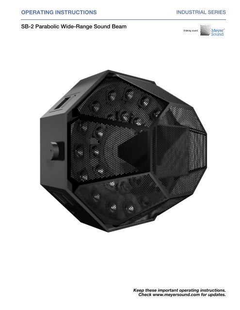
<strong>SB</strong>-2 Parabolic Wide-Range <strong>Sound</strong> Beam<br />
<br />
<br />
Keep these important operating instructions.<br />
Check www.meyersound.com for updates.
© 2013<br />
<strong>Meyer</strong> <strong>Sound</strong>. All rights reserved.<br />
<strong>SB</strong>-2 <strong>Operating</strong> <strong>Instructions</strong>, PN 05.108.015.01 A<br />
The contents of this manual are furnished for informational purposes only, are subject to change without notice, and should not be construed<br />
as a commitment by <strong>Meyer</strong> <strong>Sound</strong> Laboratories Inc. <strong>Meyer</strong> <strong>Sound</strong> assumes no responsibility or liability for any errors or inaccuracies<br />
that may appear in this manual. Except as permitted by applicable copyright law, no part of this publication may be reproduced,<br />
stored in a retrieval system, or transmitted, in any form or by any means, electronic, mechanical, recording or otherwise, without prior written<br />
permission from <strong>Meyer</strong> <strong>Sound</strong>.<br />
Compass RMS, Intelligent AC, QuietCool, RMS, <strong>SB</strong>-2, and all alpha-numeric designations for <strong>Meyer</strong> <strong>Sound</strong> products and accessories are<br />
trademarks of <strong>Meyer</strong> <strong>Sound</strong>. Compass, MAPP Online Pro, <strong>Meyer</strong> <strong>Sound</strong>, the <strong>Meyer</strong> <strong>Sound</strong> wave logo, and SIM are registered trademarks<br />
of <strong>Meyer</strong> <strong>Sound</strong> Laboratories Inc. (Reg. U.S. Pat. & Tm. Off.). All third-party trademarks mentioned herein are the property of their respective<br />
trademark holders.<br />
ii
SAFETY INSTRUCTIONS FOR LOUDSPEAKERS/ELECTRONICS<br />
SYMBOLS USED<br />
These symbols indicate important safety or operating features in this booklet and on the chassis:<br />
!<br />
Dangerous voltages: risk of<br />
electric shock<br />
Important operating<br />
instructions<br />
Frame or chassis<br />
Protective earth ground<br />
Pour indiquer les risques<br />
résultant de tensions<br />
dangereuses<br />
Pour indequer important<br />
instructions<br />
Masse, châssis<br />
Terre de protection<br />
Zu die gefahren von<br />
gefährliche spanning<br />
zeigen<br />
Zu wichtige betriebsanweisung<br />
und unterhaltsanweisung<br />
zeigen<br />
Rahmen oder chassis<br />
Die schutzerde<br />
Para indicar voltajes<br />
peligrosos<br />
Instrucciones importantes<br />
de funcionamiento y/o<br />
manteniento<br />
Armadura o chassis<br />
Tierra proteccionista<br />
IMPORTANT SAFETY INSTRUCTIONS<br />
1. Read these instructions.<br />
2. Keep these instructions.<br />
3. Heed all warnings.<br />
4. Follow all instructions.<br />
5. Do not use this apparatus near water.<br />
6. Clean only with dry cloth.<br />
7. Do not block any ventilation openings. Install in accordance<br />
with <strong>Meyer</strong> <strong>Sound</strong>’s installation instructions.<br />
8. Do not install near any heat sources such as radiators,<br />
heat registers, stoves, or other apparatus that produce<br />
heat.<br />
9. Do not defeat the safety purpose of the grounding-type<br />
plug. A grounding-type plug has two blades and a third<br />
grounding prong. The third prong is provided for your<br />
safety. If the provided plug does not fit into your outlet,<br />
consult an electrician for replacement of the obsolete<br />
outlet.<br />
10. Protect the power cord from being walked on or pinched,<br />
particularly at plugs, convenience receptacles, and the<br />
point where they exit from the apparatus. The AC mains<br />
plug or appliance coupler shall remain readily accessible<br />
for operation.<br />
11. Only use attachments/accessories specified by<br />
<strong>Meyer</strong> <strong>Sound</strong>.<br />
12. Use only with the caster rails or rigging specified by<br />
<strong>Meyer</strong> <strong>Sound</strong>, or sold with the apparatus. Handles are<br />
for carrying only.<br />
13. Unplug this apparatus during lightning storms or when<br />
unused for long periods of time.<br />
14. Refer all servicing to qualified service personnel. Servicing<br />
is required when the apparatus has been damaged in<br />
any way, such as when the power-supply cord or plug<br />
has been damaged; liquid has been spilled or objects<br />
have fallen into the apparatus; rain or moisture has<br />
entered the apparatus; the apparatus has been dropped;<br />
or when for undetermined reasons the apparatus does<br />
not operate normally.<br />
WARNING: To reduce the risk of electric<br />
!<br />
shock, do not expose this apparatus to rain or<br />
moisture. Do not install the apparatus in wet or humid<br />
locations without using weather protection equipment<br />
from <strong>Meyer</strong> <strong>Sound</strong>.<br />
POWERCON USE CAUTION<br />
Disconnect the mains plug before disconnecting the power<br />
cord from the speaker.<br />
iii
SAFETY INSTRUCTIONS FOR LOUDSPEAKERS/ELECTRONICS<br />
ENGLISH<br />
■<br />
■<br />
■<br />
■<br />
■<br />
■<br />
To reduce the risk of electric shock, disconnect<br />
the apparatus from the AC<br />
mains before installing audio cable.<br />
Reconnect the power cord only after<br />
making all signal connections.<br />
Connect the apparatus to a two-pole,<br />
three-wire grounding mains receptacle.<br />
The receptacle must be connected to a<br />
fuse or circuit breaker. Connection to<br />
any other type of receptacle poses a<br />
shock hazard and may violate local<br />
electrical codes.<br />
Do not install the apparatus in wet or<br />
humid locations without using weather<br />
protection equipment from<br />
<strong>Meyer</strong> <strong>Sound</strong>.<br />
Do not allow water or any foreign object<br />
to get inside the apparatus. Do not put<br />
objects containing liquid on or near the<br />
unit.<br />
To reduce the risk of overheating the<br />
apparatus, avoid exposing it to direct<br />
sunlight. Do not install the unit near<br />
heat-emitting appliances, such as a<br />
room heater or stove.<br />
This apparatus contains potentially hazardous<br />
voltages. Do not attempt to disassemble<br />
the unit. The unit contains no<br />
user-serviceable parts. Repairs should<br />
be performed only by factory-trained<br />
service personnel.<br />
FRANÇAIS<br />
■<br />
■<br />
■<br />
Pour réduire le risque d’électrocution,<br />
débrancher la prise principale de l’hautparleur,<br />
avant d’installer le câble d’interface<br />
allant à l’audio. Ne rebrancher le bloc<br />
d’alimentation qu’après avoir effectué<br />
toutes les connections.<br />
Branchez l’haut-parleur dans une prise<br />
de courant à 3 dérivations (deux pôles<br />
et la terre). Cette prise doit être munie<br />
d’une protection adéquate (fusible ou<br />
coupe-circuit). Le branchement dans<br />
tout autre genre de prise pourrait<br />
entraîner un risque d’électrocution et<br />
■<br />
■<br />
■<br />
■<br />
peut constituer une infraction à la réglementation<br />
locale concernant les installations<br />
électriques.<br />
Ne pas installer l’haut-parleur dans un<br />
endroit où il y a de l’eau ou une<br />
humidité excessive.<br />
Ne pas laisser de l’eau ou tout objet<br />
pénétrer dans l’haut-parleur. Ne pas<br />
placer de r´cipients contenant un liquide<br />
sur cet appareil, ni à proximité de celuici.<br />
Pour éviter une surchauffe de l’hautparleur,<br />
conserver-la à l’abri du soleil. Ne<br />
pas installer à proximité d’appareils<br />
dégageant de la chaleur tels que radiateurs<br />
ou appareils de chauffage.<br />
Ce haut-parleur contient des circuits<br />
haute tension présentant un danger. Ne<br />
jamais essayer de le démonter. Il n’y a<br />
aucun composant qui puisse être<br />
réparé par l’utilisateur. Toutes les réparations<br />
doivent être effectuées par du<br />
personnel qualifié et agréé par le constructeur.<br />
DEUTSCH<br />
■<br />
■<br />
■<br />
Um die Gefahr eines elektrischen<br />
Schlages auf ein Minimum zu reduzieren,<br />
den Lautsprecher vom Stromnetz<br />
trennen, bevor ggf. ein Audio-Schnittstellensign<br />
alkabel angeschlossen wird.<br />
Das Netzkabel erst nach Herstellung<br />
aller Signalverbindungen wieder einstecken.<br />
Der Lautsprecher an eine geerdete<br />
zweipolige Dreiphasen-Netzsteckdose<br />
anschließen. Die Steckdose muß mit<br />
einem geeigneten Abzweigschutz<br />
(Sicherung oder Leistungsschalter) verbunden<br />
sein. Der Anschluß der unterbrechungsfreien<br />
Stromversorgung an<br />
einen anderen Steckdosentyp kann zu<br />
Stromschlägen führen und gegen die<br />
örtlichen Vorschriften verstoßen.<br />
Der Lautsprecher nicht an einem Ort<br />
aufstellen, an dem sie mit Wasser oder<br />
übermäßig hoher Luftfeuchtigkeit in<br />
Berührung kommen könnte.<br />
■<br />
■<br />
■<br />
Darauf achten, daß weder Wasser noch<br />
Fremdkörper in das Innere den<br />
Lautsprecher eindringen. Keine<br />
Objekte, die Flüssigkeit enthalten, auf<br />
oder neben die unterbrechungsfreie<br />
Stromversorgung stellen.<br />
Um ein Überhitzen dem Lautsprecher<br />
zu verhindern, das Gerät vor direkter<br />
Sonneneinstrahlung fernhalten und<br />
nicht in der Nähe von wärmeabstrahlenden<br />
Haushaltsgeräten (z.B. Heizgerät<br />
oder Herd) aufstellen.<br />
Im Inneren diesem Lautsprecher herrschen<br />
potentiell gefährliche Spannungen.<br />
Nicht versuchen, das Gerät zu öffnen.<br />
Es enthält keine vom Benutzer<br />
reparierbaren Teile. Reparaturen dürfen<br />
nur von ausgebildetem Kundenienstpersonal<br />
durchgeführt werden.<br />
ESPAÑOL<br />
■<br />
■<br />
■<br />
■<br />
■<br />
Para reducir el riesgo de descarga eléctrica,<br />
desconecte de la red de voltaje el<br />
altoparlante antes de instalar el cable<br />
de señal de audio. Vuelva a conectar la<br />
alimentacion de voltaje una vez efectuadas<br />
todas las interconexiones de<br />
señalizacion de audio.<br />
Conecte el altoparlante a un tomacorriente<br />
bipolar y trifilar con neutro de<br />
puesta a tierra. El tomacorriente debe<br />
estar conectado a la protección de derivación<br />
apropiada (ya sea un fusible o un<br />
disyuntor). La conexión a cualquier otro<br />
tipo de tomacorriente puede constituir<br />
peligro de descarga eléctrica y violar los<br />
códigos eléctricos locales.<br />
No instale el altoparlante en lugares<br />
donde haya agua o humedad excesiva.<br />
No deje que en el altoparlante entre<br />
agua ni ningún objeto extraño. No<br />
ponga objetos con líquidos encima de<br />
la unidad ni cerca de ella.<br />
Para reducir el riesgo de sobrecalentamiento,<br />
no exponga la unidad a los<br />
rayos directos del sol ni la instale cerca<br />
de artefactos que emiten calor, como<br />
estufas o cocinas.<br />
iv
FEDERAL COMMUNICATIONS COMMISSION (FCC) STATEMENT<br />
This equipment has been tested and found to comply with the limits for a Class A digital device, pursuant to part 15 of the<br />
FCC Rules. These limits are designed to provide reasonable protection against harmful interference when the equipment is<br />
operated in a commercial environment. This equipment generates, uses, and can radiate radio frequency energy and, if not<br />
installed and used in accordance with the instruction manual, may cause harmful interference to radio communications.<br />
Operation of this equipment in a residential area is likely to cause harmful interference in which case the user will be required<br />
to correct the interference at their own expense.<br />
This device complies with Part 15 of the FCC rules. Operation is subject to the following two conditions: (1) this device may<br />
not cause harmful interference, and (2) this device must accept any interference received, including interference that may<br />
cause undesired operation.<br />
INDUSTRY CANADA COMPLIANCE STATEMENT<br />
This Class A digital apparatus complies with Canadian ICES-003.<br />
AVIS DE CONFORMITÉ À LA RÉGLEMENTATION D'INDUSTRIE CANADA<br />
Cet appareil numérique de la classe A est conforme à la norme NMB-003 du Canada.<br />
v
CONTENTS<br />
Chapter 1: Introduction 9<br />
How to Use This Manual 9<br />
<strong>SB</strong>-2 Parabolic Wide-Range <strong>Sound</strong> Beam 9<br />
<strong>SB</strong>-2 Rigging Options 10<br />
Chapter 2: Power Requirements 11<br />
AC Connector 11<br />
Wiring AC Power Cables 11<br />
AC Power Distribution 12<br />
<strong>SB</strong>-2 Voltage Requirements 12<br />
<strong>SB</strong>-2 Current Requirements 12<br />
Powering Up the <strong>SB</strong>-2 13<br />
Electrical Safety Guidelines 13<br />
Chapter 3: Amplification and Audio 15<br />
Audio Connections with VEAM Cabling 15<br />
Audio Connectors 15<br />
Limiting 16<br />
Input Polarity Switch 17<br />
Amplifier Cooling System 17<br />
Calibration & TEst Port 18<br />
Chapter 4: RMS Remote Monitoring System 19<br />
Compass RMS Software 19<br />
RMS Module 20<br />
Resetting the RMS Module 20<br />
Chapter 5: System Design and Integration Tools 21<br />
MAPP Online PRO 21<br />
SIM 3 Measurement System 22<br />
Appendix A: <strong>SB</strong>-2 Specifications 23<br />
<strong>SB</strong>-2 Dimensions 25<br />
<strong>SB</strong>-2 Compliance 25<br />
vii
CONTENTS<br />
viii
CHAPTER 1: INTRODUCTION<br />
HOW TO USE THIS MANUAL<br />
Make sure to read these operating instructions in their<br />
entirety before configuring a loudspeaker system with<br />
<strong>SB</strong>-2s. In particular, pay close attention to material related to<br />
safety issues.<br />
As you read these operating instructions, you will encounter<br />
the following icons for notes, tips, and cautions:<br />
<strong>SB</strong>-2 PARABOLIC WIDE-RANGE<br />
SOUND BEAM<br />
The <strong>SB</strong>-2 is a bi-amplified sound reinforcement loudspeaker<br />
housed in an octagonal enclosure with a parabolic dish front<br />
face. Capable of high sound pressure levels with precisely<br />
defined narrow coverage, the <strong>SB</strong>-2 offers a unique solution<br />
for large-scale distributed paging and music systems.<br />
NOTE: A note identifies an important or useful<br />
piece of information relating to the topic under<br />
discussion.<br />
TIP: A tip offers a helpful tip relevant to the topic<br />
at hand.<br />
CAUTION: A caution gives notice that an<br />
!<br />
action may have serious consequences and<br />
could cause harm to equipment or personnel, or<br />
could cause delays or other problems.<br />
Information and specifications are subject to change.<br />
Updates and supplementary information are available at<br />
www.meyersound.com.<br />
<strong>Meyer</strong> <strong>Sound</strong> Technical Support is available at:<br />
■ Tel: +1 510 486.1166<br />
■<br />
■<br />
■<br />
Tel: +1 510 486.0657 (after hours support)<br />
Web: www.meyersound.com/support<br />
Email: techsupport@meyersound.com<br />
<strong>SB</strong>-2 Parabolic Wide-Range <strong>Sound</strong> Beam<br />
While distributed ceiling loudspeakers are often employed in<br />
an attempt to overcome reverberation and improve intelligibility,<br />
large venues pose problems of scale that conventional<br />
ceiling loudspeakers cannot effectively address. In applications<br />
where the ceiling height is 40 feet or more, a conventional<br />
distributed system lacks both the power to overcome<br />
air losses and the directionality to avoid combing and<br />
excessive reverberation.<br />
The <strong>SB</strong>-2 provides a unique and effective solution to these<br />
problems. Featuring a tight 20-degree coverage pattern with<br />
high output capability, the <strong>SB</strong>-2 offers the ability to cover<br />
individual zones with highly intelligible, full-range sound<br />
while avoiding overlapping. A hybrid two-way system, the<br />
<strong>SB</strong>-2 uses a waveguide to achieve directionality at high frequencies<br />
and a parabolic array of cone drivers at mid-to-low<br />
frequencies. The result is tightly controlled coverage from<br />
500 Hz to 16 kHz with low-frequency response extending<br />
down to 130 Hz.<br />
9
CHAPTER 1: INTRODUCTION<br />
The <strong>SB</strong>-2 is comprised of 28 4-inch cone drivers, a single 2-<br />
inch throat, 4-inch diaphragm compression driver, an integral<br />
complementary MOSFET power amplifier with 1240 W<br />
burst capability, and optimized signal processing circuitry. It<br />
features options for L6-20, IEC 309, and VEAM all-in-one<br />
AC connectors, as well as compatibility with <strong>Meyer</strong> <strong>Sound</strong>’s<br />
RMS remote monitoring system.<br />
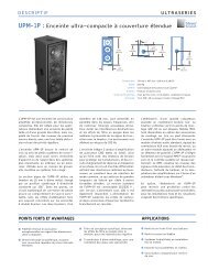
<strong>SB</strong>-2 RIGGING OPTIONS<br />
The <strong>SB</strong>-2 supports the following rigging options:<br />
■<br />
■<br />
■<br />
MYA-<strong>SB</strong>-2 yoke assembly kit — suspends a single <strong>SB</strong>-2.<br />
VAK-<strong>SB</strong>-2 vertical array kit — vertically links two <strong>SB</strong>-2s<br />
equipped with MYA-<strong>SB</strong>-2 yokes. Multiple VAK-<strong>SB</strong>-2<br />
array kits can be used to construct vertical arrays with<br />
multiple <strong>SB</strong>-2s: up to 14 units at a 5:1 safety factor, or up<br />
to 10 units at a 7:1 safety factor.<br />
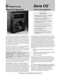
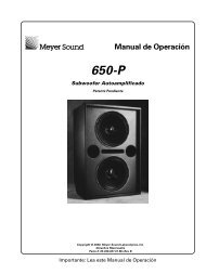
HAK-<strong>SB</strong>-2 horizontal array kit — horizontally links two<br />
<strong>SB</strong>-2s equipped with MYA-<strong>SB</strong>-2 yokes at 0-, 15-, or 20-<br />
degree angles. Multiple HAK-<strong>SB</strong>-2 array kits can be used<br />
to construct horizontal arrays with multiple <strong>SB</strong>-2s.<br />
HAK-<strong>SB</strong>-2 Horizontal Array with Two <strong>SB</strong>-2s<br />
NOTE: For more information on <strong>SB</strong>-2 rigging<br />
hardware, including configuration and load ratings,<br />
refer to the MYA-<strong>SB</strong>-2 Assembly Guide<br />
(PN 05.108.400.01) available at<br />
www.meyersound.com.<br />
10
CHAPTER 2: POWER REQUIREMENTS<br />
The <strong>SB</strong>-2 combines advanced loudspeaker technology with<br />
equally advanced power capabilities. Understanding power<br />
distribution, voltage and current requirements, and electrical<br />
safety guidelines is critical to the safe operation of the <strong>SB</strong>-2.<br />
AC CONNECTOR<br />
The <strong>SB</strong>-2 AC connector supplies AC power to the unit and is<br />
located on its rear user panel. The <strong>SB</strong>-2 can be equipped<br />
with either a NEMA L6-20 (twistlock) male inlet, IEC 309<br />
male inlet, or VEAM all-in-one connector.<br />
The <strong>SB</strong>-2 requires a grounded outlet. To operate safely and<br />
effectively, it is extremely important that the entire system be<br />
properly grounded.<br />
If you replace the included AC power cable, make sure to<br />
use a cable that is wired correctly and equipped with the<br />
with the appropriate power plug (on the other end) for the<br />
area in which you will operate the unit.<br />
NOTE: For wiring conventions for the VEAM<br />
all-in-one connector (AC, audio, and RMS),<br />
refer to the VEAM Cable Wiring Reference<br />
(PN 06.033.113.01) document available from<br />
www.meyersound.com.<br />
Neutral<br />
(blue)<br />
NEMA L6-20 (Twistlock) Male Inlet<br />
X-neutral<br />
(blue)<br />
IEC 309 Male Inlet Connector<br />
Line (brown)<br />
Ground <br />
(green/yellow)<br />
Ground <br />
(green/yellow)<br />
Y-line (brown)<br />
WIRING AC POWER CABLES<br />
When wiring AC power cables, use the following wiring<br />
scheme:<br />
U.S. /<br />
Canada /<br />
60 Hz<br />
(blk) L<br />
AC Cable Wiring Scheme<br />
U.S. / Canada /<br />
60 Hz<br />
(wht) N<br />
(grn) E<br />
Wire Color<br />
European /<br />
50 Hz<br />
(brn) L<br />
Europe /<br />
50 Hz<br />
(blu) N<br />
(grn/y) E<br />
Attach to<br />
Following<br />
Terminal<br />
Black Brown Hot or live (L)<br />
White Blue Neutral (N)<br />
Green Green and Yellow Protective earth /<br />
ground (E or PE))<br />
X-neutral<br />
(blue)<br />
VEAM All-In-One Connector<br />
Ground <br />
(green/yellow)<br />
Y-line (brown)<br />
CAUTION: When creating AC power cables<br />
!<br />
and distribution systems, it is important to preserve<br />
AC line polarity and connect the earth ground<br />
on both ends of the cable. <strong>SB</strong>-2 requires a grounded<br />
connection. Always use a grounded outlet and plug.<br />
It is extremely important that the system be properly<br />
grounded to operate safely and properly. Do not<br />
ground-lift the AC cable.<br />
11
CHAPTER 2: POWER REQUIREMENTS<br />
AC POWER DISTRIBUTION<br />
All components in an audio system (self-powered loudspeakers,<br />
mixing consoles, and processors) must be properly<br />
connected to an AC power distribution system, ensuring<br />
that AC line polarity is preserved and that all grounding<br />
points are connected to a single node or common point<br />
using the same cable gauge as the neutral and line cables.<br />
NOTE: Improper grounding of connections<br />
between loudspeakers and the rest of the<br />
audio system may produce noise or hum, or cause<br />
serious damage to the input and output stages of the<br />
system’s electronic components.<br />
CAUTION: Before applying AC power to any<br />
!<br />
<strong>Meyer</strong> <strong>Sound</strong> self-powered loudspeaker, make<br />
sure that the voltage potential difference between the<br />
neutral and earth-ground lines is less than 5 V AC.<br />
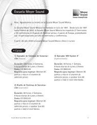
Figure 1 illustrates a basic three-phase AC distribution system<br />
with the loudspeaker load distributed across the three<br />
phases. All loudspeakers are connected to common neutral<br />
and earth-ground lines.<br />
Line 1 Line 2 Line 3 Neutral<br />
Figure 1: AC Power Distribution System<br />
Earth Ground<br />
<strong>SB</strong>-2 VOLTAGE REQUIREMENTS<br />
The <strong>SB</strong>-2 operates safely and continuously when the AC<br />
voltage stays within 85–134 V AC and 165–264 V AC at 50<br />
or 60 Hz. The loudspeaker allows any combination of voltage<br />
to GND (neutral-line-ground or line-line-ground).<br />
If the voltage drops below 85 V (brownout), the <strong>SB</strong>-2 uses<br />
stored power to continue operating temporarily; the loudspeaker<br />
shuts down if the voltage does not rise above the<br />
low boundary before the stored power is used.<br />
If the voltage rises above 275 V, the power supply could<br />
become damaged.<br />
CAUTION: The power source for the <strong>SB</strong>-2<br />
!<br />
should always operate within the required voltage<br />
range, at least a few volts from the upper and<br />
lower ranges. This will ensure that AC voltage variations<br />
from the service entry — or peak voltage drops<br />
due to cable runs — will not cause the loudspeaker’s<br />
amplifier to cycle on and off or cause damage to the<br />
power supply.<br />
TIP: Since the <strong>SB</strong>-2 does not require a dedicated<br />
neutral line, and it can tolerate elevated<br />
voltages from the ground line, it can be connected to<br />
line-line terminals in 120 V, 3-phase Wye systems.<br />
This results in 208 V AC between lines (nominal) and<br />
therefore draws less current than when using 120 V<br />
AC (line-neutral). Make sure that the voltage remains<br />
within the <strong>SB</strong>-2’s recommended operating windows<br />
(85–134 V AC and 165–264 V AC). The ground line<br />
must always be used for safety reasons and the lineto-ground<br />
voltage should never exceed 250 V AC<br />
(typically 120 V AC from line-to-ground).<br />
<strong>SB</strong>-2 CURRENT REQUIREMENTS<br />
The current draw for the <strong>SB</strong>-2 is dynamic and fluctuates as<br />
operating levels change. Since different cables and circuit<br />
breakers heat up at varying rates, it is important to understand<br />
the following types of current ratings and how they<br />
affect circuit breaker and cable specifications.<br />
■<br />
■<br />
■<br />
■<br />
■<br />
Idle Current — The maximum rms current during idle<br />
periods.<br />
Maximum Long-Term Continuous Current — The<br />
maximum rms current during a period of at least 10 seconds.<br />
The Maximum Long-Term Continuous Current is<br />
used to calculate temperature increases for cables, to<br />
ensure that cable sizes and gauges conform to electrical<br />
code standards. The current rating is also used as a rating<br />
for slow-reacting thermal breakers.<br />
Burst Current — The maximum rms current during a<br />
period of around one second. The Burst Current is used<br />
as a rating for magnetic breakers. It is also used for calculating<br />
the peak voltage drop in long AC cable runs<br />
according to the following formula:<br />
V pk (drop) = I pk x R (cable total)<br />
Ultimate Short-Term Peak Current — A rating for fastreacting<br />
magnetic breakers.<br />
Inrush Current — The spike of initial current encountered<br />
when powering on.<br />
12
<strong>SB</strong>-2 OPERATING INSTRUCTIONS<br />
You can use Table 1 as a guide for selecting cable gauges<br />
and circuit breaker ratings for the system’s operating voltage.<br />
Table 1: <strong>SB</strong>-2 Current Draw<br />
Current Draw 115 V AC 230 V AC 100 V AC<br />
Maximum Long-Term<br />
Continuous Current<br />
The minimum electrical service amperage required by an<br />
<strong>SB</strong>-2 loudspeaker system is the sum of the Maximum Long-<br />
Term Continuous Current for each loudspeaker. An additional<br />
30 percent above the minimum amperage is recommended<br />
to prevent peak voltage drops at the service entry.<br />
NOTE: For best performance, the AC cable<br />
voltage drop should not exceed 10 V, or<br />
10 percent at 115 V and 5 percent at 230 V. Make<br />
sure that even with AC voltage drops that the AC<br />
voltage always remains within the operating windows.<br />
POWERING UP THE <strong>SB</strong>-2<br />
When AC power is applied to the <strong>SB</strong>-2 its Intelligent AC<br />
power supply automatically selects the correct operating<br />
voltage, allowing it to be used internationally without manually<br />
setting voltage switches. In addition, Intelligent AC suppresses<br />
high-voltage transients up to several kilovolts, filters<br />
common mode and differential mode radio frequencies<br />
(EMI), and sustains operation temporarily during low-voltage<br />
periods.<br />
When powering up the <strong>SB</strong>-2, the following startup events<br />
take place over several seconds.<br />
1. Audio output is muted.<br />
2. Voltage is detected and the power supply mode is automatically<br />
adjusted as necessary.<br />
3. The primary fan turns on.<br />
4. The power supply ramps up.<br />
8 A rms 4 A rms 10 A rms<br />
Burst Current 15 A rms 8 A rms 18 A rms<br />
Maximum Instantaneous<br />
Peak Current<br />
22 A peak 11 A peak 25 A peak<br />
Inrush Current
CHAPTER 2: POWER REQUIREMENTS<br />
14
CHAPTER 3: AMPLIFICATION AND AUDIO<br />
The <strong>SB</strong>-2’s drivers are powered by a 2-channel proprietary<br />
<strong>Meyer</strong> <strong>Sound</strong> amplifier with MOSFET output stages. The<br />
audio signal is processed with an electronic crossover, correction<br />
filters for phase and frequency responses, and driver<br />
protection circuitry. Each channel has peak and rms limiters<br />
that prevent driver over-excursion and regulate voice coil<br />
temperatures.<br />
AUDIO CONNECTORS<br />
The <strong>SB</strong>-2 include female XLR Input and male XLR Loop output<br />
connectors.<br />
10K <br />
Balanced<br />
Input Polarity<br />
2 +<br />
3 +<br />
ESD<br />
1<br />
220K <br />
Case<br />
2<br />
3<br />
1 1 2<br />
3<br />
Earth / Chassis<br />
Input<br />
Loop<br />
CAUTION<br />
WARNINGS:<br />
RISK OF ELECTRIC SHOCK<br />
DO NOT OPEN<br />
!<br />
<strong>SB</strong>-2 Audio Connectors, Input and Loop Output<br />
This product must be grounded.<br />
This surface may reach high temperatures while in use.<br />
To ensure proper operation, allow at least 6 inches<br />
clearance from this surface and adequate ventilation.<br />
No operator serviceable parts inside.<br />
Refer servicing to qualified personnel.<br />
To reduce the risk of fire or electric shock<br />
do not expose this appliance to rain or moisture.<br />
Input Connector<br />
<strong>SB</strong>-2<br />
HI Limit<br />
LO Limit<br />
Active<br />
Input Polarity<br />
2 +<br />
3 +<br />
10K <br />
Balanced<br />
1<br />
ESD<br />
220K <br />
2<br />
Case<br />
Earth / Chassis<br />
3<br />
1 1 2<br />
3<br />
Input<br />
R E<br />
R E<br />
P<br />
-<br />
P<br />
-<br />
Loop<br />
USH<br />
C<br />
10<br />
I<br />
R K<br />
USH<br />
C<br />
10<br />
I<br />
- I T<br />
- I T<br />
R K<br />
Service<br />
Wink<br />
Reset<br />
Activity<br />
Network<br />
Remote Monitor System<br />
NID: 001848623900<br />
ATENCIÓN: ACCESO INTERNO SOLO<br />
AUTORIZADO A PERSONAL TÉCNICO CALIFICADO<br />
ACHTUNG: GEHÄUSE NICHT ÖFFNEN WARTUNG<br />
UND REPARATUR NUR DURCH ELEKTROFACHKRÄFTE<br />
ATTENTION: ENTRETIEN ET REPARATIONS<br />
INTERNES NE SONT AUTORISEES QU'AU<br />
PERSONNEL TECHNIQUE QUALIFIÉ<br />
UK WARNING:<br />
THIS APPARATUS MUST BE EARTHED.<br />
NO OPERATOR SERVICEABLE PARTS INSIDE.<br />
REFER SERVICING TO QUALIFIED PERSONNEL<br />
ME<br />
RMS3<br />
Firmware<br />
Auto-Voltage Select<br />
95-125V~ 208-235V~<br />
50-60Hz<br />
50-60Hz<br />
1400W RMS MAX 1400W RMS MAX<br />
Operational Voltage Range:<br />
Turn on 85V~ Turn off 134V~<br />
Turn on 165V~ Turn off 264V~<br />
<strong>Meyer</strong> <strong>Sound</strong>, Berkeley, CA. USA<br />
The female XLR Input connector accepts a balanced audio<br />
signal with an input impedance of 10 kOhm. The connector<br />
uses the following wiring:<br />
■<br />
Pin 1 — 220 kOhm to chassis and earth ground (ESD<br />
clamped)<br />
■ Pin 2 — Signal (+)<br />
■ Pin 3 — Signal (–)<br />
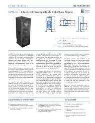
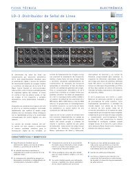
<strong>SB</strong>-2 Rear Panel (with NEMA L6-20 AC Connector)<br />
The <strong>SB</strong>-2 rear panel includes audio connectors for Input and<br />
Loop output, as well as an Input Polarity switch. The <strong>SB</strong>-2 is<br />
also available with an optional RMS module (see Chapter 4,<br />
“RMS Remote Monitoring System”).<br />
AUDIO CONNECTIONS WITH VEAM CABLING<br />
The <strong>SB</strong>-2 can be ordered from the factory with a VEAM allin-one<br />
connector. VEAM connectors consolidate AC power,<br />
audio, and RMS into a single cable, facilitating easy connections<br />
and quick setups.<br />
For wiring conventions for the VEAM all-in-one connector<br />
(AC, audio, and RMS), refer to the VEAM Cable Wiring Reference<br />
(PN 06.033.113.01) document available from<br />
www.meyersound.com.<br />
■<br />
Case — Earth (AC) ground and chassis<br />
Pins 2 and 3 carry the input as a differential signal. Pin 1 is<br />
connected to earth through a 220 kOhm, 1000 pF, 15 V<br />
clamped network. This circuitry provides virtual ground lift<br />
for audio frequencies while allowing unwanted signals to<br />
bleed to ground. Make sure to use standard, balanced XLR<br />
audio cables with all three pins connected on both ends.<br />
Telescopic grounding is not recommended, and shorting an<br />
input connector pin to the case may cause a ground loop,<br />
resulting in hum.<br />
TIP: If unwanted noise or hiss is produced by<br />
the loudspeaker, disconnect its input cable. If<br />
the noise stops, there is most likely nothing wrong<br />
with the loudspeaker. To locate the source of the<br />
noise, check the audio cable, source audio, and AC<br />
power.<br />
15
CHAPTER 3: AMPLIFICATION AND AUDIO<br />
Loop Output Connector<br />
The male XLR Loop output connector allows <strong>SB</strong>-2 loudspeakers<br />
to be looped from a single audio source. For applications<br />
that require multiple <strong>SB</strong>-2s, connect the Loop<br />
output of the first unit to the Input of the second, and so<br />
forth.<br />
NOTE: The order in which loudspeakers are<br />
connected when looping audio signals is unimportant.<br />
The Loop connector is wired in parallel to the<br />
Input connector and transmits the unbuffered source<br />
signal even when the <strong>SB</strong>-2 is powered off.<br />
To avoid distortion when looping multiple <strong>SB</strong>-2s, make sure<br />
the source device can drive the total load impedance of the<br />
looped loudspeakers. In addition, the source device must be<br />
capable of delivering approximately 20 dBV (10 V rms into<br />
600 ohms) to yield the maximum peak SPL over the entire<br />
operating bandwidth of the loudspeakers. Most professional<br />
audio equipment can transmit these source levels.<br />
To calculate the load impedance for the looped loudspeakers,<br />
divide 10 kOhms (the input impedance for a single<br />
<strong>SB</strong>-2) by the number of looped loudspeakers. For example,<br />
the load impedance for 10 <strong>SB</strong>-2 loudspeakers is 1000 ohms<br />
(10 kOhms / 10). To drive this number of looped loudspeakers,<br />
the source device should have an output impedance of<br />
100 ohms or less. This same rule applies when looping<br />
<strong>SB</strong>-2s with other self-powered <strong>Meyer</strong> <strong>Sound</strong> loudspeakers<br />
and subwoofers.<br />
NOTE: Most source devices are capable of<br />
driving loads no smaller than 10 times their<br />
output impedance.<br />
CAUTION: Make sure that all cabling for<br />
!<br />
looped loudspeakers is wired correctly (Pin 1<br />
to Pin 1, Pin 2 to Pin 2, and so forth) to prevent the<br />
polarity from being reversed. If one or more loudspeakers<br />
in a system have reversed polarity, frequency<br />
response and coverage will be significantly<br />
degraded.<br />
LIMITING<br />
The <strong>SB</strong>-2 employs <strong>Meyer</strong> <strong>Sound</strong>’s advanced TruPower ® limiting.<br />
Conventional limiters assume a constant loudspeaker<br />
impedance and set the limiting threshold by measuring voltage<br />
alone. This method is inaccurate because loudspeaker<br />
impedances change as frequency content in the source<br />
material changes, and as thermal values for the loudspeaker’s<br />
voice coil and magnet vary. Consequently, conventional<br />
limiters often begin limiting prematurely, which reduces<br />
system headroom and dynamic range.<br />
<strong>SB</strong>-2<br />
HI Limit<br />
LO Limit<br />
Active<br />
<strong>SB</strong>-2 Limit LEDs<br />
In contrast, TruPower limiting anticipates varying loudspeaker<br />
impedances by measuring both current and voltage<br />
to compute the actual power dissipation in the voice coil.<br />
This improves performance, both before and during limiting,<br />
by allowing the driver to produce the maximum SPL across<br />
its entire frequency range. TruPower limiting also eliminates<br />
power compression at high levels over lengthy periods,<br />
which helps regulate voice coil temperatures, thereby<br />
extending the life of the driver.<br />
NOTE: Since TruPower limiting only reduces<br />
signal levels to keep voice coil temperatures<br />
under a safe margin, signal peaks remain unaffected.<br />
HI Limit LED<br />
The low- and high-frequency drivers for the <strong>SB</strong>-2 are powered<br />
by separate amplifier channels, each with their own<br />
limiter. Limiting activity is indicated with the two Limit LEDs.<br />
The HI Limit LED indicates limiting for the high-frequency<br />
channel and the LO Limit LED indicates limiting for the lowfrequency<br />
channel.<br />
When engaged, the limiter not only protects the drivers but<br />
also prevents signal peaks from causing excessive distortion<br />
in the amplifier channels, thereby preserving headroom<br />
and maintaining smooth frequency responses at high levels.<br />
When levels returns to normal, below the limiter thresholds,<br />
limiting ceases.<br />
16
<strong>SB</strong>-2 OPERATING INSTRUCTIONS<br />
The <strong>SB</strong>-2 performs within its acoustical specifications at<br />
normal temperatures when the Limit LEDs are unlit, or when<br />
an LED is lit for 2 seconds or less and then turns off for at<br />
least 1 second. If an LED remains lit for longer than<br />
3 seconds, the loudspeaker enters hard limiting where:<br />
■<br />
■<br />
■<br />
Increases to the input level have no effect.<br />
Distortion increases due to clipping and nonlinear driver<br />
operation.<br />
The drivers are subjected to excessive heat and excursion,<br />
which will compromise their life span and may<br />
eventually lead to damage over time.<br />
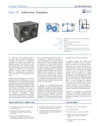
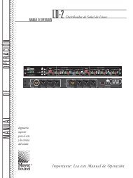
AMPLIFIER COOLING SYSTEM<br />
The <strong>SB</strong>-2 uses a forced-air cooling system with two fans<br />
(one variable-speed, ultra low-noise primary fan and one<br />
reserve fan) to prevent the amplifier module from overheating.<br />
The fans draw air in through ducts on the front of the<br />
cabinet, over the heat sink, and out the rear of the cabinet.<br />
Because dust does not accumulate in the amplifier circuitry,<br />
its life span is increased significantly.<br />
Power<br />
supply<br />
CAUTION: The Limit LEDs indicate when a<br />
!<br />
safe, optimum level has been exceeded. If an<br />
<strong>SB</strong>-2 begins to limit before reaching the required<br />
SPL, consider adding more units to the system.<br />
NOTE: The <strong>SB</strong>-2 loudspeaker uses optical limiters<br />
that add no noise and have no effect on<br />
the signal when the limiter is not engaged and the<br />
Limit LEDs are not lit.<br />
INPUT POLARITY SWITCH<br />
The <strong>SB</strong>-2 includes an Input Polarity switch on its rear panel<br />
that toggles the polarity of the source signal. When the<br />
switch is in the UP position, pin 2 is hot relative to pin 3,<br />
resulting in a positive pressure wave when a positive signal<br />
is applied to pin 2. When the switch is in the DOWN position,<br />
pin 3 is hot relative to pin 2, resulting in a positive pressure<br />
wave when a positive signal is applied to pin 3.<br />
Input Polarity<br />
2 +<br />
3 +<br />
10K <br />
Balanced<br />
1<br />
<strong>SB</strong>-2 Input Polarity Switch<br />
NOTE: The Input Polarity switch does not<br />
affect the signal coming from the Loop output<br />
connector. The Loop output connector is wired in<br />
parallel to the Input connector and transmits the<br />
unbuffered source signal (even when the loudspeaker<br />
is powered off).<br />
CAUTION: To keep the <strong>SB</strong>-2 from getting too<br />
!<br />
hot, allow for proper ventilation, at least<br />
6 inches, behind the loudspeaker.<br />
When the <strong>SB</strong>-2 heat sink temperature is below 42° C, the<br />
variable-speed primary fan runs continuously at its slowest<br />
speed with an inaudible operating noise. The primary fan<br />
increases speed when the heat sink temperature reaches<br />
42° C; the primary fan reaches full speed at 62° C and is<br />
barely audible near the cabinet, even without an audio signal.<br />
If the heat sink temperature reaches 74° C, the reserve<br />
fan turns on. The reserve fan turns on if:<br />
■<br />
■<br />
■<br />
Air<br />
intake<br />
Airflow for the <strong>SB</strong>-2<br />
Air filter<br />
Lownoise<br />
fans<br />
Heat sink/<br />
amplifier<br />
The primary fan has failed (check status immediately)<br />
High source levels are encountered for extended periods<br />
Dust has accumulated along the cooling path<br />
The reserve fan turns off when the heat sink temperature<br />
lowers to 68° C.<br />
NOTE: In the unlikely event that the reserve fan<br />
does not keep the <strong>SB</strong>-2 heat sink temperature<br />
below 85° C, the unit automatically shuts down until<br />
AC power is removed and reapplied. If the <strong>SB</strong>-2<br />
shuts down again after cooling and re-applying AC<br />
power, contact <strong>Meyer</strong> <strong>Sound</strong> for repair information.<br />
17
CHAPTER 3: AMPLIFICATION AND AUDIO<br />
Dust and the Amplifier Module<br />
<strong>Operating</strong> the <strong>SB</strong>-2 in dusty environments, or for prolonged,<br />
intensive periods, may cause dust to accumulate along its<br />
airflow path, thereby preventing normal cooling. Under these<br />
circumstances, it may be necessary to periodically remove<br />
the air intake foam and use compressed to air to clear the<br />
dust from the foam and air ducts.<br />
In addition, if the amplifier gets unusually hot, you should<br />
remove the amplifier module and use compressed air to<br />
clear any dust from its heat sink.<br />
!<br />
CAUTION: Make sure to unplug the AC power<br />
from the <strong>SB</strong>-2 before cleaning its amplifier.<br />
CALIBRATION & TEST PORT<br />
The <strong>SB</strong>-2 includes a Calibration & Test Port, located next to<br />
its user panel, that allows the unit’s 28 low-frequency drivers<br />
to be verified with the included DC test harness. For more<br />
information on the test procedure, refer to the <strong>SB</strong>-2 Service<br />
Information document (PN 17.108.140.01) available from<br />
<strong>Meyer</strong> <strong>Sound</strong> Technical Support.<br />
<strong>SB</strong>-2 Calibration & Test Port<br />
18
CHAPTER 4: RMS REMOTE MONITORING SYSTEM<br />
The <strong>SB</strong>-2 is optionally available with the RMS remote monitoring<br />
system module, allowing it to be connected to an<br />
RMS network. RMS reports, in real time, the status and<br />
power usage of multiple <strong>Meyer</strong> <strong>Sound</strong> loudspeakers from a<br />
Mac ® or Windows ® -based computer. The RMS host computer<br />
communicates with <strong>Meyer</strong> <strong>Sound</strong> loudspeakers<br />
(equipped with RMS modules) via RMServer, a compact,<br />
Ethernet-based hardware unit with two FT-10 ports that can<br />
network up to 50 RMS loudspeakers or twelve MPS-488HP<br />
external power supplies. RMServer stores system configurations<br />
internally, eliminating most manual data entry. Systems<br />
can be monitored from a laptop at front-of-house or backstage,<br />
or from a tablet computer anywhere within the venue<br />
over Wifi.<br />
COMPASS RMS SOFTWARE<br />
The optional Compass RMS software provides extensive<br />
system status and performance data for each loudspeaker,<br />
including amplifier voltage, limiting activity, power output,<br />
fan and driver status, as well as mute and solo capability.<br />
Loudspeakers are added to the RMS network and assigned<br />
a node name during a one-time commissioning procedure.<br />
Once loudspeakers are identified on the RMS network, they<br />
appear in the Compass RMS software as icons and data<br />
views that can be customized to suit your needs.<br />
NOTE: The <strong>SB</strong>-3F loudspeaker occupies the<br />
bandwidth of two normal loudspeakers on<br />
RMS networks. Therefore, a maximum of 25 <strong>SB</strong>-3F<br />
loudspeakers can be connected to single RMServer.<br />
NOTE: For the latest RMS system requirements,<br />
visit the <strong>Meyer</strong> <strong>Sound</strong> website <br />
(http://www.meyersound.com).<br />
NOTE: RMS-equipped loudspeakers include a<br />
Mute Jumper to enable the loudspeaker’s mute<br />
and solo capability. <strong>Meyer</strong> <strong>Sound</strong> currently ships<br />
RMS-equipped loudspeakers with the Mute Jumper<br />
installed. These mute-enabled loudspeakers can be<br />
identified by the blue “ME” sticker on the face of the<br />
RMS module. Older RMS-equipped loudspeakers<br />
can easily be mute-enabled by installing the Mute<br />
Jumper.<br />
NOTE: RMS does not control AC power.<br />
Compass RMS Window<br />
Loudspeaker data is updated 2–5 times per second. Individual<br />
loudspeakers can be physically identified with the Wink<br />
option in RMS, which lights the Wink LED on the RMS module<br />
for that particular loudspeaker. Conversely, a loudspeaker<br />
can be identified in the RMS software by pressing<br />
the Service button on the loudspeaker’s RMS module.<br />
Loudspeaker icons and data views can be arranged to represent<br />
how the loudspeakers have been deployed in the<br />
system. Multiple panels can be saved and recalled for specific<br />
performances and venues.<br />
NOTE: When the <strong>SB</strong>-2 heat sink reaches 85° C<br />
(185° F), the On/Temp LED turns red, while its<br />
loudspeaker icon in the RMS software turns yellow —<br />
indicating the loudspeaker is running hot, but still<br />
within safe operating limits. Make sure that the loudspeaker’s<br />
amplifier and heat sinks are properly ventilated.<br />
19
CHAPTER 4: RMS REMOTE MONITORING SYSTEM<br />
RMS MODULE<br />
The RMS user panel has three LEDs, two buttons, and two<br />
Network connectors.<br />
NOTE: The LEDs and buttons on the RMS user<br />
panel are used exclusively by RMS and have<br />
no effect on the acoustical or electrical activity of the<br />
<strong>SB</strong>-2.<br />
Service LED (Red)<br />
The red Service LED provides the following feedback:<br />
■<br />
■<br />
■<br />
Service<br />
RMS Module<br />
Wink<br />
Reset<br />
Activity<br />
Network<br />
Remote Monitor System<br />
NID: 001848623900<br />
ME<br />
RMS3<br />
Firmware<br />
When unlit, the loudspeaker is successfully connected to<br />
the network and commissioned.<br />
When blinking once every two seconds, the loudspeaker<br />
is connected to the network but not yet commissioned in<br />
the RMS software.<br />
When lit continuously, the loudspeaker’s RMS hardware<br />
has failed and may indicate that the module has been<br />
damaged (contact <strong>Meyer</strong> <strong>Sound</strong> Technical Support).<br />
Service Button<br />
Pressing the Service button identifies the loudspeaker on<br />
the RMS network and notifies the RMS software that the<br />
loudspeaker is connected. You can simultaneously press the<br />
Reset and Service buttons to reset the RMS module and<br />
decommission the loudspeaker from the network (see<br />
“Resetting the RMS Module” on page 20).<br />
Reset Button<br />
Pressing the Reset button causes the RMS module’s firmware<br />
to reboot; this will not affect whether the loudspeaker<br />
is commissioned (which is stored in flash memory). You can<br />
simultaneously press the Reset and Service buttons to reset<br />
the RMS module and decommission the loudspeaker from<br />
the network (see “Resetting the RMS Module” on page 20).<br />
Activity LED (Green)<br />
The green Activity LED flashes continuously when the loudspeaker<br />
has been successfully commissioned.<br />
Network Connectors<br />
The two Weidmuller connectors transfer data to and from<br />
the RMS network. Two connectors are provided to allow for<br />
easy connection of multiple (daisy-chained) loudspeakers<br />
on the network. Included with each RMS-equipped loudspeaker<br />
are RMS cable connectors and mounting blocks for<br />
constructing RMS cables. The RMS blocks allow the cables<br />
to be securely attached to the RMS module with screws.<br />
RESETTING THE RMS MODULE<br />
You can use the Reset and Service buttons to reset the RMS<br />
module, which will cause the module to be decommissioned<br />
from the network.<br />
To reset the RMS module:<br />
1. Press and hold the Service button for 10 seconds.<br />
2. While continuing to hold down the Service button, press<br />
and hold the Reset button for 5 seconds.<br />
3. After releasing the Reset button, continue holding down<br />
the Service button for 5 seconds. The RMS module is<br />
reset and the loudspeaker is decommissioned. The RMS<br />
module’s red Service LED blinks.<br />
Wink LED (Green)<br />
The green Wink LED lights when a signal is sent from the<br />
RMS software by clicking the Wink button on the loudspeaker’s<br />
icon or on its Text view. This is useful for identifying<br />
the physical loudspeaker corresponding to a<br />
loudspeaker icon in the RMS software.<br />
20
CHAPTER 5: SYSTEM DESIGN AND INTEGRATION TOOLS<br />
<strong>Meyer</strong> <strong>Sound</strong> offers two comprehensive tools to assist with<br />
the acoustical and functional requirements of system design<br />
and optimization. This chapter introduces MAPP Online Pro,<br />
<strong>Meyer</strong> <strong>Sound</strong>’s patented online acoustical prediction tool,<br />
and SIM 3, a comprehensive system for measurement and<br />
analysis.<br />
MAPP ONLINE PRO<br />
MAPP Online Pro is a powerful, cross-platform, Java-based<br />
application for accurately predicting the coverage pattern,<br />
frequency response, impulse response, and maximum SPL<br />
output of single or arrayed <strong>Meyer</strong> <strong>Sound</strong> loudspeakers.<br />
Residing on your local computer, the MAPP Online Pro client<br />
lets you configure <strong>Meyer</strong> <strong>Sound</strong> loudspeaker systems and<br />
define the environment in which they will operate, including<br />
air temperature, pressure, humidity, and even the location<br />
and composition of walls. CAD (DXF) files containing detailed<br />
venue information can also be imported.<br />
The key to the accuracy of MAPP Online Pro’s predictions is<br />
its exhaustive database of <strong>Meyer</strong> <strong>Sound</strong> loudspeaker measurements.<br />
Performance predictions for each loudspeaker<br />
are based on 360 1/48th-octave-band measurements taken<br />
with a SIM audio analyzer in the <strong>Meyer</strong> <strong>Sound</strong> anechoic<br />
chamber. The extraordinary consistency between <strong>Meyer</strong><br />
<strong>Sound</strong> loudspeakers guarantees that predictions from MAPP<br />
Online Pro will closely match their actual performance.<br />
MAPP Online Pro predictions are requested by the client software<br />
and sent via the Internet to the high-speed <strong>Meyer</strong><br />
<strong>Sound</strong> servers where high-resolution (magnitude and phase)<br />
polar data is processed with sophisticated acoustical prediction<br />
algorithms. The resulting predictions are then returned to<br />
and displayed on the local computer running the MAPP<br />
Online Pro client software.<br />
TIP: <strong>Meyer</strong> <strong>Sound</strong> offers seminars and webinars<br />
on using MAPP Online Pro. For more information,<br />
visit www.meyersound.com.<br />
MAPP Online Cinema<br />
Whether planning for fixed installations or tours with multiple<br />
venues, sound system designers can use MAPP Online Pro<br />
to accurately predict the appropriate loudspeaker deployment<br />
for each job, complete with coverage data, system<br />
delay and equalization settings, rigging information, and<br />
detailed design illustrations. MAPP Online Pro’s accurate,<br />
high-resolution predictions ensure that systems will perform<br />
as expected, thereby eliminating unexpected coverage problems<br />
and minimizing on-site adjustments.<br />
MAPP Online Pro Applications<br />
With MAPP Online Pro, you can:<br />
■<br />
■<br />
■<br />
■<br />
■<br />
■<br />
■<br />
Simulate different loudspeaker configurations to refine<br />
system design and zero-in on the best coverage for<br />
intended audience areas<br />
Monitor loudspeaker interactions to locate destructive<br />
interferences so that loudspeakers can be re-aimed and<br />
repositioned as necessary<br />
Place microphones anywhere in the sound field and predict<br />
their frequency response, impulse response, and<br />
sound pressure<br />
Determine delay settings for fill loudspeakers<br />
Try out virtual Galileo equalization to determine optimum<br />
real-world settings for the best system response<br />
Automatically calculate load information for arrays to<br />
determine rigging capacities, front-to-back weight distribution,<br />
and center of gravity<br />
Generate and export system images for client presentations<br />
21
CHAPTER 5: SYSTEM DESIGN AND INTEGRATION TOOLS<br />
Using MAPP Online Pro<br />
MAPP Online Pro is compatible with the following operating<br />
systems:<br />
■ Mac OS ®<br />
■<br />
Windows<br />
For information on which operating system versions are supported,<br />
visit www.meyersound.com.<br />
Downloading and Installing MAPP Online Pro<br />
To use MAPP Online Pro, you must register online at<br />
www.meyersound.com. After entering your registration information,<br />
an email will be sent to you with your user name,<br />
password, and the MAPP Online Pro download location. Onscreen<br />
instructions will guide you through the download and<br />
installation process.<br />
The MAPP Online Pro client software is regularly upgraded to<br />
add support for the latest <strong>Meyer</strong> <strong>Sound</strong> loudspeakers, as well<br />
as to add feature enhancements. Most upgrades are downloaded<br />
automatically when logging on to a MAPP Online Pro<br />
session. The MAPP Online Pro database includes nearly all of<br />
the current <strong>Meyer</strong> <strong>Sound</strong> loudspeakers, subwoofers, and<br />
processors.<br />
NOTE: For information on using <strong>SB</strong>-2 with<br />
MAPP Online Pro, contact <strong>Meyer</strong> <strong>Sound</strong> Technical<br />
Support at techsupport@meyersound.com.<br />
SIM 3 MEASUREMENT SYSTEM<br />
The SIM 3 audio analyzer is a high-resolution audio measurement<br />
system comprised of software, hardware, microphones,<br />
and accessory cables. SIM 3 is optimized for measuring<br />
audio frequencies with resolutions up 1/48th of an octave,<br />
allowing you to apply precise corrections to balance system<br />
response using frequency and phase domain information.<br />
Source Independent Measurement Technique<br />
The SIM 3 audio analyzer implements <strong>Meyer</strong> <strong>Sound</strong>’s source<br />
independent measurement technique, a dual-channel<br />
method that accommodates statistically unpredictable excitation<br />
signals. Any excitation signal within a desired frequency<br />
range can be used to obtain highly accurate measurements<br />
for acoustical or electronic systems. For example, concert<br />
halls and loudspeaker systems can be captured during a performance<br />
and used as a SIM 3 test signal, so you can:<br />
■<br />
■<br />
■<br />
■<br />
View measurement data as amplitude versus time<br />
(impulse response) or amplitude and phase versus frequency<br />
(frequency response)<br />
Utilize a single-channel spectrum mode<br />
View frequency domain data with a logarithmic frequency<br />
axis<br />
Determine and internally compensate for propagation<br />
delays using the SIM 3 Delay Finder<br />
SIM 3 Applications<br />
SIM 3’s main applications are testing and aligning loudspeaker<br />
systems, which entails:<br />
■<br />
■<br />
■<br />
■<br />
Measuring propagation delays between subsystems to<br />
determine appropriate polarities and delay times<br />
Measuring variations in frequency response caused by<br />
the acoustical environment and the placement and interaction<br />
of loudspeakers to determine corrective equalization<br />
Optimizing subwoofer integrations<br />
Optimizing loudspeaker arrays<br />
SIM 3 can also be used in the following applications:<br />
■<br />
■<br />
■<br />
■<br />
■<br />
■<br />
Microphone calibration and equalization<br />
Transducer evaluation and correction<br />
Echo detection and analysis<br />
Vibration analysis<br />
Architectural acoustics<br />
Underwater acoustics<br />
22
APPENDIX A: <strong>SB</strong>-2 SPECIFICATIONS<br />
ACOUSTICAL<br />
Note: Measured at 4 meters on axis, free field with pink noise in third-octave bands.<br />
<strong>Operating</strong> Frequency<br />
Range<br />
130 Hz – 18 kHz –6 dB<br />
150 Hz – 13 kHz ±4 dB<br />
Note: Recommended maximum operating frequency range. Response depends on loading conditions<br />
and room acoustics.<br />
Phase Response 400 Hz – 11 Hz ±35°<br />
Maximum Peak SPL<br />
Dynamic Range<br />
143 dB at 1 meter<br />
>110 dB<br />
COVERAGE<br />
(–6 dB points) 20° symmetrical at 1 kHz to 16 kHz<br />
40° symmetrical at 500 Hz<br />
90° symmetrical at 250 Hz<br />
CROSSOVER<br />
1.5 kHz<br />
TRANSDUCERS<br />
Low Frequency<br />
Low Frequency<br />
(28) 4” diameter cone drivers<br />
(1) 2” throat, 4” diaphragm compression driver<br />
AUDIO INPUT<br />
Type<br />
Connectors<br />
Differential, electronically balanced<br />
XLR 3-pin female input with XLR 3-pin male loop output<br />
Input Impedance 10 k differential between pins 2 and 3<br />
Wiring<br />
Nominal Input Sensitivity<br />
Pin 1: Chassis/earth through a 220 k, 1000 pF, 15 V clamped network to provide virtual ground lift<br />
at audio frequencies<br />
Pin 2: Signal (+)<br />
Pin 3: Signal (–)<br />
Case: Earth ground and chassis<br />
+4 dBV (1.23 V rms)<br />
AMPLIFIER<br />
Type<br />
2-channel complementary MOSFET output stages (class AB/H)<br />
Burst Capability 1240 W total (2 x 620 W)<br />
Note: Nominal 8 resistive load, pink noise, 100 V peak.<br />
THD, IM TIM
APPENDIX A: <strong>SB</strong>-2 SPECIFICATIONS<br />
Turn-on/Turn-off<br />
Points<br />
85–134 V AC; 165–264 V AC; 50/60 Hz<br />
Current Draw<br />
Maximum Long-Term<br />
Continuous Current<br />
Burst Current<br />
Maximum Instantaneous<br />
Peak Current<br />
Inrush Current<br />
RMS NETWORK<br />
(OPTIONAL)<br />
8 A rms (115 V AC); 4 A rms (230 V AC); 10 A rms (100 V AC)<br />
15 A rms (115 V AC); 8 A rms (230 V AC); 18 A rms (100 V AC)<br />
22 A peak (115 V AC); 11 A peak (230 V AC); 25 A peak (100 V AC)<br />
<strong>SB</strong>-2 OPERATING INSTRUCTIONS<br />
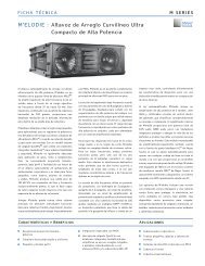
<strong>SB</strong>-2 DIMENSIONS<br />
9.56<br />
[243 mm]<br />
43.75<br />
[1111 mm]<br />
22.25<br />
[565 mm]<br />
<strong>SB</strong>-2 Dimensions<br />
46.47<br />
[1180 mm]<br />
31.22<br />
[793 mm]<br />
14.00<br />
[356 mm]<br />
<strong>SB</strong>-2 COMPLIANCE<br />
FCC Verified<br />
Class A<br />
25
<strong>Meyer</strong> <strong>Sound</strong> Laboratories Inc.<br />
2832 San Pablo Avenue<br />
Berkeley, CA 94702<br />
www.meyersound.com<br />
T: +1 510 486.1166<br />
F: +1 510 486.8356<br />
© 2013<br />
<strong>Meyer</strong> <strong>Sound</strong> Laboratories Inc.<br />
<strong>SB</strong>-2 <strong>Operating</strong> <strong>Instructions</strong>, PN 05.108.015.01 A