Syngas Mixture Composition Effects Upon Flashback and Blowout
Syngas Mixture Composition Effects Upon Flashback and Blowout
Syngas Mixture Composition Effects Upon Flashback and Blowout

Create successful ePaper yourself
Turn your PDF publications into a flip-book with our unique Google optimized e-Paper software.
were chosen based upon prior tests <strong>and</strong> visual observations of<br />
the flame shape <strong>and</strong> behavior.<br />
Figure 2: Premixer with swirler, centerbody, radial<br />
thermocouples, <strong>and</strong> centerbody thermocouple.<br />
In order to facilitate presentation of results, we represent<br />
the mixture composition of H 2 /CO/CH 4 by its color. Primary<br />
colors at the three vertices are used to represent each fuel<br />
constituent, where red, yellow, <strong>and</strong> blue denote H 2 , CO, <strong>and</strong><br />
CH 4 , respectively. This is illustrated in the figure below.<br />
Unfortunately, Figure 3 will be difficult to interpret if<br />
reproduced in grayscale.<br />
is purely a reference velocity, as the actual flow velocities may<br />
be different. The burned gas velocity simply equals this<br />
velocity multiplied by the theoretical temperature ratio across<br />
the flame. The velocity at the premixer exit, relevant for the<br />
flashback data, equals the unburned flow velocity multiplied<br />
by 18.<br />
It should be emphasized that applying a consistently<br />
uniform definition of flashback <strong>and</strong> blowoff is complicated by<br />
the fact that the manner in which the flame flashed back <strong>and</strong><br />
blew off varied with composition. Different flashback<br />
mechanisms were found for different fuel compositions. For<br />
low H 2 mixtures, the flame anchoring location moved<br />
gradually upstream (along the centerbody) with increased<br />
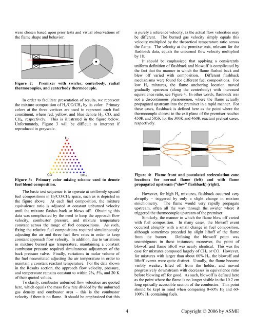
equivalence ratio, see Figure 4. In other words, flashback was<br />
not a discontinuous phenomenon, where the flame actually<br />
propagated upstream into the premixer in a rapid manner. For<br />
these cases, flashback is defined here as the point where the<br />
thermocouple closest to the exit plane of the premixer reaches<br />
450K <strong>and</strong> 505K for the 300K <strong>and</strong> 460K reactant preheat cases,<br />
respectively.<br />
Figure 3: Primary color mixing scheme used to denote<br />
fuel blend composition.<br />
The basic test sequence is to operate at uniformly spaced<br />
fuel compositions in H 2 /CO/CH 4 space, such as is depicted in<br />
the figure above. At each fuel composition, the mixture<br />
equivalence ratio is adjusted at constant unburned velocity<br />
until the mixture flashes back or blows off. Obtaining this<br />
data was complicated by the need to keep the approach flow<br />
velocity, combustor pressure, <strong>and</strong> mixture temperature<br />
constant across the range of fuel compositions. As such,<br />
fixing the relative fuel compositions required simultaneously<br />
adjusting the air <strong>and</strong> three fuel flow rates in order to keep<br />
constant approach flow velocity. In addition, due to variations<br />
in mixture burned gas temperature, maintaining a constant<br />
combustor pressure required simultaneous adjustment of the<br />
back pressure valve. Finally, variations in molar volume of<br />
the fuel necessitated adjusting the air temperature in order to<br />
maintain a constant reactant temperature. For the data shown<br />
in the Results section, the approach flow velocity, pressure,<br />
<strong>and</strong> temperature remains constant to within 2%, 5%, <strong>and</strong> 20 K<br />
of their quoted values.<br />
To clarify, combustor unburned flow velocities are quoted<br />
here, which equals the mass flow rate divided by the unburned<br />
gas density <strong>and</strong> combustor area – this is the combustor<br />
velocity if there is no flame. It should be emphasized that this<br />
Figure 4: Flame front <strong>and</strong> postulated recirculation zone<br />
locations for normal flame (left) <strong>and</strong> with flame<br />
propagated upstream (”slow” flashback) (right).<br />
However, for high H 2 mixtures, flashback occurred very<br />
abruptly – triggered by only a slight change in mixture<br />
stoichiometry. The flame would very rapidly propagate<br />
upstream, often all the way through the swirler where it<br />
triggered the thermocouple upstream of the premixer.<br />
Similarly, the manner in which the flame blew off varied<br />
with fuel composition. In many cases, the blowoff event<br />
occurred abruptly with a small change in fuel composition,<br />
although sometimes preceded by slight liftoff of the flame<br />
from the burner. Defining the blowoff point was<br />
unambiguous in these instances; moreover, the point of<br />
blowoff <strong>and</strong> flame liftoff was nearly identical. This was the<br />
case for mixtures composed largely of CH 4 or CO. However,<br />
for mixtures with larger than about 60% H 2 , the blowoff <strong>and</strong><br />
liftoff events were quite distinct. Usually, the flame became<br />
visibly weaker, lifted off from the holder, <strong>and</strong> moved<br />
progressively downstream with decreases in equivalence ratio<br />
before blowing off for good. As such, blowoff is defined here<br />
as the point where the flame is no longer visible in the 10.2 cm<br />
long optically accessible section of the combustor. This point<br />
should be kept in mind when comparing 0-60% H 2 <strong>and</strong> 60-<br />
100% H 2 containing fuels.<br />
4<br />
Copyright © 2006 by ASME