ATK-Motor-Catalog-2012
ATK-Motor-Catalog-2012
ATK-Motor-Catalog-2012

Create successful ePaper yourself
Turn your PDF publications into a flip-book with our unique Google optimized e-Paper software.
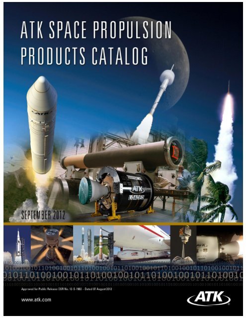
Approved for Public Release OSR No. 12-S-1902; Dated 07 August <strong>2012</strong>
Alliant Techsystems Inc.<br />
Alliant Techsystems, Inc.<br />
Tactical Propulsion and Controls<br />
Aerospace Group<br />
55 Thiokol Road 5000 South 8400 West<br />
Elkton, MD 21921 Magna, UT 84044<br />
Tel (410) 392-1000 Tel (801) 250-5911<br />
Fax (410) 392-1205<br />
Dear Customer:<br />
<strong>ATK</strong> would like to take this opportunity to provide you with the latest version of our Space<br />
Propulsion Products <strong>Catalog</strong> to help you address your future propulsion requirements. This catalog<br />
describes flight-proven motors and development motors in our product line.<br />
If the current production motors contained in this catalog do not address your specific needs, we<br />
have the capability to modify designs to meet your particular motor performance requirements. The<br />
practicality of tailoring motor performance has been demonstrated many times in derivatives of<br />
earlier design configurations (many examples exist in the STAR, Orion, and CASTOR ® series, for<br />
instance).<br />
<strong>ATK</strong> continues to invest in the development of new products and capabilities. Ongoing activities<br />
include new large boosters as well as extensive work with controllable solid-propulsion systems,<br />
which use proportional valves to control performance, and liquid and electric propulsion for small<br />
spacecraft.
TABLE OF CONTENTS<br />
<strong>ATK</strong> Space Propulsion Products <strong>Catalog</strong><br />
INTRODUCTION ................................................................................................................. 1<br />
LARGE MOTOR SUMMARY INFORMATION .................................................................... 5<br />
ORION MOTOR SERIES .................................................................................................. 11<br />
ORION 50S .......................................................................................................... 13<br />
ORION 50ST ........................................................................................................ 14<br />
ORION 50SG ....................................................................................................... 15<br />
ORION 50S XL ..................................................................................................... 16<br />
ORION 50S XLT .................................................................................................. 17<br />
ORION 50S XLG .................................................................................................. 18<br />
ORION 50 (50T) ................................................................................................... 19<br />
ORION 50 XL (50 XLT) ........................................................................................ 20<br />
ORION 38 ............................................................................................................ 21<br />
ORION 32 ............................................................................................................ 22<br />
CASTOR MOTOR SERIES ............................................................................................. 23<br />
CASTOR IVA ....................................................................................................... 24<br />
CASTOR IVA-XL .................................................................................................. 25<br />
CASTOR IVB ....................................................................................................... 26<br />
CASTOR 30 ......................................................................................................... 27<br />
CASTOR 30B ....................................................................................................... 28<br />
CASTOR 120 ....................................................................................................... 29<br />
LARGE CLASS STAGE (LCS) ......................................................................................... 31<br />
LCS I .................................................................................................................... 32<br />
LCS III .................................................................................................................. 33<br />
GEM MOTOR SERIES ..................................................................................................... 35<br />
GEM-40 (Ground-Ignited) .................................................................................... 36<br />
GEM-40 (Air-Ignited) ............................................................................................ 37<br />
GEM-40 VN .......................................................................................................... 38<br />
GEM-46 (Fixed, Ground-Ignited) ......................................................................... 39<br />
GEM-46 (Vectorable, Ground-Ignited) ................................................................. 40<br />
GEM-46 (Fixed, Air-Ignited) ................................................................................. 41<br />
GEM-60 (Vectorable) ........................................................................................... 42<br />
GEM-60 (Fixed) .................................................................................................... 43<br />
SOLID ROCKET MOTOR UPGRADE (SRMU) ................................................................ 45<br />
SRMU ................................................................................................................... 46<br />
REUSABLE SOLID ROCKET MOTOR (RSRM) .............................................................. 47<br />
RSRM ................................................................................................................... 48<br />
RSRM DERIVATIVES ....................................................................................................... 49<br />
1 SEGMENT RSRM ............................................................................................. 50<br />
1.5-SEGMENT RSRM.......................................................................................... 51<br />
2-SEGMENT RSRM............................................................................................. 52<br />
2.5 SEGMENT RSRM .......................................................................................... 53<br />
3-SEGMENT RSRM............................................................................................. 54<br />
4-SEGMENT RSRM............................................................................................. 55<br />
5-SEGMENT RSRM............................................................................................. 56<br />
STAR MOTOR SERIES ................................................................................................. 57<br />
STAR 3 TE-M-1082-1 ...................................................................................... 63<br />
STAR 3A TE-M-1089 ....................................................................................... 64<br />
STAR 4G TE-M-1061 ....................................................................................... 65<br />
STAR 5A TE-M-863-1 ...................................................................................... 66<br />
STAR 5C TE-M-344-15 .................................................................................... 67<br />
STAR 5CB TE-M-344-16 ................................................................................. 68<br />
STAR 5D TE-M-989-2 ...................................................................................... 69<br />
STAR 5F TE-M-1198 ....................................................................................... 70<br />
Approved for Public Release OSR No. 12-S-1902; Dated 07 August <strong>2012</strong><br />
i
<strong>ATK</strong> Space Propulsion Products <strong>Catalog</strong><br />
STAR 6B TE-M-790-1 ...................................................................................... 71<br />
STAR 8 TE-M-1076-1 ...................................................................................... 72<br />
STAR 9 TE-M-956-2 ........................................................................................ 73<br />
STAR 12GV TE-M-951 .................................................................................... 74<br />
STAR 13B TE-M-763 ....................................................................................... 75<br />
STAR 15G TE-M-1030-1 ................................................................................. 76<br />
STAR 17 TE-M-479 .......................................................................................... 77<br />
STAR 17A TE-M-521-5 .................................................................................... 78<br />
STAR 20 TE-M-640-1 ...................................................................................... 79<br />
STAR 24 TE-M-604 .......................................................................................... 80<br />
STAR 24C TE-M-604-4 .................................................................................... 81<br />
STAR 26 TE-M-442 .......................................................................................... 82<br />
STAR 26B TE-M-442-1 .................................................................................... 83<br />
STAR 26C TE-M-442-2 .................................................................................... 84<br />
STAR 27 TE-M-616 .......................................................................................... 85<br />
STAR 27H TE-M-1157 ...................................................................................... 86<br />
STAR 30 SERIES ............................................................................................................. 87<br />
STAR 30BP TE-M-700-20 ............................................................................... 88<br />
STAR 30C TE-M-700-18 .................................................................................. 89<br />
STAR 30C/BP TE-M-700-25 ............................................................................ 90<br />
STAR 30E TE-M-700-19 .................................................................................. 91<br />
STAR 31 AND 37 SERIES ................................................................................................ 93<br />
STAR 31 TE-M-762 .......................................................................................... 94<br />
STAR 37FM TE-M-783 .................................................................................... 95<br />
STAR 37FMV TE-M-1139 ................................................................................ 96<br />
STAR 37XFP TE-M-714-16/-17 ....................................................................... 97<br />
STAR 37GV TE-M-1007-1 ............................................................................... 98<br />
STAR 48 SERIES ............................................................................................................. 99<br />
STAR 48A TE-M-799-1 .................................................................................. 100<br />
STAR 48A TE-M-799 ..................................................................................... 101<br />
STAR 48B TE-M-711-17 ................................................................................ 102<br />
STAR 48B TE-M-711-18 ................................................................................ 103<br />
STAR 48BV TE-M-940-1 ............................................................................... 104<br />
STAR 63 SERIES ........................................................................................................... 105<br />
STAR 63D TE-M-936 ..................................................................................... 106<br />
STAR 63F TE-M-963-2 .................................................................................. 107<br />
STAR 75 SERIES ........................................................................................................... 109<br />
STAR 75 TE-M-775-1 .................................................................................... 110<br />
STAR 92 SERIES ........................................................................................................... 111<br />
STAR 92 ............................................................................................................. 112<br />
STAR STAGES ............................................................................................................... 113<br />
ELECTROMECHANICAL THRUST VECTOR ACTUATION SYSTEM .......................... 115<br />
ORION LAUNCH ABORT SYSTEM (LAS) ATTITUDE CONTROL MOTOR (ACM)...... 117<br />
ORION LAS ACM TE-M-1174-1 .................................................................... 118<br />
ADVANCED SOLID AXIAL STAGE (ASAS) MOTORS .............................................. 119<br />
ASAS 21-85V TE-M-1031-1 ........................................................................... 122<br />
ASAS 21-120 TE-M-1059-1 ............................................................................ 123<br />
ASAS 21-120V TE-M-909-1 ........................................................................... 124<br />
ORIOLE .............................................................................................................. 125<br />
ASAS 28-185/185V TE-T-1032 ...................................................................... 126<br />
ASAS 32-58V (RAVEN) TE-M-1106-1 ............................................................ 127<br />
LAUNCH STRUCTURES ................................................................................................ 129<br />
ATLAS V STRUCTURES ................................................................................... 130<br />
DELTA IV STRUCTURES ................................................................................. 131<br />
GEM ................................................................................................................... 132<br />
ORION ............................................................................................................... 133<br />
Approved for Public Release OSR No. 12-S-1902; Dated 07 August <strong>2012</strong><br />
ii
<strong>ATK</strong> Space Propulsion Products <strong>Catalog</strong><br />
PEGASUS ® ........................................................................................................ 134<br />
ORDNANCE PRODUCTS .............................................................................................. 135<br />
MODEL 2011 TE-O-958-1 .............................................................................. 142<br />
MODEL 2134B TE-O-734 .............................................................................. 143<br />
SCB INITIATOR TEM-I-902 ............................................................................ 144<br />
ESA TEM-O-1068-1 ....................................................................................... 145<br />
EOSA TE-O-1054-1 ........................................................................................ 146<br />
Approved for Public Release OSR No. 12-S-1902; Dated 07 August <strong>2012</strong><br />
iii
<strong>ATK</strong> Space Propulsion Products <strong>Catalog</strong><br />
This page intentionally left blank.<br />
Approved for Public Release OSR No. 12-S-1902; Dated 07 August <strong>2012</strong><br />
iv
ACRONYM LIST<br />
<strong>ATK</strong> Space Propulsion Products <strong>Catalog</strong><br />
ACS<br />
AKM<br />
ASAS<br />
BIT<br />
CSC<br />
CTPB<br />
EOSA<br />
EPDM<br />
ESA<br />
ETA<br />
ETR<br />
GBI<br />
Attitude control system — A thruster system used to maintain spacecraft/<br />
missile positioning and orientation. Also referred to as a reaction control<br />
system (RCS) in some applications<br />
Apogee kick motor — A motor used to circularize the orbit of a spacecraft,<br />
often to geosynchronous earth orbit (GEO)<br />
Advanced Solid Axial Stage — ASAS is used as a designation for a family of<br />
enhanced performance motors that generally incorporates common<br />
technologies such as high-strength graphite composite cases, high<br />
performance propellants, advanced ordnance, and/or thrust vector control<br />
nozzles with electromechanical actuation. These motors are identified by<br />
primary diameter, case length, and TVC content. For example, ASAS 21-<br />
120V is a 21-inch-diameter motor with a 120-inch case and TVC nozzle<br />
Built-in test — A feature of electronic devices that allows their operability to<br />
be confirmed via a signal provided in response to a test command or query<br />
Conical shaped charge — An ordnance product typically used as part of<br />
upper stage destruct systems to satisfy range safety requirements<br />
Carboxyl-terminated polybutadiene — A type of polymer used as a propellant<br />
binder<br />
Electro-optical safe and arm — A class of safe-and-arm device based on<br />
isolation of the unit and primary initiation functions using laser systems and<br />
fiber optics to reduce weight and eliminate sensitivity to electrostatic energy<br />
that results from the use of long wiring runs for ordnance systems typically<br />
used in launch vehicles<br />
Ethylene propylene diene monomer — A class of elastomeric rubber<br />
insulation materials typically used to insulate motor cases<br />
Electronic safe and arm — A class of safe-and-arm device based on the use<br />
of semiconductor bridge initiator technology. ESA designs provide<br />
capabilities for reporting health status of the ordnance system and<br />
incorporating specific safety and command and control protocols<br />
Explosive transfer assembly — ETAs are used as part of a space motor<br />
ignition train, generally to transfer the initiation signal from a safe-and-arm<br />
device to another ordnance component such as a through-bulkhead initiator<br />
(TBI). These may be further identified as an FETA = flexible ETA, or RETA =<br />
rigid ETA<br />
Eastern Test Range<br />
Ground-based interceptor<br />
Approved for Public Release OSR No. 12-S-1902; Dated 07 August <strong>2012</strong><br />
v
<strong>ATK</strong> Space Propulsion Products <strong>Catalog</strong><br />
GEM<br />
GEO<br />
GMD<br />
GPS<br />
GSE<br />
HEW<br />
HTPB<br />
IMP<br />
IRBM<br />
JPL<br />
LCS<br />
LEO<br />
MDA<br />
MER<br />
NSI<br />
PBAN<br />
PKM<br />
RAD<br />
RAVEN<br />
RCS<br />
Graphite epoxy motor — <strong>ATK</strong> developed GEM designs for the Delta II launch<br />
vehicle. Designed to take advantage of proven, off-the-shelf technologies,<br />
the GEM system provides increased performance and heavier lift capability<br />
Geosynchronous earth orbit — 22,600 miles out from the earth is an orbital<br />
location where satellites remain over a fixed point on the earth<br />
Ground-based Midcourse Defense<br />
Global positioning system — A satellite constellation providing precise<br />
navigation and location data for military and commercial users<br />
Ground support equipment — Equipment used to support motor integration<br />
with the spacecraft and/or launch vehicle and to provide associated final<br />
motor checks<br />
Head end web — A type of grain design in which the propellant completely<br />
covers and is generally bonded to the motor head end<br />
Hydroxyl terminated polybutadiene — A type of polymer used as a propellant<br />
binder<br />
Interplanetary monitoring platform<br />
Immediate-range ballistic missile<br />
Jet Propulsion Laboratory, Pasadena, CA<br />
Large class stage – A high-performance, high-reliability booster being<br />
developed by <strong>ATK</strong> with the support of the U.S. Air Force<br />
Low earth orbit — A position reached by the Space Shuttle and many launch<br />
systems prior to orbital adjustments that are typically made using perigee<br />
kick motor (PKM) and apogee kick motor (AKM) propulsion<br />
Missile Defense Agency<br />
Mars Exploration Rover — Designation for the 2003 to 2004 NASA missions<br />
to Mars that landed the Spirit and Opportunity rovers<br />
NASA standard initiator<br />
Polybutadiene acrylic acid acrylonitrile polymer — A binder formulation<br />
widely used on large rocket boosters such as the Titan III and Space Shuttle<br />
Perigee kick motor — A motor typically used to raise a satellite into elliptical<br />
orbit<br />
Rocket-assisted deceleration — Designation for motors used to decelerate<br />
payloads such as the Mars RAD motors<br />
RApid VEctoring Nozzle<br />
Reaction control system<br />
Approved for Public Release OSR No. 12-S-1902; Dated 07 August <strong>2012</strong><br />
vi
<strong>ATK</strong> Space Propulsion Products <strong>Catalog</strong><br />
RPM<br />
RSRM<br />
S&A<br />
SCB<br />
SRM<br />
SRMU<br />
SSB<br />
STS<br />
TBI<br />
TLI<br />
TCR<br />
TIRS<br />
TVA<br />
TVC<br />
UWARS<br />
WTR<br />
Revolutions per minute — Used to designate spin rates used to stabilize<br />
spacecraft. Note that the cited spin rates are the highest levels to which the<br />
design was tested or analyzed, not necessarily its maximum spin capability<br />
Reusable solid rocket motor — Designation used for the Space Shuttle<br />
boosters<br />
Safe and arm — Used to designate an electronic or electromechanical<br />
device that inhibits ordnance functions to provide enhanced safety<br />
Semiconductor bridge — The SCB chip is used in a line of initiators that<br />
provides fast and repeatable function times using low initiation energy<br />
Solid rocket motor<br />
Solid rocket motor upgrade — Originally developed for the U.S. Air Force<br />
and Lockheed Martin to increase the launch capability of the Titan IVB Space<br />
Launch Vehicle (retired)<br />
Solid strap-on booster<br />
Space Transportation System — The Space Shuttle<br />
Through bulkhead initiator — Part of a space motor ignition train<br />
Trans-Lunar Injection — Designation for a motor system used to inject a<br />
satellite into a lunar orbit. This specific designation applies to the STAR<br />
37FM-based TLI stage used for the Lunar Prospector spacecraft<br />
<strong>ATK</strong> line of resins and preimpregnated composite materials available in<br />
combination with a variety of fibers for industrial, commercial, and aerospace<br />
applications<br />
Transverse impulse rocket system — Designation for motors used to<br />
stabilize the lander during descent as part of the Mars Exploration Rover<br />
mission<br />
Thrust vector actuation — Refers to the system used to actuate a TVC<br />
nozzle<br />
Thrust vector control — Refers to a type of movable nozzle<br />
Universal water activated release system — A program that uses a qualified<br />
SCB initiator produced by Elkton<br />
Western Test Range<br />
Approved for Public Release OSR No. 12-S-1902; Dated 07 August <strong>2012</strong><br />
vii
<strong>ATK</strong> Space Propulsion Products <strong>Catalog</strong><br />
This page intentionally left blank.<br />
Approved for Public Release OSR No. 12-S-1902; Dated 07 August <strong>2012</strong><br />
viii
<strong>ATK</strong> Space Propulsion Products <strong>Catalog</strong><br />
Introduction<br />
<strong>ATK</strong>’s space propulsion and ordnance products outlined in this catalog reflect more than<br />
50 years of experience in providing high-performance and reliable propulsion for the<br />
aerospace industry. This catalog presents technical information on numerous product<br />
lines within the <strong>ATK</strong> Space Propulsion Product portfolio: Orion, CASTOR ® , CASTOR<br />
120 ® , LCS (large class stage), GEM (graphite epoxy motor), SRMU (solid rocket motor<br />
upgrade), the Space Shuttle RSRM (reusable solid rocket motor) and its derivative<br />
motors, the STAR series of space motors and integrated upper stages, ASAS<br />
(advanced solid axial stage), and space launch structures.<br />
RSRM Boosters<br />
Lift the Space Shuttle<br />
GEM and STAR Propulsion<br />
Power Delta II<br />
CASTOR and Orion<br />
<strong>Motor</strong>s Boost Taurus<br />
Solid rocket motor technology provides excellent reliability, tailorable ballistic<br />
performance, and low costs for many space, upper-stage, and missile defense<br />
applications. Introduction of high-strength composite materials has further enhanced<br />
performance for many classes of motors. In addition, <strong>ATK</strong> motors with thrust vector<br />
control nozzles and attitude control systems provide significant upgrades in solid<br />
propulsion system capabilities.<br />
STAR 48 <strong>Motor</strong> and<br />
Magellan Satellite Begin<br />
Journey to Venus<br />
Lunar Prospector<br />
(STAR 37<br />
Integrated Stage)<br />
CASTOR IVB Test<br />
________________________<br />
STAR and ASAS are trademarks of Alliant Techsystems. CASTOR and CASTOR 120 are registered<br />
trademarks of Alliant Techsystems.<br />
Copyright © <strong>2012</strong> by Alliant Techsystems Inc. All rights reserved.<br />
Approved for Public Release OSR No. 12-S-1902; Dated 07 August <strong>2012</strong><br />
1
<strong>ATK</strong> Space Propulsion Products <strong>Catalog</strong><br />
Sometimes existing designs must be modified, stretched, offloaded, or scaled up to<br />
achieve performance goals and/or to accommodate structural interfaces established for<br />
specific missions. As a result, <strong>ATK</strong> routinely modifies our products to meet evolving<br />
customer needs through detailed design, analysis, and testing of new propulsion systems<br />
that maintain the heritage of prior, flight-proven designs.<br />
Rapid Vectoring Nozzle (RAVEN)<br />
Demonstration <strong>Motor</strong><br />
ASAS 21-120 <strong>Motor</strong> Test<br />
Our ordnance products have also established excellent flight reliability records in both<br />
motor ignition and destruct system applications. Current electronic safe-and-arm<br />
technology can be applied by <strong>ATK</strong> to reduce ordnance weight and cost and to precisely<br />
control ordnance events for your propulsion systems.<br />
Addressable Bus Ordnance<br />
System<br />
ESA<br />
Conical Shaped Charge<br />
(destruct ordnance)<br />
We have also included an overview of <strong>ATK</strong>’s integrated stage capabilities. <strong>ATK</strong> has a<br />
broad range of capabilities, including simple stage hardware and stage/vehicle integration<br />
support, to more complex three-axis stabilized, inertially-guided vehicle designs. <strong>ATK</strong><br />
now offers fully autonomous single or multiple stage stacks and all of the required<br />
avionics hardware, flight software, and mission design and management services.<br />
In addition to hardware, <strong>ATK</strong> routinely provides a variety of support services, including<br />
engineering design trades, launch and integration support, field handling training, aging<br />
and surveillance, demilitarization, testing, and analysis. These services support mission<br />
assurance goals leading to successful flight. We also routinely provide shipping<br />
containers and ground support equipment for use with the motors. To accommodate new<br />
environments or structural interfaces, we can define and support delta-qualification of<br />
components and/or complete motor assemblies. <strong>ATK</strong> can also design skirts and<br />
Approved for Public Release OSR No. 12-S-1902; Dated 07 August <strong>2012</strong><br />
2
<strong>ATK</strong> Space Propulsion Products <strong>Catalog</strong><br />
interstages and provide heaters, thermal blankets, and flight termination ordnance to<br />
adapt our products to your needs.<br />
This catalog contains data sheets that summarize the principal design and performance<br />
characteristics of each motor or system. The information provided in the data sheets will<br />
permit initial evaluation of our current products in reference to your mission requirements.<br />
We encourage you to involve us in these evaluations and welcome the opportunity to<br />
provide optimal solutions for your mission needs.<br />
Inquiries regarding specific product lines should be directed to our business development<br />
representatives as listed below. In addition to the products noted in this catalog, <strong>ATK</strong> can<br />
provide reliable space structures, aerospace tanks, and hypersonic propulsion<br />
technology. For information about these and other <strong>ATK</strong> products, please visit our website<br />
at www.atk.com.<br />
Products Contact No. Contact E-mail Address<br />
STAR, ASAS, and CASTOR I and II<br />
<strong>Motor</strong>s; STAR Stages; Ordnance<br />
Orion, CASTOR, LCS, GEM, SRMU,<br />
and RSRM <strong>Motor</strong>s/derivatives<br />
Phone: (410) 392-1430<br />
Fax: (410) 392-1205<br />
Phone: (801) 251-5373<br />
Fax: (801) 251-5548<br />
Space Structures Phone: (801) 775-1262<br />
Fax: (801) 775-1207<br />
Tanks Phone: (323) 722-0222<br />
Fax: (323) 721-6002<br />
Hypersonic Propulsion Technology Phone: (631) 737-6100<br />
Fax: (631) 737-6121<br />
starmotors@atk.com<br />
businessdevelopment@atk.com<br />
composite.structures@atk.com<br />
psi.tank@atk.com<br />
GASL.Marketing@atk.com<br />
Approved for Public Release OSR No. 12-S-1902; Dated 07 August <strong>2012</strong><br />
3
<strong>ATK</strong> Space Propulsion Products <strong>Catalog</strong><br />
This page intentionally left blank.<br />
Approved for Public Release OSR No. 12-S-1902; Dated 07 August <strong>2012</strong><br />
4
<strong>ATK</strong> Space Propulsion Products <strong>Catalog</strong><br />
LARGE MOTOR SUMMARY<br />
INFORMATION<br />
ORION, CASTOR, LCS, GEM, AND RSRM<br />
MOTOR SERIES CAPABILITIES<br />
<strong>ATK</strong>’s large motor series (Orion, CASTOR, LCS, GEM, and RSRM families) span a<br />
significant range of size and boost capability, with motors ranging from approximately<br />
2,000 pounds up to 1.6 million pounds. The figure on the following page provides a<br />
graphic comparison of the relative sizes of the principal motors in these series.<br />
Tabular summaries of motor dimensions, weights, and performance data across these<br />
motor series are provided in Table 1, and a summary of test and flight experience is<br />
provided in Table 2. (NOTE: Similar summary data is provided under the STAR motor<br />
section for the STAR motor series.)<br />
Approved for Public Release OSR No. 12-S-1902; Dated 07 August <strong>2012</strong><br />
5
<strong>ATK</strong> Space Propulsion Products <strong>Catalog</strong><br />
1900<br />
1800<br />
1700<br />
1600<br />
1500<br />
1400<br />
1300<br />
1200<br />
1100<br />
1000<br />
900<br />
800<br />
700<br />
600<br />
500<br />
400<br />
300<br />
200<br />
100<br />
RSRMV<br />
RSRM<br />
SRMU<br />
GEM 60<br />
GEM 46<br />
ORION 50S XL<br />
GEM 40<br />
ORION 50ST<br />
ORION 32<br />
LCS I<br />
ORION 50XL<br />
CASTOR 120<br />
ORION 50<br />
ORION 38<br />
CASTOR 30<br />
1900<br />
1800<br />
1700<br />
1600<br />
1500<br />
1400<br />
1300<br />
1200<br />
1100<br />
1000<br />
900<br />
800<br />
700<br />
600<br />
500<br />
400<br />
300<br />
200<br />
100<br />
Inches<br />
<strong>ATK</strong> <strong>Motor</strong> Comparison<br />
Approved for Public Release OSR No. 12-S-1902; Dated 07 August <strong>2012</strong><br />
6
<strong>ATK</strong> Space Propulsion Products <strong>Catalog</strong><br />
<strong>Motor</strong><br />
Orion <strong>Motor</strong> Family<br />
Nozzle<br />
Diameter<br />
(inches)<br />
Table 1. Large <strong>Motor</strong> Summary<br />
Overall<br />
Length<br />
(inches)<br />
Propellant<br />
Weight (lbm)<br />
Total Weight<br />
(lbm)<br />
Mass Fraction<br />
Total Impulse<br />
(lbf-sec)<br />
Orion 32 Vectorable 32 121 4,280 4,721 0.91 1,186,000 41.0 Componentqualified<br />
Orion 38 Vectorable 38 52.6 1,698 1,924 0.88 491,140 66.8 Flight-proven<br />
Orion 50 Vectorable 50.2 103.2 6,669 7,395 0.90 1,949,000 75.1 Flight-proven<br />
Orion 50 XL Vectorable 50.2 120.9 8,631 9,494 0.91 2,521,900 71.0 Flight-proven<br />
Orion 50S Fixed 50.2 350.1 26,801 29,529 0.91 7,873,000 74.9 Flight-proven<br />
Orion 50ST Vectorable 50.2 335.4 26,801 29,103 0.92 7,676,500 74.2 Flight-proven<br />
Orion 50S XL Fixed 50.2 404.3 33,145 36,153 0.92 9,744,300 69.7 Flight-proven<br />
Orion 50S XLT Vectorable 50.2 390.8 33,145 35,763 0.93 9,472,400 69.0 Flight-proven<br />
Orion 50S XLG Vectorable 50.2 372.4 33,145 35,525 0.93 9,061,400 69.0 Flight-proven<br />
CASTOR <strong>Motor</strong> Family<br />
CASTOR IVA Fixed 40.1 363.4 22,286 25,737 0.87 5,967,840 55.2 Flight-proven<br />
CASTOR IVA-XL Fixed 40.1 457.0 28,906 33,031 0.88 8,140,170 58.0 Flight-proven<br />
CASTOR IVB Vectorable 40.1 353.7 21,990 25,441 0.86 5,880,600 63.6 Flight-proven<br />
CASTOR 30 Vectorable 92 138 28,108 30,565 0.92 8,236,000 153.4 Qualified at<br />
simulated<br />
altitude<br />
CASTOR 30B Vectorable 92 164 28,412 30,800 0.92 8,538,000 126.7 Qualified<br />
CASTOR 120 Vectorable 92 355 107,914 116,993 0.92 30,000,000 79.4 Flight-proven<br />
*Large Class Stage (LCS)<br />
*LCS I Vectorable 92.1 378.3 114,557 124,028 0.92 31,897,900 75.3 In Development<br />
*LCS III Vectorable 92.1 164.5 28,278 31,307 0.91 8,483,300 133.0 Qualified at<br />
simulated<br />
altitude<br />
Graphite Epoxy <strong>Motor</strong> (GEM) Family<br />
GEM-40<br />
Fixed<br />
(Air- Ignited)<br />
Burn<br />
Time<br />
(sec)<br />
Status<br />
40.4 449.1 25,940 28,883 0.90 7,351,000 63.3 Flight-proven<br />
GEM-40 VN Vectorable 40.4 425.1 25,940 28,886 0.90 6,959,000 64.6 Flight-proven<br />
GEM-46<br />
Fixed (Ground- 45.1 495.8 37,180 41,590 0.89 10,425,000 75.9 Flight-proven<br />
Ignited)<br />
GEM-46<br />
Vectorable<br />
(Ground-Ignited)<br />
45.1 491.5 37,180 42,196 0.88 10,400,000 76.9 Flight-proven<br />
GEM-46 Fixed (Air-Ignited) 45.1 508.6 37,180 42,039 0.88 10,803,000 75.9 Flight-proven<br />
GEM-60 Fixed 60 518 65,472 73,156 0.89 17,965,776 90.8 Flight-proven<br />
GEM-60 Vectorable 60 518 65,472 74,185 0.88 17,928,000 90.8 Flight-proven<br />
*Approved for public release by the U.S. Air Force, 14 June <strong>2012</strong><br />
Approved for Public Release OSR No. 12-S-1902; Dated 07 August <strong>2012</strong><br />
7
<strong>Motor</strong><br />
Nozzle<br />
Diameter<br />
(inches)<br />
Overall<br />
Length<br />
(inches)<br />
Propellant<br />
Weight (lbm)<br />
Total Weight<br />
(lbm)<br />
<strong>ATK</strong> Space Propulsion Products <strong>Catalog</strong><br />
Mass Fraction<br />
Total Impulse<br />
(lbf-sec)<br />
Solid Rocket <strong>Motor</strong> Upgrade (SRMU)<br />
SRMU Vectorable 126 1,349 695,427 776,038 0.89 195,476,128 135.7 Flight-proven<br />
Reusable Solid Rocket <strong>Motor</strong> (RSRM) and Derivatives<br />
RSRM Vectorable 146.1 1,513.5 1,106,059 1,255,334 0.88 297,001,731 122.2 Flight-proven<br />
1-Segment Commercial Vectorable 146.1 499.6 336,231 404,601 0.83 92,978,688 115.8 Design<br />
1.5-Segment Commercial Vectorable 146.1 697 476,496 558,993 0.85 132,700,522 117 Design<br />
2-Segment Commercial Vectorable 146.1 860 619,003 715,659 0.86 170,800,000 114.1 Design<br />
2.5-Segment Commercial Vectorable 146.1 1,037 758,990 867,215 0.87 209,304,469 113.2 Design<br />
3-Segment Commercial Vectorable 146.1 1,156.2 843,286 981,686 0.86 223,000,000 133.7 Design<br />
4-Segment Commercial Vectorable 146.1 1,476.3 1,114,155 1,278,078 0.87 298,000,000 132.8 Design<br />
RSRM V<br />
(5-Segment)<br />
Vectorable 146.1 1,864.7 1,427,807 1,616,123 0.88 381,367,646 131.9 Completing<br />
Development<br />
Burn<br />
Time<br />
(sec)<br />
Status<br />
Table 2. Large <strong>Motor</strong> Test and Flight History (as of 13 June <strong>2012</strong>)<br />
<strong>Motor</strong><br />
Applications/Uses<br />
Number of Static<br />
Fire Tests<br />
Number of <strong>Motor</strong>s<br />
Flown<br />
TVC<br />
Production Status<br />
Orion 32 Technology Demonstration 2 (HCDM, MCRT) 0 Yes Development<br />
Orion 32-5 Technology Demonstration 1 0 Yes Development<br />
Orion 32-7 Technology Demonstration 1 0 Yes Development<br />
Orion 38<br />
Pegasus/Taurus/Pegasus XL/ Taurus<br />
XL/Minotaur I/Minotaur IV/GMD OBV<br />
1 71 Optional Production<br />
Orion 38HP Technology Demonstration 1 0 Yes Development<br />
Orion 50 Pegasus Std 1 10 Optional Out of Production<br />
Orion 50T Taurus Std 0 6 Optional Out of Production<br />
Orion 50 XL Pegasus XL/Minotaur/OBV 1 51 Optional Production<br />
Orion 50 XLT Taurus XL/IRBM Target 0 3 Optional Production<br />
Orion 50S Pegasus Std/Hyper-X 1 13 No Out of Production<br />
Orion 50ST Taurus Std 1 6 Optional Out of Production<br />
Orion 50SG 0 0 Optional Out of Production<br />
Orion 50S XL Pegasus XL 1 31 No Production<br />
Orion 50S XLG GMD OBV/ALV 5 11 Optional Production<br />
Orion 50S XLT Taurus XL/IRBM Target 0 3 Optional Production<br />
CASTOR IVA Delta II/Atlas 2AS 7 313 No Out of Production<br />
CASTOR IVB Maxus/Targets 4 32 Yes Out of Production<br />
CASTOR IVA-XL HII-A 4 34 No Out of Production<br />
Approved for Public Release OSR No. 12-S-1902; Dated 07 August <strong>2012</strong><br />
8
<strong>ATK</strong> Space Propulsion Products <strong>Catalog</strong><br />
<strong>Motor</strong><br />
Applications/Uses<br />
Number of Static<br />
Fire Tests<br />
Number of <strong>Motor</strong>s<br />
Flown<br />
TVC<br />
Production Status<br />
CASTOR 30 Antares/Athena Ic/Athena IIc 1 0 Yes Production<br />
CASTOR 30B Antares 0 0 Yes Production<br />
CASTOR 120 Athena Ic/Athena IIc/ Taurus/Taurus XL 2 16 Yes Production<br />
LCS I Conventional Strike/Family of <strong>Motor</strong>s 0 0 Yes In Development<br />
LCS III Conventional Strike/Family of <strong>Motor</strong>s 1 0 Yes In Development<br />
GEM 40 Delta 2 13 984 No Production<br />
GEM 40VN GMD BV+ 3 3 Yes Out of Production<br />
GEM 46 Delta 2 Heavy/Delta 3 3 81 Fixed/TVC Out of Production<br />
GEM 60 Delta 4 13 26 Fixed/TVC Production<br />
SRMU Titan IVB 6 34 Yes Out of Production<br />
RSRM Space Shuttle 28<br />
220 Yes Out of Production<br />
(+5-seg ETM-3)<br />
1-Seg. RSRM 0 0 Yes Concept<br />
1.5-Seg. RSRM 0 0 Yes Concept<br />
2-Seg. RSRM 0 0 Yes Concept<br />
2.5-Seg. RSRM 0 0 Yes Concept<br />
3-Seg. RSRM 0 0 Yes Design<br />
4-Seg. RSRM 0 0 Yes Design<br />
RSRM V<br />
(5-Seg.)<br />
Space Launch System (SLS) / formerly Ares I<br />
First Stage<br />
3 0<br />
(+Ares I-X, 4-seg)<br />
Yes<br />
Completing Development<br />
Reliability/Success Rate: Demonstrated success rate of 99.76% in flight and static tests. One static test failure and four flight failures in 2,055<br />
tests and flights (two TVC related). Two of the flight failures were subsequently attributed to damage resulting from handling and post-delivery<br />
flight processing.<br />
Approved for Public Release OSR No. 12-S-1902; Dated 07 August <strong>2012</strong><br />
9
<strong>ATK</strong> Space Propulsion Products <strong>Catalog</strong><br />
This page intentionally left blank.<br />
Approved for Public Release OSR No. 12-S-1902; Dated 07 August <strong>2012</strong><br />
10
<strong>ATK</strong> Space Propulsion Products <strong>Catalog</strong><br />
ORION MOTOR SERIES<br />
AFFORDABLE, LOW-RISK FLEXIBLE CAPABILITIES<br />
Orion Series<br />
The Orion family of motors began with three stages originally designed for use in a joint<br />
venture with Orbital Sciences Corp. for the Pegasus® launch vehicle. Modifications to the<br />
original three Orion motors, first for extended length (XL) versions and subsequently for<br />
skirt, nozzle, and other smaller differences, have accommodated additional applications<br />
and enhanced performance capabilities. Vehicle applications successfully flown using<br />
Orion motors include Pegasus®, Taurus®, Pegasus® XL, Minotaur®, Hyper-X, Taurus<br />
Lite and Taurus® XL launch vehicles, and the Ground-based Midcourse Defense (GMD)<br />
ground-based interceptor (GBI). New applications continue to evolve, such as target<br />
vehicle configurations for Missile Defense Agency (MDA).<br />
The multiple configurations and applications currently existing demonstrate that these<br />
flight-proven motors are readily adaptable to a wide range of launch scenarios (e.g.,<br />
ground-start, air-start, silo-launched, etc.) and missions. <strong>ATK</strong> has also demonstrated<br />
support for their deployment and use at a wide range of launch sites and field locations,<br />
including multiple non-Continental United States launch sites. Further, it should be noted<br />
that much of the adaptation has been accomplished with only relatively minor changes<br />
(skirt thicknesses and hole patterns, nozzle length, etc.), with little or no changes to the<br />
basic motor.<br />
The current major vehicle applications and variants for Orion motors are shown in the<br />
table below. The motor identification key provides a further explanation for nomenclature<br />
designations in the Orion motor series.<br />
Approved for Public Release OSR No. 12-S-1902; Dated 07 August <strong>2012</strong><br />
11
Flight-Proven Orion <strong>Motor</strong> Configurations<br />
Orion <strong>Motor</strong><br />
First Stage Second Stage Third Stage Fourth Stage<br />
<strong>ATK</strong> Space Propulsion Products <strong>Catalog</strong><br />
50S 50 38 Pegasus<br />
Vehicle<br />
Application<br />
50S XL 50 XL 38 Pegasus XL<br />
50ST 50T 38 Taurus<br />
50S XL 50 XLT 38 Taurus XL<br />
50S XLG 50 XL 38 Taurus Lite<br />
50S<br />
50 XL 38 Minotaur<br />
Hyper-X<br />
50S XLG 50 XLT 38 GMD GBI<br />
50S XL 50 XLT IRBM target*<br />
* initial flight set in production<br />
<strong>Motor</strong> Identification Key<br />
Example Orion 50 S XL G T<br />
SRM class<br />
SRM diameter (in)<br />
Stretch<br />
• With “S” denotes Stage 1<br />
• Without “S” denotes Stage 2<br />
XL or Std motor length<br />
• “XL” denotes extra length (otherwise standard length)<br />
Nozzle configuration<br />
• “G” denotes ground-launched (truncated exit cone)<br />
Thicker skirt<br />
• “T” denotes thicker skirt (increased structural capacity)<br />
Approved for Public Release OSR No. 12-S-1902; Dated 07 August <strong>2012</strong><br />
12
ORION 50S<br />
AIR-IGNITED, FIXED NOZZLE<br />
The Orion 50S was developed as a low-cost, high-performance first<br />
stage for the Pegasus launch vehicle. The 50S configuration,<br />
shown above incorporating a saddle attachment, has a fixed nozzle<br />
and is air ignited after a 5-second freefall drop from approximately<br />
40,000 ft. The Orion 50S has launched Pegasus satellite missions<br />
into successful orbit, some of which were Pegsat, Microsat, SCD-1<br />
(Brazil’s first data collection satellite), Alexis, and Space Test<br />
Experiment Platform (STEP)-2. This motor, with some additional<br />
modifications, has also been used as a booster in Hyper-X flights to<br />
support scramjet flight-testing.<br />
MOTOR DIMENSIONS<br />
<strong>Motor</strong> diameter, in. ............................................... 50.2<br />
Overall motor length (including nozzle), in. ....... 350.1<br />
Nozzle exit cone diameter, in............................... 56.0<br />
MOTOR PERFORMANCE (60°F NOMINAL,<br />
VACUUM)<br />
Burn time to 30 psia, sec ..................................... 74.9<br />
Maximum thrust, lbf ....................................... 126,641<br />
Effective specific impulse, lbf-sec/lbm… ....... 292.25*<br />
Total impulse, lbf-sec ................................ 7,873,000*<br />
Burn time average thrust, lbf.......................... 105,097<br />
* Includes 137 lbm of expended inerts<br />
WEIGHTS, LBM<br />
Total motor ....................................................... 29,529<br />
Propellant ........................................................ 26,801<br />
Burnout .............................................................. 2,533<br />
PROPELLANT DESIGNATION<br />
...................... QDL-1, HTPB polymer, 19% aluminum<br />
HAZARDS CLASSIFICATION… ...................1.3<br />
RACEWAY ........................................... Optional<br />
ORDNANCE ......................................... Optional<br />
TVA .............................................................. No<br />
TEMPERATURE LIMITS<br />
Operation ................................................. +36°-100°F<br />
Storage…. ................................................ +30°-100°F<br />
PRODUCTION STATUS<br />
............................... Flight proven, inactive production<br />
** Pegasus standard first stage<br />
Approved for Public Release<br />
OSR No. 12-S-1902;<br />
Dated 07 August <strong>2012</strong><br />
13
ORION 50ST<br />
AIR-IGNITED, VECTORABLE NOZZLE<br />
Another version, Orion 50ST, incorporates a ± 5-degree moveable<br />
nozzle for the air-ignited, Taurus Stage 1. This version has flown<br />
on all six Taurus missions (both Air Force and commercial<br />
versions), such as the Multi-Spectral Thermal Imager (MTI),<br />
Orbview-4, Korea Multi-Purpose Satellite (KOMPSAT), etc.<br />
MOTOR DIMENSIONS<br />
<strong>Motor</strong> diameter, in. ............................................... 50.2<br />
Overall motor length (including nozzle), in. ....... 335.4<br />
Nozzle exit cone diameter, in............................... 47.6<br />
MOTOR PERFORMANCE (60°F NOMINAL,<br />
VACUUM)<br />
Burn time, sec ...................................................... 74.2<br />
Maximum thrust, lbf ....................................... 122,099<br />
Effective specific impulse, lbf-sec/lbm… ....... 284.97*<br />
Total impulse, lbf-sec ................................ 7,676,500*<br />
Burn time average thrust, lbf.......................... 103,356<br />
* Includes 137 lbm of expended inerts<br />
WEIGHTS, LBM<br />
Total motor ....................................................... 29,103<br />
Propellant ........................................................ 26,801<br />
Burnout .............................................................. 2,165<br />
PROPELLANT DESIGNATION<br />
...................... QDL-1, HTPB polymer, 19% aluminum<br />
HAZARDS CLASSIFICATION… ...................1.3<br />
RACEWAY ........................................... Optional<br />
ORDNANCE ........................................ Optional<br />
TVA ..................................................... Optional<br />
TEMPERATURE LIMITS<br />
Operation ................................................. +36°-100°F<br />
Storage .................................................... +30°-100°F<br />
PRODUCTION STATUS<br />
.............................. Flight-proven, inactive production<br />
** Taurus standard first stage<br />
Approved for Public Release<br />
OSR No. 12-S-1902;<br />
Dated 07 August <strong>2012</strong><br />
14
ORION 50SG<br />
GROUND-IGNITED, VECTORABLE NOZZLE<br />
Another version, Orion 50SG, incorporates a ± 3-degree moveable<br />
nozzle for a ground-ignited Stage 1 configuration. This version is<br />
similar to what has flown on the standard Taurus missions, but with<br />
a shorter nozzle.<br />
MOTOR DIMENSIONS<br />
<strong>Motor</strong> diameter, in. ............................................... 50.2<br />
Overall motor length (including nozzle), in. ....... 318.3<br />
Nozzle exit cone diameter, in............................... 36.0<br />
MOTOR PERFORMANCE (60°F NOMINAL,<br />
VACUUM)<br />
Burn time, sec ...................................................... 74.2<br />
Maximum thrust, lbf ....................................... 117,358<br />
Effective specific impulse, lbf-sec/lbm… ......... 273.7*<br />
Total impulse, lbf-sec ................................ 7,372,900*<br />
Burn time average thrust, lbf............................ 99,268<br />
* Includes 137 lbm of expended inerts<br />
WEIGHTS, LBM<br />
Total motor ....................................................... 28,865<br />
Propellant ........................................................ 26,801<br />
Burnout .............................................................. 1,930<br />
PROPELLANT DESIGNATION<br />
...................... QDL-1, HTPB polymer, 19% aluminum<br />
HAZARDS CLASSIFICATION… ...................1.3<br />
RACEWAY ........................................... Optional<br />
ORDNANCE ........................................ Optional<br />
TVA ..................................................... Optional<br />
TEMPERATURE LIMITS<br />
Operation ................................................. +36°-100°F<br />
Storage .................................................... +30°-100°F<br />
PRODUCTION STATUS<br />
..................................... Qualified, inactive production<br />
Approved for Public Release<br />
OSR No. 12-S-1902;<br />
Dated 07 August <strong>2012</strong><br />
15
ORION 50S XL<br />
AIR-IGNITED, FIXED NOZZLE<br />
A performance upgrade of the Orion 50S, the Orion 50S XL, is 55.4<br />
inches longer and contains 6,500 lbm more propellant. To date, this<br />
fixed-nozzle XL version has performed successfully on 30 Pegasus<br />
XL launch vehicle missions, such as the Solar Radiation and<br />
Climate Experiment (SORCE), Fast Auroral Snapshot (FAST), High<br />
Energy Solar Spectroscopic Imager (HESSI), Orbview-3, and<br />
Transition Region and Coronal Explorer (TRACE).<br />
MOTOR DIMENSIONS<br />
<strong>Motor</strong> diameter, in. ............................................... 50.2<br />
Overall motor length (including nozzle), in. ....... 404.3<br />
Nozzle exit cone diameter, in............................... 56.0<br />
MOTOR PERFORMANCE (60°F NOMINAL,<br />
VACUUM)<br />
Burn time to 30 psia, sec ..................................... 69.7<br />
Maximum thrust, lbf ....................................... 160,404<br />
Effective specific impulse, lbf-sec/lbm… ....... 292.78*<br />
Total impulse, lbf-sec ................................ 9,744,300*<br />
Burn time average thrust, lbf.......................... 139,726<br />
* Includes 137 lbm of expended inerts<br />
WEIGHTS, LBM<br />
Total motor ....................................................... 36,153<br />
Propellant ........................................................ 33,145<br />
Burnout .............................................................. 2,837<br />
PROPELLANT DESIGNATION<br />
...................... QDL-1, HTPB polymer, 19% aluminum<br />
HAZARDS CLASSIFICATION… ...................1.3<br />
RACEWAY .......................................... Optional<br />
ORDNANCE ........................................ Optional<br />
TVA .............................................................. No<br />
TEMPERATURE LIMITS<br />
Operation ................................................. +36°-100°F<br />
Storage .................................................... +30°-100°F<br />
PRODUCTION STATUS<br />
............................................ Flight-proven, production<br />
**Pegasus XL first stage<br />
Approved for Public Release<br />
OSR No. 12-S-1902;<br />
Dated 07 August <strong>2012</strong><br />
16
ORION 50S XLT<br />
AIR-IGNITED, VECTORABLE NOZZLE<br />
Vectorable nozzle configurations of the Orion 50S XL have also<br />
been added to support versatility and new applications. One such<br />
configuration, Orion 50S XLT, has been used as a second-stage<br />
motor on the enhanced Taurus XL vehicle, which first launched in<br />
May 2004. This version incorporates a ± 5-degree vectorable<br />
nozzle and thicker skirts.<br />
MOTOR DIMENSIONS<br />
<strong>Motor</strong> diameter, in. ............................................... 50.2<br />
Overall motor length (including nozzle), in. ....... 390.8<br />
Nozzle exit cone diameter, in............................... 47.6<br />
MOTOR PERFORMANCE (60°F NOMINAL,<br />
VACUUM)<br />
Burn time to 30 psia, sec ..................................... 69.0<br />
Maximum thrust, lbf… .................................... 156,823<br />
Effective specific impulse, lbf-sec/lbm ........... 284.61*<br />
Total impulse, lbf-sec ................................ 9,472,400*<br />
Burn time average thrust, lbf.......................... 137,192<br />
* Includes 137 lbm of expended inerts<br />
WEIGHTS, LBM<br />
Total motor ....................................................... 35,763<br />
Propellant ........................................................ 33,145<br />
Burnout .............................................................. 2,472<br />
PROPELLANT DESIGNATION<br />
...................... QDL-1, HTPB polymer, 19% aluminum<br />
HAZARDS CLASSIFICATION… ...................1.3<br />
RACEWAY ........................................... Optional<br />
ORDNANCE ........................................ Optional<br />
TVA ..................................................... Optional<br />
TEMPERATURE LIMITS<br />
Operation ................................................. +36°-100°F<br />
Storage .................................................... +30°-100°F<br />
PRODUCTION STATUS<br />
............................................ Flight-proven, production<br />
**Taurus XL first stage<br />
Approved for Public Release<br />
OSR No. 12-S-1902;<br />
Dated 07 August <strong>2012</strong><br />
17
ORION 50S XLG<br />
GROUND-IGNITED, VECTORABLE NOZZLE<br />
A ground ignited, vectorable nozzle configuration with ± 5-degree<br />
vector capability has also been developed, designated Orion 50S<br />
XLG. This motor was first flown on the Taurus Lite vehicle,<br />
February 2003, as the ground-ignited first stage.<br />
MOTOR DIMENSIONS<br />
<strong>Motor</strong> diameter, in. ............................................... 50.2<br />
Overall motor length (including nozzle), in. ....... 372.4<br />
Nozzle exit cone diameter, in............................... 36.0<br />
MOTOR PERFORMANCE (60°F NOMINAL,<br />
VACUUM)<br />
Burn time to 30 psia, sec ..................................... 69.0<br />
Maximum thrust, lbf… .................................... 150,010<br />
Effective specific impulse, lbf-sec/lbm ........... 272.26*<br />
Total impulse, lbf-sec ................................ 9,061,400*<br />
Burn time average thrust, lbf.......................... 131,200<br />
* Includes 137 lbm of expended inerts<br />
WEIGHTS, LBM<br />
Total motor ....................................................... 35,525<br />
Propellant ........................................................ 33,145<br />
Burnout .............................................................. 2,237<br />
PROPELLANT DESIGNATION<br />
...................... QDL-1, HTPB polymer, 19% aluminum<br />
HAZARDS CLASSIFICATION… ...................1.3<br />
RACEWAY ........................................... Optional<br />
ORDNANCE ......................................... Optional<br />
TVA ..................................................... Optional<br />
TEMPERATURE LIMITS<br />
Operation ................................................. +36°-100°F<br />
Storage .................................................... +30°-100°F<br />
PRODUCTION STATUS<br />
............................................ Flight-proven, production<br />
**Taurus Lite and GMD first stage<br />
Approved for Public Release<br />
OSR No. 12-S-1902;<br />
Dated 07 August <strong>2012</strong><br />
18
ORION 50 (50T)<br />
AIR-IGNITED, VECTORABLE NOZZLE<br />
The Orion 50 was developed as a low-cost, high-performance<br />
second stage for the Pegasus launch vehicle. It incorporates a<br />
moveable nozzle with ± 5-degree vector capability. The motor was<br />
designed for upper stage applications but can readily<br />
accommodate lower expansion ratios, such as for ground-launch<br />
application, using a truncated nozzle. The Orion 50 has propelled<br />
10 satellite missions into successful orbit, including: Pegsat,<br />
Microsat, SCD-1 (Brazil’s first data collection satellite), Alexis, and<br />
Space Test Experiment Platform (STEP)-2. A nearly identical<br />
version with slightly enhanced skirts, the Orion 50T, has also flown<br />
successfully on six Taurus launch vehicle flights.<br />
MOTOR DIMENSIONS<br />
<strong>Motor</strong> diameter, in. ............................................... 50.2<br />
Overall motor length (including nozzle), in. ....... 103.2<br />
Nozzle exit cone diameter, in............................... 33.9<br />
MOTOR PERFORMANCE (60°F NOMINAL,<br />
VACUUM)<br />
Burn time to 30 psia, sec ..................................... 75.1<br />
Maximum thrust, lbf…. ..................................... 29,554<br />
Effective specific impulse, lbf-sec/lbm ........... 290.23*<br />
Total impulse, lbf-sec ................................ 1,949,000*<br />
Burn time average thrust, lbf............................ 25,939<br />
* Includes 46.4 lbm of expended inerts<br />
WEIGHTS, LBM<br />
Total motor ......................................................... 7,395<br />
Propellant .......................................................... 6,669<br />
Burnout ................................................................. 670<br />
PROPELLANT DESIGNATION<br />
...................... QDL-1, HTPB polymer, 19% aluminum<br />
HAZARDS CLASSIFICATION… ...................1.3<br />
RACEWAY .................................................. Yes<br />
ORDNANCE ......................................... Optional<br />
TVA ...................................................... Optional<br />
TEMPERATURE LIMITS<br />
Operation ................................................. +36°-100°F<br />
Storage .................................................... +30°-100°F<br />
PRODUCTION STATUS<br />
.............................. Flight-proven, inactive production<br />
**Pegasus and Taurus standard second stage<br />
Approved for Public Release<br />
OSR No. 12-S-1902;<br />
Dated 07 August <strong>2012</strong><br />
19
ORION 50 XL (50 XLT)<br />
AIR-IGNITED, VECTORABLE NOZZLE<br />
A flight-proven, extended-length version of the initial Orion 50 is<br />
also available. The Orion 50 XL is 18 inches longer and contains<br />
almost 2,000 lbm more propellant than the Orion 50. It flew on the<br />
1995 Space Test Experiment Platform (STEP)-3 mission as the<br />
second stage of the Pegasus XL. It has also flown as the thirdstage<br />
motor for the Air Force’s Minotaur launch vehicle as part of<br />
the Orbital/Suborbital Program and as the second stage on the<br />
Taurus Lite vehicle. In addition, a nearly identical version with<br />
heavier skirts, the Orion 50 XLT, launched in May 2004 as a<br />
second-stage motor on the enhanced Taurus XL launch vehicle.<br />
MOTOR DIMENSIONS<br />
<strong>Motor</strong> diameter, in. ............................................... 50.2<br />
Overall motor length (including nozzle), in. ....... 120.9<br />
Nozzle exit cone diameter, in............................... 33.9<br />
MOTOR PERFORMANCE (60°F NOMINAL,<br />
VACUUM)<br />
Burn time to 30 psia, sec ..................................... 71.0<br />
Maximum thrust, lbf… ...................................... 43,713<br />
Effective specific impulse, lbf-sec/lbm ........... 290.65*<br />
Total impulse, lbf-sec ................................ 2,521,900*<br />
Burn time average thrust, lbf............................ 35,511<br />
* Includes 46.4 lbm of expended inerts<br />
WEIGHTS, LBM<br />
Total motor ......................................................... 9,494<br />
Propellant .......................................................... 8,631<br />
Burnout ................................................................. 808<br />
PROPELLANT DESIGNATION<br />
...................... QDL-1, HTPB polymer, 19% aluminum<br />
HAZARDS CLASSIFICATION… ...................1.3<br />
RACEWAY .................................................. Yes<br />
ORDNANCE ........................................ Optional<br />
TVA ..................................................... Optional<br />
TEMPERATURE LIMITS<br />
Operation ................................................. +36°-100°F<br />
Storage .................................................... +30°-100°F<br />
PRODUCTION STATUS<br />
............................................ Flight-proven, production<br />
**Pegasus XL second stage, Minotaur third stage<br />
Approved for Public Release<br />
OSR No. 12-S-1902;<br />
Dated 07 August <strong>2012</strong><br />
20
ORION 38<br />
AIR-IGNITED, VECTORABLE NOZZLE<br />
UPPER-STAGE BOOSTER<br />
The Orion 38 was developed as a low-cost, high-performance third<br />
stage for the Pegasus launch vehicle and incorporates a ± 5-<br />
degree vectorable nozzle. It also functions as the standard thirdstage<br />
motor for other launch vehicles such as the Pegasus XL;<br />
Taurus, Taurus XL, and Taurus Lite launch vehicles; and as the<br />
fourth stage of the Air Force’s Minotaur vehicle. This motor has<br />
performed successfully in more than 70 flights over two decades of<br />
use.<br />
MOTOR DIMENSIONS<br />
<strong>Motor</strong> diameter, in. ............................................... 38.0<br />
Overall motor length (including nozzle), in. ......... 52.6<br />
Nozzle exit cone diameter, in............................... 20.7<br />
MOTOR PERFORMANCE (60°F NOMINAL,<br />
VACUUM)<br />
Burn time to 30 psia, sec ..................................... 66.8<br />
Maximum thrust, lbf… ........................................ 8,303<br />
Effective specific impulse, lbf-sec/lbm ........... 286.97*<br />
Total impulse, lbf-sec ................................... 491,140*<br />
Burn time average thrust, lbf.............................. 7,352<br />
* Includes 14.6 lbm of expended inerts<br />
WEIGHTS, LBM<br />
Total motor ......................................................... 1,924<br />
Propellant .......................................................... 1,698<br />
Burnout ................................................................. 206<br />
PROPELLANT DESIGNATION<br />
...................... QDL-1, HTPB polymer, 19% aluminum<br />
HAZARDS CLASSIFICATION… ...................1.3<br />
RACEWAY .................................................... No<br />
ORDNANCE ........................................ Optional<br />
TVA ..................................................... Optional<br />
TEMPERATURE LIMITS<br />
Operation ................................................. +36°-100°F<br />
Storage .................................................... +30°-100°F<br />
PRODUCTION STATUS<br />
............................................ Flight-proven, production<br />
Approved for Public Release<br />
OSR No. 12-S-1902;<br />
Dated 07 August <strong>2012</strong><br />
21
Vacuum Thrust (lbf)<br />
ORION 32<br />
VECTORABLE NOZZLE IN-LINE BOOSTER<br />
The Orion 32 is a low-cost, high-performance derivative of an<br />
existing upper-stage motor. This development motor is 121 inches<br />
long and nominally designed as a second-stage motor. A longer<br />
version (up to 255 inches) for potential first stage application and a<br />
reduced length version (down to 70 inches) are also in design<br />
evaluation. This motor configuration has not flown; however, all<br />
components, except skirts, are flight-proven.<br />
MOTOR DIMENSIONS<br />
<strong>Motor</strong> diameter, in. .................................................. 32<br />
Overall motor length (including nozzle), in. .......... 121<br />
MOTOR PERFORMANCE (70°F NOMINAL,<br />
VACUUM)<br />
Burn time, sec ......................................................... 41<br />
Average chamber pressure, psia .......................... 660<br />
Total impulse, lbf-sec .................................. 1,186,000<br />
Burn time average thrust, lbf............................ 28,800<br />
NOZZLE<br />
Housing material ......................................... Aluminum<br />
Exit diameter, in. .................................................. 24.9<br />
Expansion ratio, average ........................................ 23<br />
WEIGHTS, LBM<br />
Total loaded ....................................................... 4,721<br />
Propellant .......................................................... 4,280<br />
Burnout ................................................................. 418<br />
PROPELLANT DESIGNATION<br />
...................... QDL-2, HTPB polymer, 20% aluminum<br />
RACEWAY .......................................... Optional<br />
ORDNANCE ........................................ Optional<br />
TVA ..................................................... Optional<br />
TEMPERATURE LIMITS<br />
Operation ................................................. +20°-100°F<br />
Storage .................................................... +20°-100°F<br />
PRODUCTION STATUS ......................... In design<br />
35,000<br />
Thrust vs Time Profile<br />
30,000<br />
25,000<br />
20,000<br />
15,000<br />
10,000<br />
5,000<br />
0<br />
0 10 20 30 40<br />
Burn Time (Sec)<br />
Approved for Public Release<br />
OSR No. 12-S-1902;<br />
Dated 07 August <strong>2012</strong><br />
22
<strong>ATK</strong> Space Propulsion Products <strong>Catalog</strong><br />
CASTOR MOTOR SERIES<br />
LOW-COST, HIGH-RELIABILITY BOOSTERS<br />
The CASTOR motor family was originally developed in the mid-to-late 1950s to support<br />
the NASA Scout and Little Joe vehicles. In 1969, the CASTOR IV was developed to<br />
provide first stage propulsion for the Athena H and was later adapted as a strap-on<br />
booster for Delta II. The CASTOR I-IV family has a combined total of over 1,900 flights<br />
and a demonstrated reliability of 99.95%. Since then, newer derivatives including the<br />
CASTOR IVA, IVA-XL, and IVB have replaced the CASTOR IV motor.<br />
CASTOR IVA, high-performance strap-on propulsion launch vehicles<br />
CASTOR IVA-XL, 8-foot extended length version with 30% greater launch capability<br />
CASTOR IVB, TVC version with first stage, second stage, or strap-on booster<br />
application<br />
<strong>ATK</strong> currently manufactures a complete line of first- and second-stage and strap-on solid<br />
rocket motors. Over 50% of the U.S. space launches carry commercial satellites and<br />
CASTOR motors are designed to provide low-cost, high-reliability propulsion to support<br />
that access to space. <strong>ATK</strong> has used the base technology from four generations of<br />
ballistic missile boosters and the technology and experience from expendable launch<br />
vehicle programs to continue to add to the CASTOR series.<br />
Development of the CASTOR 120 motor began in 1989. The CASTOR 120 was<br />
designed, using proven technology, to meet the need for a medium-sized, reliable, solid<br />
rocket booster. The primary goals of the program were to achieve a >0.999 reliability<br />
rating and a 50% cost reduction. CASTOR 120 motors have served as stage one of the<br />
Lockheed Martin Athena I and stages one and two on Athena II, and Orbital Sciences’<br />
Taurus vehicle uses it as an initial stage (Stage 0) booster.<br />
More recently, an upper stage CASTOR 30/30B has been added to the series. CASTOR<br />
30 is slated to fly for the first time on Orbital Sciences’ new Antares launch vehicle.<br />
Approved for Public Release OSR No. 12-S-1902; Dated 07 August <strong>2012</strong><br />
23
Vacuum Thrust (lbf)<br />
CASTOR IVA<br />
MOTOR DIMENSIONS<br />
<strong>Motor</strong> diameter, in. ............................................... 40.1<br />
Overall motor length (including nozzle), in. ....... 363.4<br />
Nozzle exit cone diameter, in……… .................... 33.6<br />
MOTOR PERFORMANCE (73°F NOMINAL,<br />
VACUUM)<br />
Burn time, sec ...................................................... 55.2<br />
Maximum thrust, lbf ....................................... 120,880<br />
Specific impulse, lbf-sec/lbm… .......................... 265.3<br />
Total impulse, lbf-sec .................................. 5,967,840<br />
Burn time average thrust, lbf.......................... 108,190<br />
FIXED NOZZLE<br />
The CASTOR IVA motor was developed in the early 1980s for<br />
NASA. By switching to HTPB propellant (from the earlier CASTOR<br />
IV), NASA was able to improve Delta II performance by 11%.<br />
Development and qualification motors were fired in 1983. Three<br />
additional qualification tests were conducted. Each Delta vehicle<br />
carried nine CASTOR IVA strap-on motors until 1993. In addition, a<br />
straight nozzle version powered Orbital Sciences’ Prospector<br />
suborbital vehicle and two motors flew on the Conestoga in<br />
October 1995. CASTOR IVA motors have also flown on the<br />
Lockheed Martin Atlas IIAS, which was first flown in 1993. The four<br />
strap-on boosters on the Atlas IIAS increase payload capacity by<br />
1,500 lb. Two boosters are ground-lit at ignition and two are airignition.<br />
Two configurations are available; -03, with an 11-degree<br />
canted nozzle, and -04, with a 7-degree canted nozzle.<br />
WEIGHTS, LBM<br />
Total motor ....................................................... 25,737<br />
Propellant ......................................................... 22,286<br />
Burnout .............................................................. 3,239<br />
PROPELLANT DESIGNATION<br />
................ TP-H8299, HTPB polymer, 20% aluminum<br />
HAZARDS CLASSIFICATION….. .................1.3<br />
RACEWAY .................................................. Yes<br />
ORDNANCE ................................................ Yes<br />
TVA .............................................................. No<br />
TEMPERATURE LIMITS<br />
Operation ................................................. +30°-100°F<br />
Storage………… ...................................... +30°-100°F<br />
PRODUCTION STATUS ..... Flight proven, inactive<br />
production<br />
CASTOR® IVA Vaccum Thrust vs. Time<br />
140000<br />
120000<br />
100000<br />
80000<br />
60000<br />
40000<br />
20000<br />
0<br />
0 10 20 30 40 50 60<br />
Burn Time (Seconds)<br />
Approved for Public Release<br />
OSR No. 12-S-1902;<br />
Dated 07 August <strong>2012</strong><br />
24
Vacuum Thrust (lbf)<br />
CASTOR IVA-XL<br />
MOTOR DIMENSIONS<br />
<strong>Motor</strong> diameter, in. ............................................... 40.1<br />
Overall motor length (including nozzle), in. ....... 457.0<br />
Nozzle exit cone diameter, in............................... 50.5<br />
MOTOR PERFORMANCE (73°F NOMINAL,<br />
VACUUM)<br />
Burn time, sec ...................................................... 58.0<br />
Maximum thrust, lbf ....................................... 172,060<br />
Specific impulse, lbf-sec/lbm… .......................... 282.4<br />
Total impulse, lbf-sec .................................. 8,140,170<br />
Burn time average thrust, lbf.......................... 140,480<br />
FIXED NOZZLE<br />
The CASTOR IVA-XL motor, an 8-foot extension of the CASTOR<br />
IVA motor, was first tested in 1992. Successful qualification tests<br />
followed in 1992 and 1993. A more recent demonstration motor test<br />
was conducted in 1999. The Japanese H-IIA launch vehicle uses<br />
modified CASTOR IVA-XL motors with 6-degree canted nozzles as<br />
solid strap-on boosters (SSB). The H-IIA can use two or four SSBs<br />
depending on mission requirements and vehicle configuration. The<br />
first CASTOR IVA-XL SSB motors flew on the H-IIA vehicles in<br />
2002.<br />
WEIGHTS, LBM<br />
Total motor ....................................................... 33,031<br />
Propellant ........................................................ 28,906<br />
Burnout .............................................................. 3,653<br />
PROPELLANT DESIGNATION<br />
................ TP-H8299, HTPB polymer, 20% aluminum<br />
HAZARDS CLASSIFICATION… ...................1.3<br />
RACEWAY .................................................. Yes<br />
ORDNANCE ................................................ Yes<br />
TVA .............................................................. No<br />
TEMPERATURE LIMITS<br />
Operation ................................................. +30°-100°F<br />
Storage… ................................................. +30°-100°F<br />
PRODUCTION STATUS ..... Flight proven, inactive<br />
production<br />
CASTOR® IVA-XL Vaccum Thrust vs. Time<br />
200000<br />
180000<br />
160000<br />
140000<br />
120000<br />
100000<br />
80000<br />
60000<br />
40000<br />
20000<br />
0<br />
0 5 10 15 20 25 30 35 40 45 50 55 60 65<br />
Burn Time (Seconds)<br />
Approved for Public Release<br />
OSR No. 12-S-1902;<br />
Dated 07 August <strong>2012</strong><br />
25
Vacuum Thrust (lbf)<br />
CASTOR IVB<br />
MOTOR DIMENSIONS<br />
<strong>Motor</strong> diameter, in. ............................................... 40.1<br />
Overall motor length (including nozzle), in. ....... 353.7<br />
Nozzle exit cone diameter, in............................... 37.0<br />
MOTOR PERFORMANCE (73°F NOMINAL,<br />
VACUUM)<br />
Burn time, sec ...................................................... 63.6<br />
Maximum thrust, lbf…. ................................... 119,150<br />
Specific impulse, lbf-sec/lbm ............................. 267.3<br />
Total impulse, lbf-sec .................................. 5,880,600<br />
Burn time average thrust, lbf............................ 92,490<br />
WEIGHTS, LBM<br />
Total motor ....................................................... 25,441<br />
Propellant ......................................................... 21,990<br />
Burnout .............................................................. 3,254<br />
PROPELLANT DESIGNATION<br />
.............. TP-H8299, HTPB polymer, 20% aluminum<br />
VECTORABLE NOZZLE IN-LINE BOOSTER<br />
The CASTOR IVB motor was the first in the series of CASTOR IVA<br />
motors to incorporate TVC and a regressive thrust-time trace for<br />
aerodynamic pressure considerations. It was developed for the<br />
European Space Agency’s MAXUS sounding rockets and first flew<br />
in 1991. CASTOR IVB motors have provided first stage boost on all<br />
MAXUS flights. CASTOR IVB motors have also served as first<br />
stage motors for three of the U.S. Army’s Theater Critical<br />
Measurement Program launches in 1996 and 1997, for the U.S. Air<br />
Force’s ait-2 (launched from Kodiak, Alaska in 1999), for Spain’s<br />
Capricornio in 1997, as first and second stages for the Conestoga<br />
launch vehicle in 1995, and as numerous target vehicles for the<br />
Missile Defense Agency.<br />
HAZARDS CLASSIFICATION….. .................1.3<br />
RACEWAY .................................................. Yes<br />
ORDNANCE ............................................... Yes<br />
TVA ............................................................ Yes<br />
TEMPERATURE LIMITS<br />
Operation ................................................. +30°-100°F<br />
Storage……. ............................................ +30°-100°F<br />
PRODUCTION STATUS ................... Flight proven<br />
CASTOR® IVB Vaccum Thrust vs. Time<br />
140000<br />
120000<br />
100000<br />
80000<br />
60000<br />
40000<br />
20000<br />
0<br />
0 10 20 30 40 50 60 70<br />
Burn Time (Seconds)<br />
Approved for Public Release<br />
OSR No. 12-S-1902;<br />
Dated 07 August <strong>2012</strong><br />
26
Vacuum Thrust (lbf)<br />
CASTOR 30<br />
MOTOR DIMENSIONS<br />
<strong>Motor</strong> diameter, in. .................................................. 92<br />
Overall motor length (including nozzle), in. .......... 138<br />
Nozzle exit cone diameter, in............................... 49.7<br />
MOTOR PERFORMANCE (70°F NOMINAL,<br />
VACUUM)<br />
Burn time, sec .................................................... 153.4<br />
Maximum thrust, lbf ......................................... 78,840<br />
Specific impulse, lbf-sec/lbm…. ......................... 293.2<br />
Total impulse, lbf-sec .................................. 8,236,000<br />
Burn time average thrust, lbf............................ 53,700<br />
WEIGHTS, LBM<br />
Total motor ....................................................... 30,565<br />
Propellant ......................................................... 28,108<br />
Burnout .............................................................. 2,268<br />
VECTORABLE NOZZLE IN-LINE UPPER STAGE BOOSTER<br />
The CASTOR 30 is a low cost, robust, state-of-the-art upper stage<br />
motor. This commercially-developed motor is 138 inches long and<br />
nominally designed as an upper stage that can function as a<br />
second or third stage depending on the vehicle configuration. The<br />
design of the CASTOR 30 uses all flight-proven technology and<br />
materials.<br />
PROPELLANT DESIGNATION<br />
............. TP-H1265, HTPB polymer, 20% aluminum<br />
HAZARDS CLASSIFICATION… ...................1.3<br />
RACEWAY ........................................... Optional<br />
ORDNANCE ......................................... Optional<br />
TVA ............................................................ Yes<br />
TEMPERATURE LIMITS<br />
Operation ................................................. +30°-100°F<br />
Storage…. ................................................ +30°-105°F<br />
PRODUCTION STATUS ...................... Production<br />
CASTOR® 30 Vaccum Thrust vs. Time<br />
80000<br />
70000<br />
60000<br />
50000<br />
40000<br />
30000<br />
20000<br />
10000<br />
0<br />
0 20 40 60 80 100 120 140 160<br />
Burn Time (Seconds)<br />
Approved for Public Release<br />
OSR No. 12-S-1902;<br />
Dated 07 August <strong>2012</strong><br />
27
Vacuum Thrust (lbf)<br />
CASTOR 30B<br />
MOTOR DIMENSIONS<br />
<strong>Motor</strong> diameter, in. .................................................. 92<br />
Overall motor length (including nozzle), in. .......... 164<br />
Nozzle exit cone diameter, in............................... 62.4<br />
MOTOR PERFORMANCE (70°F NOMINAL,<br />
VACUUM)<br />
Burn time, sec .................................................... 126.7<br />
Maximum thrust, lbf ......................................... 89,090<br />
Specific impulse, lbf-sec/lbm… .......................... 300.6<br />
Total impulse, lbf-sec .................................. 8,538,000<br />
Burn time average thrust, lbf............................ 67,370<br />
WEIGHTS, LBM<br />
Total motor ....................................................... 30,800<br />
Propellant ......................................................... 28,412<br />
Burnout .............................................................. 2,203<br />
VECTORABLE NOZZLE IN-LINE UPPER STAGE BOOSTER<br />
The CASTOR 30B is a low cost, robust, state-of-the-art upper<br />
stage motor. This production motor incorporates a few<br />
modifications from the CASTOR 30, primarily a change in<br />
propellant and a longer nozzle. It is 164 inches long and nominally<br />
designed as an upper stage that can function as a second or third<br />
stage depending on the vehicle configuration<br />
PROPELLANT DESIGNATION<br />
.............. TP-H8299, HTPB polymer, 20% aluminum<br />
HAZARDS CLASSIFICATION…. ..................1.3<br />
RACEWAY ........................................... Optional<br />
ORDNANCE ........................................ Optional<br />
TVA ............................................................ Yes<br />
TEMPERATURE LIMITS<br />
Operation ................................................. +30°-100°F<br />
Storage… ................................................. +30°-105°F<br />
PRODUCTION STATUS ............... In production<br />
CASTOR® 30B Vaccum Thrust vs. Time<br />
100000<br />
90000<br />
80000<br />
70000<br />
60000<br />
50000<br />
40000<br />
30000<br />
20000<br />
10000<br />
0<br />
0 10 20 30 40 50 60 70 80 90 100 110 120 130<br />
Burn Time (Seconds)<br />
Approved for Public Release<br />
OSR No. 12-S-1902;<br />
Dated 07 August <strong>2012</strong><br />
28
CASTOR 120<br />
VECTORABLE NOZZLE<br />
The CASTOR 120 was designed, using proven technology, to meet<br />
the need for a medium-sized, reliable solid rocket booster. While<br />
primarily anticipated for in-line use, the CASTOR 120 motor can<br />
also be configured as a strap-on booster with a moveable nozzle<br />
and a cold-gas blowdown system TVC. The TVC system can be<br />
removed and the nozzle fixed. The propellant grain can also be<br />
tailored to reduce thrust during max-Q pressure for high initial<br />
thrust or for a regressive thrust to reduce acceleration. To date, the<br />
CASTOR 120 has been used in both first stage and second stage<br />
applications.<br />
MOTOR DIMENSIONS<br />
<strong>Motor</strong> diameter, in. ............................................... 92.0<br />
Overall motor length (including nozzle), in. .......... 355<br />
Nozzle exit cone diameter, in............................... 59.7<br />
MOTOR PERFORMANCE (70°F VACUUM,<br />
VACUUM)<br />
Burn time, sec ...................................................... 79.4<br />
Maximum thrust, lbf ....................................... 440,000<br />
Specific impulse, lbf-sec/lbm…. ............................ 280<br />
Total impulse, lbf-sec ................................ 30,000,000<br />
Burn time average thrust, lbf.......................... 379,000<br />
WEIGHTS, LBM<br />
Total motor ..................................................... 116,993<br />
Propellant ...................................................... 107,914<br />
Burnout .............................................................. 9,097<br />
PROPELLANT DESIGNATION<br />
................ TP-H1246, HTPB polymer, 19% aluminum<br />
HAZARDS CLASSIFICATION….. .................1.3<br />
RACEWAY ................................................. Yes<br />
ORDNANCE ............................................... Yes<br />
TVA ............................................................ Yes<br />
TEMPERATURE LIMITS<br />
Operation ................................................. +30°-100°F<br />
Storage .................................................... +30°-100°F<br />
PRODUCTION STATUS<br />
........................................ Flight proven, in production<br />
Approved for Public Release<br />
OSR No. 12-S-1902;<br />
Dated 07 August <strong>2012</strong><br />
29
<strong>ATK</strong> Space Propulsion Products <strong>Catalog</strong><br />
This page intentionally left blank.<br />
Approved for Public Release OSR No. 12-S-1902; Dated 07 August <strong>2012</strong><br />
30
<strong>ATK</strong> Space Propulsion Products <strong>Catalog</strong><br />
LARGE CLASS STAGE<br />
(LCS)<br />
HIGH-PERFORMANCE, HIGH-RELIABILITY<br />
BOOSTERS<br />
<strong>ATK</strong> is developing, with the support of the U.S. Air Force, large class (92-inch-diameter)<br />
stages (LCS) that may be applicable to multiple future common strategic propulsion<br />
systems and potential application to a family of motors capability. The motors include the<br />
latest in emerging technologies to enhance performance and reliability while reducing<br />
cost. <strong>Motor</strong>s are being demonstrated in full-scale static test.<br />
LCS I is being developed as a first stage ground-launched booster and LCS III is being<br />
developed as an upper stage motor.<br />
Approved for public release by the U.S. Air Force, 14 June <strong>2012</strong><br />
31
Vacuum Thrust (lbf)<br />
LCS I<br />
VECTORABLE NOZZLE IN-LINE BOOSTER<br />
LCS I is a large booster stage motor designed for first stage use.<br />
The high-performance motor is being developed by <strong>ATK</strong> for the<br />
Large Class Stage I program and uses state-of-the-art emerging<br />
material and processing technologies for increased performance<br />
and reliability with reduced cost. <strong>ATK</strong> and the Air Force are<br />
developing the motor to meet a range of potential future strategic or<br />
launch vehicle applications. Key features of the motor include a<br />
domestic fiber case and an electromechanical TVC system<br />
providing ±5-degree vector capability. The first full-scale motor is<br />
currently being fabricated for planned ground static test<br />
demonstration.<br />
MOTOR DIMENSIONS<br />
<strong>Motor</strong> diameter, in. ............................................... 92.1<br />
Overall motor length (including nozzle), in. ....... 378.3<br />
Nozzle exit cone diameter, in............................... 59.8<br />
MOTOR PERFORMANCE (72°F NOMINAL,<br />
VACUUM)<br />
Burn time to 150 psia, sec ................................... 75.3<br />
Maximum thrust, lbf ....................................... 528,790<br />
Effective specific impulse, lbf-sec/lbm…. .......... 279.1<br />
Total impulse, lbf-sec ................................ 31,897,900<br />
Burn time average thrust, lbf.......................... 423,469<br />
WEIGHTS, LBM<br />
Total motor ..................................................... 124,028<br />
Propellant ....................................................... 114,557<br />
Burnout (est) ...................................................... 8,884<br />
PROPELLANT DESIGNATION<br />
................ TP-H1246, HTPB polymer, 19% aluminum<br />
HAZARDS CLASSIFICATION…. ..................1.3<br />
RACEWAY .................................................. Yes<br />
ORDNANCE .................................................. No<br />
TVA ............................................................ Yes<br />
TEMPERATURE LIMITS<br />
Operation ................................................. +30°-100°F<br />
Storage .................................................... +30°-100°F<br />
PRODUCTION STATUS ............... In development<br />
700,000<br />
600,000<br />
500,000<br />
72 F, nominal<br />
30 F, -3 sigma<br />
100 F, +3 sigma<br />
400,000<br />
300,000<br />
200,000<br />
100,000<br />
0<br />
0.0 20.0 40.0 60.0 80.0 100.0<br />
Time (sec)<br />
Approved for public release by the<br />
U.S. Air Force, 14 June <strong>2012</strong><br />
32
Vacuum Thrust (lbf)<br />
LCS III<br />
MOTOR DIMENSIONS<br />
<strong>Motor</strong> diameter, in. ............................................... 92.1<br />
Overall motor length (including nozzle), in. ....... 164.5<br />
Nozzle exit cone diameter, in............................. 60.00<br />
MOTOR PERFORMANCE (70°F NOMINAL,<br />
VACUUM)<br />
Burn time, sec .................................................... 133.0<br />
Maximum thrust, lbf ......................................... 86,840<br />
Effective specific impulse, lbf-sec/lbm… ........... 300.3<br />
Total impulse, lbf-sec .................................. 8,483,300<br />
Burn time average thrust, lbf............................ 63,730<br />
WEIGHTS, LBM<br />
Total motor ....................................................... 31,307<br />
Propellant ......................................................... 28,278<br />
Inert .................................................................... 3,029<br />
Burnout (est) ...................................................... 2,845<br />
VECTORABLE NOZZLE<br />
LCS III is an upper stage motor designed to ignite at altitudes in<br />
excess of 85,000 feet. The high-performance motor was developed<br />
by <strong>ATK</strong> for the Large Class Stage III program and uses state-ofthe-art<br />
emerging material and processing technologies for<br />
increased performance and reliability with reduced cost. <strong>ATK</strong> and<br />
the Air Force have developed the motor to meet a range of<br />
potential future applications. Key features of the motor include a<br />
domestic fiber case and an electromechanical TVC system<br />
providing ±3.5-degree vector capability. LSC III was successfully<br />
demonstrated in late 2011 in a full-scale static test at Arnold<br />
Engineering Development Center in Tennessee using a vacuum<br />
chamber designed to simulate upper atmospheric conditions.<br />
PROPELLANT DESIGNATION<br />
................ TP-H8299, HTPB polymer, 20% aluminum<br />
RACEWAY ................................................. Yes<br />
ORDNANCE ................................................. No<br />
TVA ............................................................ Yes<br />
TEMPERATURE LIMITS<br />
Operation ................................................. +30°-100°F<br />
Storage .................................................... +30°-100°F<br />
PRODUCTION STATUS ..... Qualified at simulated<br />
altitude<br />
100,000<br />
LCS III Flight Design Predicted Thrust<br />
90,000<br />
80,000<br />
70,000<br />
60,000<br />
50,000<br />
40,000<br />
30,000<br />
Maximum Predicted Thrust (100°F +3 sigma) = 96,235 lb f<br />
(Specification Maximim = 105,000 lb f )<br />
100F +3 sigma<br />
70F nominal<br />
30F -3 sigma<br />
20,000<br />
10,000<br />
Note: Performance prediction has been anchored to static test results<br />
0<br />
0 25 50 75 100 125 150<br />
Time (sec)<br />
Approved for public release by the<br />
U.S. Air Force, 14 June <strong>2012</strong><br />
33
<strong>ATK</strong> Space Propulsion Products <strong>Catalog</strong><br />
This page intentionally left blank.<br />
Approved for Public Release OSR No. 12-S-1902; Dated 07 August <strong>2012</strong><br />
34
<strong>ATK</strong> Space Propulsion Products <strong>Catalog</strong><br />
GEM MOTOR SERIES<br />
RELIABLE, LOW-COST BOOSTERS<br />
The Graphite Epoxy <strong>Motor</strong> (GEM) series originated with the GEM-40 motor. <strong>ATK</strong><br />
developed the GEM-40 for the Delta II launch vehicle to support both commercial and<br />
government launches for The Boeing Company and other users. GEM-40 boosters<br />
increased the launch capability of the Delta II. GEMs have demonstrated through<br />
qualification and flight that they are the most reliable, lowest cost boosters available. Both<br />
ground and air-start versions with a canted fixed nozzle are available for strap-on<br />
applications. In addition, a version with a straight vectorable nozzle has been added for<br />
in-line applications.<br />
The GEM-46 is a larger derivative of the highly reliable GEM-40. The second-generation<br />
GEM motor has increased length, diameter, and optional vectorable nozzles. This motor<br />
has been used on the Delta III, and more recently, the Delta II Heavy launch vehicles.<br />
More recently, the GEM-60 motors were developed commercially for the Delta IV Evolved<br />
Expendable Launch Vehicle. This third-generation 70-foot GEM motor provides auxiliary<br />
lift-off capability for the Delta IV Medium-Plus (M+) vehicle. It is available in both fixed<br />
and vectorable nozzle configurations.<br />
State-of-the-art automation, robotics, commercial practices, and process controls are<br />
used to produce GEMs. Cases are filament wound by computer-controlled winding<br />
machines using high-strength graphite fiber and durable epoxy resin. <strong>ATK</strong> is the largest<br />
producer of filament wound rocket motors in the world. Critical processes (e.g., case<br />
bond application, propellant mixing, motor casting) are performed using an extensive<br />
network of computerized and robotic facilities ensuring accurate control of manufacturing.<br />
The delivered products are consistent, reliable, repeatable, high quality, competitively<br />
priced, and delivered on time.<br />
The GEM family of motors includes:<br />
GEM-40, multiple configurations<br />
GEM-46, multiple configurations<br />
GEM-60, multiple configurations<br />
Approved for Public Release OSR No. 12-S-1902; Dated 07 August <strong>2012</strong><br />
35
Vacuum Thrust (lbf)<br />
GEM-40 (Ground-Ignited)<br />
FIXED NOZZLE, GROUND-IGNITED<br />
The 40-inch-diameter graphite epoxy motor (GEM-40) is a strap-on<br />
booster system developed to provide thrust augmentation for the<br />
Delta II launch vehicle. The GEM-40 features an IM7/55A graphite<br />
epoxy motor case, an aramid-filled EPDM insulator, and a 10-<br />
degree canted, fixed nozzle assembly. The nozzle has a high<br />
performance 3-D carbon-carbon throat and carbon phenolic<br />
insulators. Ignition is accomplished with a forward-mounted<br />
pyrogen igniter. The GEM-40 motor also includes a raceway<br />
assembly, forward interstage, and aft attach ball interfaces. The<br />
GEM-40 has flown on Delta II vehicles since 1991.<br />
MOTOR DIMENSIONS<br />
<strong>Motor</strong> diameter, in. ............................................... 40.4<br />
Overall motor length (including nozzle), in. .......... 435<br />
Nozzle exit cone diameter, in............................. 32.17<br />
MOTOR PERFORMANCE (73°F NOMINAL)<br />
Burn time, sec ...................................................... 63.3<br />
Maximum thrust, lbf ....................................... 144,740<br />
Specific impulse, lbf-sec/lbm ............................. 274.0<br />
Total impulse, lbf-sec .................................. 7,107,800<br />
Burn time average thrust, lbf.......................... 112,200<br />
WEIGHTS, LBM<br />
Total motor ....................................................... 28,577<br />
Propellant ........................................................ 25,940<br />
Burnout .............................................................. 2,429<br />
PROPELLANT DESIGNATION<br />
...................... QDL-1, HTPB polymer, 19% aluminum<br />
HAZARDS CLASSIFICATION… ...................1.3<br />
RACEWAY .................................................. Yes<br />
ORDNANCE .................................................. No<br />
TVA .............................................................. No<br />
TEMPERATURE LIMITS<br />
Operation ................................................. +30°-100°F<br />
Storage .................................................... +30°-100°F<br />
PRODUCTION STATUS ................................... ….<br />
.............................. Flight-proven, inactive production<br />
160000.0<br />
Ground-Start <strong>Motor</strong> Performance. 73 Deg F Nominal<br />
120000.0<br />
60000.0<br />
40000.0<br />
0.0<br />
0.0 10.0 20.0 30.0 40.0 50.0 60.0 70.0<br />
Time (Sec)<br />
Approved for Public Release<br />
OSR No. 12-S-1902;<br />
Dated 07 August <strong>2012</strong><br />
36
GEM-40 (Air-Ignited)<br />
FIXED NOZZLE, AIR-IGNITED<br />
The 40-inch-diameter graphite epoxy motor (GEM-40) is a strap-on<br />
booster system developed to provide thrust augmentation for the<br />
Delta II launch vehicle. The GEM-40 features an IM7/55A graphite<br />
composite motor case, an aramid-filled EPDM insulator, and a 10-<br />
degree canted, fixed nozzle assembly. For the Delta II nine-motor<br />
configuration, six motors are ignited on the ground and three in the<br />
air. The air-start (altitude-ignited) GEM-40 motor configuration has<br />
a lengthened nozzle exit cone with higher expansion ratio, exitplane-mounted<br />
nozzle closure system that is ejected at air-start<br />
motor ignition, and a different external insulation scheme. The<br />
GEM-40 has flown on Delta II vehicles since 1991.<br />
MOTOR DIMENSIONS<br />
<strong>Motor</strong> diameter, in. ............................................... 40.4<br />
Overall motor length (including nozzle), in. ....... 449.1<br />
Nozzle exit cone diameter, in............................. 38.80<br />
MOTOR PERFORMANCE (73°F NOMINAL)<br />
Burn time, sec ...................................................... 63.3<br />
Maximum thrust, lbf…. ................................... 149,660<br />
Effective specific impulse, lbf-sec/lbm ............... 283.4<br />
Total impulse, lbf-sec .................................. 7,351,000<br />
Burn time average thrust, lbf.......................... 116,050<br />
WEIGHTS, LBM<br />
Total motor ....................................................... 28,883<br />
Propellant ........................................................ 25,940<br />
Burnout .............................................................. 2,649<br />
PROPELLANT DESIGNATION<br />
...................... QDL-1, HTPB polymer, 19% aluminum<br />
HAZARDS CLASSIFICATION…. ..................1.3<br />
RACEWAY .................................................. Yes<br />
ORDNANCE .................................................. No<br />
TVA ............................................................... No<br />
TEMPERATURE LIMITS<br />
Operation ................................................. +30°-100°F<br />
Storage .................................................... +30°-100°F<br />
PRODUCTION STATUS ....................................<br />
............................... Flight proven, inactive production<br />
Approved for Public Release<br />
OSR No. 12-S-1902;<br />
Dated 07 August <strong>2012</strong><br />
37
Vacuum Thrust (lbf)<br />
GEM-40 VN<br />
VECTORABLE NOZZLE, GROUND-IGNITED, IN-LINE MOTOR<br />
The GEM-40 VN booster is derived from the successful GEM-40<br />
booster. The GEM-40 VN maintains the same loaded motor<br />
configuration as the GEM-40 with a design modification to the<br />
nozzle assembly to provide ±6-degree thrust vector capability. Airignition<br />
with extended length nozzle can also be readily provided.<br />
The GEM-40 VN can be used in both in-line and strap-on booster<br />
applications. A version of this motor has been developed and was<br />
qualified for use on the Boost Vehicle/Boost Vehicle Plus (BV/BV+)<br />
configuration for the Ground-based Midcourse Defense (GMD)<br />
missile interceptor program.<br />
MOTOR DIMENSIONS<br />
<strong>Motor</strong> diameter, in. .................................................. 40<br />
Overall motor length (including nozzle), in. ....... 425.1<br />
Nozzle exit cone diameter, in............................... 32.3<br />
MOTOR PERFORMANCE (73°F NOMINAL)<br />
Burn time, sec ...................................................... 64.6<br />
Maximum thrust…. ......................................... 139,036<br />
Effective specific impulse, lbf-sec/lbm ............... 265.3<br />
Total impulse, lbf-sec .................................. 6,950,000<br />
Burn time average thrust, lbf.......................... 107,625<br />
WEIGHTS, LBM<br />
Total motor ....................................................... 28,886<br />
Propellant ........................................................ 25,940<br />
Burnout .............................................................. 2,607<br />
PROPELLANT DESIGNATION<br />
...................... QDL-1, HTPB polymer, 19% aluminum<br />
RACEWAY .................................................. Yes<br />
ORDNANCE ................................................. No<br />
TVA ............................................................ Yes<br />
TEMPERATURE LIMITS<br />
Operation ................................................. +30°-100°F<br />
Storage .................................................... +30°-100°F<br />
PRODUCTION STATUS ....................................<br />
............................... Flight proven, inactive production<br />
Thrust vs Time Profile<br />
Burn Time (Sec)<br />
Approved for Public Release<br />
OSR No. 12-S-1902;<br />
Dated 07 August <strong>2012</strong><br />
38
Vacuum Thrust (lbf)<br />
GEM-46 (Fixed, Ground-Ignited)<br />
FIXED NOZZLE, GROUND-IGNITED<br />
The larger diameter, extended length graphite epoxy motor (GEM-<br />
46) is a strap-on booster system originally developed to increase<br />
the payload-to-orbit capability of the Delta III launch vehicle. The<br />
GEM-46 features an IM7/55A graphite composite motor case, an<br />
aramid-filled EPDM insulator, and a 10-degree canted, fixed nozzle<br />
assembly. The nozzle has a high performance 3-D carbon-carbon<br />
throat and carbon phenolic insulators. Ignition is accomplished with<br />
a forward-mounted pyrogen igniter. The GEM-46 booster includes<br />
raceway assembly, forward interstage, and aft attach ball<br />
interfaces. GEM-46 motors have been used on both the Delta II<br />
Heavy and Delta III launch vehicles.<br />
MOTOR DIMENSIONS<br />
<strong>Motor</strong> diameter, in. ............................................... 45.1<br />
Overall motor length (including nozzle), in. ....... 495.8<br />
Nozzle exit cone diameter, in............................. 39.93<br />
MOTOR PERFORMANCE (73°F NOMINAL,<br />
VACUUM)<br />
Burn time, sec ...................................................... 75.9<br />
Maximum thrust…. ......................................... 198,800<br />
Specific impulse, lbf-sec/lbm ............................. 277.8<br />
Total impulse, lbf-sec ................................ 10,425,000<br />
Burn time average thrust, lbf.......................... 137,300<br />
WEIGHTS, LBM<br />
Total motor ....................................................... 41,590<br />
Propellant ........................................................ 37,180<br />
Burnout .............................................................. 4,050<br />
PROPELLANT DESIGNATION<br />
........................ QEM, HTPB polymer, 19% aluminum<br />
HAZARDS CLASSIFICATION…. ..................1.3<br />
RACEWAY ................................................. Yes<br />
ORDNANCE ................................................. No<br />
TVA .............................................................. No<br />
TEMPERATURE LIMITS<br />
Operation ................................................. +30°-100°F<br />
Storage .................................................... +30°-100°F<br />
PRODUCTION STATUS ....................................<br />
.............................. Flight-proven, inactive production<br />
Thrust vs Time Profile<br />
Burn Time (Sec)<br />
Approved for Public Release<br />
OSR No. 12-S-1902;<br />
Dated 07 August <strong>2012</strong><br />
39
Vacuum Thrust (lbf)<br />
GEM-46 (Vectorable, Ground-Ignited)<br />
VECTORABLE NOZZLE, GROUND-IGNITED<br />
The larger diameter, extended length graphite epoxy motor (GEM-<br />
46) is a strap-on booster system originally developed to increase<br />
the payload-to-orbit capability of the Delta III launch vehicle. The<br />
GEM-46 features an IM7/55A graphite composite motor case and<br />
an aramid-filled EPDM insulator. This configuration has a 5-degree<br />
canted, ±5-degree moveable nozzle assembly with a high<br />
performance 3-D carbon-carbon throat and carbon phenolic<br />
insulators. Ignition is accomplished with a forward mounted<br />
pyrogen igniter. This GEM-46 booster includes TVA, raceway<br />
assembly, forward interstage, and aft attach ball interfaces. Three<br />
of these vectorable-nozzle ground-ignited motors were used on<br />
each Delta III.<br />
MOTOR DIMENSIONS<br />
<strong>Motor</strong> diameter, in. ............................................... 45.1<br />
Overall motor length (including nozzle), in. ....... 491.5<br />
Nozzle exit cone diameter, in............................. 36.93<br />
MOTOR PERFORMANCE (73°F NOMINAL,<br />
VACUUM)<br />
Burn time, sec ...................................................... 76.9<br />
Maximum thrust, lbf…. ................................... 196,600<br />
Specific impulse, lbf-sec/lbm ............................. 279.8<br />
Total impulse, lbf-sec ................................ 10,400,000<br />
Burn time average thrust, lbf.......................... 135,200<br />
WEIGHTS, LBM<br />
Total motor ....................................................... 42,196<br />
Propellant ......................................................... 37,180<br />
Burnout .............................................................. 4,656<br />
PROPELLANT DESIGNATION<br />
........................ QEM, HTPB polymer, 19% aluminum<br />
HAZARDS CLASSIFICATION…. ..................1.3<br />
RACEWAY .................................................. Yes<br />
ORDNANCE ................................................. No<br />
TVA ............................................................ Yes<br />
TEMPERATURE LIMITS<br />
Operation ................................................. +30°-100°F<br />
Storage .................................................... +30°-100°F<br />
PRODUCTION STATUS ........................................<br />
.............................. Flight-proven, inactive production<br />
Thrust vs Time Profile<br />
Burn Time (Sec)<br />
Approved for Public Release<br />
OSR No. 12-S-1902;<br />
Dated 07 August <strong>2012</strong><br />
40
Vacuum Thrust (lbf)<br />
GEM-46 (Fixed, Air-Ignited)<br />
FIXED NOZZLE, AIR-IGNITED<br />
The larger diameter, extended length graphite epoxy motor (GEM-<br />
46) is a strap-on booster system originally developed to increase<br />
the payload-to-orbit capability of the Delta III launch vehicle. The<br />
GEM-46 features an IM7/55A graphite composite motor case, an<br />
aramid-filled EPDM insulator, and a 10-degree canted, fixed nozzle<br />
assembly. The nozzle has a high performance 3-D carbon-carbon<br />
throat and carbon phenolic insulators. This air-start (altitudeignited)<br />
GEM-46 motor configuration has a lengthened nozzle exit<br />
cone with a higher expansion ratio. Ignition is accomplished with a<br />
forward-mounted pyrogen igniter. The GEM-46 booster includes<br />
raceway assembly, forward interstage, and aft attach ball<br />
interfaces. This GEM-46 motor has been used on both the Delta II<br />
Heavy and Delta III launch vehicles.<br />
MOTOR DIMENSIONS<br />
<strong>Motor</strong> diameter, in. ............................................... 45.1<br />
Overall motor length (including nozzle), in. ....... 508.6<br />
Nozzle exit cone diameter, in............................. 49.25<br />
MOTOR PERFORMANCE (73°F NOMINAL,<br />
VACUUM)<br />
Burn time, sec ...................................................... 75.9<br />
Maximum thrust, lbf…. ................................... 206,000<br />
Specific impulse, lbf-sec/lbm ............................. 290.7<br />
Total impulse, lbf-sec ................................ 10,803,000<br />
Burn time average thrust, lbf.......................... 142,300<br />
WEIGHTS, LBM<br />
Total motor ....................................................... 42,039<br />
Propellant ........................................................ 37,180<br />
Burnout .............................................................. 4,397<br />
PROPELLANT DESIGNATION<br />
........................ QEM, HTPB polymer, 19% aluminum<br />
HAZARDS CLASSIFICATION…. ..................1.3<br />
RACEWAY ................................................. Yes<br />
ORDNANCE ................................................. No<br />
TVA .............................................................. No<br />
TEMPERATURE LIMITS<br />
Operation ................................................. +30°-100°F<br />
Storage .................................................... +30°-100°F<br />
PRODUCTION STATUS ........................................<br />
.............................. Flight-proven, inactive production<br />
Thrust vs Time Profile<br />
Burn Time (Sec)<br />
Approved for Public Release<br />
OSR No. 12-S-1902;<br />
Dated 07 August <strong>2012</strong><br />
41
Thrust, lbf<br />
GEM-60 (Vectorable)<br />
VECTORABLE NOZZLE<br />
The 60-inch-diameter graphite epoxy motor (GEM-60) is a strap-on<br />
booster system developed to increase the payload-to-orbit<br />
capability of the Delta IV Medium-Plus (M+) launch vehicles. Two<br />
and four strap-on motor configurations of the GEM-60 can be flown<br />
on the Delta IV M+ vehicles. The GEM-60 features an IM7R/CLRF-<br />
100 graphite composite motor case and aramid-filled EPDM<br />
insulator. This configuration has a 5-degree canted, ±5-degree<br />
moveable nozzle assembly. The nozzle has a high performance<br />
3-D carbon-carbon throat, EPDM, and carbon phenolic insulators.<br />
Ignition is accomplished with a forward-mounted pyrogen igniter.<br />
The GEM-60 booster includes a raceway assembly, forward<br />
interstage, aft attach ball interfaces, nosecone, customer-furnished<br />
material (CFM) ordnance/cabling, and closeout hardware.<br />
MOTOR DIMENSIONS<br />
<strong>Motor</strong> diameter, in. .................................................. 60<br />
Overall motor length (including nozzle), in. .......... 518<br />
Nozzle exit cone diameter, in............................. 43.12<br />
MOTOR PERFORMANCE (73°F NOMINAL,<br />
VACUUM)<br />
Burn time, sec ...................................................... 90.8<br />
Maximum thrust…. ......................................... 277,852<br />
Specific impulse, lbf-sec/lbm ................................ 274<br />
Total impulse, lbf-sec ................................ 17,928,000<br />
Burn time average thrust, lbf.......................... 199,403<br />
WEIGHTS, LBM<br />
Total motor ....................................................... 74,185<br />
Propellant ........................................................ 65,472<br />
Burnout .............................................................. 8,203<br />
PROPELLANT DESIGNATION<br />
...................... QEY, HTPB polymer, 19% aluminum<br />
HAZARDS CLASSIFICATION…. .................. 1.3<br />
RACEWAY ................................................. Yes<br />
ORDNANCE ................................................ Yes<br />
TVA ............................................................ Yes<br />
TEMPERATURE LIMITS<br />
Operation ................................................. +30°-100°F<br />
Storage .................................................... +30°-100°F<br />
PRODUCTION STATUS ....................................<br />
................................... Flight-proven, in production<br />
Vectorable Nozzle<br />
300000<br />
250000<br />
200000<br />
150000<br />
100000<br />
50000<br />
0<br />
0 20 40 60 80 100 120<br />
Time, seconds<br />
Approved for Public Release<br />
OSR No. 12-S-1902;<br />
Dated 07 August <strong>2012</strong><br />
42
GEM-60 (Fixed)<br />
FIXED NOZZLE<br />
The 60-inch-diameter graphite epoxy motor (GEM-60) is a strap-on<br />
booster system developed to increase the payload-to-orbit<br />
capability of the Delta IV Medium-Plus (M+) launch vehicles. Two<br />
and four strap-on motor configurations of the GEM-60 can be flown<br />
on the Delta IV M+ vehicles. The GEM-60 features an IM7R/CLRF-<br />
100 graphite composite motor case and an aramid-filled EPDM<br />
insulator. This configuration has a 10-degree canted, fixed nozzle<br />
assembly. The nozzle has a high performance 3-D carbon-carbon<br />
throat, EPDM, and carbon phenolic insulators. Ignition is<br />
accomplished with a forward-mounted pyrogen igniter. The GEM-<br />
60 booster includes a raceway assembly, forward interstage, aft<br />
attach ball interfaces, nosecone, customer-furnished material<br />
(CFM) ordnance/cabling, and closeout hardware. This motor’s first<br />
flight occurred in November 2002 and was the first flight of the Air<br />
Force’s Evolved Expendable Launch Vehicle (EELV) program.<br />
MOTOR DIMENSIONS<br />
<strong>Motor</strong> diameter, in. .................................................. 60<br />
Overall motor length (including nozzle), in. .......... 518<br />
Nozzle exit cone diameter, in............................. 43.12<br />
MOTOR PERFORMANCE (73°F NOMINAL,<br />
VACUUM)<br />
Burn time, sec ...................................................... 90.8<br />
Maximum thrust…. ......................................... 280,767<br />
Specific impulse, lbf-sec/lbm ................................ 275<br />
Total impulse, lbf-sec ................................ 17,965,776<br />
Burn time average thrust, lbf.......................... 201,260<br />
WEIGHTS, LBM<br />
Total motor ....................................................... 73,156<br />
Propellant ........................................................ 65,472<br />
Burnout .............................................................. 7,207<br />
PROPELLANT DESIGNATION<br />
...................... QEY, HTPB polymer, 19% aluminum<br />
HAZARDS CLASSIFICATION…. .................. 1.3<br />
RACEWAY .................................................. Yes<br />
ORDNANCE ............................................... Yes<br />
TVA ............................................................... No<br />
TEMPERATURE LIMITS<br />
Operation ................................................. +30°-100°F<br />
Storage .................................................... +30°-100°F<br />
PRODUCTION STATUS ....................................<br />
............................... Flight-proven, in production<br />
Approved for Public Release<br />
OSR No. 12-S-1902;<br />
Dated 07 August <strong>2012</strong><br />
43
<strong>ATK</strong> Space Propulsion Products <strong>Catalog</strong><br />
This page intentionally left blank.<br />
Approved for Public Release OSR No. 12-S-1902; Dated 07 August <strong>2012</strong><br />
44
<strong>ATK</strong> Space Propulsion Products <strong>Catalog</strong><br />
SOLID ROCKET MOTOR<br />
UPGRADE (SRMU)<br />
The SRMU was developed for the U.S. Air Force and Lockheed Martin to increase the<br />
launch capability of the Titan IVB Space Launch Vehicle (retired). This vehicle supplies<br />
access to space for critical national security as well as for civil payloads and can be<br />
launched from the East and West Coasts. SRMU motor segments are manufactured<br />
using state-of-the-art automation, robotics, and process controls for a consistent, reliable,<br />
high-quality product.<br />
The SRMU increases the launch capability of the new Titan IVB Space Launch Vehicle.<br />
Designed to take advantage of proven, off-the-shelf technologies, the SRMU system<br />
provides 25% increased performance and heavier lift capability than the boosters used<br />
on earlier configurations.<br />
The SRMU is a three-segment, 10.5-ft-diameter solid rocket motor. A flight set consists of<br />
two SRMUs. When fully assembled, each SRMU is approximately 112 ft tall and weighs<br />
over 770,000 lb. With the SRMU, the Titan IVB low earth orbit payload exceeds 47,000 lb<br />
and its geosynchronous orbit payload capability ranges up to 12,700 lb.<br />
SRMU motor segments are manufactured using state-of-the-art automation, robotics, and<br />
process controls. Cases are filament wound with computer-controlled winding machines<br />
using a composite of high-strength fiber and durable epoxy resin. SRMUs are then cast<br />
and finished using an extensive network of computers and robotics, which enables highly<br />
accurate control of critical manufacturing processes for a consistent, reliable, high-quality<br />
product.<br />
In 1997, Titan IVB launched the Cassini spacecraft and the Huygens Probe on an<br />
international mission to study Saturn. Weighing roughly 13,000 lb, the Cassini spacecraft<br />
is one of the largest ever launched. The spacecraft entered Saturn’s orbit on July 1,<br />
2004.<br />
Approved for Public Release OSR No. 12-S-1902; Dated 07 August <strong>2012</strong><br />
45
Vacuum Thrust (lbf)<br />
SRMU<br />
STRAP-ON BOOSTER/SEGMENT<br />
With the solid rocket motor upgrade (SRMU), the Titan IVB low<br />
earth orbit payload exceeds 47,800 lb and its geosynchronous orbit<br />
payload capability ranges up to 12,700 lb (East Coast launch) and<br />
the low earth polar orbit capability ranges up to 38,000 lb (West<br />
Coast launch). The SRMU successfully flew its first mission in 1997<br />
with subsequent missions flown for the Air Force’s Milstar and<br />
Defense Support Program satellites, the National Reconnaissance<br />
Organization’s military intelligence satellites, and NASA’s Cassini<br />
satellite. The SRMU is a three-segment solid rocket motor,<br />
manufactured in segments, shipped to the launch site, and stacked<br />
at the site.<br />
Thrust vs Time Profile<br />
MOTOR DIMENSIONS<br />
<strong>Motor</strong> diameter, in. ................................................ 126<br />
<strong>Motor</strong> length, in. ................................................. 1,349<br />
MOTOR PERFORMANCE (70°F NOMINAL,<br />
VACUUM)<br />
Burn time, sec .................................................... 135.7<br />
Average chamber pressure, psia ....................... 859.5<br />
Total impulse, lbf-sec .............................. 195,476,128<br />
Burn time average thrust, lbf....................... 1,440,502<br />
NOZZLE<br />
Housing material<br />
................... 4340 steel with graphite epoxy overwrap<br />
Exit diameter, in. ................................................ 128.6<br />
Expansion ratio, average ..................................... 15.7<br />
WEIGHTS, LBM<br />
Total loaded ................................................. 776, 038<br />
Propellant ...................................................... 695,427<br />
Case ................................................................ 35,075<br />
Nozzle ............................................................. 14,706<br />
Other ................................................................ 30,830<br />
Burnout ............................................................ 80,611<br />
PROPELLANT DESIGNATION<br />
.............................................. QDT, 88% solids HTPB<br />
HAZARDS CLASSIFICATION ............................... 1.3<br />
RACEWAY ............................................................Yes<br />
ORDNANCE ........................................................Yes<br />
TVA ......................................................................Yes<br />
TEMPERATURE LIMITS<br />
Operation ................................................... 25°-100°F<br />
PRODUCTION STATUS ........................................<br />
.................................. Flight proven, out of production<br />
Burn Time (Sec)<br />
Approved for Public Release<br />
OSR No. 12-S-1902;<br />
Dated 07 August <strong>2012</strong><br />
46
<strong>ATK</strong> Space Propulsion Products <strong>Catalog</strong><br />
REUSABLE SOLID<br />
ROCKET MOTOR (RSRM)<br />
In 1974, NASA chose <strong>ATK</strong> to design and build the solid rocket motors that would boost<br />
the fleet of orbiters from the launch pad to the edge of space. With the maiden flight of<br />
Columbia (STS-1) in 1981, a new era in space exploration had begun.<br />
The RSRM is the largest solid rocket motor ever to fly and the only solid rocket motor<br />
rated for human flight. It was the first booster designed for reuse; reusability of the RSRM<br />
case was an important cost-saving factor in the nation's space program. The boosters<br />
provided 80 percent of the thrust needed to launch NASA’s Space Shuttle. Each RSRM<br />
consists of four solid propulsion segments, TVC, and an aft exit cone assembly. After<br />
burnout at approximately two minutes, the boosters were separated pyrotechnically and<br />
fell into the Atlantic for recovery. The motors were cleaned, disassembled, and returned<br />
to Utah for refurbishment and reloading. <strong>Motor</strong> segments are designed for reuse on up to<br />
20 flights. The RSRMs were also designed with the capability to be used as strap-on<br />
boosters for other heavy-lift launch vehicle applications.<br />
Approved for Public Release OSR No. 12-S-1902; Dated 07 August <strong>2012</strong><br />
47
Vacuum Thrust (lbf)<br />
Millions<br />
Head-End Chamber Pressure (psia)<br />
RSRM<br />
MOTOR DIMENSIONS<br />
<strong>Motor</strong> diameter, in. ............................................. 146.1<br />
<strong>Motor</strong> length, in. ............................................ 1,513.49<br />
MOTOR PERFORMANCE (70°F NOMINAL,<br />
VACUUM)<br />
Burn time, sec .................................................... 122.2<br />
Average chamber pressure, psia ....................... 620.1<br />
Total impulse, lbf-sec .............................. 297,001,731<br />
Web time average thrust, lbf ....................... 2,430,456<br />
NOZZLE<br />
Housing material ...................................... D6AC steel<br />
Exit diameter, in. .............................................. 149.64<br />
Expansion ratio, average ..................................... 7.72<br />
NASA SPACE SHUTTLE MOTOR<br />
Each motor is just over 126-ft long and 12-ft in diameter. The entire<br />
booster (including nose cap, frustum, and forward and aft skirts) is<br />
approximately 149-ft long. Of the motor's total weight of 1,252,000<br />
lb, propellant accounts for 1,107,000 lb.<br />
Each Shuttle launch required the boost of two RSRMs. From<br />
ignition to end of burn, each RSRM generates an average thrust of<br />
2,600,000 lb and burns for approximately 123.6 seconds. By the<br />
time the twin RSRMs have completed their task, the Space Shuttle<br />
orbiter has reached an altitude of 24 nautical miles and is traveling<br />
at a speed in excess of 3,000 miles per hour.<br />
WEIGHTS, LBM<br />
Total loaded ................................................ 1,255,334<br />
Propellant ................................................... 1,106,059<br />
Case ................................................................ 98,748<br />
Nozzle ............................................................. 23,942<br />
Other ................................................................ 26,585<br />
Burnout .......................................................... 144,206<br />
PROPELLANT DESIGNATION<br />
...................... TP-H1148, PBAN polymer, 86% solids<br />
HAZARDS CLASSIFICATION…. ..................1.3<br />
TEMPERATURE LIMITS<br />
Operation ....................................................+40º-90ºF<br />
PRODUCTION STATUS<br />
.................................. Flight proven, out of production<br />
Engineers direct approximately 110,000 quality control inspections<br />
on each RSRM flight set. RSRMs are also static tested as part of<br />
the quality assurance and development process.<br />
4<br />
1000<br />
3.6<br />
P<br />
900<br />
3.2<br />
F<br />
800<br />
2.8<br />
700<br />
2.4<br />
600<br />
2<br />
500<br />
1.6<br />
400<br />
1.2<br />
300<br />
0.8<br />
200<br />
0.4<br />
100<br />
0<br />
0<br />
0 10 20 30 40 50 60 70 80 90 100 110 120 130 140<br />
Time (sec)<br />
Approved for Public Release<br />
OSR No. 12-S-1902;<br />
Dated 07 August <strong>2012</strong><br />
48
<strong>ATK</strong> Space Propulsion Products <strong>Catalog</strong><br />
RSRM DERIVATIVES<br />
VECTORABLE NOZZLE HEAVY-LIFT BOOSTERS<br />
Reusable solid rocket motor (RSRM) derivative boosters have the demonstrated<br />
reliability of the human-rated Space Shuttle system and the experience provided by a<br />
long heritage of successful flight. Examining recovered RSRM hardware and using<br />
RSRM program history has allowed for continuous reliability assessments and<br />
improvement to RSRM production hardware. Additional enhancements have been<br />
developed and matured through the Ares/Space Launch System (SLS) five-segment<br />
reusable solid rocket motor (RSRMV) programs. While RSRM production has ended,<br />
sustained RSRMV production for the SLS provides synergistic cost savings and reliable,<br />
qualified material sources to also support derivative boosters. Finally, a complete family<br />
of booster stacks in increments as small as a half segment allows customized and<br />
efficient payload matching. These derivative motors can be used as a first stage motor or<br />
a strap-on booster.<br />
The existing NASA-heritage designs and processes may also be combined with<br />
commercial elements to provide high-thrust, safe, efficient, and capable first stage<br />
propulsion.<br />
Approved for Public Release OSR No. 12-S-1902; Dated 07 August <strong>2012</strong><br />
49
1 SEGMENT RSRM<br />
FIXED/VECTORABLE NOZZLE<br />
MOTOR DIMENSIONS<br />
<strong>Motor</strong> diameter, in. ............................................. 146.1<br />
<strong>Motor</strong> length, in. ................................................. 499.6<br />
MOTOR PERFORMANCE (70°F NOMINAL,<br />
VACUUM)<br />
Burn time, sec .................................................... 115.8<br />
Average chamber pressure, psia ....................... 750.8<br />
Total impulse, lbf-sec ................................ 92,978,688<br />
Burn time average thrust, lbf.......................... 802,989<br />
NOZZLE<br />
Housing material ...................................... D6AC steel<br />
Exit diameter, in. .................................................. 93.8<br />
Expansion ratio, average ................................... 10.75<br />
WEIGHTS, LBM<br />
Total loaded ................................................... 404,601<br />
Propellant ...................................................... 336,231<br />
Case ................................................................ 30,867<br />
Nozzle ............................................................. 16,000<br />
Other ................................................................ 21,503<br />
Burnout ............................................................ 66,072<br />
TEMPERATURE LIMITS<br />
Operation ....................................................+40º-90ºF<br />
PROPELLANT DESIGNATION<br />
..................... TP-H1148, PBAN polymer, 86% solids<br />
HAZARDS CLASSIFICATION…. ..................1.3<br />
TEMPERATURE LIMITS<br />
Operation ....................................................+40º-90ºF<br />
PRODUCTION STATUS<br />
....................... Concept based on a production motor<br />
Approved for Public Release<br />
OSR No. 12-S-1902;<br />
Dated 07 August <strong>2012</strong><br />
50
1.5-SEGMENT RSRM<br />
FIXED/VECTORABLE NOZZLE<br />
MOTOR DIMENSIONS<br />
<strong>Motor</strong> diameter, in. ............................................. 146.1<br />
<strong>Motor</strong> length, in. ................................................. 697.0<br />
MOTOR PERFORMANCE (70°F NOMINAL,<br />
VACUUM)<br />
Burn time, sec .................................................... 117.0<br />
Average chamber pressure, psia ....................... 741.6<br />
Total impulse, lbf-sec .............................. 132,700,522<br />
Burn time average thrust, lbf....................... 1,134,183<br />
NOZZLE<br />
Housing material ...................................... D6AC steel<br />
Exit diameter, in. ................................................ 113.3<br />
Expansion ratio, average ..................................... 11.8<br />
WEIGHTS, LBM<br />
Total loaded ................................................... 558,993<br />
Propellant ...................................................... 476,496<br />
Case ................................................................ 41,666<br />
Nozzle ............................................................. 16,000<br />
Other ................................................................ 24,831<br />
Burnout ............................................................ 79,286<br />
PROPELLANT DESIGNATION<br />
..................... TP-H1148, PBAN polymer, 86% solids<br />
HAZARDS CLASSIFICATION… ...................1.3<br />
TEMPERATURE LIMITS<br />
Operation ....................................................+40º-90ºF<br />
PRODUCTION STATUS<br />
....................... Concept based on a production motor<br />
Approved for Public Release<br />
OSR No. 12-S-1902;<br />
Dated 07 August <strong>2012</strong><br />
51
2-SEGMENT RSRM<br />
FIXED/VECTORABLE NOZZLE<br />
MOTOR DIMENSIONS<br />
<strong>Motor</strong> diameter, in. ............................................. 146.1<br />
<strong>Motor</strong> length, in. ................................................. 860.0<br />
MOTOR PERFORMANCE (70°F NOMINAL,<br />
VACUUM)<br />
Burn time, sec .................................................... 114.1<br />
Average chamber pressure, psia ....................... 798.7<br />
Total impulse, lbf-sec .............................. 170,800,701<br />
Burn time average thrust, lbf....................... 1,497,451<br />
NOZZLE<br />
Housing material ...................................... D6AC steel<br />
Exit diameter, in. ................................................ 118.7<br />
Expansion ratio, average ..................................... 10.4<br />
WEIGHTS, LBM<br />
Total loaded ................................................... 715,659<br />
Propellant ...................................................... 619,003<br />
Case ................................................................ 52,465<br />
Nozzle ............................................................. 16,000<br />
Other ................................................................ 28,191<br />
Burnout ............................................................ 93,075<br />
PROPELLANT DESIGNATION<br />
..................... TP-H1148, PBAN polymer, 86% solids<br />
HAZARDS CLASSIFICATION…. ..................1.3<br />
TEMPERATURE LIMITS<br />
Operation ....................................................+40º-90ºF<br />
PRODUCTION STATUS<br />
....................... Concept based on a production motor<br />
Approved for Public Release<br />
OSR No. 12-S-1902;<br />
Dated 07 August <strong>2012</strong><br />
52
2.5 SEGMENT RSRM<br />
FIXED/VECTORABLE NOZZLE<br />
MOTOR DIMENSIONS<br />
<strong>Motor</strong> diameter, in. ............................................. 146.1<br />
<strong>Motor</strong> length, in. .............................................. 1,037.0<br />
MOTOR PERFORMANCE (70°F NOMINAL,<br />
VACUUM)<br />
Burn time, sec .................................................... 113.2<br />
Average chamber pressure, psia ....................... 831.8<br />
Total impulse, lbf-sec .............................. 209,304,469<br />
Burn time average thrust, lbf....................... 1,849,898<br />
NOZZLE<br />
Housing material ...................................... D6AC steel<br />
Exit diameter, in. ................................................ 133.7<br />
Expansion ratio, average ..................................... 11.1<br />
WEIGHTS, LBM<br />
Total loaded ................................................... 867,215<br />
Propellant ...................................................... 758,990<br />
Case ................................................................ 62,716<br />
Nozzle ............................................................. 17,000<br />
Other ................................................................ 28,509<br />
Burnout .......................................................... 103,487<br />
PROPELLANT DESIGNATION<br />
..................... TP-H1148, PBAN polymer, 86% solids<br />
HAZARDS CLASSIFICATION…. ..................1.3<br />
TEMPERATURE LIMITS<br />
Operation ....................................................+40º-90ºF<br />
PRODUCTION STATUS<br />
....................... Concept based on a production motor<br />
Approved for Public Release<br />
OSR No. 12-S-1902;<br />
Dated 07 August <strong>2012</strong><br />
53
3-SEGMENT RSRM<br />
146.9 in.<br />
1156.2 in.<br />
VECTORABLE NOZZLE, GROUND LAUNCH<br />
152.6 in.<br />
206.5 in.<br />
This design combines existing NASA-heritage designs and<br />
processes with commercial elements to meet market-driven<br />
demands for competitive, capable, and reliable propulsion. The<br />
stage configuration consists of motor segments based on Ares and<br />
Space Launch System (SLS) upgrades to the Shuttle RSRM, an<br />
RSRM-design nozzle, and new, lower cost, aft skirt and TVC<br />
system. The benefits to using the Ares/SLS RSRMV motor<br />
segments include non-asbestos insulation, common materials and<br />
processes in the factory, and improved performance. The new nonasbestos<br />
insulation performs better, which allows thinner insulation<br />
and hence more propellant loading. The new TVC system provides<br />
±5-degree capability and is based on a prototype electrohydrostatic<br />
system designed for the Titan booster and leverages<br />
recent commercial TVC component development and qualification<br />
supporting CASTOR 30 motors.<br />
MOTOR DIMENSIONS<br />
<strong>Motor</strong> diameter, in. ............................................. 146.9<br />
<strong>Motor</strong> length, in. .............................................. 1,156.2<br />
MOTOR PERFORMANCE (70°F NOMINAL,<br />
VACUUM)<br />
Burn time, sec .................................................... 133.7<br />
Average chamber pressure, psia .......................... 442<br />
Total impulse, lbf-sec .............................. 223,000,000<br />
Burn time average thrust, lbf....................... 1,671,034<br />
NOZZLE<br />
Housing material ...................................... D6AC steel<br />
Exit diameter, in. ................................................ 149.6<br />
Expansion ratio, average ..................................... 7.89<br />
WEIGHTS, LBM<br />
Total loaded ................................................... 981,686<br />
Propellant ...................................................... 843,286<br />
Case ................................................................ 77,641<br />
Nozzle ............................................................. 24,241<br />
Other ................................................................ 36,519<br />
Burnout .......................................................... 135,310<br />
PROPELLANT DESIGNATION<br />
.................. TP-H1148 IV, PBAN polymer, 86% solids<br />
HAZARDS CLASSIFICATION…. ..................1.3<br />
TEMPERATURE LIMITS<br />
Operation ....................................................+40º-90ºF<br />
PRODUCTION STATUS<br />
....................... Concept based on a production motor<br />
Approved for Public Release<br />
OSR No. 12-S-1902;<br />
Dated 07 August <strong>2012</strong><br />
54
146.9 in.<br />
4-SEGMENT RSRM<br />
1476.3 in.<br />
VECTORABLE NOZZLE GROUND LAUNCH<br />
152.6 in.<br />
206.5 in.<br />
This design combines existing NASA-heritage designs and<br />
processes with commercial elements to meet market-driven<br />
demands for competitive, capable, and reliable propulsion. The<br />
stage configuration consists of motor segments based on Ares and<br />
SLS upgrades to the Shuttle RSRM, an RSRM-design nozzle, and<br />
new, lower cost aft skirt and TVC system. The benefits to using the<br />
Ares/SLS RSRMV motor segments include non-asbestos<br />
insulation, common materials and processes in the factory, and<br />
improved performance. The new non-asbestos insulation performs<br />
better, which allows thinner insulation and hence more propellant<br />
loading. The new TVC system provides ±5-degree capability and is<br />
based on a prototype electro-hydrostatic system designed for the<br />
Titan booster and leverages recent commercial TVC component<br />
development and qualification supporting CASTOR 30 motors.<br />
MOTOR DIMENSIONS<br />
<strong>Motor</strong> diameter, in. ............................................. 146.9<br />
<strong>Motor</strong> length, in. .............................................. 1,476.3<br />
MOTOR PERFORMANCE (70°F NOMINAL,<br />
VACUUM)<br />
Burn time, sec .................................................... 132.8<br />
Average chamber pressure, psia .......................... 572<br />
Total impulse, lbf-sec .............................. 298,000,000<br />
Burn time average thrust, lbf....................... 2,247,233<br />
NOZZLE<br />
Housing material ...................................... D6AC steel<br />
Exit diameter, in. ................................................ 149.6<br />
Expansion ratio, average ..................................... 7.72<br />
WEIGHTS, LBM<br />
Total loaded ................................................ 1,278,078<br />
Propellant ................................................... 1,114,155<br />
Case ................................................................ 99,326<br />
Nozzle ............................................................. 24,140<br />
Other ................................................................ 40,456<br />
Burnout .......................................................... 158,604<br />
PROPELLANT DESIGNATION<br />
................ TP-H1148 VIII, PBAN polymer, 86% solids<br />
HAZARDS CLASSIFICATION…. ..................1.3<br />
TEMPERATURE LIMITS<br />
Operation ....................................................+40º-90ºF<br />
PRODUCTION STATUS<br />
....................... Concept based on a production motor<br />
Approved for Public Release<br />
OSR No. 12-S-1902;<br />
Dated 07 August <strong>2012</strong><br />
55
5-SEGMENT RSRM<br />
VECTORABLE NOZZLE GROUND LAUNCH<br />
<strong>ATK</strong> and NASA are developing a five-segment RSRMV booster<br />
derivative that will generate a maximum thrust of approximately 3.6<br />
million pounds. The five-segment RSRMV is also upgraded to<br />
incorporate newer technologies and materials such as nonasbestos<br />
insulation that provides cost and weight savings.<br />
Originally baselined for Ares I/V under the Constellation program,<br />
the RSRMV is currently slated to be utilized as the baseline design<br />
for the initial flights under NASA’s new Space Launch System<br />
architecture. <strong>ATK</strong> has conducted three successful development<br />
ground static tests, and the first qualification motor test is planned<br />
for early 2013.<br />
MOTOR DIMENSIONS<br />
<strong>Motor</strong> diameter, in. ............................................. 146.1<br />
<strong>Motor</strong> length, in. .............................................. 1,864.7<br />
MOTOR PERFORMANCE (60°F NOMINAL,<br />
VACUUM)<br />
Burn time, sec .................................................... 131.9<br />
Average chamber pressure, psia ....................... 625.8<br />
Total impulse, lbf-sec .............................. 381,367,646<br />
Burn time average thrust, lbf....................... 2,890,923<br />
NOZZLE<br />
Throat housing material ........................... D6AC steel<br />
Exit diameter, in. .............................................. 152.55<br />
Expansion ratio, average ..................................... 6.55<br />
WEIGHTS, LBM<br />
Total loaded ................................................ 1,616,123<br />
Propellant ................................................... 1,427,807<br />
Case .............................................................. 127,843<br />
Nozzle ............................................................. 24,029<br />
Other ................................................................ 36,444<br />
Burnout .......................................................... 181,480<br />
PROPELLANT DESIGNATION<br />
.... TP-H1148 TPYE VIII, PBAN polymer, 86% solids<br />
HAZARDS CLASSIFICATION…. ..................1.3<br />
TEMPERATURE LIMITS<br />
Operation ....................................................+40º-90ºF<br />
PRODUCTION STATUS ... Development tested, in<br />
qualification<br />
Approved for Public Release<br />
OSR No. 12-S-1902;<br />
Dated 07 August <strong>2012</strong><br />
56
<strong>ATK</strong> Space Propulsion Products <strong>Catalog</strong><br />
STAR MOTOR SERIES<br />
PERFORMANCE, CAPABILITY, INTERFACE<br />
TAILORING, AND TECHNICAL SUPPORT SERVICES<br />
FOR STAR MOTORS<br />
<strong>ATK</strong>’s STAR, ASAS, Orion, CASTOR, GEM, and RSRM motors span a significant range<br />
of impulse capability. Specific applications often require design tailoring and technical<br />
support to best achieve mission goals.<br />
The sections that follow describe how <strong>ATK</strong> tailors ballistic performance, provides mission<br />
specific capabilities, and/or delivers technical support for STAR series space motors.<br />
Similar performance tailoring and support can be provided for our other products.<br />
Tailor Ballistic Performance. Specific examples include efforts to achieve the following<br />
goals:<br />
Increase propellant loading and thus total impulse by stretching motor length<br />
Cut back or off-load the propellant grain to reduce propellant weight and total impulse<br />
Limit peak thrust/acceleration levels on the payload/spacecraft by altering propellant<br />
formulations and/or grain geometry and/or operating pressure<br />
Modify the nozzle to adjust throat erosion and thrust profiles<br />
Incorporate an exit cone extension (e.g., a gas-deployed skirt) to enhance expansion<br />
ratio and overall performance<br />
Minimize performance variation by machining propellant grains to precise weight<br />
tolerances and by providing thermal systems to maintain propellant grain temperature<br />
Incorporate mission-specific propellants that provide desired energy levels,<br />
environmental compatibility, and/or exhaust characteristics<br />
Provide Desired Mission-Specific Capabilities. <strong>ATK</strong> is pleased to support our<br />
customers with designs that will meet mission-specific conditions. This includes<br />
incorporation of additional capabilities and/or providing design compliance with customerspecified<br />
flight envelopes, interfaces, and environments. Examples include the following:<br />
Use of alternative case materials (steel, aluminum, titanium, composite)<br />
Approved for Public Release OSR No. 12-S-1902; Dated 07 August <strong>2012</strong><br />
57
<strong>ATK</strong> Space Propulsion Products <strong>Catalog</strong><br />
Qualification to new environments<br />
Use of proven materials to ensure space storability<br />
Exit cone length truncation or shortening to fit within a restricted envelope<br />
Provision of active thrust vector control (TVC) for vehicle steering<br />
Incorporation of a reaction control system (RCS) for motor and stage pointing<br />
Furnishing of thermal protection of spacecraft structures from the heat of motor<br />
operation through postfiring heat soak<br />
Provision of thermal management, using heaters and/or blankets prior to operation<br />
Integration of motors/stages with spin and de-spin motors and collision avoidance<br />
systems<br />
Design of stages with associated command timers and/or avionics and power<br />
systems and related software to enable autonomous stage operation<br />
Integration of advanced ordnance components for motor initiation, stage separation,<br />
and flight termination<br />
Accommodation of specific spacecraft structural interfaces including incorporation of<br />
tabs, skirts, and/or complete interstage structures fabricated from metal or composite<br />
material<br />
Movemment or modification of attachment features as required to mate with spacecraft/payload<br />
Technical Support. <strong>ATK</strong> can provide technical alternatives and support for design and<br />
flight efforts, including the following:<br />
Inert mass simulators for system ground tests<br />
Technical trades on critical design parameters needed for overall system design<br />
System engineering data and analysis support including performance modeling<br />
Test and analysis to demonstrate operational capability under new environmental<br />
conditions (temperatures, spin conditions, space aging, etc.)<br />
Logistic, personnel, and technical support for motor shipping, packaging, and<br />
integration with the spacecraft or launch vehicle at the launch site including, but not<br />
limited to, preparing field handling manuals and providing ground support equipment<br />
(GSE) for the motor (e.g., turnover stands, handling stands, and leak test equipment)<br />
<strong>ATK</strong> has the experience to modify our basic motor designs and can design completely<br />
new motors at minimum risk to support specific flight applications (see following figure).<br />
We are also prepared to provide required technical support for all of our motor, ordnance,<br />
and stage products.<br />
STAR 30BP<br />
STAR 30E<br />
STAR 30BP <strong>Motor</strong> Was Stretched 7 in. to Yield the STAR 30E<br />
Approved for Public Release OSR No. 12-S-1902; Dated 07 August <strong>2012</strong><br />
58
<strong>ATK</strong> Space Propulsion Products <strong>Catalog</strong><br />
Documentation and Field Support. <strong>ATK</strong> has prepared and provided to various<br />
customers documentation and field support for launches from Cape Canaveral Air Force<br />
Station (CCAFS) Kennedy Space Center (KSC), Vandenberg Air Force Base, Kodiak<br />
Launch Complex, Tanegashima Space Center, Xi Chang, Wallops Flight Facility, Fort<br />
Churchill, San Marcos Test Center, Kwajelin Test Center, China Lake Test Center, and<br />
Kourou. For most programs, <strong>ATK</strong> prepares the documents; conducts a training session<br />
with the responsible ground crew; participates in auditing and modifying the documents to<br />
comply with on-site equipment, facilities, and safety practices; and prepares the final<br />
documents prior to delivery of the first flight motor in the field, thereby facilitating safe and<br />
efficient handling of the first flight system. <strong>ATK</strong> can also be enlisted to review and assess<br />
customer-prepared procedures for the safe handling of our rocket motors.<br />
Field Support. <strong>ATK</strong> has the trained personnel to lead, instruct, and assist ground crews<br />
for receipt, maintenance, inspection, checkout, and assembly of motors and ordnance<br />
items. Training or instructional sessions are often of value to customers and launch range<br />
personnel and can be conducted at <strong>ATK</strong> or on-site.<br />
Instructional Field Handling Documentation. The table below lists the procedural<br />
documents that can be prepared at customer request for each motor. Many motor<br />
programs have adopted these materials for use in the field as supplemental information<br />
in the preparation of vehicle stage or spacecraft propulsion units for inspection, buildup,<br />
and assembly at the various launch sites.<br />
Typical Instructional Documentation<br />
Document Type<br />
Engineering Instruction<br />
X-ray Inspection<br />
Procedure<br />
Inspection Procedure<br />
Safe-and-Arm (S&A)<br />
Checkout Procedure<br />
Ordnance Assembly<br />
Procedure<br />
<strong>Motor</strong> Final Inspection<br />
and Assembly<br />
Procedure<br />
Safety Plan<br />
Handling Equipment<br />
Maintenance Procedure<br />
<strong>Motor</strong> Flight<br />
Instrumentation<br />
Installation and<br />
Checkout<br />
Other Instruction<br />
Description<br />
Describes proper unpacking, handling, storage, and maintenance of the rocket<br />
motor in the field (safety precautions)<br />
Establishes radiographic inspection procedure to be used for preflight evaluation<br />
using launch site facilities<br />
Delineates proper use of equipment and procedures for verification of motor<br />
component integrity<br />
Describes electrical checkout of live S&A devices<br />
Delineates proper procedure for checkout and installation of squibs, throughbulkhead<br />
initiators, explosive transfer assemblies, and S&A devices<br />
Delineates inspection and preflight buildup of the rocket motor. This procedure<br />
can contain many or all other instructional documents for field support and<br />
surveillance<br />
Provides information on the proper safety procedures for handling of explosive<br />
devices<br />
Describes conduct of periodic proof or load tests to verify equipment adequacy.<br />
Delineates proper procedures for maintenance of equipment<br />
Describes proper procedures for installation and checkout of items such as<br />
pressure transducers, strain gauges, etc. Delineates precautions and need for<br />
testing following installation<br />
Many systems have unique requirements for ancillary equipment or ordnance<br />
items. Procedures can be prepared to meet almost any system need (e.g., spin<br />
balancing)<br />
<strong>Motor</strong> Ground Support Equipment (GSE). In addition to shipping containers, we can<br />
provide a variety of GSE for use in handling, inspection, and assembly of the rocket<br />
motor and ordnance devices. <strong>ATK</strong> also designs mission-specific equipment for<br />
Approved for Public Release OSR No. 12-S-1902; Dated 07 August <strong>2012</strong><br />
59
<strong>ATK</strong> Space Propulsion Products <strong>Catalog</strong><br />
installation of the motor into the spacecraft or stage. Typical GSE available includes the<br />
following:<br />
Shipping containers<br />
Turnover stands<br />
Inert mass simulators<br />
Leak test equipment<br />
In-Transit Instrumentation. Space motors are sensitive to temperature, humidity, and<br />
shock loads. Monitoring of the environmental conditions during transportation of space<br />
motors is critical. Several standard and proven devices are available. We can also<br />
accommodate special problems, such as long periods of transit. Some of the items<br />
readily available are:<br />
Temperature recorders<br />
Shock indicators<br />
Humidity indicators<br />
Generally, <strong>ATK</strong> personnel have monitored all activities during development, qualification,<br />
and lot acceptance testing of <strong>ATK</strong> motors at various test sites in the United States,<br />
Japan, French Guiana, and China. We strongly recommend this support for every flight<br />
program. We can provide trained personnel to monitor activities at the launch site or in<br />
customer test facilities and to assist in resolution of problems.<br />
Postflight Analysis. Analysis of flight data can help identify trends in motor performance<br />
and thus eliminate potential problems. Further, evaluation during a program helps<br />
enhance the predictability of flight performance. For example, comparison of ground data<br />
with other flight data may enable the customer to reduce the weight of fuel for velocity<br />
trimming and RCS, allowing for potential of enhanced spacecraft usable weight on<br />
subsequent launches.<br />
Typical postflight analysis that <strong>ATK</strong> can support includes the following:<br />
Ballistic performance<br />
Acceleration profile<br />
Derived nonaxial (lateral) thrust data<br />
<strong>Motor</strong> temperatures<br />
Residual thrust<br />
Other (dependent on flight instrumentation)<br />
<strong>Motor</strong> Data. A summary of STAR motor performance is presented in the following table.<br />
The pages that follow contain data sheets for the various STAR motor configurations.<br />
Approved for Public Release OSR No. 12-S-1902; Dated 07 August <strong>2012</strong><br />
60
)<br />
STAR<br />
Designation<br />
Model<br />
Number<br />
STAR <strong>Motor</strong> Performance and Experience Summary<br />
Nominal<br />
Effective<br />
Total<br />
Diameter<br />
Specific<br />
Propellant Weight<br />
Impulse, Impulse,<br />
in. cm lbf-sec lbf-sec/lbm lbm kg<br />
<strong>ATK</strong> Space Propulsion Products <strong>Catalog</strong><br />
Propellant<br />
Mass<br />
Fraction Tests Flights<br />
3 TE-M-1082-1 3.18 8.08 281.4 266.0 1.06 0.48 0.42 26 1<br />
3A TE-M-1089 3.18 8.08 64.4 241.2 0.27 0.12 0.14 2 3<br />
4G TE-M-1061 4.45 11.30 595 269.4 2.16 0.98 0.65 2 0<br />
5* TE-M-500 5.05 12.83 895 189.0 3.8 1.72 0.87 4 11<br />
5A TE-M-863-1 5.13 13.02 1,289 250.8 5.05 2.27 0.49 6 3<br />
5C/5CB<br />
TE-M-344-15<br />
TE-M-344-16<br />
4.77<br />
4.77<br />
12.11<br />
12.11<br />
1,252<br />
1,249<br />
5D TE-M-989-2 4.88 12.39 3,950 256.0 15.22 6.90 0.68 13 3<br />
5F TE-M-1198 4.85 12.32 2,216 262.9 8.42 3.82 0.37 9 0<br />
268<br />
262.0<br />
6 TE-M-541-3 6.2 15.75 3,077 287.0 10.7 4.85 0.80<br />
6A* TE-M-542-3 6.2 15.75 2,063 285.3 7.2 3.27 0.72<br />
4.55<br />
4.62<br />
2.06<br />
2.10<br />
0.47<br />
0.47<br />
245<br />
20<br />
846<br />
160<br />
47 238<br />
6B TE-M-790-1 7.32 18.59 3,686 269.0 13.45 6.10 0.60 8 18<br />
8 TE-M-1076-1 8.06 20.47 7,430 272.9 27.12 12.30 0.71 26 6<br />
9 TE-M-956-2 9.0 22.86 9,212 289.1 31.8 14.42 0.78 1 0<br />
10* TE-M-195 10.0 25.40 6,600 251.0 26.3 11.93 0.68 46 Classified<br />
12* TE-M-236 12.0 30.48 10,350 252.0 40.3 18.28 0.66 160 349<br />
12A* TE-M-236-3 12.1 30.73 13,745 270.0 50.2 22.77 0.67 6 Classified<br />
12GV TE-M-951 12.24 31.58 20,669 282.4 72.6 32.9 0.79 5 2<br />
13* TE-M-458 13.5 34.29 18,800 273.0 68.3 30.98 0.87 7 2<br />
13A* TE-M-516 13.5 34.29 21,050 286.5 73.0 33.11 0.87 5 9<br />
13B TE-M-763 13.57 34.47 26,050 285.0 90.9 41.23 0.88 1 2<br />
13C* TE-M-345-11/12 13.5 34.29 18,200 218.0 66.5 30.16 0.80 125 131<br />
13D* TE-M-375 13.5 34.29 17,200 223.0 63.0 28.58 0.81 10 2<br />
13E* TE-M-385 12.7 32.26 14,200 211.0 55.4 25.13 0.82 65 48<br />
13F* TE-M-444 13.5 34.29 21,190 240.0 73.5 33.34 0.83 5 9<br />
15G TE-M-1030-1 15.04 38.2 50,210 281.8 175.5 79.61 0.85 11 10<br />
17 TE-M-479 17.4 44.20 44,500 286.2 153.5 69.63 0.88 6 4<br />
17A TE-M-521-5 17.4 44.20 71,800 286.7 247.5 112.26 0.89 10 7<br />
20 Spherical* TE-M-251 20.0 50.80 66,600 234.0 253 114.76 0.93 1 1<br />
20 TE-M-640-1 19.7 50.04 173,560 286.5 601.6 273.20 0.91 10 32<br />
20A* TE-M-640-3 19.7 50.04 184,900 291.9 630.0 285.76 0.91 2 0<br />
20B* TE-M-640-4 19.8 50.29 174,570 289.1 601.6 272.88 0.89 6 5<br />
24 TE-M-604 24.5 62.23 126,000 282.9 440.6 199.85 0.92<br />
24A* TE-M-604-2 24.5 62.23 112,400 282.4 393.8 178.62 0.92<br />
24B* TE-M-604-3 24.5 62.23 126,230 282.9 441.4 200.22 0.92<br />
24C TE-M-604-4 24.5 62.23 138,000 282.3 484.0 219.54 0.92<br />
9 6<br />
25* TE-M-184-3 24.5 62.23 134,720 240.0 477.6 216.64 0.92 11 0<br />
26 TE-M-442 26.0 66.04 138,500 271.0 508.5 230.65 0.86<br />
26C TE-M-442-2 26.1 66.29 139,800 272.1 511.4 231.97 0.88<br />
4 14<br />
26B TE-M-442-1 26.1 66.29 142,760 271.7 524.0 237.68 0.91 1 8<br />
Approved for Public Release OSR No. 12-S-1902; Dated 07 August <strong>2012</strong><br />
61
<strong>ATK</strong> Space Propulsion Products <strong>Catalog</strong><br />
STAR<br />
Designation<br />
Model<br />
Number<br />
Effective<br />
Nominal<br />
Diameter<br />
Total Specific<br />
Propellant Weight<br />
Impulse, Impulse,<br />
in. cm lbf-sec lbf-sec/lbm lbm kg<br />
Propellant<br />
Mass<br />
Fraction Tests Flights<br />
27 TE-M-616 27.3 69.34 213,790 287.9 735.6 333.66 0.92 18 31<br />
27H TE-M-1157 27.3 69.34 219,195 291.4 744.8 337.84 0.92 1 1<br />
30* TE-M-700-2 30.0 76.20 300,940 293.0 1,021.7 463.44 0.94 4 0<br />
30A* TE-M-700-4 30.0 76.20 302,350 294.7 1,021.0 463.12 0.94 1 0<br />
30B* TE-M-700-5 30.0 76.20 328,200 293.0 1,113.0 504.85 0.94 14 29<br />
30BP TE-M-700-20 30.0 76.20 328,455 292.3 1,113.6 505.12 0.93 5 23<br />
30C TE-M-700-18 30.0 76.20 376,095 286.4 1,302.5 590.80 0.94 4 22<br />
30C/BP TE-M-700-25 30.0 76.20 383,270 291.8 1,302.5 590.80 0.93 0 4<br />
30E TE-M-700-19 30.0 76.20 407,550 290.4 1,392.0 631.40 0.93 3 11<br />
31 TE-M-762 30.1 76.45 840,000 293.5 2,835.0 1285.94 0.93 6 17<br />
37* TE-M-364-1 36.8 93.47 356,200 260.0 1,123.0 509.38 0.90 50 6<br />
37B* TE-M-364-2 36.8 93.47 417,900 291.0 1,440.0 653.17 0.91 1 21<br />
37C* TE-M-364-18 36.8 93.47 608,600 285.5 2,125.0 963.88 0.92 1 8<br />
37D* TE-M-364-3 36.8 93.47 417,900 266.0 1,440.0 653.17 0.91 14 18<br />
37E* TE-M-364-4 36.8 93.47 654,200 283.6 2,290.0 1038.73 0.93 13 75<br />
37F* TE-M-364-19 36.8 93.47 549,536 286.0 1,909.3 866.04 0.93 8 10<br />
37FM TE-M-1139 36.8 93.47 695,620 294.1 2,344.1 1063.27 0.93 5 25<br />
37FMV TE-M-1139 36.8 93.47 685,970 289.8 2350.1 1065.99 0.93 0 0<br />
37G* TE-M-364-11 36.8 93.47 671,809 289.9 2,348.0 1065.04 0.92 4 0<br />
37GV TE-M-1007-1 35.2 89.41 634,760 293.5 2,148 974.3 0.92 1 0<br />
37N* TE-M-364-14 36.8 93.47 357,500 290.0 1,232.0 558.83 0.90 1 8<br />
37S* TE-M-364-15 36.8 93.47 420,329 287.3 1,449.5 657.48 0.92 2 24<br />
37X* TE-M-714-1 36.8 93.47 685,148 295.6 2,350.7 1066.26 0.93 1 0<br />
37XF* TE-M-714-6 36.7 93.22 571,470 290.0 1,950.4 884.69 0.93 9 9<br />
37XFP TE-M-714-16/17 36.7 93.22 570,040 290.0 1,948.2 883.69 0.92 3 41<br />
37XFPV TE-M-988-1 36.7 93.22 570,040 290.0 1,948.2 883.69 0.91 1 0<br />
37Y* TE-M-714-2 36.8 93.47 701,000 297.0 2,360.0 1070.48 0.93 2 0<br />
40* TE-M-186-2 40.1 101.85 443,026 207.0 1,995.0 904.92 0.92 10 0<br />
48*(short) TE-M-711-3 49.0 124.46 1,269,610 286.6 4,405.0 1998.08 0.95<br />
48*(long) TE-M-711-8 49.0 124.46 1,296,300 292.9 4,405.0 1998.08 0.94<br />
48A (short) TE-M-799-1 49.0 124.46 1,528,400 283.4 5,357.2 2429.99 0.94<br />
48A (long) TE-M-799 49.0 124.46 1,563,760 289.9 5,357.2 2429.99 0.94<br />
48B (short) TE-M-711-17 49.0 124.46 1,275,740 286.0 4,431.2 2009.96 0.94<br />
48B (long) TE-M-711-18 49.0 124.46 1,303,700 292.1 4,431.2 2009.96 0.94<br />
18 29<br />
1 0<br />
3 97<br />
48V TE-M-940-1 49.0 124.46 1,303,700 292.1 4,431.2 2009.96 0.93 3 1<br />
63D TE-M-936 63.0 160.02 2,042,450 283.0 7,166.5 3250.67 0.93 5 3<br />
63F TE-M-963-2 63.1 160.27 2,816,700 297.1 9,401.6 4264.50 0.93 4 2<br />
75 TE-M-775-1 75.0 190.50 4,797,090 288.0 16,542 7503.32 0.93 1 0<br />
92 – 93.0 236.22 10,120,100 287.7 34,879 15,820.85 0.94 0 0<br />
*STAR motors that have been replaced by other motor configurations<br />
Approved for Public Release OSR No. 12-S-1902; Dated 07 August <strong>2012</strong><br />
62
PRESSURE, PSIA<br />
STAR 3<br />
TE-M-1082-1<br />
The STAR 3 motor was developed and qualified in 2003 as the<br />
transverse impulse rocket system (TIRS) for the Mars Exploration<br />
Rover (MER) program for the Jet Propulsion Laboratory (JPL) in<br />
Pasadena, CA. Three TIRS motors were carried on each of the<br />
MER landers. One of the TIRS motors was fired in January 2004 to<br />
provide the impulse necessary to reduce lateral velocity of the MER<br />
Spirit lander prior to landing on the Martian surface. The motor also<br />
has applicability for spin/despin and separation systems.<br />
MOTOR DIMENSIONS<br />
<strong>Motor</strong> diameter, in. ............................................... 3.18<br />
<strong>Motor</strong> length, in. ................................................. 11.36<br />
MOTOR PERFORMANCE (70°F VACUUM)<br />
Burn time/action time, sec ........................... 0.62/0.66<br />
Ignition delay time, sec ........................................ 0.12<br />
Burn time average chamber pressure, psia ....... 1,502<br />
Maximum chamber pressure, psia..................... 1,596<br />
Total impulse, lbf-sec ......................................... 281.4<br />
Propellant specific impulse, lbf-sec/lbm ............. 266.0<br />
Effective specific impulse, lbf-sec/lbm ............... 266.0<br />
Burn time average thrust, lbf................................. 435<br />
Maximum thrust, lbf .............................................. 461<br />
NOZZLE<br />
Initial throat diameter, in. ................................... 0.461<br />
Exit diameter, in. ................................................ 2.072<br />
Expansion ratio, initial ....................................... 20.2:1<br />
WEIGHTS, LBM .................................................<br />
Total loaded ......................................................... 2.55<br />
Propellant ............................................................ 1.06<br />
Case assembly .................................................... 0.40<br />
Nozzle assembly ................................................. 0.58<br />
Total inert ............................................................. 1.49<br />
Burnout ................................................................ 1.49<br />
Propellant mass fraction ...................................... 0.42<br />
TEMPERATURE LIMITS<br />
Operation .................................................. -40º-104°F<br />
Storage ..................................................... -65º-140°F<br />
PROPELLANT DESIGNATION ........... TP-H-3498<br />
CASE MATERIAL ..................................... Titanium<br />
PRODUCTION STATUS ................... Flight-proven<br />
NOTE: Offload configuration delivering 171 lb f-sec<br />
of total impulse also qualified<br />
1800<br />
V0504007 [591]<br />
1800<br />
1600<br />
1600<br />
1400<br />
1200<br />
P<br />
1400<br />
1200<br />
THRUST, L BF<br />
1000<br />
800<br />
F<br />
1000<br />
800<br />
600<br />
600<br />
400<br />
400<br />
200<br />
200<br />
0<br />
0<br />
0 0.1 0.2 0.3 0.4 0.5 0.6 0.7<br />
TIME, SEC<br />
Approved for Public Release<br />
OSR No. 12-S-1902;<br />
Dated 07 August <strong>2012</strong><br />
63
PRESSURE, PSIA<br />
STAR 3A<br />
The STAR 3A was developed<br />
and qualified in 2003 as an<br />
offloaded and shortened<br />
version of the STAR 3 used<br />
for JPL’s Mars Exploration Rover (MER) transverse impulse rocket<br />
system (TIRS). It has a shorter case and truncated exit cone to<br />
accommodate a lower propellant weight and smaller available<br />
volume. The STAR 3A is ideally suited for separation, spin/despin,<br />
deorbit, and small satellite applications.<br />
TE-M-1089<br />
MOTOR DIMENSIONS<br />
<strong>Motor</strong> diameter, in. ............................................... 3.18<br />
<strong>Motor</strong> length, in. ..................................................... 7.5<br />
MOTOR PERFORMANCE (95°F VACUUM)<br />
Burn time/action time, sec ........................... 0.44/0.49<br />
Ignition delay time, sec ...................................... 0.007<br />
Burn time average chamber pressure, psia .......... 520<br />
Maximum chamber pressure, psia........................ 676<br />
Total impulse, lbf-sec ........................................... 64.4<br />
Propellant specific impulse, lbf-sec/lbm ............. 241.2<br />
Effective specific impulse, lbf-sec/lbm .............. 241.2<br />
Burn time average thrust, lbf................................. 138<br />
Maximum thrust, lbf .............................................. 180<br />
NOZZLE<br />
Initial throat diameter, in. ..................................... 0.46<br />
Exit diameter, in. .................................................... 1.1<br />
Expansion ratio, initial ......................................... 5.7:1<br />
WEIGHTS, LBM<br />
Total loaded ......................................................... 1.96<br />
Propellant (including igniter) ................................ 0.27<br />
Total inert ............................................................. 1.70<br />
Burnout ................................................................ 1.70<br />
Propellant mass fraction ...................................... 0.14<br />
TEMPERATURE LIMITS<br />
Operation .................................................. -40º-104°F<br />
Storage ..................................................... -65º-140°F<br />
PROPELLANT DESIGNATION ......... TP-H-3498<br />
CASE MATERIAL ..................................... Titanium<br />
PRODUCTION STATUS ................... Flight-proven<br />
THRUST, L BF<br />
180<br />
160<br />
140<br />
120<br />
100<br />
80<br />
60<br />
40<br />
20<br />
V0604003 [593]<br />
P<br />
F<br />
800<br />
700<br />
600<br />
500<br />
400<br />
300<br />
200<br />
100<br />
0<br />
0<br />
0.0 0.1 0.2 0.3 0.4 0.5 0.6 0.7<br />
TIME, SEC<br />
Approved for Public Release<br />
OSR No. 12-S-1902;<br />
Dated 07 August <strong>2012</strong><br />
64
Vacuum Thrust, lbf<br />
Pressure, psia<br />
STAR 4G<br />
TE-M-1061<br />
This STAR motor was developed and tested in January 2000 under<br />
a NASA Goddard Space Flight Center program for a low-cost, high<br />
mass fraction orbit adjust motor for use in deploying constellations<br />
of very small satellites (nanosatellites). The first static test of the<br />
STAR 4G prototype motor was conducted 8 months after program<br />
start. The motor is designed to operate at high chamber pressure<br />
and incorporates a noneroding throat insert to maximize specific<br />
impulse.<br />
MOTOR DIMENSIONS<br />
<strong>Motor</strong> diameter, in. ............................................... 4.45<br />
<strong>Motor</strong> length, in. ................................................... 5.43<br />
MOTOR PERFORMANCE (70°F VACUUM)<br />
Burn time/action time, sec ........................... 10.3/10.8<br />
Ignition delay time, sec ...................................... 0.035<br />
Burn time average chamber pressure, psia ....... 2,185<br />
Maximum chamber pressure, psia..................... 2,600<br />
Total impulse, lbf-sec ............................................ 595<br />
Propellant specific impulse, lbf-sec/lbm ............. 275.6<br />
Effective specific impulse, lbf-sec/lbm ............... 269.4<br />
Burn time average thrust, lbf................................... 58<br />
Maximum thrust, lbf ................................................ 69<br />
NOZZLE<br />
Initial throat diameter, in. ..................................... 0.15<br />
Exit diameter, in. .................................................. 1.13<br />
Expansion ratio, initial ....................................... 56.8:1<br />
WEIGHTS, LBM<br />
Total loaded ......................................................... 3.30<br />
Propellant ............................................................ 2.16<br />
Heavyweight Nano ESA ...................................... 0.17<br />
Case assembly .................................................... 0.49<br />
Nozzle assembly ................................................. 0.46<br />
Total inert ............................................................. 1.12<br />
Burnout ................................................................ 1.07<br />
Propellant mass fraction ...................................... 0.65<br />
TEMPERATURE LIMITS<br />
Operation ..................................................... 40º-90°F<br />
Storage ...................................................... 40º-100°F<br />
PROPELLANT DESIGNATION ........... TP-H-3399<br />
CASE MATERIAL ..........Graphite-epoxy composite<br />
PRODUCTION STATUS .................. Development<br />
80<br />
70<br />
60<br />
V0301055A [482]<br />
P<br />
3000<br />
2500<br />
50<br />
F<br />
2000<br />
40<br />
1500<br />
30<br />
1000<br />
20<br />
10<br />
500<br />
0<br />
0 2 4 6 8 10 12<br />
Time, sec<br />
0<br />
Approved for Public Release<br />
OSR No. 12-S-1902;<br />
Dated 07 August <strong>2012</strong><br />
65
STAR 5A<br />
TE-M-863-1<br />
The STAR 5A rocket motor was qualified in 1988 to provide a<br />
minimum acceleration and extended burn delta-V impulse. With a<br />
low-average thrust and a unique off-center nozzle design, the<br />
motor can be utilized in many nonstandard geometric<br />
configurations for small payload placement or spin-up applications.<br />
The STAR 5A first flew in 1989 from the Space Shuttle.<br />
MOTOR DIMENSIONS<br />
<strong>Motor</strong> diameter, in. ............................................... 5.13<br />
<strong>Motor</strong> length, in. ................................................... 8.84<br />
MOTOR PERFORMANCE (70°F VACUUM)<br />
Burn time/action time, sec ........................... 32.0/35.6<br />
Ignition delay time, sec ........................................ 0.04<br />
Burn time average chamber pressure, psia .......... 453<br />
Maximum chamber pressure, psia........................ 516<br />
Total impulse, lbf-sec ......................................... 1,289<br />
Propellant specific impulse, lbf-sec/lbm ............. 255.3<br />
Effective specific impulse, lbf-sec/lbm ............... 250.8<br />
Burn time average thrust, lbf................................... 38<br />
Maximum thrust, lbf ................................................ 38<br />
NOZZLE<br />
Initial throat diameter, in. ..................................... 0.24<br />
Exit diameter, in. ................................................ 1.284<br />
Expansion ratio, initial ....................................... 28.6:1<br />
WEIGHTS, LBM<br />
Total loaded ....................................................... 10.24<br />
Propellant ............................................................ 5.05<br />
Case assembly .................................................... 2.02<br />
Nozzle assembly ................................................. 0.57<br />
Total inert ............................................................. 5.17<br />
Burnout ................................................................ 5.08<br />
Propellant mass fraction ...................................... 0.49<br />
TEMPERATURE LIMITS<br />
Operation .................................................... -4º-104°F<br />
Storage ..................................................... -76º-140°F<br />
SPIN EXPERIENCE, RPM ..................... Up To 60<br />
PROPELLANT DESIGNATION ......... TP-H-3399<br />
CASE MATERIAL .................................... Aluminum<br />
PRODUCTION STATUS ................... Flight-proven<br />
Approved for Public Release<br />
OSR No. 12-S-1902;<br />
Dated 07 August <strong>2012</strong><br />
66
STAR 5C<br />
TE-M-344-15<br />
The STAR 5C rocket motor was initially designed, developed,<br />
qualified, and placed in production (1960 through 1963) under a<br />
contract with Martin Marietta. The STAR 5C is used to separate the<br />
second stage from the trans-stage on the Titan II missile and Titan<br />
launch vehicle. The current version was qualified for use in 1976,<br />
replacing the earlier main propellant grain with TP-H-3062.<br />
MOTOR DIMENSIONS<br />
<strong>Motor</strong> diameter, in. ............................................... 4.77<br />
<strong>Motor</strong> length, in. ................................................. 13.43<br />
MOTOR PERFORMANCE (60°F VACUUM)<br />
Burn time/action time, sec ........................... 2.80/2.94<br />
Ignition delay time, sec ...................................... 0.015<br />
Burn time average chamber pressure, psia ....... 1,348<br />
Maximum chamber pressure, psia..................... 1,390<br />
Total impulse, lbf-sec ......................................... 1,252<br />
Propellant specific impulse, lbf-sec/lbm ............. 275.2<br />
Effective specific impulse, lbf-sec/lbm ............... 268.1<br />
Burn time average thrust, lbf................................. 439<br />
Maximum thrust, lbf .............................................. 455<br />
NOZZLE<br />
Initial throat diameter, in. ................................... 0.483<br />
Exit diameter, in. .................................................. 2.34<br />
Expansion ratio, initial ....................................... 23.5:1<br />
WEIGHTS, LBM<br />
Total loaded ......................................................... 9.86<br />
Propellant (including igniter propellant) ............... 4.55<br />
Case assembly .................................................... 4.24<br />
Nozzle assembly ................................................. 0.40<br />
Total inert ............................................................ 5.28<br />
Burnout ................................................................ 5.16<br />
Propellant mass fraction ...................................... 0.46<br />
TEMPERATURE LIMITS<br />
Operation ................................................... 20º-130°F<br />
Storage ..................................................... -25º-130°F<br />
PROPELLANT DESIGNATION ......... TP-H-3062<br />
CASE MATERIAL ................................... 4130 steel<br />
PRODUCTION STATUS ................... Flight-proven<br />
Approved for Public Release<br />
OSR No. 12-S-1902;<br />
Dated 07 August <strong>2012</strong><br />
67
STAR 5CB<br />
TE-M-344-16<br />
The STAR 5CB rocket motor was redesigned and requalified to<br />
separate the second stage from the upper stage on the Titan IV<br />
launch vehicle. The motor incorporates a reduced aluminum<br />
content (2% Al) propellant to minimize spacecraft contamination<br />
during firing. The case, nozzle, and igniter components are<br />
unchanged from the STAR 5C design, but the motor has been<br />
qualified (in 1989) for the more severe Titan IV environments. This<br />
motor was first flown in 1990.<br />
The STAR 5CB has been adapted for other applications. Mounting<br />
lugs and studs can be added to the head-end closure while<br />
removing the skirts on either end to accommodate mission-specific<br />
attachment features.<br />
MOTOR DIMENSIONS<br />
<strong>Motor</strong> diameter, in. ............................................... 4.77<br />
<strong>Motor</strong> length, in. ................................................. 13.43<br />
MOTOR PERFORMANCE (60°F VACUUM)<br />
Burn time/action time, sec ........................... 2.67/2.77<br />
Ignition delay time, sec ...................................... 0.013<br />
Burn time average chamber pressure, psia ....... 1,388<br />
Maximum chamber pressure, psia..................... 1,434<br />
Total impulse, lbf-sec ......................................... 1,249<br />
Propellant specific impulse, lbf-sec/lbm ................ 270<br />
Effective specific impulse, lbf-sec/lbm .................. 262<br />
Burn time average thrust, lbf................................. 459<br />
Maximum thrust, lbf .............................................. 492<br />
NOZZLE<br />
Initial throat diameter, in. ................................... 0.483<br />
Exit diameter, in. .................................................. 2.34<br />
Expansion ratio, initial ....................................... 23.5:1<br />
WEIGHTS, LBM<br />
Total loaded ......................................................... 9.93<br />
Propellant (excluding 0.03 lbm igniter propellant)4.62<br />
Case assembly .................................................... 4.24<br />
Nozzle assembly ................................................. 0.40<br />
Total inert ............................................................ 5.28<br />
Burnout ................................................................ 5.16<br />
Propellant mass fraction ...................................... 0.47<br />
TEMPERATURE LIMITS<br />
Operation ..................................................... 0º-130°F<br />
Storage ..................................................... -35º-172°F<br />
PROPELLANT DESIGNATION ......... TP-H-3237A<br />
CASE MATERIAL ................................... 4130 steel<br />
PRODUCTION STATUS ................... Flight-proven<br />
F<br />
P<br />
Approved for Public Release<br />
OSR No. 12-S-1902;<br />
Dated 07 August <strong>2012</strong><br />
68
PRESSURE, PSI<br />
STAR 5D<br />
The STAR 5D rocket motor was designed and qualified (1996) to<br />
serve as the rocket-assisted deceleration (RAD) motor on the Mars<br />
Pathfinder mission for the Jet Propulsion Laboratory (JPL) in<br />
Pasadena, CA. The STAR 5D features a titanium case, head-end<br />
ignition system, and canted nozzle design and is based on earlier<br />
STAR 5 designs. Three of these motors were fired on July 4, 1997,<br />
to slow the Pathfinder spacecraft to near-zero velocity before<br />
bouncing on the surface of Mars.<br />
TE-M-989-2<br />
MOTOR DIMENSIONS<br />
<strong>Motor</strong> diameter, in. ............................................... 4.88<br />
<strong>Motor</strong> length, in. ................................................... 32.7<br />
MOTOR PERFORMANCE (-22°F VACUUM)<br />
Burn time/action time, sec ........................... 3.03/3.28<br />
Ignition delay time, sec ...................................... 0.029<br />
Burn time average chamber pressure, psia ....... 1,299<br />
Maximum chamber pressure, psia..................... 1,406<br />
Total impulse, lbf-sec ......................................... 3,950<br />
Propellant specific impulse, lbf-sec/lbm ............. 259.5<br />
Effective specific impulse, lbf-sec/lbm ............... 256.0<br />
Burn time average thrust, lbf............................... 1251<br />
Maximum thrust, lbf ........................................... 1,410<br />
NOZZLE<br />
Initial throat diameter, in. ................................... 0.869<br />
Exit diameter, in. ................................................ 2.345<br />
Expansion ratio, initial ......................................... 7.3:1<br />
Cant angle, deg ...................................................... 17<br />
WEIGHTS, LBM<br />
Total loaded ....................................................... 22.55<br />
Propellant (including igniter propellant) ............. 15.22<br />
Case assembly .................................................... 5.93<br />
Nozzle assembly ................................................. 1.40<br />
Total inert ............................................................ 7.33<br />
Burnout ................................................................ 7.12<br />
Propellant mass fraction ...................................... 0.68<br />
TEMPERATURE LIMITS<br />
Operation .................................................. -67º-158°F<br />
Storage ..................................................... -80º-172°F<br />
PROPELLANT DESIGNATION ......... TP-H-3062<br />
CASE MATERIAL ...................................... Titanium<br />
PRODUCTION STATUS ................... Flight-proven<br />
V0703011 [567]<br />
1600<br />
1600<br />
1400<br />
1200<br />
P<br />
1400<br />
1200<br />
THRUST, LB f<br />
1000<br />
800<br />
600<br />
F<br />
1000<br />
800<br />
600<br />
400<br />
400<br />
200<br />
200<br />
0<br />
0<br />
0 0.5 1 1.5 2 2.5 3 3.5<br />
TIME, SEC<br />
Approved for Public Release<br />
OSR No. 12-S-1902;<br />
Dated 07 August <strong>2012</strong><br />
69
PRESSURE, PSIA<br />
STAR 5F<br />
TE-M-1198<br />
MOTOR DIMENSIONS<br />
<strong>Motor</strong> diameter, in. ............................................... 4.85<br />
<strong>Motor</strong> length, in. ................................................. 37.26<br />
MOTOR PERFORMANCE (60°F VACUUM)<br />
Burn time/action time, sec ........................... 1.86/1.95<br />
Ignition delay time, sec ...................................... 0.009<br />
Burn time average chamber pressure, psia ....... 1,244<br />
Maximum chamber pressure, psia..................... 1,757<br />
Total impulse, lbf-sec ......................................... 2,216<br />
Propellant specific impulse, lbf-sec/lbm ............. 262.9<br />
Burn time average thrust, lbf* ............................ 1,194<br />
Maximum thrust, lbf* .......................................... 1,642<br />
*Along nozzle centerline<br />
The STAR 5F rocket motor was designed as the Atlas V launch<br />
vehicle first stage retro motor for use during first and second stage<br />
separation. It incorporates numerous design features from the<br />
STAR 5CB, STAR 5D, and STAR 5E designs to maximize heritage<br />
and drive high reliability. The STAR 5F features a stainless steel<br />
case, closures, and exit cone; a head-end ignition system; a<br />
severely canted nozzle design; and reduced aluminum content<br />
propellant to minimize spacecraft contamination during firing. The<br />
motor has been qualified for the severe Atlas V environments,<br />
including nine static tests in 2011 and <strong>2012</strong>.<br />
NOZZLE<br />
Initial throat diameter, in. ..................................... 0.85<br />
Exit diameter, in. .................................................. 2.55<br />
Expansion ratio, initial ......................................... 9.1:1<br />
Cant angle, deg ................................................... 20.0<br />
WEIGHTS, LBM<br />
Total loaded ....................................................... 30.95<br />
Propellant ............................................................ 8.42<br />
Total inert .......................................................... 22.53<br />
Propellant mass fraction ...................................... 0.37<br />
TEMPERATURE LIMITS<br />
Operation ................................................... 14º-124°F<br />
Storage ..................................................... -35º-160°F<br />
PROPELLANT DESIGNATION ....... TP-H-3237B<br />
CASE MATERIAL ............................ Stainless steel<br />
PRODUCTION STATUS ......................... Qualified<br />
1,600<br />
1,800<br />
1,400<br />
1,600<br />
VACUUM THRUST, lb f<br />
1,200<br />
1,000<br />
800<br />
600<br />
F<br />
P<br />
1,400<br />
1,200<br />
1,000<br />
800<br />
600<br />
400<br />
400<br />
200<br />
200<br />
0<br />
0<br />
0.0 0.5 1.0 1.5 2.0 2.5<br />
TIME, SEC<br />
Approved for Public Release<br />
OSR No. 12-S-1902;<br />
Dated 07 August <strong>2012</strong><br />
70
STAR 6B<br />
TE-M-790-1<br />
The STAR 6B rocket motor was developed for spin-up and axial<br />
propulsion applications for re-entry vehicles. The design<br />
incorporates an aluminum case and a carbon-phenolic nozzle<br />
assembly. The STAR 6B was qualified in 1984 and first flew in<br />
1985. The motor is capable of spinning at 16 revolutions per<br />
second during firing and is qualified for propellant loadings from 5.7<br />
to 15.7 lb m .<br />
MOTOR DIMENSIONS<br />
<strong>Motor</strong> diameter, in. ............................................... 7.32<br />
<strong>Motor</strong> length, in. ................................................. 15.89<br />
MOTOR PERFORMANCE (70°F VACUUM)<br />
Burn time/action time, sec ............................... 5.9/7.2<br />
Ignition delay time, sec ...................................... 0.010<br />
Burn time average chamber pressure, psia .......... 846<br />
Maximum chamber pressure, psia........................ 907<br />
Total impulse, lbf-sec ......................................... 3,686<br />
Propellant specific impulse, lbf-sec/lbm ................ 274<br />
Effective specific impulse, lbf-sec/lbm .................. 269<br />
Burn time average thrust, lbf................................. 565<br />
Maximum thrust, lbf .............................................. 634<br />
NOZZLE<br />
Initial throat diameter, in. ................................... 0.662<br />
Exit diameter, in. .................................................. 3.76<br />
Expansion ratio, initial/average .................... 32:1/28:1<br />
WEIGHTS, LBM<br />
Total loaded ....................................................... 22.62<br />
Propellant (including igniter propellant) ............. 13.45<br />
Case and closure assembly................................. 6.02<br />
Nozzle assembly ................................................. 0.80<br />
Total inert ............................................................. 9.17<br />
Burnout ................................................................ 8.92<br />
Propellant mass fraction ...................................... 0.59<br />
TEMPERATURE LIMITS<br />
Operation ................................................... 30º-110°F<br />
Storage ..................................................... -20º-160°F<br />
SPIN EXPERIENCE, RPM .............................. 960<br />
PROPELLANT DESIGNATION ......... TP-H-3237A<br />
CASE MATERIAL .................................... Aluminum<br />
PRODUCTION STATUS ................... Flight-proven<br />
Approved for Public Release<br />
OSR No. 12-S-1902;<br />
Dated 07 August <strong>2012</strong><br />
71
PRESSURE, PSIA<br />
STAR 8<br />
TE-M-1076-1<br />
The STAR 8 was developed and qualified (2002) as the rocket<br />
assisted deceleration (RAD) motor for the Mars Exploration Rover<br />
(MER) program for the Jet Propulsion Laboratory (JPL) in<br />
Pasadena, CA. The motor is based on the STAR 5D motor<br />
technology developed for JPL’s Mars Pathfinder program. The<br />
STAR 8 first flew in January 2004 when three motors were used to<br />
decelerate each of the Spirit and Opportunity rovers for landing at<br />
Gusev Crater and Meridiani Planum on Mars.<br />
MOTOR DIMENSIONS<br />
<strong>Motor</strong> diameter, in. ............................................... 8.06<br />
<strong>Motor</strong> length, in. ................................................. 27.07<br />
MOTOR PERFORMANCE (-22°F VACUUM)<br />
Burn time/action time, sec ........................... 4.33/4.51<br />
Ignition delay time, sec ...................................... 0.025<br />
Burn time average chamber pressure, psia ....... 1,500<br />
Maximum chamber pressure, psia..................... 1,572<br />
Total impulse, lbf-sec ......................................... 7,430<br />
Propellant specific impulse, lbf-sec/lbm ............. 274.0<br />
Effective specific impulse, lbf-sec/lbm ............... 272.9<br />
Burn time average thrust, lbf.............................. 1,681<br />
Maximum thrust, lbf ........................................... 1,742<br />
NOZZLE<br />
Initial throat diameter, in. ................................... 0.879<br />
Exit diameter, in. ................................................ 4.095<br />
Expansion ratio, initial ....................................... 21.7:1<br />
Cant angle, deg ...................................................... 17<br />
WEIGHTS, LBM<br />
Total loaded ....................................................... 38.43<br />
Propellant .......................................................... 27.12<br />
Case assembly .................................................... 6.12<br />
Nozzle assembly ................................................. 3.69<br />
Total inert ........................................................... 11.31<br />
Burnout .............................................................. 11.20<br />
Propellant mass fraction ...................................... 0.71<br />
TEMPERATURE LIMITS<br />
Operation .................................................. -40º-104°F<br />
Storage ..................................................... -65º-140°F<br />
PROPELLANT DESIGNATION ......... TP-H-3062<br />
CASE MATERIAL ...................................... Titanium<br />
PRODUCTION STATUS ................... Flight-proven<br />
1800<br />
1600<br />
V0504006 [591]<br />
F<br />
1800<br />
1600<br />
1400<br />
1200<br />
P<br />
1400<br />
1200<br />
THRUST, L BF<br />
1000<br />
800<br />
600<br />
1000<br />
800<br />
600<br />
400<br />
400<br />
200<br />
200<br />
0<br />
0<br />
0.0 1.0 2.0 3.0 4.0 5.0<br />
TIME, SEC<br />
Approved for Public Release<br />
OSR No. 12-S-1902;<br />
Dated 07 August <strong>2012</strong><br />
72
PRESSURE, PSIA<br />
STAR 9<br />
TE-M-956-2<br />
The STAR 9 rocket motor was developed in 1993 on independent<br />
research and development (IR&D) funds to demonstrate a number<br />
of low-cost motor technologies. These included an integral aft polar<br />
boss/exit cone, two-dimensional carbon-carbon throat, and caseon-propellant<br />
manufacturing technique.<br />
MOTOR DIMENSIONS<br />
<strong>Motor</strong> diameter, in. ................................................. 9.0<br />
<strong>Motor</strong> length, in. ................................................. 19.96<br />
MOTOR PERFORMANCE (70°F VACUUM)<br />
Burn time/action time, sec ............................... 9.4/9.8<br />
Ignition delay time, sec ........................................ 0.01<br />
Burn time average chamber pressure, psia ....... 1,072<br />
Maximum chamber pressure, psia..................... 1,436<br />
Total impulse, lbf-sec ......................................... 9,212<br />
Propellant specific impulse, lbf-sec/lbm ............. 289.7<br />
Effective specific impulse, lbf-sec/lbm ............... 289.1<br />
Burn time average thrust, lbf................................. 951<br />
Maximum thrust, lbf ........................................... 1,311<br />
NOZZLE<br />
Initial throat diameter, in. ................................... 0.763<br />
Exit diameter, in. .................................................. 6.52<br />
Expansion ratio, initial .......................................... 73:1<br />
WEIGHTS, LBM .................................................<br />
Total loaded ......................................................... 41.0<br />
Propellant (including igniter propellant) ............... 31.8<br />
Case assembly (including igniter inerts) ................ 6.5<br />
Nozzle assembly ................................................... 2.7<br />
Total inert .............................................................. 9.2<br />
Burnout .................................................................. 9.1<br />
Propellant mass fraction ...................................... 0.78<br />
TEMPERATURE LIMITS<br />
Operation ..................................................... 40º-90°F<br />
Storage ........................................................ 30º-95°F<br />
PROPELLANT DESIGNATION ......... TP-H-1202<br />
CASE MATERIAL ..........Graphite-epoxy composite<br />
PRODUCTION STATUS ................ Demonstration<br />
1600<br />
1600<br />
P<br />
1200<br />
1200<br />
THRUST, LB F<br />
800<br />
F<br />
800<br />
400<br />
400<br />
0<br />
0 2 4 6 8 10 12<br />
TIME, SEC<br />
0<br />
Approved for Public Release<br />
OSR No. 12-S-1902;<br />
Dated 07 August <strong>2012</strong><br />
73
PRESSURE, PSIA<br />
STAR 12GV<br />
TE-M-951<br />
The STAR 12GV rocket motor served as the third stage of the U.S.<br />
Navy/MDA Terrier Lightweight Exoatmospheric Projectile (LEAP)<br />
experiments. The motor first flew in March 1995. The stage has<br />
TVC capability, head-end flight destruct ordnance, and utilizes a<br />
graphite-epoxy composite case. It is compatible with an aft-end<br />
attitude control system (ACS) module. <strong>ATK</strong> developed the motor<br />
design and component technology between 1992 and 1995 under<br />
the Advanced Solid Axial Stage (ASAS) program.<br />
MOTOR DIMENSIONS<br />
<strong>Motor</strong> diameter, in. ............................................. 12.24<br />
<strong>Motor</strong> length, in. ................................................... 22.5<br />
MOTOR PERFORMANCE (70°F VACUUM)<br />
Burn time/action time, sec ........................... 13.9/14.8<br />
Ignition delay time, sec ........................................ 0.02<br />
Burn time average chamber pressure, psia ....... 1,550<br />
Maximum chamber pressure, psia..................... 1,950<br />
Total impulse, lbf-sec ....................................... 20,669<br />
Propellant specific impulse, lbf-sec/lbm ............. 284.7<br />
Effective specific impulse, lbf-sec/lbm ............... 282.4<br />
Burn time average thrust, lbf.............................. 1,455<br />
Maximum thrust, lbf ........................................... 1,980<br />
NOZZLE<br />
Initial throat diameter, in. ................................... 0.691<br />
Exit diameter, in. .................................................. 5.26<br />
Expansion ratio, initial .......................................... 58:1<br />
TVC angle, deg .............................................. ± 5 deg<br />
WEIGHTS*, LBM<br />
Total loaded ......................................................... 92.5<br />
Propellant ............................................................ 72.6<br />
Case assembly .................................................... 14.3<br />
Nozzle assembly ................................................... 4.5<br />
Total inert ............................................................ 19.8<br />
Burnout ................................................................ 19.2<br />
Propellant mass fraction ...................................... 0.79<br />
TEMPERATURE LIMITS<br />
Operation ..................................................... 40º-95°F<br />
Storage ........................................................ 0º-130°F<br />
PROPELLANT DESIGNATION ....... TP-H-3340A<br />
CASE MATERIAL ..........Graphite-epoxy composite<br />
PRODUCTION STATUS ................... Flight-proven<br />
*Includes actuators and cables only. Battery and<br />
controller weights and ACS are not included<br />
3,000<br />
V0802006 [532]<br />
3,000<br />
2,500<br />
2,500<br />
2,000<br />
P<br />
F<br />
2,000<br />
THRUST, lb f<br />
1,500<br />
1,000<br />
1,500<br />
1,000<br />
500<br />
500<br />
0<br />
0<br />
0 2 4 6 8 10 12 14 16 18<br />
TIME, SEC<br />
Approved for Public Release<br />
OSR No. 12-S-1902;<br />
Dated 07 August <strong>2012</strong><br />
74
STAR 13B<br />
TE-M-763<br />
The STAR 13B incorporates a titanium case developed for the<br />
STAR 13 with the propellant and nozzle design of an earlier STAR<br />
13 apogee motor. The motor design was qualified in 1983 and was<br />
used in 1984 to adjust orbit inclinations of the Active<br />
Magnetosphere Particle Tracer Experiment (AMPTE) satellite<br />
launched from Delta 180 and in 1988 as a kick motor for a missile<br />
defense experiment.<br />
MOTOR DIMENSIONS<br />
<strong>Motor</strong> diameter, in. ............................................. 13.57<br />
<strong>Motor</strong> length, in. ................................................. 25.11<br />
MOTOR PERFORMANCE (70°F VACUUM)<br />
Burn time/action time, sec ........................... 14.8/16.1<br />
Ignition delay time, sec ........................................ 0.02<br />
Burn time average chamber pressure, psia .......... 823<br />
Maximum chamber pressure, psia........................ 935<br />
Total impulse, lbf-sec ....................................... 26,050<br />
Propellant specific impulse, lbf-sec/lbm ............. 286.6<br />
Effective specific impulse, lbf-sec/lbm ............... 285.0<br />
Burn time average thrust, lbf.............................. 1,708<br />
Maximum thrust, lbf ........................................... 2,160<br />
NOZZLE<br />
Initial throat diameter, in. ..................................... 1.20<br />
Exit diameter, in. .................................................. 8.02<br />
Expansion ratio, initial/average .............. 49.8:1/41.0:1<br />
WEIGHTS, LBM<br />
Total loaded ....................................................... 103.7<br />
Propellant ............................................................. 90.9<br />
Case assembly ...................................................... 5.6<br />
Nozzle assembly ................................................... 3.7<br />
Total inert ............................................................. 12.8<br />
Burnout ................................................................ 12.3<br />
Propellant mass fraction ...................................... 0.88<br />
TEMPERATURE LIMITS<br />
Operation ................................................... 40º-110°F<br />
Storage ...................................................... 40º-110°F<br />
SPIN EXPERIENCE, RPM .............................. 120<br />
PROPELLANT DESIGNATION ........... TP-H-3062<br />
CASE MATERIAL ..................................... Titanium<br />
PRODUCTION STATUS ................... Flight-proven<br />
Approved for Public Release<br />
OSR No. 12-S-1902;<br />
Dated 07 August <strong>2012</strong><br />
75
PRESSURE, PSIA<br />
STAR 15G<br />
TE-M-1030-1<br />
MOTOR DIMENSIONS<br />
<strong>Motor</strong> diameter, in. ............................................. 15.04<br />
<strong>Motor</strong> length, in. ................................................. 31.57<br />
MOTOR PERFORMANCE (70°F VACUUM)<br />
Burn time/action time, sec ........................... 33.3/36.4<br />
Ignition delay time, sec ...................................... 0.334<br />
Burn time average chamber pressure, psia .......... 885<br />
Maximum chamber pressure, psia..................... 1,585<br />
Total impulse, lbf-sec ....................................... 50,210<br />
Propellant specific impulse, lbf-sec/lbm ............. 285.9<br />
Effective specific impulse, lbf-sec/lbm ............... 281.8<br />
Burn time average thrust, lbf.............................. 1,470<br />
Maximum thrust, lbf ........................................... 2,800<br />
AN UPPER-STAGE MOTOR<br />
The STAR 15G rocket motor was designed and qualified during<br />
1997 in two different grain design configurations. The motor design<br />
was based on the ASAS 15-in. diameter development motor (DM)<br />
that was used to evaluate design features and component and<br />
material technology in seven tests between December 1988 and<br />
June 1991. <strong>ATK</strong> employed its Thiokol Composite Resin (TCR)<br />
technology on this motor, one of several STAR designs to use a<br />
wound graphite-epoxy composite case.<br />
The motor’s unique regressive thrust-time profile is an example of<br />
propellant grain tailoring to restrict thrust to maintain a low level of<br />
acceleration to the payload. An alternative propellant loading of 131<br />
lb m was also tested during qualification.<br />
NOZZLE<br />
Initial throat diameter, in. ..................................... 0.97<br />
Exit diameter, in. .................................................. 8.12<br />
Expansion ratio, initial .......................................... 70:1<br />
WEIGHTS, LBM<br />
Total loaded (excluding ETA and S&A) ............. 206.6<br />
Propellant (excluding 0.12 lbm of igniter<br />
propellant) .......................................................... 175.5<br />
Case assembly .................................................... 22.6<br />
Nozzle assembly ................................................... 4.6<br />
Total inert ............................................................. 30.9<br />
Burnout ................................................................ 28.3<br />
Propellant mass fraction ...................................... 0.85<br />
TEMPERATURE LIMITS<br />
Operation ................................................... 40º-110°F<br />
Storage ...................................................... 40º-110°F<br />
SPIN EXPERIENCE, RPM .............................. 125<br />
PROPELLANT DESIGNATION ........... TP-H-3340<br />
CASE MATERIAL ..........Graphite-epoxy composite<br />
PRODUCTION STATUS ................... Flight-proven<br />
4,000<br />
V1101041 [507]<br />
2,500<br />
3,000<br />
P<br />
F<br />
2,000<br />
VACUUM THRUST, lb f<br />
2,000<br />
1,500<br />
1,000<br />
1,000<br />
500<br />
0 0<br />
0 5 10 15 20 25 30 35 40 45 50<br />
TIME, SEC<br />
Approved for Public Release<br />
OSR No. 12-S-1902;<br />
Dated 07 August <strong>2012</strong><br />
76
STAR 17<br />
TE-M-479<br />
The STAR 17 motor has served as the apogee kick motor (AKM)<br />
for several programs. The STAR 17 features a silica-phenolic exit<br />
cone and a titanium case with a mounting ring on the aft end that<br />
can be relocated as required by the customer.<br />
The STAR 17 motor was developed and qualified in six tests<br />
conducted at <strong>ATK</strong> and Arnold Engineering Development Center<br />
(AEDC) through March 1967. The initial STAR 17 flight was on<br />
Delta 57 in July 1968 from the Western Test Range (WTR).<br />
Subsequent launches have been conducted from Eastern Test<br />
Range (ETR) on Delta and the Atlas vehicle from WTR.<br />
MOTOR DIMENSIONS<br />
<strong>Motor</strong> diameter, in. ............................................... 17.4<br />
<strong>Motor</strong> length, in. ................................................. 27.06<br />
MOTOR PERFORMANCE (70°F VACUUM)<br />
Burn time/action time, sec ........................... 17.6/18.6<br />
Ignition delay time, sec ...................................... 0.060<br />
Burn time average chamber pressure, psia .......... 803<br />
Maximum chamber pressure, psia..................... 1,000<br />
Total impulse, lbf-sec ....................................... 44,500<br />
Propellant specific impulse, lbf-sec/lbm ............. 290.0<br />
Effective specific impulse, lbf-sec/lbm ............... 286.2<br />
Burn time average thrust, lbf.............................. 2,460<br />
Maximum thrust, lbf ........................................... 2,775<br />
NOZZLE<br />
Initial throat diameter, in. ................................... 1.372<br />
Exit diameter, in. ................................................ 10.69<br />
Expansion ratio, initial ....................................... 60.7:1<br />
WEIGHTS, LBM<br />
Total loaded ....................................................... 174.3<br />
Propellant ........................................................... 153.5<br />
Case assembly ...................................................... 8.8<br />
Nozzle assembly ................................................... 7.0<br />
Total inert ............................................................. 20.8<br />
Burnout ................................................................ 18.8<br />
Propellant mass fraction ...................................... 0.88<br />
TEMPERATURE LIMITS<br />
Operation ..................................................... 0º-120°F<br />
Storage ........................................................ 0º-120°F<br />
SPIN EXPERIENCE, RPM ..........................100<br />
PROPELLANT DESIGNATION ........ TP-H-3062<br />
CASE MATERIAL................................. Titanium<br />
PRODUCTION STATUS ...............Flight-proven<br />
Approved for Public Release<br />
OSR No. 12-S-1902;<br />
Dated 07 August <strong>2012</strong><br />
77
STAR 17A<br />
TE-M-521-5<br />
The STAR 17A motor is an apogee kick motor (AKM) used for the<br />
interplanetary monitoring platform (IMP) and other small satellites.<br />
The motor utilizes an extended titanium case to increase total<br />
impulse from the STAR 17 and has been used for various missions<br />
in launches from Delta and Atlas vehicles between 1969 and 1977.<br />
The STAR 17A motor was qualified in the -5 configuration for IMP<br />
H and J.<br />
MOTOR DIMENSIONS<br />
<strong>Motor</strong> diameter, in. ............................................. 17.4*<br />
<strong>Motor</strong> length, in. ................................................. 38.64<br />
MOTOR PERFORMANCE (70°F VACUUM)<br />
Burn time/action time, sec ........................... 19.4/20.6<br />
Ignition delay time, sec ...................................... 0.070<br />
Burn time average chamber pressure, psia .......... 670<br />
Maximum chamber pressure, psia........................ 700<br />
Total impulse, lbf-sec ....................................... 71,800<br />
Propellant specific impulse, lbf-sec/lbm ............. 290.1<br />
Effective specific impulse, lbf-sec/lbm ............... 286.7<br />
Burn time average thrust, lbf.............................. 3,600<br />
Maximum thrust, lbf ........................................... 3,900<br />
NOZZLE<br />
Initial throat diameter, in. ................................... 1.884<br />
Exit diameter, in. ................................................ 13.75<br />
Expansion ratio, initial ....................................... 53.2:1<br />
WEIGHTS, LBM<br />
Total loaded .......................................................... 277<br />
Propellant ........................................................... 247.5<br />
Case assembly .................................................... 13.1<br />
Nozzle assembly ................................................. 10.3<br />
Total inert ............................................................. 29.5<br />
Burnout ................................................................ 26.5<br />
Propellant mass fraction ...................................... 0.89<br />
TEMPERATURE LIMITS<br />
Operation ..................................................... 0º-110°F<br />
Storage ........................................................ 0º-110°F<br />
SPIN EXPERIENCE, RPM ...........................100<br />
PROPELLANT DESIGNATION ........ TP-H-3062<br />
CASE MATERIAL................................. Titanium<br />
PRODUCTION STATUS ...............Flight-proven<br />
*The diameter extends to 18.38 in. at the location<br />
of the attachment flange<br />
Approved for Public Release<br />
OSR No. 12-S-1902;<br />
Dated 07 August <strong>2012</strong><br />
78
PRESSURE, PSIA<br />
STAR 20<br />
The STAR 20 Altair III rocket motor was developed as the<br />
propulsion unit for the fourth stage of the Scout launch vehicle. The<br />
filament-wound, fiberglass-epoxy case contains a 16% aluminum<br />
carboxyl-terminated polybutadiene (CTPB) propellant grain. The<br />
lightweight, external nozzle is a composite of graphite and plastic<br />
that is backed by steel. The STAR 20 Altair III was developed in<br />
testing between 1972 and 1978 with flights from the Western Test<br />
Range (WTR), San Marcos, and Wallops Flight Facility beginning<br />
with Scout 189 in August 1974.<br />
<strong>ATK</strong> also developed a modified version of the STAR 20. The STAR<br />
20B design increased case structural capability over the standard<br />
STAR 20 to support launch from an F-15 aircraft for the Antisatellite<br />
Weapons (ASAT) program. The STAR 20B ASAT motor was<br />
qualified during testing in 1982 to 1983 to support flights between<br />
January 1984 and September 1986.<br />
120.0<br />
V0604006 [593]<br />
120.0<br />
TE-M-640-1<br />
MOTOR DIMENSIONS<br />
<strong>Motor</strong> diameter, in. ............................................... 19.7<br />
<strong>Motor</strong> length, in. ................................................... 58.5<br />
MOTOR PERFORMANCE (70°F VACUUM)<br />
Burn time/action time, sec ........................... 27.4/31.5<br />
Ignition delay time, sec ........................................ 0.04<br />
Burn time average chamber pressure, psia .......... 654<br />
Maximum chamber pressure, psia........................ 807<br />
Total impulse, lbf-sec ..................................... 173,560<br />
Propellant specific impulse, lbf-sec/lbm ............. 288.5<br />
Effective specific impulse, lbf-sec/lbm ............... 286.5<br />
Burn time average thrust, lbf.............................. 5,500<br />
Maximum thrust, lbf ........................................... 6,720<br />
NOZZLE<br />
Initial throat diameter, in. ....................................... 2.3<br />
Exit diameter, in. .................................................. 16.5<br />
Expansion ratio, initial ....................................... 50.2:1<br />
WEIGHTS, LBM<br />
Total loaded ....................................................... 662.3<br />
Propellant (including igniter propellant) ............. 601.6<br />
Case assembly .................................................... 24.3<br />
Nozzle assembly ................................................. 12.5<br />
Total inert ............................................................. 60.7<br />
Burnout ................................................................ 58.6<br />
Propellant mass fraction ...................................... 0.91<br />
TEMPERATURE LIMITS<br />
Operation ................................................... 40º-100°F<br />
Storage ...................................................... 30º-110°F<br />
SPIN EXPERIENCE, RPM ...........................180<br />
PROPELLANT DESIGNATION ........ TP-H-3062<br />
CASE MATERIAL ................. Fiber glass-epoxy<br />
composite<br />
PRODUCTION STATUS ...............Flight-proven<br />
100.0<br />
100.0<br />
80.0<br />
P<br />
80.0<br />
THRUST, L BF<br />
60.0<br />
F<br />
60.0<br />
40.0<br />
40.0<br />
20.0<br />
20.0<br />
0.0<br />
0.0<br />
0.0 5.0 10.0 15.0 20.0 25.0 30.0 35.0 40.0<br />
TIME,SEC<br />
Approved for Public Release<br />
OSR No. 12-S-1902;<br />
Dated 07 August <strong>2012</strong><br />
79
STAR 24<br />
TE-M-604<br />
The STAR 24 rocket motor was qualified in 1973 and flown as the<br />
apogee kick motor (AKM) for the Skynet II satellite. The motor<br />
assembly uses a titanium case and carbon-phenolic exit cone.<br />
Different versions of this motor have been qualified for the Pioneer<br />
Venus mission (1978). The initial STAR 24 flight was in 1974 on<br />
Delta 100. The STAR 24 motor has flown from both the Eastern<br />
Test Range (ETR) and Western Test Range (WTR).<br />
MOTOR DIMENSIONS<br />
<strong>Motor</strong> diameter, in. ............................................... 24.5<br />
<strong>Motor</strong> length, in. ................................................... 40.5<br />
MOTOR PERFORMANCE (70°F VACUUM)<br />
Burn time/action time, sec ........................... 29.6/31.1<br />
Ignition delay time, sec ........................................ 0.03<br />
Burn time average chamber pressure, psia .......... 486<br />
Maximum chamber pressure, psia........................ 524<br />
Total impulse, lbf-sec ..................................... 126,000<br />
Propellant specific impulse, lbf-sec/lbm ............. 286.0<br />
Effective specific impulse, lbf-sec/lbm ............... 282.9<br />
Burn time average thrust, lbf.............................. 4,170<br />
Maximum thrust, lbf ........................................... 4,420<br />
NOZZLE<br />
Initial throat diameter, in. ..................................... 2.42<br />
Exit diameter, in. ................................................ 14.88<br />
Expansion ratio, initial/average .............. 37.8:1/36.7:1<br />
WEIGHTS, LBM<br />
Total loaded ....................................................... 481.0<br />
Propellant (including igniter propellant) ............. 440.6<br />
Case .................................................................... 13.0<br />
Nozzle assembly ................................................. 13.1<br />
Total inert ............................................................. 40.4<br />
Burnout ................................................................ 35.6<br />
Propellant mass fraction ...................................... 0.92<br />
TEMPERATURE LIMITS<br />
Operation ..................................................... 0º-110°F<br />
Storage ...................................................... 20º-110°F<br />
SPIN EXPERIENCE, RPM ...........................100<br />
PROPELLANT DESIGNATION ........ TP-H-3062<br />
CASE MATERIAL................................. Titanium<br />
PRODUCTION STATUS ...............Flight-proven<br />
Approved for Public Release<br />
OSR No. 12-S-1902;<br />
Dated 07 August <strong>2012</strong><br />
80
PRESSURE, PSI<br />
STAR 24C<br />
The STAR 24C was designed and qualified (in 1976) for launch of<br />
NASA’s International Ultraviolet Experiment (IUE) satellite in<br />
January 1978 from the Eastern Test Range (ETR) on Delta 138. It<br />
operates at a slightly higher chamber pressure than earlier STAR<br />
24 motors. The STAR 24C has an elongated cylindrical section and<br />
a larger nozzle throat to accommodate increased propellant<br />
loading.<br />
TE-M-604-4<br />
MOTOR DIMENSIONS<br />
<strong>Motor</strong> diameter, in. ............................................... 24.5<br />
<strong>Motor</strong> length, in. ................................................... 42.0<br />
MOTOR PERFORMANCE (70°F VACUUM)<br />
Burn time/action time, sec ........................... 28.0/29.6<br />
Ignition delay time, sec ........................................ 0.03<br />
Burn time average chamber pressure, psia .......... 544<br />
Maximum chamber pressure, psia........................ 598<br />
Total impulse, lbf-sec ..................................... 138,000<br />
Propellant specific impulse, lbf-sec/lbm ............. 285.1<br />
Effective specific impulse, lbf-sec/lbm ............... 282.3<br />
Burn time average thrust, lbf.............................. 4,650<br />
Maximum thrust, lbf ........................................... 4,800<br />
NOZZLE<br />
Initial throat diameter, in. ................................... 2.443<br />
Exit diameter, in. ................................................ 14.88<br />
Expansion ratio, initial ....................................... 37.1:1<br />
WEIGHTS, LBM<br />
Total loaded ....................................................... 527.5<br />
Propellant (including 1.2 lbm igniter propellant)<br />
........................................................................... 484.0<br />
Case .................................................................... 14.1<br />
Nozzle assembly ................................................. 13.1<br />
Total inert ............................................................. 43.5<br />
Burnout ................................................................ 38.7<br />
Propellant mass fraction ...................................... 0.92<br />
TEMPERATURE LIMITS<br />
Operation ..................................................... 0º-110°F<br />
Storage ...................................................... 20º-110°F<br />
SPIN EXPERIENCE, RPM ...........................100<br />
PROPELLANT DESIGNATION ........ TP-H-3062<br />
CASE MATERIAL................................. Titanium<br />
PRODUCTION STATUS ...............Flight-proven<br />
6000<br />
5000<br />
V0703012 [567]<br />
P<br />
600<br />
500<br />
4000<br />
400<br />
THRUST, LB f<br />
3000<br />
F<br />
300<br />
2000<br />
200<br />
1000<br />
100<br />
0<br />
0<br />
0 5 10 15 20 25 30 35<br />
TIME, SEC<br />
Approved for Public Release<br />
OSR No. 12-S-1902;<br />
Dated 07 August <strong>2012</strong><br />
81
STAR 26<br />
TE-M-442<br />
The STAR 26 was qualified in 1964 for flight as an upper stage in<br />
the Sandia National Laboratories’ Strypi IV vehicle. Similar in<br />
design to its predecessor, the STAR 24, this motor offers a higher<br />
thrust.<br />
MOTOR DIMENSIONS<br />
<strong>Motor</strong> diameter, in. ............................................... 26.0<br />
<strong>Motor</strong> length, in. ................................................... 33.0<br />
MOTOR PERFORMANCE (70°F VACUUM)<br />
Burn time/action time, sec ........................... 17.8/19.0<br />
Ignition delay time, sec ........................................ 0.06<br />
Burn time average chamber pressure, psia .......... 575<br />
Maximum chamber pressure, psia........................ 650<br />
Total impulse, lbf-sec ..................................... 138,500<br />
Propellant specific impulse, lbf-sec/lbm ............. 272.4<br />
Effective specific impulse, lbf-sec/lbm ............... 271.0<br />
Burn time average thrust, lbf.............................. 7,500<br />
Maximum thrust, lbf ........................................... 8,000<br />
NOZZLE<br />
Initial throat diameter, in. ..................................... 3.06<br />
Exit diameter, in. ................................................ 12.50<br />
Expansion ratio, initial ....................................... 16.7:1<br />
WEIGHTS, LBM<br />
Total loaded ....................................................... 594.0<br />
Propellant (including 1.2 lbm igniter propellant)<br />
........................................................................... 508.5<br />
Case assembly .................................................... 39.6<br />
Nozzle assembly ................................................. 23.3<br />
Total inert ............................................................ 85.5<br />
Burnout ................................................................ 83.0<br />
Propellant mass fraction ...................................... 0.86<br />
TEMPERATURE LIMITS<br />
Operation ..................................................... 50º-90°F<br />
Storage ...................................................... 40º-120°F<br />
SPIN EXPERIENCE, RPM ...........................400<br />
PROPELLANT DESIGNATION ........ TP-H-3114<br />
CASE MATERIAL............................ D6AC steel<br />
PRODUCTION STATUS ...............Flight-proven<br />
Approved for Public Release<br />
OSR No. 12-S-1902;<br />
Dated 07 August <strong>2012</strong><br />
82
STAR 26B<br />
TE-M-442-1<br />
The STAR 26B is a version of the STAR 26 that is lightened by<br />
utilizing a titanium case. This weight savings has allowed increased<br />
propellant loading, resulting in extended performance. The STAR<br />
26B was qualified in a 1970 test and was flown as an upper stage<br />
on the Burner IIA spacecraft for Boeing and the U. S. Air Force<br />
beginning in 1972.<br />
MOTOR DIMENSIONS<br />
<strong>Motor</strong> diameter, in. ............................................... 26.1<br />
<strong>Motor</strong> length, in. ................................................... 33.1<br />
MOTOR PERFORMANCE (70°F VACUUM,<br />
Isp based on Burner IIA flight data) .........................<br />
Burn time/action time, sec ........................... 17.8/18.6<br />
Ignition delay time, sec ........................................ 0.06<br />
Burn time average chamber pressure, psia .......... 623<br />
Maximum chamber pressure, psia........................ 680<br />
Total impulse, lbf-sec ..................................... 142,760<br />
Propellant specific impulse, lbf-sec/lbm ............. 272.4<br />
Effective specific impulse, lbf-sec/lbm ............... 271.7<br />
Burn time average thrust, lbf.............................. 7,784<br />
Maximum thrust, lbf ........................................... 8,751<br />
NOZZLE<br />
Initial throat diameter, in. ................................... 2.963<br />
Exit diameter, in. ................................................ 12.50<br />
Expansion ratio, initial ....................................... 17.8:1<br />
WEIGHTS, LBM<br />
Total loaded ....................................................... 575.6<br />
Propellant (including 0.4 lbm igniter propellant)<br />
........................................................................... 524.0<br />
Case assembly .................................................... 23.5<br />
Nozzle assembly ................................................. 19.3<br />
Total inert ............................................................. 51.6<br />
Burnout ................................................................ 50.3<br />
Propellant mass fraction ...................................... 0.91<br />
TEMPERATURE LIMITS<br />
Operation ..................................................... 50º-90°F<br />
Storage ...................................................... 40º-100°F<br />
PROPELLANT DESIGNATION ....... TP-H-3114<br />
CASE MATERIAL................................. Titanium<br />
PRODUCTION STATUS ...............Flight-proven<br />
Approved for Public Release<br />
OSR No. 12-S-1902;<br />
Dated 07 August <strong>2012</strong><br />
83
STAR 26C<br />
TE-M-442-2<br />
The STAR 26C employs the same titanium alloy case as the STAR<br />
26B; however, the insulation is increased to accommodate highspin-rate<br />
applications. The motor has been used as an upper stage<br />
for Sandia National Laboratories’ Strypi IV vehicle and for<br />
applications for the U.S. Army.<br />
MOTOR DIMENSIONS<br />
<strong>Motor</strong> diameter, in. ............................................... 26.1<br />
<strong>Motor</strong> length, in. ................................................... 33.1<br />
MOTOR PERFORMANCE (70°F VACUUM)<br />
Burn time/action time, sec ........................... 16.8/18.3<br />
Ignition delay time, sec ........................................ 0.06<br />
Burn time average chamber pressure, psia .......... 640<br />
Maximum chamber pressure, psia........................ 690<br />
Total impulse, lbf-sec ..................................... 139,800<br />
Propellant specific impulse, lbf-sec/lbm ............. 273.4<br />
Effective specific impulse, lbf-sec/lbm ............... 272.1<br />
Burn time average thrust, lbf.............................. 7,870<br />
Maximum thrust, lbf ........................................... 8,600<br />
NOZZLE<br />
Initial throat diameter, in. ................................... 2.963<br />
Exit diameter, in. ................................................ 12.50<br />
Expansion ratio, initial ....................................... 17.8:1<br />
WEIGHTS, LBM<br />
Total loaded ....................................................... 579.0<br />
Propellant (including igniter propellant) ............. 511.4<br />
Case assembly .................................................... 23.6<br />
Nozzle assembly ................................................. 19.8<br />
Total inert ............................................................. 67.6<br />
Burnout ................................................................ 65.1<br />
Propellant mass fraction ...................................... 0.88<br />
TEMPERATURE LIMITS<br />
Operation ..................................................... 50º-90°F<br />
Storage ...................................................... 40º-100°F<br />
SPIN CAPABILITY, RPM .............................250<br />
PROPELLANT DESIGNATION ....... TP-H-3114<br />
CASE MATERIAL ................................ Titanium<br />
PRODUCTION STATUS ...............Flight-proven<br />
Approved for Public Release<br />
OSR No. 12-S-1902;<br />
Dated 07 August <strong>2012</strong><br />
84
PRESSURE, PSIA<br />
STAR 27<br />
The STAR 27 rocket motor was developed and qualified in 1975 for<br />
use as the apogee kick motor (AKM) for the Canadian<br />
Communications Research Centre’s Communications Technology<br />
Satellite. With its ability to accommodate various propellant<br />
loadings (9% offload flown) and explosive transfer assemblies, it<br />
has served as the AKM for various applications. The highperformance<br />
motor utilizes a titanium case and carbon-phenolic<br />
nozzle. The motor first flew in January 1976 on Delta 119. It has<br />
flown for Navigation Satellite Timing and Ranging (NAVSTAR) on<br />
Atlas vehicles launched from the Western Test Range (WTR), for<br />
Geosynchronous Orbiting Environmental Satellites (GOES), for the<br />
Japanese N-II vehicle from Tanagashima, and for the<br />
Geostationary Meteorological Satellite (GMS) series of weather<br />
satellites.<br />
TE-M-616<br />
MOTOR DIMENSIONS<br />
<strong>Motor</strong> diameter, in. ............................................... 27.3<br />
<strong>Motor</strong> length, in. ................................................... 48.7<br />
MOTOR PERFORMANCE (60°F VACUUM)*<br />
Burn time/action time, sec ........................... 34.4/37.3<br />
Ignition delay time, sec ...................................... 0.076<br />
Burn time average chamber pressure, psia .......... 563<br />
Maximum chamber pressure, psia........................ 497<br />
Total impulse, lbf-sec ..................................... 213,790<br />
Propellant specific impulse, lbf-sec/lbm ............. 290.7<br />
Effective specific impulse, lbf-sec/lbm ............... 287.9<br />
Burn time average thrust, lbf.............................. 5,720<br />
Maximum thrust, lbf ........................................... 6,340<br />
NOZZLE<br />
Initial throat diameter, in. ..................................... 2.74<br />
Exit diameter, in. .................................................. 19.1<br />
Expansion ratio, initial ....................................... 48.8:1<br />
WEIGHTS, LBM<br />
Total loaded ....................................................... 796.2<br />
Propellant (including 0.5 lbm igniter propellant)<br />
........................................................................... 735.6<br />
Case assembly .................................................... 23.6<br />
Nozzle assembly .................................................. 20.4<br />
Total inert ............................................................. 60.6<br />
Burnout ................................................................ 53.6<br />
Propellant mass fraction ...................................... 0.92<br />
TEMPERATURE LIMITS<br />
Operation ................................................. 20 to 100°F<br />
Storage .................................................... 40 to 100°F<br />
SPIN CAPABILITY, RPM .............................110<br />
PROPELLANT DESIGNATION ....... TP-H-3135<br />
CASE MATERIAL................................. Titanium<br />
PRODUCTION STATUS ...............Flight-proven<br />
8,000<br />
V0604007 [593]<br />
700<br />
P<br />
7,000<br />
600<br />
6,000<br />
500<br />
THRUST, L BF<br />
5,000<br />
4,000<br />
3,000<br />
F<br />
400<br />
300<br />
2,000<br />
1,000<br />
200<br />
100<br />
0<br />
0<br />
0.0 5.0 10.0 15.0 20.0 25.0 30.0 35.0 40.0<br />
TIME,SEC<br />
Approved for Public Release<br />
OSR No. 12-S-1902;<br />
Dated 07 August <strong>2012</strong><br />
85
THRUST, lbf<br />
PRESSURE, psia<br />
STAR 27H<br />
TE-M-1157<br />
The STAR 27H was developed as the apogee kick motor (AKM) for<br />
NASA’s Interstellar Boundary Explorer (IBEX) mission in 2006 and<br />
completed qualification testing in July 2007. The STAR 27H is an<br />
updated version of the previously qualified STAR 27 motor and<br />
features a titanium case with forward and meridional attach flanges<br />
and <strong>ATK</strong>’s space-qualified HTPB propellant. The nozzle design,<br />
which is also used on the STAR 30C motor, incorporates a<br />
contoured nozzle with an integral toroidal igniter and carbonphenolic<br />
exit cone and has flown on over 20 successful missions.<br />
MOTOR DIMENSIONS<br />
<strong>Motor</strong> diameter, in. ............................................... 27.3<br />
<strong>Motor</strong> length, in. ................................................... 48.0<br />
MOTOR PERFORMANCE (70°F VACUUM)*<br />
Burn time/action time, sec ........................... 46.3/47.3<br />
Ignition delay time, sec ...................................... 0.150<br />
Burn time average chamber pressure, psia .......... 596<br />
Maximum chamber pressure, psia........................ 633<br />
Total impulse, lbf-sec ..................................... 219,195<br />
Propellant specific impulse, lbf-sec/lbm ............. 294.3<br />
Effective specific impulse, lbf-sec/lbm ............... 291.4<br />
Burn time average thrust, lbf.............................. 4,650<br />
Maximum thrust, lbf ........................................... 5,250<br />
NOZZLE<br />
Initial throat diameter, in. ..................................... 2.20<br />
Exit diameter, in. ................................................ 19.89<br />
Expansion ratio, initial ....................................... 81.7:1<br />
WEIGHTS, LBM<br />
Total loaded ....................................................... 810.9<br />
Propellant (including 0.5 lbm igniter propellant<br />
........................................................................... 744.8<br />
Case assembly .................................................... 21.8<br />
Nozzle assembly .................................................. 29.0<br />
Total inert ............................................................. 66.1<br />
Burnout ................................................................ 58.8<br />
Propellant mass fraction ...................................... 0.92<br />
TEMPERATURE LIMITS<br />
Operation ................................................... 40 to 90°F<br />
Storage .................................................... 40 to 100°F<br />
SPIN CAPABILITY, RPM .............................110<br />
PROPELLANT DESIGNATION ....... TP-H-3340<br />
CASE MATERIAL................................. Titanium<br />
PRODUCTION STATUS ...............Flight-proven<br />
7000<br />
6000<br />
P<br />
700<br />
600<br />
5000<br />
F<br />
500<br />
4000<br />
400<br />
3000<br />
300<br />
2000<br />
200<br />
1000<br />
100<br />
0<br />
0<br />
0 5 10 15 20 25 30 35 40 45 50<br />
TIME, sec<br />
Approved for Public Release<br />
OSR No. 12-S-1902;<br />
Dated 07 August <strong>2012</strong><br />
86
<strong>ATK</strong> Space Propulsion Products <strong>Catalog</strong><br />
STAR 30 SERIES<br />
.<br />
Approved for Public Release OSR No. 12-S-1902; Dated 07 August <strong>2012</strong><br />
87
PRESSURE, PSIA<br />
STAR 30BP<br />
TE-M-700-20<br />
MOTOR DIMENSIONS<br />
<strong>Motor</strong> diameter, in. ............................................... 30.0<br />
<strong>Motor</strong> length, in. ................................................... 59.3<br />
MOTOR PERFORMANCE (70°F VACUUM)<br />
Burn time/action time, sec ................................. 54/55<br />
Ignition delay time, sec ...................................... 0.150<br />
Burn time average chamber pressure, psia .......... 514<br />
Maximum chamber pressure, psia........................ 595<br />
Total impulse, lbf-sec ..................................... 328,455<br />
Propellant specific impulse, lbf-sec/lbm ............. 294.9<br />
Effective specific impulse, lbf-sec/lbm ............... 292.3<br />
Burn time average thrust, lbf.............................. 5,985<br />
Maximum average thrust, lbf ............................. 6,945<br />
The STAR 30BP rocket motor serves as the apogee kick motor<br />
(AKM) for several different satellite manufacturers such as<br />
RCA/GE/Lockheed Martin, Hughes/Boeing, and Orbital. The design<br />
incorporates an 89%-solids hydroxyl-terminated polybutadiene<br />
(HTPB) propellant in a 6Al-4V titanium case insulated with silicafilled<br />
ethylene propylene diene monomer (EPDM) rubber. This<br />
motor was the prototype for a head-end web grain design with an<br />
integral toroidal igniter incorporated into the submerged nozzle.<br />
The STAR 30BP was qualified in 1984 and has flown from Ariane,<br />
Space Shuttle, and Delta.<br />
NOZZLE<br />
Initial throat diameter, in. ..................................... 2.68<br />
Exit diameter, in. .................................................. 23.0<br />
Expansion ratio, initial ....................................... 73.7:1<br />
WEIGHTS, LBM<br />
Total loaded* ................................................... 1,196.7<br />
Propellant (including 0.6 lbm<br />
igniter propellant) ............................................ 1,113.6<br />
Case assembly .................................................... 30.5<br />
Nozzle/igniter assembly<br />
(excluding igniter propellant)................................ 33.8<br />
Total inert*............................................................ 83.1<br />
Burnout* ............................................................... 72.4<br />
Propellant mass fraction* ..................................... 0.93<br />
*Excluding remote S&A/ETA<br />
TEMPERATURE LIMITS<br />
Operation ..................................................... 40º-90°F<br />
Storage ...................................................... 40º-100°F<br />
SPIN EXPERIENCE, RPM .............................. 100<br />
PROPELLANT DESIGNATION ......... TP-H-3340<br />
CASE MATERIAL ...................................... Titanium<br />
PRODUCTION STATUS ................... Flight-proven<br />
10,000<br />
V1101034 [507]<br />
800<br />
Note: Design has been ground tested with a 20%<br />
offload<br />
700<br />
8,000<br />
F<br />
P<br />
600<br />
VACUUM THRUST, lb f<br />
6,000<br />
4,000<br />
500<br />
400<br />
300<br />
2,000<br />
200<br />
100<br />
0 0<br />
0 10 20 30 40 50 60 70<br />
TIME, SEC<br />
Approved for Public Release<br />
OSR No. 12-S-1902;<br />
Dated 07 August <strong>2012</strong><br />
88
PRESSURE, PSIA<br />
STAR 30C<br />
TE-M-700-18<br />
MOTOR DIMENSIONS<br />
<strong>Motor</strong> diameter, in. ............................................... 30.0<br />
<strong>Motor</strong> length, in. ................................................... 58.8<br />
MOTOR PERFORMANCE (70°F VACUUM)<br />
Burn time/action time, sec ................................. 51/52<br />
Ignition delay time, sec ........................................ 0.15<br />
Burn time average chamber pressure, psia .......... 552<br />
Maximum chamber pressure, psia........................ 604<br />
Total impulse, lbf-sec ..................................... 376,095<br />
Propellant specific impulse, lbf-sec/lbm ............. 288.8<br />
Effective specific impulse, lbf-sec/lbm ............... 286.4<br />
Burn time average thrust, lbf.............................. 7,300<br />
Maximum thrust, lbf ........................................... 8,450<br />
The STAR 30C was qualified in 1985 as an apogee kick motor<br />
(AKM) for the RCA/GE/Lockheed Martin Series 3000 satellites. It<br />
currently serves on the Hughes/Boeing Satellite Systems HS-376<br />
spacecraft. The case design incorporates an elongated cylindrical<br />
section, making the case 5 inches longer than the STAR 30BP<br />
case. Like the STAR 30BP, the STAR 30C uses an 89%-solids<br />
HTPB propellant in a 6Al-4V titanium case insulated with silicafilled<br />
EPDM rubber. It has a contoured nozzle with an integral<br />
toroidal igniter and a carbon-phenolic exit cone. However, the<br />
nozzle is truncated 5 inches to maintain nearly the same overall<br />
length as the STAR 30BP. The STAR 30C has flown since 1985<br />
from the Space Shuttle, Ariane, Long March, and Delta.<br />
NOZZLE<br />
Initial throat diameter, in. ..................................... 2.89<br />
Exit diameter, in. .................................................. 19.7<br />
Expansion ratio, initial ....................................... 46.4:1<br />
WEIGHTS, LBM<br />
Total loaded* ................................................... 1,389.3<br />
Propellant (including igniter propellant)<br />
........................................................................ 1,302.5<br />
Case assembly .................................................... 35.7<br />
Nozzle/igniter assembly<br />
(excluding igniter propellant).......................................<br />
Total inert*............................................................ 84.8<br />
Burnout* ............................................................... 74.2<br />
Propellant mass fraction* ..................................... 0.94<br />
*Excluding remote S&A/ETA<br />
TEMPERATURE LIMITS<br />
Operation ..................................................... 40º-90°F<br />
Storage ...................................................... 40º-100°F<br />
SPIN EXPERIENCE, RPM ...........................100<br />
PROPELLANT DESIGNATION ......... TP-H-3340<br />
CASE MATERIAL ................................ Titanium<br />
PRODUCTION STATUS ...............Flight-proven<br />
12,000<br />
V1101035 [507]<br />
800<br />
10,000<br />
F<br />
P<br />
700<br />
600<br />
VACUUM THRUST, lb f<br />
8,000<br />
6,000<br />
4,000<br />
500<br />
400<br />
300<br />
200<br />
2,000<br />
100<br />
0 0<br />
0 10 20 30 40 50 60<br />
TIME, SEC<br />
Approved for Public Release<br />
OSR No. 12-S-1902;<br />
Dated 07 August <strong>2012</strong><br />
89
PRESSURE, PSIA<br />
STAR 30C/BP<br />
TE-M-700-25<br />
MOTOR DIMENSIONS<br />
<strong>Motor</strong> diameter, in. ............................................... 30.0<br />
<strong>Motor</strong> length, in. ................................................... 64.3<br />
MOTOR PERFORMANCE (70°F VACUUM)<br />
Burn time/action time, sec ................................. 51/52<br />
Ignition delay time, sec ........................................ 0.08<br />
Burn time average chamber pressure, psia .......... 552<br />
Maximum chamber pressure, psia........................ 604<br />
Total impulse, lbf-sec ..................................... 383,270<br />
Propellant specific impulse, lbf-sec/lbm ............. 294.2<br />
Effective specific impulse, lbf-sec/lbm ............... 291.8<br />
Burn time average thrust, lbf.............................. 7,400<br />
Maximum thrust, lbf ........................................... 8,550<br />
The STAR 30C/BP rocket motor combines the flight-qualified STAR<br />
30C motor case with the same flight-qualified nozzle assembly as<br />
the STAR 30BP and STAR 30E motors. No ground qualification<br />
test was performed before the first flight. This combination<br />
increases the overall motor length and improves the delivered I sp .<br />
The STAR 30C/BP has flown on the Hughes/BSS HS-376 and<br />
Orbital Sciences Start-1 Bus satellites. The design incorporates an<br />
89%-solids HTPB propellant in a 6Al-4V titanium case insulated<br />
with silica-filled EPDM rubber. It has a contoured nozzle with an<br />
integral toroidal igniter and a carbon-phenolic exit cone.<br />
NOZZLE<br />
Initial throat diameter, in. ..................................... 2.89<br />
Exit diameter, in. .................................................. 23.0<br />
Expansion ratio, initial/average ......................... 63.2:1<br />
WEIGHTS, LBM .................................................<br />
Total loaded* ................................................... 1,393.6<br />
Propellant (including 0.6 lbm igniter propellant)<br />
........................................................................ 1,302.5<br />
Case assembly .................................................... 35.7<br />
Nozzle/igniter assembly<br />
(including igniter propellant)................................. 34.5<br />
Total inert*............................................................ 90.6<br />
Burnout* ............................................................... 79.6<br />
Propellant mass fraction* ..................................... 0.93<br />
*Excluding remote S&A/ETA<br />
TEMPERATURE LIMITS<br />
Operation ..................................................... 40º-90°F<br />
Storage ...................................................... 40º-100°F<br />
SPIN EXPERIENCE, RPM ...........................100<br />
PROPELLANT DESIGNATION ......... TP-H-3340<br />
CASE MATERIAL ................................ Titanium<br />
PRODUCTION STATUS ...............Flight-proven<br />
12,000<br />
V1101006 [507]<br />
800<br />
10,000<br />
F<br />
P<br />
700<br />
600<br />
VACUUM THRUST, lb f<br />
8,000<br />
6,000<br />
4,000<br />
500<br />
400<br />
300<br />
200<br />
2,000<br />
100<br />
0 0<br />
0 10 20 30 40 50 60<br />
TIME, SEC<br />
Approved for Public Release<br />
OSR No. 12-S-1902;<br />
Dated 07 August <strong>2012</strong><br />
90
PRESSURE, PSIA<br />
STAR 30E<br />
TE-M-700-19<br />
MOTOR DIMENSIONS<br />
<strong>Motor</strong> diameter, in. ............................................... 30.0<br />
<strong>Motor</strong> length, in. ................................................... 66.3<br />
MOTOR PERFORMANCE (70°F VACUUM)<br />
Burn time/action time, sec ........................... 51.1/51.8<br />
Ignition delay time, sec ........................................ 0.20<br />
Burn time average chamber pressure, psia .......... 537<br />
Maximum chamber pressure, psia........................ 590<br />
Total impulse, lbf-sec ..................................... 407,550<br />
Propellant specific impulse, lbf-sec/lbm ............. 292.8<br />
Effective specific impulse, lbf-sec/lbm ............... 290.4<br />
Burn time average thrust, lbf.............................. 7,900<br />
Maximum thrust, lbf ........................................... 8,850<br />
The STAR 30E serves as an apogee kick motor (AKM). Qualified in<br />
December 1985, the design incorporates a case cylinder that is 7<br />
inches longer than the STAR 30BP and a nozzle assembly with the<br />
same length exit cone as the STAR 30BP. It utilizes an 89%-solids<br />
HTPB propellant in a 6Al-4V titanium case insulated with silicafilled<br />
EPDM rubber. It has a contoured nozzle with an integral<br />
toroidal igniter and a carbon-phenolic exit cone. The STAR 30E<br />
first flew as an AKM for Skynet in a December 1988 launch from<br />
Ariane.<br />
NOZZLE<br />
Initial throat diameter, in. ....................................... 3.0<br />
Exit diameter, in. .................................................. 23.0<br />
Expansion ratio, initial ....................................... 58.6:1<br />
WEIGHTS, LBM<br />
Total loaded* ................................................... 1,485.7<br />
Propellant (including 0.6 lbm igniter propellant)<br />
........................................................................ 1,392.0<br />
Case assembly .................................................... 37.9<br />
Nozzle/igniter assembly<br />
(excluding igniter propellant)................................ 33.6<br />
Total inert*............................................................ 93.7<br />
Burnout* ............................................................... 82.5<br />
Propellant mass fraction* ..................................... 0.93<br />
*Excluding remote S&A/ETA<br />
TEMPERATURE LIMITS<br />
Operation ..................................................... 40º-90°F<br />
Storage ...................................................... 40º-100°F<br />
SPIN EXPERIENCE, RPM ...........................100<br />
PROPELLANT DESIGNATION ......... TP-H-3340<br />
CASE MATERIAL ................................ Titanium<br />
PRODUCTION STATUS ...............Flight-proven<br />
12,000<br />
V1101036 [507]<br />
800<br />
10,000<br />
F<br />
P<br />
700<br />
600<br />
VACUUM THRUST, lb f<br />
8,000<br />
6,000<br />
4,000<br />
500<br />
400<br />
300<br />
200<br />
2,000<br />
100<br />
0 0<br />
0 10 20 30 40 50 60<br />
TIME, SEC<br />
Approved for Public Release<br />
OSR No. 12-S-1902;<br />
Dated 07 August <strong>2012</strong><br />
91
<strong>ATK</strong> Space Propulsion Products <strong>Catalog</strong><br />
This page intentionally left blank.<br />
Approved for Public Release OSR No. 12-S-1902; Dated 07 August <strong>2012</strong><br />
92
<strong>ATK</strong> Space Propulsion Products <strong>Catalog</strong><br />
STAR 31 AND 37 SERIES<br />
.<br />
Approved for Public Release OSR No. 12-S-1902; Dated 07 August <strong>2012</strong><br />
93
STAR 31<br />
The STAR 31 Antares III is a third-stage rocket motor developed<br />
and qualified (1978 to 1979) for Vought Corporation’s Scout launch<br />
vehicle. The design incorporates an 89%-solids HTPB propellant in<br />
a Kevlar ® filament-wound case insulated with silica-filled EPDM<br />
rubber. The STAR 31 first flew from the Western Test Range<br />
(WTR) in October 1979 to launch the MAGSAT satellite.<br />
TE-M-762<br />
MOTOR DIMENSIONS<br />
<strong>Motor</strong> diameter, in. ............................................... 30.1<br />
<strong>Motor</strong> length, in. .................................................... 113<br />
MOTOR PERFORMANCE (70°F VACUUM)<br />
Burn time/action time, sec ................................. 45/46<br />
Ignition delay time, sec ........................................ 0.14<br />
Burn time average chamber pressure, psia .......... 712<br />
Maximum chamber pressure, psia........................ 865<br />
Total impulse, lbf-sec ..................................... 840,000<br />
Propellant specific impulse, lbf-sec/lbm ............. 296.3<br />
Effective specific impulse, lbf-sec/lbm ............... 293.5<br />
Burn time average thrust, lbf............................ 18,500<br />
Maximum thrust, lbf ......................................... 21,500<br />
NOZZLE<br />
Initial throat diameter, in. ..................................... 3.74<br />
Exit diameter, in. ................................................ 28.67<br />
Expansion ratio, initial .......................................... 58:1<br />
WEIGHTS, LBM<br />
Total loaded ....................................................... 3,072<br />
Propellant (including igniter propellant) ............. 2,835<br />
Case assembly ....................................................... 92<br />
Nozzle assembly ................................................. 65.5<br />
Total inert .............................................................. 237<br />
Burnout ................................................................. 210<br />
Propellant mass fraction .............................. 0.92/0.93<br />
(with/without external insulation)<br />
TEMPERATURE LIMITS<br />
Operation ..................................................... 40°-90°F<br />
Storage ...................................................... 20°-100°F<br />
PROPELLANT DESIGNATION ......... TP-H-3340<br />
CASE MATERIAL ............. Kevlar-epoxy composite<br />
PRODUCTION STATUS ...............Flight-proven<br />
Approved for Public Release<br />
OSR No. 12-S-1902;<br />
Dated 07 August <strong>2012</strong><br />
94
STAR 37FM<br />
TE-M-783<br />
The STAR 37FM rocket motor was developed and qualified (1984)<br />
for use as an apogee kick motor on TRW FLTSATCOM, NASA<br />
ACTS, GE/LM, and GPS Block IIR satellites and serves as the third<br />
stage on Boeing’s Delta II Med-Lite launch vehicle. The motor<br />
design features a titanium case, a 3-D carbon-carbon throat, and a<br />
carbon-phenolic exit cone. The first flight of the STAR 37FM<br />
occurred in 1986.<br />
MOTOR DIMENSIONS<br />
<strong>Motor</strong> diameter, in. ............................................... 36.8<br />
<strong>Motor</strong> length, in. ................................................... 66.5<br />
MOTOR PERFORMANCE (70°F VACUUM)<br />
Burn time/action time, sec ........................... 62.7/64.1<br />
Ignition delay time, sec ........................................ 0.13<br />
Burn time average chamber pressure, psia .......... 540<br />
Maximum chamber pressure, psia........................ 642<br />
Total impulse, lbf-sec ..................................... 685,970<br />
Propellant specific impulse, lbf-sec/lbm ............. 291.9<br />
Effective specific impulse, lbf-sec/lbm ............... 289.8<br />
Burn time average thrust, lbf............................ 10,625<br />
Maximum thrust, lbf ......................................... 12,320<br />
NOZZLE<br />
Initial throat diameter, in. ..................................... 3.52<br />
Exit diameter, in. ................................................ 24.45<br />
Expansion ratio, initial ....................................... 48.2:1<br />
WEIGHTS, LBM<br />
Total loaded* ................................................... 2,530.8<br />
Propellant (including igniter propellant) .......... 2,350.1<br />
Case assembly .................................................... 71.1<br />
Nozzle assembly/igniter assembly<br />
(excluding igniter propellant)................................ 75.0<br />
Total inert ........................................................... 180.1<br />
Burnout* ............................................................. 162.5<br />
Propellant mass fraction ...................................... 0.93<br />
*Excluding ETA lines and S&A<br />
TEMPERATURE LIMITS<br />
Operation ................................................... 20°-110°F<br />
Storage ...................................................... 40°-110°F<br />
SPIN EXPERIENCE, RPM ................................ 60<br />
PROPELLANT DESIGNATION ......... TP-H-3340<br />
CASE MATERIAL ................................ Titanium<br />
PRODUCTION STATUS ...............Flight-proven<br />
Approved for Public Release<br />
OSR No. 12-S-1902;<br />
Dated 07 August <strong>2012</strong><br />
95
THRUST (lbf)<br />
PRESSURE (psia)<br />
STAR 37FMV<br />
TE-M-1139<br />
MOTOR DIMENSIONS<br />
<strong>Motor</strong> diameter, in. ............................................... 36.8<br />
<strong>Motor</strong> length, in. ................................................... 75.5<br />
MOTOR PERFORMANCE (70°F VACUUM)<br />
Burn time/action time, sec ........................... 62.7/64.1<br />
Ignition delay time, sec ........................................ 0.13<br />
Burn time average chamber pressure, psia .......... 540<br />
Maximum chamber pressure, psia........................ 642<br />
Total impulse, lbf-sec ..................................... 694,680<br />
Propellant specific impulse, lbf-sec/lbm ............. 296.6<br />
Effective specific impulse, lbf-sec/lbm ............... 293.7<br />
Burn time average thrust, lbf............................ 10,980<br />
Maximum thrust, lbf ......................................... 12,500<br />
The STAR 37FMV rocket motor was developed for use as an upper<br />
stage motor for missions requiring three-axis control. The motor<br />
design features a titanium case, a 3-D carbon-carbon throat, a<br />
carbon-phenolic exit cone, and an electromechanically actuated<br />
flexseal TVC nozzle.<br />
NOZZLE<br />
Initial throat diameter, in. ..................................... 3.52<br />
Exit diameter, in. ................................................ 29.46<br />
Expansion ratio, initial ....................................... 70.0:1<br />
Type ............................................. Vectorable + 4 deg<br />
WEIGHTS, LBM<br />
Total loaded* ................................................... 2,578.8<br />
Propellant (including igniter propellant) .......... 2,345.3<br />
Case assembly .................................................... 71.1<br />
Nozzle assembly/igniter assembly<br />
(excluding igniter propellant)................................ 99.0<br />
Total inert ........................................................... 236.7<br />
Burnout* ............................................................. 216.9<br />
Propellant mass fraction ...................................... 0.91<br />
*Excluding ETA lines and S&A<br />
16000<br />
700<br />
TEMPERATURE LIMITS<br />
Operation ..................................................... 40°-90°F<br />
Storage ...................................................... 40°-110°F<br />
PROPELLANT DESIGNATION ......... TP-H-3340<br />
CASE MATERIAL ................................ Titanium<br />
PRODUCTION STATUS .............. Development<br />
14000<br />
P<br />
600<br />
12000<br />
F<br />
500<br />
10000<br />
400<br />
8000<br />
300<br />
6000<br />
4000<br />
200<br />
2000<br />
100<br />
0<br />
0<br />
0 10 20 30 40 50 60 70<br />
TIME (sec)<br />
Approved for Public Release<br />
OSR No. 12-S-1902;<br />
Dated 07 August <strong>2012</strong><br />
96
STAR 37XFP<br />
TE-M-714-16/-17<br />
The STAR 37XFP TE-M-714-16 configuration was qualified as the<br />
orbit insertion motor for the Rockwell/Boeing Global Positioning<br />
System Block II as well as for low earth orbit (LEO) insertion for<br />
RCA/GE/Lockheed Martin’s Television Infrared Observation<br />
Satellite (TIROS) and the Defense Meteorological Satellite<br />
Program (DMSP), and as an apogee motor for RCA/GE/Lockheed<br />
Martin series-4000 satellites. The TE-M-714-17 configuration was<br />
qualified as the apogee motor for the RCA SATCOM KuBand<br />
satellite. The STAR 37XFP motor can be used as a replacement<br />
for the STAR 37F motor, which has been discontinued. It features a<br />
titanium case, 3-D carbon-carbon throat, carbon-phenolic exit cone,<br />
and a head-end web grain design. This motor first flew from the<br />
Space Shuttle as an apogee kick motor (AKM) for SATCOM in<br />
1985 and has also been launched from Ariane and Delta launch<br />
vehicles.<br />
MOTOR DIMENSIONS<br />
<strong>Motor</strong> diameter, in. ............................................... 36.7<br />
<strong>Motor</strong> length, in. ................................................... 59.2<br />
MOTOR PERFORMANCE (55°F VACUUM)<br />
Burn time/action time, sec ................................. 66/67<br />
Ignition delay time, sec ........................................ 0.12<br />
Burn time average chamber pressure, psia .......... 527<br />
Action time average chamber pressure, psia ....... 523<br />
Maximum chamber pressure, psia........................ 576<br />
Total impulse, lbf-sec ..................................... 570,450<br />
Propellant specific impulse, lbf-sec/lbm ............. 292.6<br />
Effective specific impulse, lbf-sec/lbm ............... 290.0<br />
Burn time average thrust, lbf.............................. 8,550<br />
Action time average thrust, lfb ........................... 8,480<br />
Maximum thrust, lbf ........................................... 9,550<br />
NOZZLE<br />
Initial throat diameter, in. ..................................... 3.18<br />
Exit diameter, in. ................................................ 23.51<br />
Expansion ratio, initial/average .................... 54.8/48.7<br />
Type ................................................. Fixed, contoured<br />
WEIGHTS, LBM (EXCLUDING REMOTE S&A/ETA)<br />
Total loaded .................................................... 2,107.1<br />
Propellant (including igniter propellant) .......... 1,948.2<br />
Case assembly .................................................... 58.1<br />
Nozzle assembly (excluding igniter propellant) ... 70.0<br />
Internal insulation ................................................. 26.8<br />
Liner ....................................................................... 1.2<br />
Miscellaneous ........................................................ 2.8<br />
Total inert (excluding igniter propellant) ............ 159.6<br />
Burnout .............................................................. 140.3<br />
Propellant mass fraction .................................... 0.925<br />
S&A/ETA ................................................................ 4.2<br />
TEMPERATURE LIMITS<br />
Operation ..................................................-32°-100°F<br />
Storage ....................................................... -40°-90°F<br />
PROPELLANT DESIGNATION ........... TP-H-3340<br />
CASE MATERIAL .................... 6AI-4V Titanium<br />
PRODUCTION STATUS ...............Flight-proven<br />
Approved for Public Release<br />
OSR No. 12-S-1902;<br />
Dated 07 August <strong>2012</strong><br />
97
Pressure, psia<br />
STAR 37GV<br />
The STAR 37GV composite case rocket motor was designed to<br />
provide increased specific impulse and reduced inert mass to<br />
achieve a high mass fraction. It incorporates an electromechanical<br />
flexseal thrust vector control (TVC) system that provides ±4-degree<br />
vectorability using electromechanical actuators. Mid-cylinder, head<br />
end, aft end, or custom skirts can be implemented easily to meet<br />
specific interface requirements. The STAR 37GV was<br />
demonstrated in a successful December 1998 static firing.<br />
16,000<br />
V0903006 [575]<br />
1400<br />
TE-M-1007-1<br />
MOTOR DIMENSIONS<br />
<strong>Motor</strong> diameter, in. ............................................... 35.2<br />
<strong>Motor</strong> length, in. ................................................... 66.2<br />
MOTOR PERFORMANCE (70°F, VACUUM)**<br />
Burn time/action time, sec ........................... 49.0/50.2<br />
Ignition delay time, sec ........................................ 0.16<br />
Burn time average chamber pressure, psia ....... 1,050<br />
Maximum chamber pressure, psia..................... 1,350<br />
Total impulse, lbf-sec ..................................... 634,760<br />
Propellant specific impulse, lbf-sec/lbm ............. 295.5<br />
Effective specific impulse, lbf-sec/lbm ............... 293.5<br />
Burn time average thrust, lbf............................ 12,800<br />
Maximum thrust, lbf ......................................... 15,250<br />
NOZZLE<br />
Initial throat diameter, in. ....................................... 2.5<br />
Exit diameter, in. .................................................. 23.4<br />
Expansion ratio, initial ....................................... 88.2:1<br />
Type ............................................. Vectorable, ±4 deg<br />
WEIGHTS, LBM*<br />
Total loaded ....................................................... 2,391<br />
Propellant .......................................................... 2,148<br />
Case assembly .................................................. 153.5<br />
Nozzle assembly ................................................. 75.6<br />
Total inert ........................................................... 243.0<br />
Burnout .............................................................. 228.6<br />
Propellant mass fraction ...................................... 0.90<br />
TEMPERATURE LIMITS<br />
Operation .................................................... 40°- 90°F<br />
Storage ...................................................... 40°-100°F<br />
PROPELLANT DESIGNATION ........... TP-H-3340<br />
CASE MATERIAL ..........Graphite-epoxy composite<br />
PRODUCTION STATUS .................. Development<br />
* Weights do not include TVA system hardware<br />
(actuators, brackets, controller, etc.) and reflect<br />
test motor configuration<br />
** <strong>Motor</strong> performance reflects test motor<br />
configuration. By optimizing the case design<br />
and increasing the operating pressure, we<br />
estimate that the flight weight motor will result in<br />
a 15% performance increase<br />
14,000<br />
F<br />
1200<br />
12,000<br />
1000<br />
Thrust, lb f<br />
10,000<br />
8,000<br />
6,000<br />
P<br />
800<br />
600<br />
4,000<br />
400<br />
2,000<br />
200<br />
0<br />
0<br />
0 5 10 15 20 25 30 35 40 45 50 55<br />
Time, sec<br />
Approved for Public Release<br />
OSR No. 12-S-1902;<br />
Dated 07 August <strong>2012</strong><br />
98
<strong>ATK</strong> Space Propulsion Products <strong>Catalog</strong><br />
STAR 48 SERIES<br />
.<br />
Approved for Public Release OSR No. 12-S-1902; Dated 07 August <strong>2012</strong><br />
99
STAR 48A<br />
SHORT NOZZLE<br />
The STAR 48A motor was designed and tested in 1984 as an<br />
increased payload capability version of the basic STAR 48 by<br />
incorporating an 8-inch stretch of the motor case. The short nozzle<br />
version is designed to fit within the same 80-inch envelope as the<br />
long nozzle versions of the STAR 48 and 48B.<br />
The design uses a high-energy propellant and high-strength<br />
titanium case. The submerged nozzle uses a carbon-phenolic exit<br />
cone and a 3-D carbon-carbon throat.<br />
The case features forward and aft mounting flanges and multiple<br />
tabs for attaching external hardware that can be relocated or<br />
modified for varying applications without requalification.<br />
TE-M-799-1<br />
MOTOR DIMENSIONS<br />
<strong>Motor</strong> diameter, in. ............................................... 49.0<br />
<strong>Motor</strong> length, in. ................................................... 80.0<br />
MOTOR PERFORMANCE (75°F VACUUM)**<br />
Burn time/action time, sec ........................... 87.2/88.2<br />
Ignition delay time, sec ...................................... 0.100<br />
Burn time average chamber pressure, psia .......... 543<br />
Maximum chamber pressure, psia........................ 607<br />
Total impulse, lbf-sec .................................. 1,528,400<br />
Propellant specific impulse, lbf-sec/lbm ............. 285.3<br />
Effective specific impulse, lbf-sec/lbm ............... 283.4<br />
Burn time average thrust, lbf............................ 17,350<br />
Maximum thrust, lbf ......................................... 21,150<br />
NOZZLE<br />
Initial throat diameter, in. ..................................... 4.49<br />
Exit diameter, in. ................................................ 25.06<br />
Expansion ratio, initial ....................................... 31.2:1<br />
WEIGHTS, LBM<br />
Total loaded* ................................................... 5,673.7<br />
Propellant (including igniter propellant) .......... 5,357.2<br />
Case assembly .................................................. 153.6<br />
Nozzle assembly (excluding igniter propellant) ... 84.4<br />
Total inert ........................................................... 316.5<br />
Burnout* ............................................................. 280.0<br />
Propellant mass fraction* ..................................... 0.94<br />
*Excluding remote S&A/ETA<br />
TEMPERATURE LIMITS<br />
Operation ................................................... 30°-100°F<br />
Storage ...................................................... 30°-100°F<br />
SPIN EXPERIENCE, RPM ................................ 80<br />
PROPELLANT DESIGNATION ......... TP-H-3340<br />
CASE MATERIAL ...................................... Titanium<br />
**Calculated thrust and impulse based on static test data<br />
Approved for Public Release<br />
OSR No. 12-S-1902;<br />
Dated 07 August <strong>2012</strong><br />
100
STAR 48A<br />
LONG NOZZLE<br />
The STAR 48A motor is designed as an increased payload<br />
capability version of the basic STAR 48 by incorporating an 8-inch<br />
stretch of the motor case. The long nozzle version maximizes<br />
performance by also incorporating an 8-inch longer exit cone,<br />
resulting in a longer overall envelope.<br />
The design uses a high-energy propellant and high-strength<br />
titanium case. The submerged nozzle uses a carbon-phenolic exit<br />
cone and a 3-D carbon-carbon throat.<br />
The case features forward and aft mounting flanges and multiple<br />
tabs for attaching external hardware that can be relocated or<br />
modified for varying applications without requalification.<br />
TE-M-799<br />
MOTOR DIMENSIONS<br />
<strong>Motor</strong> diameter, in. ............................................... 49.0<br />
<strong>Motor</strong> length, in. ................................................... 88.0<br />
MOTOR PERFORMANCE (75°F VACUUM)<br />
Burn time/action time, sec ........................... 87.2/88.2<br />
Ignition delay time, sec ...................................... 0.100<br />
Burn time average chamber pressure, psia .......... 543<br />
Maximum chamber pressure, psia........................ 607<br />
Total impulse, lbf-sec .................................. 1,563,760<br />
Propellant specific impulse, lbf-sec/lbm ............. 291.9<br />
Effective specific impulse, lbf-sec/lbm ............... 289.9<br />
Burn time average thrust, lbf............................ 17,750<br />
Maximum thrust, lbf ......................................... 21,650<br />
NOZZLE<br />
Initial throat diameter, in. ..................................... 4.49<br />
Exit diameter, in. .................................................. 29.5<br />
Expansion ratio, initial ....................................... 43.1:1<br />
WEIGHTS, LBM<br />
Total loaded* ................................................... 5,691.1<br />
Propellant (including igniter propellant) .......... 5,357.2<br />
Case assembly .................................................. 153.6<br />
Nozzle assembly (excluding igniter propellant) . 101.8<br />
Total inert ........................................................... 333.9<br />
Burnout* ............................................................. 294.3<br />
Propellant mass fraction* ..................................... 0.94<br />
*Excluding remote S&A/ETA<br />
TEMPERATURE LIMITS<br />
Operation ................................................... 30°-100°F<br />
Storage ...................................................... 30°-100°F<br />
SPIN EXPERIENCE, RPM ................................ 80<br />
PROPELLANT DESIGNATION ......... TP-H-3340<br />
CASE MATERIAL ...................................... Titanium<br />
PRODUCTION STATUS .................. Development<br />
Approved for Public Release<br />
OSR No. 12-S-1902;<br />
Dated 07 August <strong>2012</strong><br />
101
STAR 48B<br />
SHORT NOZZLE<br />
The short nozzle STAR 48B was qualified in 1984 as a<br />
replacement for the short nozzle STAR 48 used on the Space<br />
Shuttle Payload Assist Module (PAM). The short nozzle<br />
configuration first flew from the Space Shuttle in June 1985 for<br />
ARABSAT.<br />
The design uses a high-energy propellant and high-strength<br />
titanium case. The submerged nozzle uses a carbon-phenolic exit<br />
cone and a 3-D carbon-carbon throat.<br />
The case features forward and aft mounting flanges and multiple<br />
tabs for attaching external hardware that can be relocated or<br />
modified for varying applications without requalification.<br />
TE-M-711-17<br />
MOTOR DIMENSIONS<br />
<strong>Motor</strong> diameter, in. ............................................... 49.0<br />
<strong>Motor</strong> length, in. ................................................... 72.0<br />
MOTOR PERFORMANCE (75°F VACUUM)<br />
Burn time/action time, sec ........................... 84.1/85.2<br />
Ignition delay time, sec ...................................... 0.100<br />
Burn time average chamber pressure, psia .......... 579<br />
Maximum chamber pressure, psia........................ 618<br />
Total impulse, lbf-sec .................................. 1,275,740<br />
Propellant specific impulse, lbf-sec/lbm ............. 287.9<br />
Effective specific impulse, lbf-sec/lbm ............... 286.0<br />
Burn time average thrust, lbf............................ 15,100<br />
Maximum thrust, lbf ......................................... 17,110<br />
NOZZLE<br />
Initial throat diameter, in. ..................................... 3.98<br />
Exit diameter, in. ................................................ 25.06<br />
Expansion ratio, initial ....................................... 39.6:1<br />
WEIGHTS, LBM<br />
Total loaded* ................................................... 4,705.4<br />
Propellant (including igniter propellant) .......... 4,431.2<br />
Case assembly .................................................. 128.5<br />
Nozzle assembly (excluding igniter propellant) ... 81.2<br />
Total inert*.......................................................... 274.2<br />
Burnout* ............................................................. 245.4<br />
Propellant mass fraction* ..................................... 0.94<br />
*Excluding remote S&A/ETA<br />
TEMPERATURE LIMITS<br />
Operation ................................................... 30°-100°F<br />
Storage ....................................................... 30°100°F<br />
SPIN EXPERIENCE, RPM ................................ 80<br />
PROPELLANT DESIGNATION ......... TP-H-3340<br />
CASE MATERIAL ..................................... Titanium<br />
PRODUCTION STATUS ................... Flight-proven<br />
Approved for Public Release<br />
OSR No. 12-S-1902;<br />
Dated 07 August <strong>2012</strong><br />
102
STAR 48B<br />
TE-M-711-18<br />
LONG NOZZLE<br />
The long nozzle STAR 48B was qualified in 1984 as a replacement<br />
for the long nozzle STAR 48 for the Delta II launch vehicle third<br />
stage Payload Assist Module (PAM)-Delta. The long nozzle version<br />
first flew in June 1985 from the Space Shuttle to place the Morelos<br />
satellite in orbit.<br />
The design uses a high-energy propellant and high-strength<br />
titanium case. The submerged nozzle uses a carbon-phenolic exit<br />
cone and a 3-D carbon-carbon throat.<br />
The case features forward and aft mounting flanges and multiple<br />
tabs for attaching external hardware that can be relocated or<br />
modified for varying applications without requalification.<br />
MOTOR DIMENSIONS<br />
<strong>Motor</strong> diameter, in. ............................................... 49.0<br />
<strong>Motor</strong> length, in. ................................................... 80.0<br />
MOTOR PERFORMANCE (75°F VACUUM)<br />
Burn time/action time, sec ........................... 84.1/85.2<br />
Ignition delay time, sec ...................................... 0.100<br />
Burn time average chamber pressure, psia .......... 579<br />
Maximum chamber pressure, psia........................ 618<br />
Total impulse, lbf-sec .................................. 1,303,700<br />
Propellant specific impulse, lbf-sec/lbm ............. 294.2<br />
Effective specific impulse, lbf-sec/lbm ............... 292.1<br />
Burn time average thrust, lbf............................ 15,430<br />
Maximum thrust, lbf ......................................... 17,490<br />
NOZZLE<br />
Initial throat diameter, in. ..................................... 3.98<br />
Exit diameter, in. .................................................. 29.5<br />
Expansion ratio, initial ....................................... 54.8:1<br />
WEIGHTS, LBM<br />
Total loaded .................................................... 4,720.8<br />
Propellant (including igniter propellant) .......... 4,431.2<br />
Case assembly .................................................. 128.5<br />
Nozzle assembly (excluding igniter propellant) ... 96.6<br />
Total inert*.......................................................... 289.6<br />
Burnout* ............................................................. 257.8<br />
Propellant mass fraction* ..................................... 0.94<br />
*Excluding remote S&A/ETA<br />
TEMPERATURE LIMITS<br />
Operation ................................................... 30°-100°F<br />
Storage ...................................................... 30°-100°F<br />
SPIN EXPERIENCE, RPM ................................ 80<br />
PROPELLANT DESIGNATION ......... TP-H-3340<br />
CASE MATERIAL ..................................... Titanium<br />
PRODUCTION STATUS ................... Flight-proven<br />
Approved for Public Release<br />
OSR No. 12-S-1902;<br />
Dated 07 August <strong>2012</strong><br />
103
STAR 48BV<br />
TE-M-940-1<br />
The STAR 48BV has been qualified (1993) as an upper stage for<br />
EER System’s Conestoga Vehicle. The STAR 48V is derived from<br />
the highly successful STAR 48B (TE-M-711 series) rocket motor.<br />
The STAR 48V provides the same range of total impulse as the<br />
STAR 48B with the long exit cone and includes an<br />
electromechanically actuated flexseal nozzle thrust vector control<br />
system for use on a nonspinning spacecraft. Case attachment<br />
features can be modified or relocated for varying applications<br />
without requalification.<br />
MOTOR DIMENSIONS<br />
<strong>Motor</strong> diameter, in. ............................................... 49.0<br />
<strong>Motor</strong> length, in. ................................................... 81.7<br />
MOTOR PERFORMANCE (70°F VACUUM)<br />
Burn time/action time, sec ........................... 84.1/85.2<br />
Ignition delay time, sec ...................................... 0.100<br />
Burn time average chamber pressure, psia .......... 579<br />
Maximum chamber pressure, psia........................ 618<br />
Total impulse, lbf-sec .................................. 1,303,700<br />
Propellant specific impulse, lbf-sec/lbm ............. 294.2<br />
Effective specific impulse, lbf-sec/lbm ............... 292.1<br />
Burn time average thrust, lbf............................ 15,430<br />
Maximum thrust, lbf ......................................... 17,490<br />
NOZZLE<br />
Initial throat diameter, in. ..................................... 3.98<br />
Exit diameter, in. ................................................ 29.43<br />
Expansion ratio, initial ....................................... 54.8:1<br />
Type ............................................. Vectorable, ±4 deg<br />
WEIGHTS, LBM<br />
Total loaded .................................................... 4,772.0<br />
Propellant ....................................................... 4,431.2<br />
Case assembly .................................................. 128.5<br />
Nozzle assembly .................................................. 116<br />
Total inert ........................................................... 339.8<br />
Burnout .............................................................. 305.5<br />
Propellant mass fraction ...................................... 0.93<br />
TEMPERATURE LIMITS<br />
Operation ................................................... 30°-100°F<br />
Storage ...................................................... 30°-100°F<br />
PROPELLANT DESIGNATION ........... TP-H-3340<br />
CASE MATERIAL ...................................... Titanium<br />
PRODUCTION STATUS ................... Flight-proven<br />
Approved for Public Release<br />
OSR No. 12-S-1902;<br />
Dated 07 August <strong>2012</strong><br />
104
<strong>ATK</strong> Space Propulsion Products <strong>Catalog</strong><br />
STAR 63 SERIES<br />
.<br />
Approved for Public Release OSR No. 12-S-1902; Dated 07 August <strong>2012</strong><br />
105
STAR 63D<br />
TE-M-936<br />
The STAR 63, as part of the PAM DII upper stage, was flown from<br />
the Space Shuttle. The motor utilizes a head-end web and a<br />
carbon-phenolic nozzle. The case material is a Kevlar-epoxy<br />
composite, although future motors would be made using a<br />
graphite-epoxy composite. Testing of STAR 63 series motors<br />
began in 1978 with completion of the PAM DII motor qualification in<br />
1985. The first STAR 63D flight was from the Shuttle in November<br />
1985 to place a defense communication satellite in orbit.<br />
The motor derives its heritage from the Advanced Space Propellant<br />
Demonstration (ASPD) and the Improved-Performance Space<br />
<strong>Motor</strong> II (IPSM) programs. On the ASPD program, a delivered I sp of<br />
over 314 lb f -sec/lb m was demonstrated at Arnold Engineering<br />
Development Center (AEDC). On the IPSM II program, a dualextending<br />
exit cone with a gas-deployed skirt was demonstrated at<br />
AEDC.<br />
In 1994, an 8-year-old STAR 63D motor was tested with a flexseal<br />
nozzle. Designated the STAR 63DV, the motor successfully<br />
demonstrated performance of the 5-degree TVC nozzle and<br />
electromechanical actuation system.<br />
MOTOR DIMENSIONS<br />
<strong>Motor</strong> diameter, in. ............................................... 63.0<br />
<strong>Motor</strong> length, in. ................................................... 70.0<br />
MOTOR PERFORMANCE (77°F VACUUM)<br />
Action time, sec .................................................... 108<br />
Ignition delay time, sec ...................................... 0.300<br />
Action time average chamber pressure, psia ....... 607<br />
Maximum chamber pressure, psia........................ 957<br />
Total impulse, lbf-sec .................................. 2,042,450<br />
Propellant specific impulse, lbf-sec/lbm ............. 285.0<br />
Effective specific impulse, lbf-sec/lbm ............... 283.0<br />
Action time average thrust, lbf ......................... 19,050<br />
Maximum thrust, lbf ......................................... 26,710<br />
NOZZLE<br />
Initial throat diameter, in. ................................... 4.174<br />
Exit diameter, in. ................................................ 21.82<br />
Expansion ratio, initial ....................................... 27.3:1<br />
WEIGHTS, LBM<br />
Total loaded .................................................... 7,716.0<br />
Propellant (including igniter propellant) .......... 7,166.5<br />
Case assembly .................................................. 233.5<br />
Nozzle assembly ............................................... 134.0<br />
Total inert ........................................................... 550.0<br />
Burnout .............................................................. 508.0<br />
Propellant mass fraction ...................................... 0.93<br />
TEMPERATURE LIMITS<br />
Operation ................................................... 30°-100°F<br />
Storage ...................................................... 30°-100°F<br />
SPIN EXPERIENCE, RPM ................................ 85<br />
PROPELLANT DESIGNATION ......... TP-H-1202<br />
CASE MATERIAL ............ Kevlar-epoxy composite*<br />
PRODUCTION STATUS ................... Flight-proven<br />
*To be replaced with a graphite composite<br />
Approved for Public Release<br />
OSR No. 12-S-1902;<br />
Dated 07 August <strong>2012</strong><br />
106
STAR 63F<br />
TE-M-963-2<br />
The STAR 63F successfully completed qualification in 1990. It has<br />
been utilized as a stage for the Long March launch vehicle. The<br />
motor is an extended-case version of the STAR 63D to increase<br />
the propellant weight. With the addition of a larger nozzle, the<br />
STAR 63F delivers nearly a 300 lb f -sec/lb m specific impulse. Like<br />
the STAR 63D, the motor case material was qualified with Kevlarepoxy<br />
composite and requires a change to graphite-epoxy<br />
composite.<br />
MOTOR DIMENSIONS<br />
<strong>Motor</strong> diameter, in. ............................................... 63.1<br />
<strong>Motor</strong> length, in. ................................................. 106.7<br />
MOTOR PERFORMANCE (70°F VACUUM)<br />
Action time, sec .................................................... 120<br />
Ignition delay time, sec ...................................... 0.335<br />
Action time average chamber pressure, psia ....... 680<br />
Maximum chamber pressure, psia........................ 874<br />
Total impulse, lbf-sec .................................. 2,816,700<br />
Propellant specific impulse, lbf-sec/lbm ............. 299.6<br />
Effective specific impulse, lbf-sec/lbm ............... 297.1<br />
Action time average thrust, lbf ......................... 23,520<br />
Maximum thrust, lbf ......................................... 28,160<br />
NOZZLE<br />
Initial throat diameter, in. ..................................... 4.45<br />
Exit diameter, in. .................................................. 39.4<br />
Expansion ratio, initial ....................................... 78.4:1<br />
WEIGHTS, LBM<br />
Total loaded .................................................. 10,122.9<br />
Propellant (including igniter propellant) .......... 9,401.6<br />
Case assembly .................................................. 283.3<br />
Nozzle assembly ............................................... 211.4<br />
Total inert ........................................................... 721.3<br />
Burnout .............................................................. 643.3<br />
Propellant mass fraction ...................................... 0.93<br />
TEMPERATURE LIMITS<br />
Operation ..................................................... 35°-95°F<br />
Storage ........................................................ 35°-95°F<br />
SPIN EXPERIENCE, RPM ................................ 85<br />
PROPELLANT DESIGNATION ......... TP-H-1202<br />
CASE MATERIAL ............ Kevlar-epoxy composite*<br />
PRODUCTION STATUS ................... Flight-proven<br />
*To be replaced with a graphite composite<br />
Approved for Public Release<br />
OSR No. 12-S-1902;<br />
Dated 07 August <strong>2012</strong><br />
107
<strong>ATK</strong> Space Propulsion Products <strong>Catalog</strong><br />
This page intentionally left blank.<br />
Approved for Public Release OSR No. 12-S-1902; Dated 07 August <strong>2012</strong><br />
108
<strong>ATK</strong> Space Propulsion Products <strong>Catalog</strong><br />
STAR 75 SERIES<br />
.<br />
Approved for Public Release OSR No. 12-S-1902; Dated 07 August <strong>2012</strong><br />
109
STAR 75<br />
TE-M-775-1<br />
The STAR 75 demonstration motor was made and tested in<br />
December 1985 as a first step in the development and qualification<br />
of perigee kick motors in the 9,000- to 17,500-lb m propellant range.<br />
The STAR 75 includes many design features and materials proven<br />
on previous <strong>ATK</strong> space motors: a slotted, center-perforate<br />
propellant grain housed in a graphite-epoxy, filament-wound case<br />
and a submerged nozzle with a carbon-phenolic exit cone.<br />
MOTOR DIMENSIONS<br />
<strong>Motor</strong> diameter, in. ............................................... 75.0<br />
<strong>Motor</strong> length, in. .............................................. 102.0**<br />
MOTOR PERFORMANCE (75°F)<br />
Burn time/action time, sec ............................. 105/107<br />
Ignition delay time, sec ........................................ 0.42<br />
Burn time average chamber pressure, psia .......... 616<br />
Maximum chamber pressure, psia........................ 719<br />
Total impulse, lbf-sec ................................ 4,797,090*<br />
Propellant specific impulse, lbf-sec/lbm ........... 290.0*<br />
Effective specific impulse, lbf-sec/lbm ............. 288.0*<br />
Burn time average thrust, lbf.......................... 45,000*<br />
Maximum thrust, lbf ....................................... 55,000*<br />
NOZZLE<br />
Initial throat diameter, in. ....................................... 6.8<br />
Exit diameter, in. ............................................... 28.5**<br />
Expansion ratio, sea level, initial.................... 17.7:1**<br />
WEIGHTS, LBM<br />
Total loaded ..................................................... 17,783<br />
Propellant (including 4.71 lbm ........................ 16,542<br />
igniter propellant)<br />
Case assembly ..................................................... 864<br />
Nozzle assembly .................................................. 260<br />
Total inert ........................................................... 1,241<br />
Burnout ........................................................... 1,126.4<br />
Propellant mass fraction ...................................... 0.93<br />
TEMPERATURE LIMITS<br />
Operation ................................................... 30°-100°F<br />
Storage ...................................................... 30°-100°F<br />
PROPELLANT DESIGNATION ........... TP-H-3340<br />
CASE MATERIAL ..........Graphite-epoxy composite<br />
PRODUCTION STATUS ................. Demonstrated<br />
*Predictions under vacuum with flight exit cone<br />
**Demonstration motor<br />
Approved for Public Release<br />
OSR No. 12-S-1902;<br />
Dated 07 August <strong>2012</strong><br />
110
<strong>ATK</strong> Space Propulsion Products <strong>Catalog</strong><br />
STAR 92 SERIES<br />
.<br />
Approved for Public Release OSR No. 12-S-1902; Dated 07 August <strong>2012</strong><br />
111
STAR 92<br />
The STAR 92 is a derivative of our successful STAR and CASTOR<br />
series of motors. It incorporates the motor heritage of both systems<br />
and can be used in either a third-stage or an upper-stage<br />
application. This design progressed to the point at which a<br />
preliminary design review (PDR) was held.<br />
MOTOR DIMENSIONS<br />
<strong>Motor</strong> diameter, in. ............................................... 93.0<br />
<strong>Motor</strong> length, in. ................................................. 143.0<br />
MOTOR PERFORMANCE (75°F VACUUM)<br />
Burn time, sec .................................................... 175.6<br />
Average chamber pressure, psia .......................... 791<br />
Total impulse, lbf-sec ................................ 10,120,100<br />
Propellant specific impulse, lbf-sec/lbm ............. 290.1<br />
Effective specific impulse, lbf-sec/lbm ............... 287.7<br />
Burn time average thrust, lbf............................ 57,570<br />
NOZZLE<br />
Exit diameter, in. .................................................. 42.4<br />
Expansion ratio, average .................................. 39.0:1<br />
WEIGHTS, LBM<br />
Total loaded ..................................................... 37,119<br />
Propellant ......................................................... 34,879<br />
Case .................................................................. 1,418<br />
Nozzle ................................................................... 634<br />
Other ..................................................................... 188<br />
Total inert .......................................................... 2,240<br />
Burnout .............................................................. 1,939<br />
Mass fraction ....................................................... 0.94<br />
TEMPERATURE LIMITS<br />
Operation ................................................... 30 to 95°F<br />
Storage ...................................................... 30 to 95°F<br />
PROPELLANT DESIGNATION ........... TP-H-8299<br />
CASE MATERIAL ..........Graphite-epoxy composite<br />
PRODUCTION STATUS<br />
.................................. Design concept (through PDR)<br />
Approved for Public Release<br />
OSR No. 12-S-1902;<br />
Dated 07 August <strong>2012</strong><br />
112
<strong>ATK</strong> Space Propulsion Products <strong>Catalog</strong><br />
STAR STAGES<br />
<strong>ATK</strong> has established a STAR stage family of<br />
modular, robust, high-performance space propulsion<br />
upper stages that are based on the <strong>ATK</strong> STAR<br />
motor series. The broad range of available <strong>ATK</strong><br />
STAR motor sizes and performance combined with a<br />
programmable flight computer and mission-specific<br />
interstage structures allows exceptional flexibility in<br />
configuring STAR Stages to meet mission<br />
requirements. Both spin-stabilized and three-axis<br />
stabilized configurations can be provided. In<br />
addition, the STAR Stage architecture is suitable for<br />
expendable launch vehicle (ELV) applications. <strong>ATK</strong>’s<br />
STAR Stage 3700S<br />
for NASA’s Lunar Prospector<br />
STAR Stage 3700S successfully placed NASA’s Lunar Prospector spacecraft into a<br />
trans-lunar trajectory from low earth orbit (LEO) on January 7, 1998. The STAR Stage<br />
3700S is a spin-stabilized, single-motor stage based on the <strong>ATK</strong> STAR 37FM motor,<br />
Approved for Public Release OSR No. 12-S-1902; Dated 07 August <strong>2012</strong><br />
113
<strong>ATK</strong> Space Propulsion Products <strong>Catalog</strong><br />
which provided primary propulsion. In addition to the STAR 37FM motor, this stage<br />
incorporated a command timer; initiation, destruct, and separation ordnance; a<br />
lightweight hourglass composite interstage structure; spin motors; a collision avoidance<br />
system; and associated wiring harnesses.<br />
<strong>ATK</strong> STAR Stages utilize a standard set of avionics and accessories incorporating<br />
proven technologies from experienced suppliers. These building blocks enable <strong>ATK</strong> to<br />
easily configure an avionics suite for each mission. The baseline STAR Stage avionics<br />
suite for three-axis stabilized missions is designated the common avionics module<br />
(CAM). The CAM is designed to be compatible with different motors and scalable for<br />
reaction control system (RCS) capacity. Spin-stabilized missions use a subset of CAM<br />
hardware with a simplified structure to minimize inert mass. The CAM supports the<br />
following applications:<br />
Spin- or three-axis stabilization, including attitude determination and control<br />
Fixed or electromechanical thrust vector control (TVC) nozzles<br />
On-board power or spacecraft-supplied power<br />
Collision avoidance<br />
Spin-up, spin-down (as required for spin stabilization)<br />
Autonomous flight path dispersion correction after main propulsion burn via RCS<br />
Destruct (commanded and/or autonomous)<br />
Telemetry<br />
Mission event sequencing<br />
Onboard navigation and guidance<br />
Ordnance initiation<br />
Control of separation events<br />
Nutation control (as required for spin stabilization)<br />
Command/telemetry/power pass-through from launch vehicle to spacecraft<br />
By using a modular CAM approach with proven STAR motors, <strong>ATK</strong> can deliver a STAR<br />
Stage propulsion solution to meet specific mission requirements, vehicle dynamics, and<br />
physical envelope at minimum risk without requalification of the entire stage system. As a<br />
result, <strong>ATK</strong> STAR Stages can satisfy a wide range of performance requirements with<br />
existing motor designs and minimal nonrecurring effort.<br />
Approved for Public Release OSR No. 12-S-1902; Dated 07 August <strong>2012</strong><br />
114
<strong>ATK</strong> Space Propulsion Products <strong>Catalog</strong><br />
ELECTROMECHANICAL<br />
THRUST VECTOR<br />
ACTUATION SYSTEM<br />
<strong>ATK</strong> has developed the first in a family of thrust vector actuation (TVA) systems that is<br />
designed for low-cost modularity. The controller uses state-of-the-art electronics<br />
packaged in a rugged and lightweight mechanical enclosure. Two-axis digital loop<br />
closure, communication, and housekeeping functions are performed with less than half<br />
the electronic piece part count found in similar TVA designs. An innovative, patented,<br />
digital design enables this low-cost flexibility.<br />
Derivative controller designs with different maximum output power capability of up to 33<br />
Hp (without torque summing) can be produced from the same basic architecture. This is<br />
also true for the actuator design, which can easily be scaled up or down to accommodate<br />
almost any combination of output force and speed required.<br />
Approved for Public Release OSR No. 12-S-1902; Dated 07 August <strong>2012</strong><br />
115
<strong>ATK</strong> Space Propulsion Products <strong>Catalog</strong><br />
TVECS TM Model TE-A-1154-1 Electromechanical Thrust Vector Actuation System<br />
Product Description:<br />
Two-channel, linear output electromechanical actuation system<br />
Brushless DC motors<br />
Linear variable displacement transducer (LVDT) position feedback<br />
Resolver rate feedback<br />
Digital loop closure (position and rate)<br />
RS-422 communication<br />
Externally programmable for custom compensation<br />
Options:<br />
Other stroke and null lengths available with minor actuator modifications (LVDT, ball<br />
screw, housing lengths)<br />
Other communication protocols are available (RS-485, MIL-STD-1553, CAN, analog,<br />
etc.); communication digital format is flexible<br />
Controller mounting provisions and cable lengths can be modified, as required<br />
Ability to reconfigure digital logic through main communication interface<br />
Enhanced reliability screening available (JANTXV, Class B, Class H, minimum, and<br />
space level)<br />
Radiation tolerance<br />
Military temperature range<br />
Product Characteristics<br />
Main Power<br />
Logic Power<br />
Rated Speed<br />
Rated Load<br />
Total Stroke<br />
Null Length<br />
Null Length Adjustment<br />
Weight (not including battery)<br />
80 VDC / 30 A (per channel)<br />
28 VDC /1 A<br />
7.5 in/sec<br />
1,600 lbf<br />
2.0 in.<br />
8.394 in<br />
0.2 in<br />
21 lb<br />
Design Capability<br />
Operating Voltage, Main (max)<br />
Current Limit, Main (max)<br />
Maximum Output Force<br />
Maximum Rated Speed<br />
Maximum Power output<br />
270 VDC<br />
50 A<br />
3500 lbf<br />
13 in/sec<br />
6 Hp<br />
Approved for Public Release OSR No. 12-S-1902; Dated 07 August <strong>2012</strong><br />
116
<strong>ATK</strong> Space Propulsion Products <strong>Catalog</strong><br />
ORION LAUNCH ABORT<br />
SYSTEM (LAS) ATTITUDE<br />
CONTROL MOTOR (ACM)<br />
Approved for Public Release OSR No. 12-S-1902; Dated 07 August <strong>2012</strong><br />
117
ORION LAS ACM<br />
TE-M-1174-1<br />
The attitude control motor was designed and tested between 2007<br />
and 2010 to control pitch and yaw of the launch abort tower for the<br />
Orion spacecraft during an abort maneuver. It is the first humanrated,<br />
single fault tolerant solid control system to be flight qualified<br />
and flew May 6, 2010 on the PA-1 flight.<br />
The design uses a medium-energy propellant and high-strength<br />
D6AC steel case. The eight proportional valves utilize 4-D carboncarbon,<br />
silicon carbide for the erosion-sensitive parts.<br />
The power, controller, and actuation are single fault tolerant and<br />
are controlled by <strong>ATK</strong>-developed software.<br />
MOTOR DIMENSIONS<br />
<strong>Motor</strong> diameter, in. ............................................... 32.0<br />
<strong>Motor</strong> length, in. ................................................... 62.8<br />
MOTOR PERFORMANCE (60°F VACUUM)**<br />
Burn time/action time, sec ........................... 29.4/32.3<br />
Ignition rise time, sec ......................................... 0.120<br />
Pressure, psia ...................... 2,180 boost/600 sustain<br />
Maximum chamber pressure, psia..................... 2,400<br />
Total impulse, lbf-sec ................................ 99,000 min<br />
Thrust, lbf ............. 7,000 min boost/2,500 min sustain<br />
NOZZLES<br />
Eight, fully proportional valves with single fault<br />
tolerant EM actuation and 100 msec response full<br />
stroke<br />
WEIGHTS, LBM<br />
Total loaded* ................................................... 1,629.1<br />
Propellant (including igniter propellant) ............. 608.2<br />
Case assembly .................................................. 538.0<br />
Valve assembly (each including actuator) ........... 23.3<br />
Total inert ........................................................ 1,020.9<br />
Burnout* .......................................................... 1,019.0<br />
Propellant mass fraction* ..................................... 0.37<br />
*Excluding remote S&A/ETA<br />
TEMPERATURE LIMITS<br />
Operation ..................................................... 33°-99°F<br />
Storage ...................................................... 30°-100°F<br />
PROPELLANT DESIGNATION ......... TP-H-3174<br />
CASE MATERIAL ................................. D6AC steel<br />
Approved for Public Release<br />
OSR No. 12-S-1902;<br />
Dated 07 August <strong>2012</strong><br />
118
<strong>ATK</strong> Space Propulsion Products <strong>Catalog</strong><br />
ADVANCED SOLID AXIAL<br />
STAGE (ASAS) MOTORS<br />
<strong>ATK</strong>’s ASAS family of highperformance<br />
solid propellant<br />
motors is adaptable to a wide<br />
variety of applications. These<br />
designs incorporate proven design<br />
concepts, materials technology,<br />
and manufacturing techniques that<br />
provide enhanced operational<br />
performance. The technologies<br />
reflected in these motor designs<br />
were identified and developed in<br />
more than 425 tests performed as<br />
part of technology programs<br />
ASAS 21-in. <strong>Motor</strong> Firing (1998)<br />
conducted between 1985 and<br />
2003 for the U. S. Air Force and the Missile Defense Agency (MDA).<br />
The ASAS family of motors employs, as appropriate, design features including the<br />
following:<br />
High-strength, high-stiffness graphite-epoxy composite cases permitting increased<br />
operating pressure to increase expansion ratio and enhance motor performance,<br />
particularly for demanding interceptor applications<br />
Carbon-carbon throat materials that minimize throat erosion and related performance<br />
losses<br />
Approved for Public Release OSR No. 12-S-1902; Dated 07 August 201<br />
119
<strong>ATK</strong> Space Propulsion Products <strong>Catalog</strong><br />
Erosion-resistant Kevlar-filled elastomeric insulation to provide thermal protection at<br />
minimum weight<br />
High-performance conventional and advanced composite solid propellant<br />
formulations providing required energy, temperature capability, and insensitive<br />
munitions (IM) characteristics for each of the motor designs<br />
Electromechanically actuated, flexseal, or trapped ball thrust vector control (TVC)<br />
nozzle technology<br />
Mission-specific component technology, including carbon-carbon exit cones,<br />
consumable igniters, semiconductor bridge (SCB)-based ignition systems, integrated<br />
hybrid warm/cold-gas attitude control systems, and isolation of multiple pulses with a<br />
barrier (rather than bulkhead) insulation system<br />
ASAS component and materials technology is mature, design scalability has been<br />
demonstrated, related engineering design models have been validated, and common<br />
components and materials are used in all of these booster configurations. These<br />
component technologies have been successfully demonstrated in sea level and<br />
simulated altitude tests and in successful flight tests.<br />
By applying these proven technologies to new motor designs, <strong>ATK</strong> can offer:<br />
1. Reductions in design, analysis, and development cost and schedule with streamlined<br />
component- and motor-level test programs<br />
2. Off-the-shelf component and materials technologies with proven scalability across a<br />
range of booster configurations. This will reduce development risk and ensure that<br />
performance will meet design specifications<br />
3. Established tooling, manufacturing, and inspection techniques that provide<br />
reproducible, high-quality products<br />
The development philosophy for these motors has been to test a somewhat heavyweight<br />
prototype or development unit to confirm design margins without risking failure. This first<br />
firing is generally conducted at sea level. Scalability of ASAS design concepts and<br />
Approved for Public Release OSR No. 12-S-1902; Dated 07 August 201<br />
120
<strong>ATK</strong> Space Propulsion Products <strong>Catalog</strong><br />
material technology has been demonstrated in motors ranging from 4 to 32 inches in<br />
diameter and will soon be demonstrated in a motor at 40-inches diameter.<br />
Graphite-Epoxy Composite Case Winding<br />
(21-in. booster)<br />
Flexseal TVC Nozzle Assembly<br />
<strong>Motor</strong> Static Firing at Simulated Altitude<br />
(ASAS AKS-2 Qualification <strong>Motor</strong>)<br />
SM-3 FTR-1A Missile Launch with <strong>ATK</strong> TSRM<br />
(January 25, 2001)<br />
Approved for Public Release OSR No. 12-S-1902; Dated 07 August 201<br />
121
PRESSURE, psia<br />
ASAS 21-85V<br />
TE-M-1031-1<br />
MOTOR DIMENSIONS<br />
<strong>Motor</strong> diameter, in. ............................................... 20.4<br />
<strong>Motor</strong> length, in. ................................................... 95.5<br />
MOTOR PERFORMANCE (75°F SEA LEVEL)<br />
Burn time/action time, sec ........................... 24.4/25.7<br />
Ignition delay time, sec ...................................... 0.012<br />
Burn time average chamber pressure, psia ....... 1,100<br />
Maximum chamber pressure, psia..................... 1,350<br />
Total impulse, lbf-sec ..................................... 347,400<br />
Propellant specific impulse, lbf-sec/lbm ............. 240.6<br />
Burn time average thrust, lbf............................ 14,000<br />
Maximum thrust, lbf ......................................... 17,250<br />
NOZZLE<br />
Initial throat diameter, in. ....................................... 3.1<br />
Exit diameter, in. .................................................. 11.6<br />
Expansion ratio, initial ....................................... 13.9:1<br />
TVC, deg ............................................................. ±4.5<br />
The ASAS 21-85V is a solid rocket motor with a graphite-composite<br />
case that was developed for sounding rockets and highperformance<br />
guided booster applications. The initial 21-inch motor<br />
static test was conducted to demonstrate application and scaling of<br />
ASAS technology to vertical launch system-compatible large<br />
booster designs in April 1998. The design incorporated a 4.5-<br />
degree thrust vector control nozzle and a low-temperature capable<br />
propellant.<br />
Early test efforts led to a June 1999 test for the Air Force Research<br />
Laboratory that incorporated a fixed nozzle (blast tube)<br />
arrangement to evaluate the use of low-cost materials and design<br />
concepts. The ASAS II version of the motor also incorporated a<br />
new propellant (TP-H-3516A) with 20% aluminum, 88.5% total<br />
solids, and 1% plasticizer.<br />
WEIGHTS, LBM<br />
Total loaded ....................................................... 1,656<br />
Propellant ........................................................... 1,444<br />
Case assembly ..................................................... 129<br />
Nozzle assembly ..................................................... 33<br />
Total inert .............................................................. 212<br />
Propellant mass fraction ...................................... 0.87<br />
TEMPERATURE LIMITS<br />
Operation ..................................................-10°-130°F<br />
Storage .....................................................-20°-130°F<br />
PROPELLANT DESIGNATION ....... TP-H-3514A<br />
CASE MATERIAL ..........Graphite-epoxy composite<br />
PRODUCTION STATUS .................. Development<br />
1800<br />
V1098073F [413]<br />
18000<br />
1600<br />
1400<br />
F<br />
16000<br />
14000<br />
1200<br />
12000<br />
1000<br />
800<br />
P<br />
10000<br />
8000<br />
THRUST, lb f<br />
600<br />
6000<br />
400<br />
4000<br />
200<br />
2000<br />
0<br />
0<br />
0<br />
5 10 15 20 25 30<br />
TIME, sec<br />
Approved for Public Release<br />
OSR No. 12-S-1902;<br />
Dated 07 August <strong>2012</strong><br />
122
PRESSURE, psia<br />
ASAS 21-120<br />
TE-M-1059-1<br />
The ASAS 21-120 is a solid rocket motor with a graphite-composite<br />
case that was developed in 2000 for vertical launch system (VLS),<br />
target, and sounding rocket applications. This is a fixed nozzle<br />
version of the ASAS 21-120V motor.<br />
MOTOR DIMENSIONS<br />
<strong>Motor</strong> diameter, in. ............................................... 20.5<br />
<strong>Motor</strong> length, in. ................................................. 138.0<br />
MOTOR PERFORMANCE (75°F SEA LEVEL)<br />
Burn time/action time, sec ........................... 22.1/22.8<br />
Ignition delay time, sec ...................................... 0.012<br />
Burn time average chamber pressure, psia ....... 1,480<br />
Maximum chamber pressure, psia..................... 1,760<br />
Total impulse, lbf-sec ..................................... 497,600<br />
Propellant specific impulse, lbf-sec/lbm ............. 244.4<br />
Burn time average thrust, lbf............................ 22,300<br />
Maximum thrust, lbf ......................................... 24,700<br />
NOZZLE<br />
Initial throat diameter, in. ..................................... 3.36<br />
Exit diameter, in. ................................................ 16.80<br />
Expansion ratio, initial .......................................... 25:1<br />
WEIGHTS, LBM<br />
Total loaded ....................................................... 2,323<br />
Propellant ........................................................... 2,036<br />
Case assembly* .................................................... 254<br />
Nozzle assembly ..................................................... 32<br />
Total inert .............................................................. 286<br />
Propellant mass fraction ...................................... 0.88<br />
*Includes igniter without 1.08 lbm propellant<br />
TEMPERATURE LIMITS<br />
Operation ................................................... 40°-100°F<br />
Storage ........................................................ 0°-100°F<br />
PROPELLANT DESIGNATION ....... TP-H-3516A<br />
CASE MATERIAL ..........Graphite-epoxy composite<br />
PRODUCTION STATUS .................. Development<br />
28000<br />
V0301030A [482]<br />
2000<br />
24000<br />
F<br />
1800<br />
1600<br />
20000<br />
1400<br />
THRUST, lb f<br />
16000<br />
12000<br />
P<br />
1200<br />
1000<br />
800<br />
8000<br />
600<br />
4000<br />
400<br />
200<br />
0<br />
0<br />
0 4 8 12 16 20 24 28<br />
TIME, sec<br />
Approved for Public Release<br />
OSR No. 12-S-1902;<br />
Dated 07 August <strong>2012</strong><br />
123
PRESSURE, PSIA<br />
ASAS 21-120V<br />
TE-M-909-1<br />
The ASAS 21-120V solid rocket motor was designed, fabricated,<br />
and tested in just four and one-half months after program start. It<br />
features a 5-degree flexseal TVC nozzle with a carbon phenolic<br />
exit cone. This successful test led to receipt of the Strategic<br />
Defense Initiative Office Director’s Award in recognition of<br />
outstanding achievement. The ASAS 21-120V configuration is<br />
applicable to vertical launch system (VLS), target, sounding rocket,<br />
and high-performance guided booster applications.<br />
2800<br />
35000<br />
MOTOR DIMENSIONS<br />
<strong>Motor</strong> diameter, in. ............................................... 20.5<br />
<strong>Motor</strong> length, in. ................................................. 130.0<br />
MOTOR PERFORMANCE (70°F SEA LEVEL)*<br />
Burn time/action time, sec ........................... 17.9/18.6<br />
Ignition delay time, sec ...................................... 0.005<br />
Burn time average chamber pressure, psia ....... 1,800<br />
Maximum chamber pressure, psia..................... 2,050<br />
Total impulse, lbf-sec ..................................... 454,700<br />
Propellant specific impulse, lbf-sec/lbm ............. 250.8<br />
Burn time average thrust, lbf............................ 24,900<br />
Maximum thrust, lbf ......................................... 28,600<br />
NOZZLE<br />
Initial throat diameter, in. ....................................... 3.0<br />
Exit diameter, in. .................................................. 14.0<br />
Expansion ratio, initial .......................................... 20:1<br />
TVC, deg ............................................................ ±5.0<br />
WEIGHTS, LBM*<br />
Total loaded ....................................................... 2,236<br />
Propellant (less igniter propellant) ..................... 1,813<br />
Case assembly ..................................................... 363<br />
Nozzle assembly ..................................................... 32<br />
Total inert (including TVA) .................................... 423<br />
Propellant mass fraction ...................................... 0.81<br />
TEMPERATURE LIMITS<br />
Operation ................................................... 40°-100°F<br />
Storage ........................................................ 0°-100°F<br />
PROPELLANT DESIGNATION ........... TP-H-3340<br />
CASE MATERIAL ..........Graphite-epoxy composite<br />
PRODUCTION STATUS .................. Development<br />
*Development motor values. Flight design mass fraction is<br />
0.89 with total impulse improvement of approximately 15%<br />
2800<br />
F<br />
30000<br />
2800<br />
25000<br />
2800<br />
2800<br />
P<br />
20000<br />
15000<br />
THRUST, LB f<br />
2800<br />
10000<br />
2800<br />
5000<br />
2800<br />
0<br />
0 4 8 12 16 20 24 28 32<br />
TIME, SEC<br />
Approved for Public Release<br />
OSR No. 12-S-1902;<br />
Dated 07 August <strong>2012</strong><br />
124
SEA-LEVEL THRUST, klbf<br />
FORE-END PRESSURE, kpsia<br />
ORIOLE<br />
The Oriole is a 22-inch-diameter, high-performance, low-cost<br />
rocket motor used as a first, second, or upper stage for sounding<br />
rockets, medium-fidelity target vehicles, and other transatmospheric<br />
booster and sled test applications. The motor was<br />
developed in the late 1990s as a next-generation, highperformance<br />
sounding rocket motor and was first successfully<br />
static tested in 2000. Five successful flight tests have been<br />
completed to date using the Oriole as a second stage. The nozzle<br />
has been optimized for high-altitude applications and the graphiteepoxy<br />
case and modern high-performance propellant combine to<br />
provide a high-mass-fraction and cost-effective design.<br />
Future Oriole variants are in concept development. These include a<br />
version, for use as a booster in experimental scramjet or other<br />
similar applications, that has extra external insulation, allowing for<br />
extended flight times within the atmosphere. There is also a shorter<br />
burn time, first-stage booster specific version, which would be an<br />
ideal replacement for Talos/Taurus class motors and would yield<br />
greater performance. The first stage incorporates a low altitude<br />
optimized nozzle and has a burn time in the 12- to 15-second<br />
range.<br />
The Oriole motor also has the flexibility to accommodate a thrust<br />
vector control (TVC) system for high-fidelity target or orbital mission<br />
applications. In addition, a subscale version, called the Cardinal<br />
motor, is suitable for upper-stage applications with Oriole or other<br />
motors in the lower stage(s). The Cardinal motor would be about<br />
half the size and weight of the full-scale Oriole motor and take<br />
advantage of many similar proven components and processes to<br />
provide maturity and low-cost benefits.<br />
30<br />
Oriole<br />
Mk70 Terrier<br />
MOTOR DIMENSIONS<br />
<strong>Motor</strong> diameter, in. .................................................. 22<br />
<strong>Motor</strong> length, in. ............................................... 154.68<br />
MOTOR PERFORMANCE (70°F VACUUM)<br />
Burn time/action time, sec ......................... 30.0/28.85<br />
Ignition delay time, sec ...................................... 0.025<br />
Burn time average chamber pressure, psia .......... 944<br />
Maximum chamber pressure, psia..................... 1,410<br />
Total impulse, lbf-sec ..................................... 624,290<br />
Propellant specific impulse, lbf-sec/lbm ............. 288.5<br />
Burn time average thrust, lbf............................ 20,790<br />
Maximum thrust, lbf ......................................... 29,570<br />
NOZZLE<br />
Initial throat diameter, in. ..................................... 3.72<br />
Exit diameter, in. ................................................ 19.82<br />
Expansion ratio, initial ....................................... 28.4:1<br />
TVC, deg .............................................................. N/A<br />
WEIGHTS, LBM<br />
Total loaded ....................................................... 2,588<br />
Propellant (less igniter propellant) ..................... 2,152<br />
Case assembly ..................................................... 214<br />
Nozzle assembly ................................................... 145<br />
Total inert .............................................................. 436<br />
Propellant mass fraction ...................................... 0.83<br />
TEMPERATURE LIMITS<br />
Operation ..................................................... 0°-120°F<br />
Storage .....................................................-10°-125°F<br />
PROPELLANT DESIGNATION<br />
............................... QDL/SAA-144 Aluminized HTPB<br />
CASE MATERIAL ..........Graphite-epoxy composite<br />
PRODUCTION STATUS ................... In production<br />
25<br />
MEOP =1620 psia<br />
1.5<br />
20<br />
15<br />
P<br />
F<br />
1.0<br />
10<br />
0.5<br />
5<br />
0<br />
0.0<br />
0 5 10 15 20 25 30 35<br />
TIME, sec<br />
Approved for Public Release<br />
OSR No. 12-S-1902;<br />
Dated 07 August <strong>2012</strong><br />
125
ASAS 28-185/185V<br />
TE-T-1032<br />
The ASAS 28-185 motor is a graphite composite case, fixed<br />
nozzle, solid rocket motor applicable to guided first-stage, sounding<br />
rocket, and target applications. With a thrust vector control nozzle,<br />
the motor is designated ASAS 28-185V. The motor was tested on<br />
September 30, 1998, and confirmed scaling of ASAS technology<br />
from smaller motors to a 28.5-inch-diameter motor configuration<br />
with extended burn time. <strong>Motor</strong> ignition was successfully achieved<br />
with a prototype electro-optical safe-and-arm (EOSA) device and a<br />
semiconductor bridge (SCB) initiator. The motor incorporated a<br />
TVC nozzle simulator to evaluate thermal response for simulated<br />
flexseal components, but the test nozzle was not vectorable by<br />
design.<br />
MOTOR DIMENSIONS<br />
<strong>Motor</strong> diameter, in. ............................................... 28.5<br />
<strong>Motor</strong> length, in. .................................................... 207<br />
MOTOR PERFORMANCE (75°F SEA LEVEL)<br />
Burn time/action time, sec ........................... 29.2/31.2<br />
Ignition delay time, sec ...................................... 0.010<br />
Burn time average chamber pressure, psia ....... 1,470<br />
Maximum chamber pressure, psia..................... 1,660<br />
Total impulse, lbf-sec .................................. 1,559,050<br />
Propellant specific impulse, lbf-sec/lbm ............. 252.6<br />
Burn time average thrust, lbf............................ 52,100<br />
Maximum thrust, lbf ......................................... 61,200<br />
NOZZLE<br />
Initial throat diameter, in. ....................................... 5.0<br />
Exit diameter, in. .................................................. 21.3<br />
Expansion ratio, initial ....................................... 18.3:1<br />
TVC, deg (design capability).................................. ±5<br />
WEIGHTS, LBM*<br />
Total loaded ....................................................... 6,901<br />
Propellant ........................................................... 6,172<br />
Case assembly ..................................................... 608<br />
Nozzle assembly ................................................... 121<br />
Total inert .............................................................. 729<br />
Burnout ................................................................. 696<br />
Propellant mass fraction ...................................... 0.89<br />
*weights without TVC<br />
TEMPERATURE LIMITS<br />
Operation ..................................................... 40°-90°F<br />
Storage ...................................................... 20°-110°F<br />
PROPELLANT DESIGNATION ......... TP-H-3340<br />
CASE MATERIAL .........Graphite-epoxy composite<br />
PRODUCTION STATUS .................. Development<br />
Approved for Public Release<br />
OSR No. 12-S-1902;<br />
Dated 07 August <strong>2012</strong><br />
126
Vacuum Thrust (lbf)<br />
Pressure (psia)<br />
ASAS 32-58V (RAVEN)<br />
TE-M-1106-1<br />
Static tested on September 16, 2003, the ASAS 32-58V RApid<br />
VEctoring Nozzle (RAVEN) design demonstrated an enhanced<br />
slew rate with a trapped ball nozzle using electromechanical<br />
actuation. The nozzle was tested on a 32-inch-diameter composite<br />
case motor representative of a future missile defense interceptor<br />
second stage. The motor was ignited with an <strong>ATK</strong> Elkton electronic<br />
safe-and-arm (ESA) device and pyrotechnic igniter. <strong>Motor</strong> design,<br />
analysis, fabrication, and successful static test efforts were<br />
completed in a five and one-half-month period.<br />
MOTOR DIMENSIONS<br />
<strong>Motor</strong> diameter, in. .................................................. 32<br />
<strong>Motor</strong> length, in. ................................................... 74.8<br />
MOTOR PERFORMANCE (70°F VACUUM)<br />
Burn time/action time, sec ........................... 26.6/28.1<br />
Ignition delay time, sec ...................................... 0.057<br />
Burn time average chamber pressure, psia ....... 1,390<br />
Maximum chamber pressure, psia..................... 1,690<br />
Total impulse, lbf-sec ..................................... 640,580<br />
Propellant specific impulse, lbf-sec/lbm ............. 279.0<br />
Effective specific impulse, lbf-sec/lbm ............... 277.3<br />
Burn time average thrust, lbf............................ 23,900<br />
Maximum thrust, lbf ......................................... 30,880<br />
NOZZLE<br />
Initial throat diameter, in. ....................................... 3.2<br />
Exit diameter, in. .................................................. 16.9<br />
Expansion ratio, initial .......................................... 28:1<br />
Expansion cone half angle, exit, deg ................... 22.5<br />
Type ........................................................... Contoured<br />
TVC, deg ............................................................. ± 12<br />
WEIGHTS, LBM<br />
Total loaded ....................................................... 2,618<br />
Propellant .......................................................... 2,296<br />
Case assembly ..................................................... 209<br />
Nozzle assembly (including actuators) ................. 104<br />
Igniter assembly (including ESA) .............................. 9<br />
Total inert .............................................................. 322<br />
Burnout ................................................................. 308<br />
Propellant mass fraction ...................................... 0.88<br />
TEMPERATURE LIMITS<br />
Operation ..................................................... 45°-90°F<br />
Storage .....................................................-20°-140°F<br />
PROPELLANT DESIGNATION ....... TP-H-3527A<br />
CASE MATERIAL ..........Graphite-epoxy composite<br />
PRODUCTION STATUS .................. Development<br />
35,000<br />
1,800<br />
30,000<br />
1,600<br />
25,000<br />
Pressure<br />
Thrust<br />
1,400<br />
1,200<br />
20,000<br />
1,000<br />
15,000<br />
800<br />
10,000<br />
600<br />
400<br />
5,000<br />
200<br />
0<br />
0<br />
0 5 10 15 20 25 30<br />
Time (sec)<br />
Approved for Public Release<br />
OSR No. 12-S-1902;<br />
Dated 07 August <strong>2012</strong><br />
127
<strong>ATK</strong> Space Propulsion Products <strong>Catalog</strong><br />
This page intentionally left blank.<br />
Approved for Public Release OSR No. 12-S-1902; Dated 07 August <strong>2012</strong><br />
128
<strong>ATK</strong> Space Propulsion Products <strong>Catalog</strong><br />
LAUNCH STRUCTURES<br />
.<br />
Approved for Public Release OSR No. 12-S-1902; Dated 07 August <strong>2012</strong><br />
129
ATLAS V STRUCTURES<br />
CORE VEHICLE<br />
PRODUCTS<br />
5M DIAMETER STRUCTURES<br />
FABRICATED<br />
WITH AUTOMATED<br />
TECHNOLOGY<br />
Featuring state-of-the art designs,<br />
materials, and processes, the Atlas<br />
V family of rockets offers higher<br />
performance and greater reliability<br />
than its predecessors.<br />
Heat Shield<br />
The robustness of the Atlas V<br />
system is enhanced by the use of<br />
common system elements<br />
assembled into a family of vehicles that satisfy a wide range of<br />
mission requirements while providing substantial performance<br />
margins.<br />
<strong>ATK</strong>’s Role<br />
Three part configurations<br />
1. Heat shield<br />
2. Centaur interstage adapter (CISA)<br />
3. Boattail<br />
Up to 5.4m in diameter (17.5 ft)<br />
Fabricated using automated fiber placement and<br />
advanced hand layup techniques<br />
Manufactured at both the Southern Composites Center<br />
and Utah Composites Center facilities<br />
Customer: Lockheed Martin<br />
Prime Contractor: Lockheed Martin<br />
<strong>ATK</strong> Composites has pioneered the use of automated fiber<br />
placement for launch vehicle structures.<br />
.<br />
Interstage<br />
Boattail<br />
Approved for Public Release<br />
OSR No. 12-S-1902;<br />
Dated 07 August <strong>2012</strong><br />
130
DELTA IV STRUCTURES<br />
COMMON BOOSTER<br />
CORE AND PAYLOAD<br />
ACCOMMODATIONS<br />
PRODUCTS<br />
5M DIAMETER CORE<br />
VEHICLE STRUCTURES<br />
Delta IV is the newest<br />
family of rockets developed<br />
by The Boeing Company in<br />
partnership with the United<br />
States Air Force’s Evolved Expendable Launch Vehicle program.<br />
The Delta IV is designed to reduce launch costs and provide<br />
assured access to space for U.S. government, commercial, and<br />
civilian launch customers.<br />
The Delta IV family consists of five launch vehicles based on a<br />
common booster core first stage. The second stage is derived from<br />
the Delta III, with expanded fuel and oxidizer tanks. GEM-60 strapons<br />
can be added to provide additional launch capability.<br />
<strong>ATK</strong>’s Role<br />
Family of 10 configurations<br />
1. Centerbodies<br />
2. Interstages<br />
3. Thermal shields<br />
4. Aeroskirts<br />
5. Nose cones<br />
6. Payload fairings<br />
7. Payload adapters<br />
8. LO 2 forward skirts<br />
Up to 5m in diameter (16 ft)<br />
Up to 19m in length (63 ft)<br />
Manufactured using advanced hand layup techniques<br />
Nose Cone<br />
Centerbody<br />
Thermal Shield<br />
Customer: Boeing<br />
Prime Contractor: Boeing<br />
<strong>ATK</strong> provides over 35 different part configurations for the Delta IV<br />
family of launch vehicles.<br />
Approved for Public Release<br />
OSR No. 12-S-1902;<br />
Dated 07 August <strong>2012</strong><br />
131
GEM<br />
FAMILY OF COMPOSITE CASES<br />
PRODUCTS<br />
LIGHTWEIGHT CASES SUPPORT<br />
MISSION AND COST OBJECTIVES<br />
The Delta family of launch vehicles<br />
is configured with affordable, highperformance<br />
graphite epoxy motor<br />
(GEM) cases to provide additional<br />
lift capability during first stage<br />
ignition.<br />
Designed to take advantage of<br />
proven, off-the-shelf technologies,<br />
the GEM system provides increased<br />
performance and heavier lift<br />
capability than the boosters of its predecessors. GEMs have<br />
demonstrated - through qualification and flight – that they are the<br />
most reliable, lowest cost boosters available.<br />
<strong>ATK</strong> Composites uses<br />
proven hand layup<br />
techniques to produce<br />
GEM-60 nose cones<br />
State-of-the-art automation, robotics, and process controls are<br />
used to produce GEMs. Cases are filament wound at <strong>ATK</strong>’s Utah<br />
Composites Center by computer-controlled winding machines<br />
using high-strength graphite fiber and durable epoxy resin.<br />
<strong>ATK</strong>’s Role<br />
Composite filament-wound cases<br />
1. Up to 60 inches in diameter<br />
2. Up to 42.5 ft in length<br />
3. Over 950 cases delivered<br />
4. Production is in the 16 th year<br />
Composite filament-wound igniter casings<br />
Composite aeroskirts and nose cones<br />
GEM cases are produced<br />
using advanced filament<br />
winding techniques<br />
developed and refined by<br />
<strong>ATK</strong> Composites over 40<br />
years<br />
Customer: <strong>ATK</strong><br />
Prime Contractor: Boeing<br />
This Delta II launch vehicle was configured with GEM-46 boosters<br />
to provide additional lift capability for the Opportunity Rover on its<br />
mission to Mars.<br />
Approved for Public Release<br />
OSR No. 12-S-1902;<br />
Dated 07 August <strong>2012</strong><br />
132
ORION<br />
FAMILY OF<br />
COMPOSITE<br />
ROCKET MOTOR<br />
CASES<br />
PRODUCTS<br />
OFF-THE-SHELF<br />
COMPOSITE<br />
CASES FOR<br />
COMMERCIAL<br />
LAUNCH,<br />
MISSILE<br />
DEFENSE, AND<br />
SCRAM JET APPLICATIONS<br />
Pegasus<br />
The Orion family of composite structures is a versatile line of<br />
structures supporting a range of mission platforms. Proven<br />
manufacturing techniques, an outstanding performance record, and<br />
affordability make Orion the rocket motor of choice.<br />
<strong>ATK</strong>’s Role<br />
Pegasus - First, second, and third stage rocket cases,<br />
interstage, and payload fairing<br />
Taurus - First, second, and third stage rocket cases<br />
Minotaur - Third and fourth stage rocket cases<br />
X-43C - First stage rocket case<br />
Ground-based Midcourse Defense (GMD) - First stage<br />
rocket case<br />
Proven filament winding and hand layup techniques<br />
Demonstrated reliability and repeatability<br />
Taurus<br />
X-43C<br />
Customer: <strong>ATK</strong><br />
Prime Contractors: Orbital Sciences Corporation, <strong>ATK</strong> GASL<br />
Ground-based<br />
Midcourse<br />
Defense (GMD)<br />
Approved for Public Release<br />
OSR No. 12-S-1902;<br />
Dated 07 August <strong>2012</strong><br />
133
PEGASUS ®<br />
PAYLOAD FAIRING<br />
PRODUCTS<br />
LIGHTWEIGHT,<br />
AFFORDABLE<br />
COMPOSITES<br />
Initiated as a joint Air<br />
Force and industry<br />
venture in 1987, the<br />
Pegasus launches<br />
small, mainly experimental Air Force payloads into low earth orbit<br />
(LEO).<br />
A proven hand layup<br />
process developed by<br />
<strong>ATK</strong> Composites is used<br />
to fabricate the fairing<br />
components<br />
With over 35 successful missions and delivering more than 70<br />
satellites to date, the Pegasus rocket has earned a reputation as<br />
the world’s standard for affordable and reliable small launch<br />
vehicles.<br />
The composite payload fairing produced by <strong>ATK</strong> separates<br />
approximately 110 seconds into flight, following second stage<br />
ignition.<br />
<strong>ATK</strong>’s Role<br />
Graphite/epoxy skins<br />
Aluminum honeycomb core<br />
4.2-ft diameter; 14.2-ft length<br />
Hand layup construction<br />
Production is in 16 th year<br />
Customer: Orbital Sciences Corporation<br />
Prime Contractor: Orbital Sciences Corporation<br />
The Pegasus rocket is the first all-composite rocket to enter<br />
service.<br />
Approved for Public Release<br />
OSR No. 12-S-1902;<br />
Dated 07 August <strong>2012</strong><br />
134
<strong>ATK</strong> Space Propulsion Products <strong>Catalog</strong><br />
ORDNANCE PRODUCTS<br />
<strong>ATK</strong> Elkton has produced a wide variety of ordnance products since the 1960s including:<br />
Conventional electromechanical safe-and-arm (S&A) devices for STAR series space<br />
motor initiation and launch vehicle/stage destruct functions<br />
Conical-shaped charge (CSC) assemblies for booster destruct applications on STAR,<br />
CASTOR, Titan, Atlas, and Delta<br />
Semiconductor bridge (SCB)-based initiators for precise control of ordnance events<br />
for military applications such as the universal water activated release system<br />
(UWARS) for the U.S. Air Force<br />
Advanced electronics-based ordnance systems providing reductions in weight,<br />
enhanced event control, and system health monitoring<br />
Several of these products are illustrated below and provide an overall heritage of proven<br />
reliability while providing flexibility to meet evolving customer needs.<br />
SCB Initiator<br />
Model 2134B<br />
Electromechanical<br />
S&A Device<br />
Model 2011 CSC<br />
Approved for Public Release OSR No. 12-S-1902; Dated 07 August 201<br />
Electronic Safeand-Arm<br />
(ESA)<br />
Device<br />
135
<strong>ATK</strong> Space Propulsion Products <strong>Catalog</strong><br />
<strong>ATK</strong> ordnance production facilities at Elkton include equipment for S&A assembly,<br />
initiator manufacturing, igniter manufacture, pyrotechnic and explosives loading, and<br />
laser welding. In addition to ordnance manufacture, <strong>ATK</strong> has facilities at Elkton to<br />
perform nondestructive testing, including X ray, random vibration, shock and thermal<br />
environments, functional testing, and associated live material and product storage.<br />
Laser Laser Welding Equipment<br />
SCB SCB Initiator Initiator Semi automated Semi -<br />
Manufacturing Line<br />
Automated Electromechanical S&As. The development and production heritage for<br />
electromechanical S&A devices represents more than 40 years of product maturity as<br />
illustrated below. These devices provide positive control of ordnance events in<br />
nonfragmenting and non-outgassing designs that provide external status indication and a<br />
safety pin to inhibit operation when desired. The current production Model 2134B is<br />
routinely used to initiate STAR series space motors (next page) and for destruct on Atlas<br />
IIAS and Titan IVB. The Model 2134B has supported more than 300 flights since 1989<br />
with a 100% operational success rate. It is Eastern-Western Range (EWR) 127-1<br />
compliant and has flown successfully from ETR, WTR, and Kourou and on vehicles such<br />
as Titan, Delta, Ariane, and Space Shuttle.<br />
SA11906A [271]<br />
S&A Development Heritage Supports Product<br />
Reliability in Operation<br />
<strong>ATK</strong> also supports S&A and ordnance system development having updated the<br />
documentation package and manufacturing instructions for the Space Shuttle S&A<br />
Approved for Public Release OSR No. 12-S-1902; Dated 07 August 201<br />
136
<strong>ATK</strong> Space Propulsion Products <strong>Catalog</strong><br />
Typical STAR Series Space <strong>Motor</strong> Ordnance<br />
Train to Provide On-Command Ignition<br />
device. <strong>ATK</strong> also developed and qualified the Army Tactical Missile Systems (TACMS)<br />
arm/fire device for motor ignition and the S&A device for Army TACMS warhead initiation<br />
and has rebuilt or refurbished existing Minuteman III arm/disarm (A/D) switches for the<br />
U. S. Air Force. For the Minuteman III A/D switch, six-sigma principals were employed to<br />
design and implement a manufacturing plan that features manufacturing cells and<br />
dedicated production stations. Trained technicians individually evaluate, rebuild, and then<br />
retest each A/D switch. In addition, <strong>ATK</strong> has integrated complete ordnance systems,<br />
which include Elkton-fabricated wiring harnesses for missile defense boosters such as<br />
the Terrier lightweight exoatmospheric projectile (LEAP) Advanced Solid Axial Stage<br />
(ASAS) and the SM-3 Mk 136 Third Stage Rocket <strong>Motor</strong> (TSRM). In the area of upper<br />
stages, <strong>ATK</strong> conducted the design activity for the Lunar Prospector trans-lunar injection<br />
stage. This upper stage used customer-supplied command timer/sequence to control all<br />
ordnance functions including initiation of spin motors, separation systems, primary axial<br />
propulsion, separation systems, and destruct functions (see below).<br />
V0298186 [390] V0298190 [390]<br />
Lunar Prospector Command Timer and S&A Integration Conducted by <strong>ATK</strong><br />
Approved for Public Release OSR No. 12-S-1902; Dated 07 August 201<br />
137
<strong>ATK</strong> Space Propulsion Products <strong>Catalog</strong><br />
Conical-Shaped Charge (CSC) Assemblies. CSCs produced at <strong>ATK</strong> provide a<br />
concentrated destructive jet of energy for flight termination applications on a variety of<br />
propulsion systems, including boosters used on Titan and Atlas as well as CASTOR and<br />
STAR series motors. <strong>ATK</strong> conducts in-house testing for CSC lot acceptance and has<br />
integrated destruct ordnance for stages including Lunar Prospector for Lockheed Martin<br />
and NASA. CSCs produced at <strong>ATK</strong> are reviewed and approved by the Eastern and<br />
Western Ranges for each application and meet the requirements of EWR 127-1. Photos<br />
below show two past uses of the CSC.<br />
V0298193 [390]<br />
CSC Installed on Lunar Prospector<br />
TLI Stage<br />
STAR 48 Destruct Test Using Model<br />
2011 CSC<br />
SCB Initiators. Since 1989, <strong>ATK</strong> has produced more than 60,000 SCB initiators for<br />
application in automotive airbags, the mining industry, for parachute release, tank rounds,<br />
and for motor and ordnance event initiation. The majority of this production has supported<br />
the Universal Water Activated Release System (UWARS) program following qualification<br />
of the device in 1994 (figure on following page). The flexibility and robustness of the basic<br />
SCB initiator configuration enables <strong>ATK</strong> to tailor pin designs, output charges, and design<br />
features for specific applications.<br />
The SCB initiator provides advantages over other initiator technologies by providing low,<br />
consistent initiation energy with fast and highly repeatable function times. These devices<br />
enhance safety by readily passing no-fire requirements (>1 amp/1 watt/5 minutes), are<br />
electrostatic discharge (ESD)-tolerant, can be tailored to meet MIL-STD-1385B HERO<br />
requirements, and are qualified to MIL-STD-1512 requirements. This device produces a<br />
8,500°F plasma at the bridge allowing initiation of insensitive materials. In addition, SCBs<br />
Silicon Substrate<br />
0.050-in.<br />
Square<br />
A<br />
Bridge (volume of bridge)<br />
Controls All: Fire/No-Fire Levels)<br />
A<br />
Aluminum Lands<br />
Aluminum Lands<br />
Doped Polysilicon<br />
Layer<br />
Doped Polysilicon<br />
Layer<br />
0.020 in.<br />
Silicon Substrate<br />
Section A-A<br />
SCB Chip and Initiator<br />
Approved for Public Release OSR No. 12-S-1902; Dated 07 August 201<br />
138
<strong>ATK</strong> Space Propulsion Products <strong>Catalog</strong><br />
Universal Water Activated Release System (UWARS)<br />
are inherently mass producible at the chip and assembly level.<br />
SCB initiators also provide excellent capability for health status monitoring and have<br />
proven compatible with high-acceleration environments in gun-launched applications<br />
(tank rounds), having survived forces in excess of 30,000 g. On-going SCB development<br />
and production efforts conducted at <strong>ATK</strong> will further reduce unit costs and provide<br />
compatible electronic initiation systems that can reduce overall ordnance system weight.<br />
Advanced Electronics-Based Ordnance. Traditional launch vehicle and spacecraft<br />
ordnance systems use dedicated, direct-wire systems. These systems employ<br />
bridgewire-type squibs, shielded twisted pair cable harnesses dedicated to each squib,<br />
and an electronic ordnance controller. Because the safety functions are performed in the<br />
ordnance controller (remote from the point of initiation), the firing energy must be<br />
transmitted along the entire length of the cable harness. The cabling must therefore be<br />
shielded from external electromagnetic interference. Safety-critical initiation events are<br />
typically supported by separate dedicated systems. This approach results in high system<br />
weight, larger cable bundles, very limited health monitoring capabilities, and higher<br />
system power requirements.<br />
As a result, <strong>ATK</strong> has developed ordnance products that can replace the conventional<br />
S&A, explosive transfer assemblies (ETA), and through-bulkhead initiators (TBI) used for<br />
this type of application. These advanced ordnance systems combine modern electronics<br />
with SCB initiators to reduce weight and enhance reliability and safety for next-generation<br />
ordnance applications versus conventional electromechanical systems. These products<br />
are discussed below.<br />
ESA. Among these products are the ESA, a device that contains a single SCB initiator<br />
that produces an output approximately the same as a NASA standard initiator (NSI). The<br />
Approved for Public Release OSR No. 12-S-1902; Dated 07 August 201<br />
139
<strong>ATK</strong> Space Propulsion Products <strong>Catalog</strong><br />
ESA is designed to thread directly into a motor igniter. It<br />
has a bulkhead to contain motor pressure and a single<br />
electrical connector interface. The small envelope and<br />
weight of this S&A permits direct installation into the igniter<br />
and eliminates the need for ETAs and TBIs. The electronic<br />
safety features of the ESA will be supplemented with a<br />
blocking rotor mechanism driven by a small DC<br />
micromotor. The design will mechanically and electrically<br />
isolate the electrical initiator from the rest of the ignition<br />
train.<br />
<strong>ATK</strong> performed initial environmental and operational testing<br />
<strong>ATK</strong> ESA Device<br />
of prototype ESA units under the ASAS II contract (1999 to<br />
2000). A prototype of the ESA was also used to initiate an <strong>ATK</strong> technology demonstration<br />
rocket motor in November 2000 and <strong>ATK</strong>’s rapid vectoring nozzle (RAVEN) motor in<br />
2003.<br />
Addressable Bus Ordnance System. Under a 2001 and 2002 Advanced Ordnance<br />
Development program, <strong>ATK</strong> designed, fabricated, and demonstrated a breadboard<br />
addressable bus ordnance system based on ESA designs. The program also<br />
demonstrated implementation of communication protocols allowing individual device<br />
control and the ability to merge ordnance and telemetry system features on a single bus.<br />
Addressable Bus Ordnance System Breadboard Prototype<br />
<strong>ATK</strong>’s addressable bus solution mitigates or eliminates many of the negative attributes<br />
associated with traditional ordnance systems. By substituting SCB-based squibs as an<br />
enabling technology, a digital bus network will support multiple, individually addressed<br />
devices (or nodes) that incorporate safety at the point of initiation and provide new,<br />
extensive ordnance and system health monitoring and telemetry gathering capabilities.<br />
The <strong>ATK</strong>-developed ESA device forms the basis of the initiator nodes in the proposed<br />
system. Because firing energy is stored and switched at the individual system nodes,<br />
only low-voltage power and digital commands are transmitted over the system cables.<br />
Significant protection from external electromagnetic interference is therefore achieved<br />
without heavy shielding. Individual cables are no longer necessary because all of the<br />
ordnance events are controlled from a common bus that utilizes a digital communication<br />
Approved for Public Release OSR No. 12-S-1902; Dated 07 August 201<br />
140
<strong>ATK</strong> Space Propulsion Products <strong>Catalog</strong><br />
protocol. As a result, reductions in cabling mass and improvements in installation and<br />
checkout can be realized.<br />
Electro-Optical S&A (EOSA). <strong>ATK</strong> has also demonstrated EOSA technology. This<br />
approach combines laser light energy and photovoltaic technology to control and power<br />
electro-explosive devices (EED). An advantage of this approach is that it uses fiber optics<br />
and thereby isolates the EED from typical electrical wires used to transfer energy and<br />
commands. <strong>ATK</strong> worked with Sandia National Laboratories to perform development and<br />
demonstration efforts for all the critical components including the ignition control module<br />
(ICM), fiber-optic cabling, and electro-optical initiators.<br />
IGNITION CONTROL MODULE (ICM)<br />
FIBER-OPTIC<br />
CABLE<br />
SCB<br />
INITIATOR<br />
(REMOVABLE)<br />
2 PLACES<br />
ELECTRO-OPTICAL<br />
INITIATOR (EOI) 2 PLACES<br />
EOSA<br />
ARM PLUG<br />
CONNECTOR<br />
ST ® CONNECTOR,<br />
2 PLACES<br />
FC CONNECTOR,<br />
2 PLACES<br />
VISUAL<br />
STATUS<br />
LEDs<br />
FI RE CI RCUI T<br />
CONNECTOR<br />
ESOA ICM<br />
POWER AND<br />
COMMAND/CONTROL<br />
CONNECTOR<br />
Approved for Public Release OSR No. 12-S-1902; Dated 07 August 201<br />
141
MODEL 2011<br />
DESTRUCT CONICAL<br />
SHAPED CHARGE (CSC)<br />
<strong>ATK</strong>'s Model 2011 CSC is an<br />
upgraded version of the highly<br />
successful Model 2001 design<br />
developed in the 1960s for use<br />
on the Delta launch vehicle.<br />
The Model 2011 has the same<br />
envelope, mounting interfaces,<br />
and explosive weight as its<br />
predecessor, the Model 2001.<br />
The Model 2011 incorporates a 500-gram composition C-4 main<br />
charge, which provides excellent safety, performance, and longterm<br />
storage characteristics for a variety of flight termination<br />
applications. The Model 2011 is designed to provide several<br />
improvements over prior CSC designs. These include: 1) enhanced<br />
safety through the use of flexible confined detonating cord input, 2)<br />
hermetic sealing of each unit, and 3) incorporation of a liner<br />
manufactured to provide optimal target penetration and control of<br />
the jet angle.<br />
TE-O-958-1<br />
U.N. classification code ...................................... 1.1D<br />
Base charge .................. Composition C-4: 500 grams<br />
Booster charge ............... Composition A-4: 17 grams<br />
Cap material ...................................... Aluminum alloy<br />
Housing material ................................ Aluminum alloy<br />
Liner material .................................................. Copper<br />
Initiation input ................. Flexible confined detonating<br />
cord with Type III end tip<br />
(144 mg HNS) (detachable)<br />
Attachment interface ......................... Mounting flange<br />
using a Marman clamp<br />
External finish ............................ Clear anodic coating<br />
Penetration at 6-inch stand-off........ 12-inch mild steel<br />
Temperature environmental extremes<br />
.......................................................... -65° to +160°F*<br />
Qualification vibration .......... 47.7 grms for 3 min/axis<br />
Qualification shock .......................... 6,000 g at 700 to<br />
3000 Hz, Q=10<br />
Weight, gross ..................................................... 2.8 lb<br />
Applications ..................... Solid motor destruct, liquid<br />
tank destruct, payload destruct<br />
*High-temperature exposure up to 30 days<br />
<strong>ATK</strong> has manufactured more than 1,000 CSCs for flight<br />
termination. The Model 2011 was qualified for use on the Atlas IIAS<br />
launch vehicle and was first flown in December 1993. <strong>ATK</strong>’s CSCs<br />
have flown in many other applications including the Delta,<br />
Japanese N, Titan/Centaur, and Atlas/Centaur launch vehicles.<br />
They have been reviewed and approved by Eastern and Western<br />
Range Safety for each application and meet the requirements of<br />
EWR 127-1.<br />
V0592043C [042]<br />
METAL C-SEAL<br />
FCDC INPUT PORTS<br />
0.500 - 20 UNF-3B<br />
SOCKET HEAD CAP SCREW,<br />
8 PLACES<br />
BOOSTER, COMP A-4<br />
(17.2 GRAMS)<br />
CAP ASSEMBLY<br />
MAIN CHARGE, COMP C4<br />
(500 GRAMS)<br />
NAMEPLATE<br />
HOUSING<br />
5.24 IN.<br />
LINER<br />
EPOXY<br />
RETAINING RING<br />
0.82 IN.<br />
DISC, Al,<br />
0.015-IN.-THICK<br />
LASER WELD<br />
TO HOUSING<br />
4.23-IN. DIA<br />
5.32-IN. DIA<br />
Approved for Public Release<br />
OSR No. 12-S-1902;<br />
Dated 07 August <strong>2012</strong><br />
142
MODEL 2134B<br />
TE-O-734<br />
SAFE-AND-ARM (S&A) DEVICE<br />
The Model 2134B was originally<br />
qualified for the McDonnell<br />
Douglas Delta II launch vehicle.<br />
Model 2134B has successfully<br />
flown on a number of launch<br />
vehicles including Delta, Space<br />
Shuttle, Ariane, Titan, Japanese N, and Long March. They have<br />
initiated upper-stage sequencing and booster destruct systems and<br />
ignited upper-stage motors. Model 2134B improves upon the safe<br />
and reliable design of its predecessors by: 1) upgrading detonators<br />
to meet the requirements of MIL-STD-1576 and NHB1700.7A and<br />
2) the optional modification of the safety pin to comply with the<br />
safety requirements of MIL-STD-1576 and EWR 127-1.<br />
The Model 2134B is a nonfragmenting, non-outgassing,<br />
electromechanical S&A initiation device that is remotely mounted<br />
and remotely actuated. Because of the nonfragmenting and nonoutgassing<br />
feature, the device can be located on spacecraft without<br />
damage to nearby equipment. The motive power for the unit is<br />
furnished by a 28-volt reversible DC motor with an integral<br />
planetary gear speed reduction unit. The rotational power of the DC<br />
motor is transmitted to the output shaft through spur gears and a<br />
friction clutch.<br />
The explosive rotor assembly, visual indicator, and rotary switches<br />
are located on the output shaft. These switches control the<br />
electrical circuitry, including motor control, remote indication, and<br />
firing signals. In the safe position, the explosive rotor assembly is<br />
out of phase with the explosive train. When the safety pin is<br />
removed and arming current is applied, the output shaft rotates 90<br />
degrees to align the rotor with the explosive train. If arming current<br />
is applied with the safety pin installed, the motor operates through<br />
the slip clutch to preclude any damage to the unit. The safety pin<br />
physically prevents the rotor from rotating while being mechanically<br />
locked into place. The output area of the unit contains an adapter<br />
that provides interface of the explosive train with a receptor such as<br />
explosive transfer assemblies (ETA). The ETAs transfer the<br />
detonation output from the S&A device for purposes such as rocket<br />
motor ignition. The unit's redundant firing circuits and explosive<br />
trains assure a highly reliable initiation.<br />
CHARACTERISTICS·<br />
Unit weight: .......................................... 3.4 lb (typical)<br />
<strong>Motor</strong> operating voltage: ............................ 24-32 Vdc<br />
Inrush: ......................... 1.0-3.0 amps for 50 ms max<br />
Running:......................... 100-250 mA at 28 ±4 Vdc<br />
Stalled rotor current: .............................. 360 mA max<br />
Actuation time: .............. 0.15 to 0.3 sec at 28 ±4 Vdc<br />
Operating temperature: ........................ –35° to 160°F<br />
Firing circuit pin-to-pin resistance:<br />
................................. 0.87 to1.07 ohms (Version 1) or<br />
0.90-1.10 (Version 2)<br />
Detonator “no-fire” current/power:<br />
........................................ 1 amp/1 watt for 5 minutes<br />
Detonator “all-fire” current: .......................... 3.5 amps·<br />
Detonator (recommended) .............. 5.0 to 22.0 amps·<br />
Firing time at 5.0 amps: ........................ 3 ms (typical)<br />
Optional isolator mounts available for high<br />
shock/vibration environments<br />
PERFORMANCE FEATURES<br />
• Nonfragmenting and non-outgassing<br />
• Safe if inadvertently fired in the safe position<br />
• Remote electrical arming and safing<br />
• The unit can be manually disarmed but cannot be<br />
manually armed<br />
• Mechanical and electrical systems are inseparable<br />
whether the device is operated electrically or<br />
manually<br />
• The firing circuit and explosive train are redundant<br />
• Firing circuits and control/monitor circuits are<br />
located in separate connectors<br />
• Remote monitoring of safe or armed status is<br />
integral within the circuitry<br />
• A visual indicator window shows safe or armed<br />
status<br />
• A safety pin prevents accidental arming of the unit<br />
during transportation, handling, and checkout<br />
• The safety pin is nonremovable when arming<br />
power is applied<br />
• In the safe position, the detonator lead wires are<br />
shunted and the shunt is grounded through<br />
15,000-ohm resistors<br />
• Firing circuits have 25-ohm resistors to provide for<br />
ordnance system checkout in safe position<br />
The Model 2134B has a separate firing connector for each firing<br />
circuit. A separate connector is also provided for the arm/disarm<br />
and monitor circuits.<br />
Approved for Public Release<br />
OSR No. 12-S-1902;<br />
Dated 07 August <strong>2012</strong><br />
143
SCB INITIATOR<br />
<strong>ATK</strong> Elkton’s unique squib<br />
design employs a patented<br />
semiconductor bridge (SCB) to<br />
provide advantages over<br />
traditional hot-wire devices.<br />
Operation of the SCB chip<br />
produces a plasma output that<br />
enhances safety by allowing<br />
the initiation of insensitive<br />
materials (rather than primary<br />
explosives) in the squib. It<br />
achieves highly repeatable and<br />
fast function times (as low as<br />
50 msec). The SCB initiator<br />
has been qualified to MIL-STD-1512 and serves as part of the<br />
human-rated U.S. Air Force’s universal water activated release<br />
system (UWARS). The SCB takes only 10% of the energy required<br />
by a conventional bridgewire for initiation (requiring 1 to 3<br />
millijoules versus 30 to 35 millijoules for conventional bridgewire<br />
devices), but can meet 1-watt/1-amp for 5 minutes minimum no-fire<br />
requirements. The SCB interface configuration and all-fire and nofire<br />
levels can be tailored for individual mission requirements. The<br />
device currently meets both Department of Defense and<br />
Department of Energy military requirements for electrostatic<br />
discharge.<br />
The output of the squib and its mechanical interface can be tailored<br />
for specific applications. Our baseline initiator design serves as the<br />
core component for all our new devices, including digitally and<br />
optically addressable units. Design modifications can be made as<br />
necessary to accommodate new requirements or optimize highvolume<br />
production needs.<br />
V0592132K [042]<br />
0.170-IN.<br />
DIA<br />
CHARGE: TITANIUM SUBHYDRIDE<br />
POTASSIUM PERCHLORATE<br />
"C"<br />
TEM-I-902<br />
SAFETY/FEATURES/BENEFITS<br />
• Contains no primary explosive material<br />
• Pyrotechnic material test data compatible to MIL-<br />
STD-1316 approved material<br />
• Qualified to MIL-STD-1512; human-rated<br />
• Passed electrostatic discharge: 25 kV, 500 pF,<br />
through a 5,000-ohm resistor, over 100 pulses<br />
• Passes 1-watt/1-amp, 5-minute no-fire<br />
requirement<br />
• Passed –420°F performance testing<br />
• Passed simulated 10-year aging<br />
• Passed >50,000 g performance testing<br />
• Passed 28-day temperature shock, humidity, and<br />
altitude environments per MIL-I-23659<br />
• Radiated radio frequency sensitivity: MIL-STD-<br />
1385B (HERO), design-dependent<br />
• Pressure shock: 15,000 psi<br />
• Monitor current: 100ma, 1,008 hours, -40° to<br />
194 F, 42 cycles<br />
• Low, consistent energy requirements (1 to 3 mJ)<br />
• Highly repeatable, fast function time (as low as<br />
50 µs);<br />
• Highly reliable (0.9992 at 95% confidence)<br />
• Requires 10% of the energy of a bridgewire<br />
initiator<br />
• Ability to customize interface configuration and allfire<br />
and no-fire levels<br />
• Autoignition: 350°F for 6 hours; 257°F for 12 hours<br />
• Digital and optical addressable units available<br />
• Excellent heritage: over 40,000 units fabricated<br />
and over 5,000 successfully tested<br />
• Handling shock: 6-foot drop, -65° and 215°F, 75<br />
drops<br />
• Department of Energy-approved for use in<br />
actuators of weapon systems<br />
• Thermal shock: 200 cycles, -40° to 194°F, 1 hour<br />
per cycle; 120 cycles, -65° to 215°F, 1-hour dwell<br />
0.30 IN.<br />
"A"<br />
"B"<br />
PIN CONFIGURATION - BENT OR STRAIGHT<br />
(A, B, C customer defined)<br />
Approved for Public Release<br />
OSR No. 12-S-1902;<br />
Dated 07 August <strong>2012</strong><br />
144
ESA<br />
The electronic safe-and-arm (ESA) is<br />
a low-power, stand-alone S&A device<br />
for ordnance initiation. Designed as a<br />
drop-in replacement for traditional<br />
electromechanical devices, it provides<br />
fail-safe, no single-point failure, arm<br />
and fire interrupts, and physical<br />
blocking of pyrotechnic output in a<br />
smaller and lighter weight package.<br />
Based on <strong>ATK</strong>’s semiconductor bridge<br />
(SCB) squib technology, the ESA provides advanced<br />
electromagnetic interference immunity with safety at the point of<br />
initiation. By incorporating the SCB squib with a hermetic seal<br />
tested to >20,000 psi in the ESA, the traditional pyrotechnic<br />
transfer train components can be eliminated to allow for reduced<br />
hardware and lot acceptance test costs as well as reducing the<br />
burden of tracking items with limited shelf life. Added benefits of the<br />
ESA not available in electromechanical S&As are automatic built-in<br />
test (BIT) capability plus the availability of serial status telemetry<br />
including safe/arm status and bridge resistance verification.<br />
TEM-O-1068-1<br />
UNIQUE DESIGN<br />
Dimensions ................. 1-inch diameter, 3.2-inch long<br />
ESA assembly weight ..............................~125 grams<br />
Installed protrusion length .............................. 2.2 inch<br />
Material construction ................... 304L stainless steel<br />
• Operates on typical 28 Vdc bus<br />
• Threaded interface<br />
• Harvard architecture microprocessor<br />
• No primary explosives<br />
FEATURES<br />
• BIT capability<br />
• Safe/arm monitor output (serial data)<br />
• Initiator bridge verification<br />
• LED visual status indicator<br />
• Meets 1-amp/1-watt, 5-minute, no fire requirement<br />
• Hermetic and maintains reliable pressure seal<br />
(proofed to 20,000 psi)<br />
• Low-energy SCB initiator<br />
DEMONSTRATED<br />
• Tested in STAR motor ignition systems<br />
• Tested in 21- and 24-inch-diameter tactical motor<br />
ignition systems (ASAS boosters)<br />
• Tested in test motor<br />
• Baseline for new design STAR motor ignition<br />
system<br />
SAFETY<br />
• Independent arm and fire inhibits<br />
• Arm and fire sequence requirements<br />
• Dual safing methods; quick safe feature and dualbleed<br />
resistors for fail-safe discharge<br />
• High- and low-side switch protection to isolate<br />
SCB from stray energy<br />
• Range safety reviews successfully completed<br />
Eastern/Western Range Review............. Spring 2000<br />
Range Commanders Council Review ..... Spring 2000<br />
U.S. Army Safety Review Board .................. Fall 1999<br />
SYSTEM PERFORMANCE<br />
Arm signal voltage output ....................... 22 – 36 Vdc<br />
Peak power .................................... 7 W for 150 msec<br />
Average power .................................................. 1.4 W<br />
Transient current ....................
EOSA<br />
<strong>ATK</strong> is developing an electro-optical safe-and-arm (EOSA) device<br />
that combines laser light energy and photovoltaic technology to<br />
safely and reliably initiate electro-explosive devices.<br />
The EOSA consists of an ignition control module (ICM), dual fiberoptic<br />
transmission cables (FOTC), and electro-optical initiators<br />
(EOI). This system provides complete isolation of the electrical<br />
initiator from sources of energy that could cause inadvertent<br />
initiation. All power, command, and data signals are transmitted<br />
optically between the ICM and the EOI by laser diodes via fiber<br />
optic cables. The optical signals are then converted to electrical<br />
signals by photovoltaic converters for decoding and action.<br />
This relieves the system from transmission loss effects over long<br />
cable lengths that are detrimental to direct laser ordnance initiation<br />
systems and from the shielding and noise penalties associated with<br />
electrical transmissions.<br />
SAFETY FEATURES<br />
TE-O-1054-1<br />
• Three independent and unique inhibits<br />
• Dedicated connector for FIRE commands<br />
• Dual safing methods:<br />
• SAFE command for rapid capacitor discharge<br />
• Dual bleed resistors for capacitor discharge for<br />
fail-to-safe loss of signal<br />
• Visual LED status indicators for POWER, ARM,<br />
and SAFE<br />
• Isolation from stray electrical and electromagnetic<br />
interference energy at the point of initiation<br />
• Coded optical commands for immunity to stray<br />
optical energy<br />
• Arming plug removal to interrupt all electrical<br />
power to the control module<br />
• Does not utilize direct initiation of ordnance by<br />
laser light<br />
PHYSICAL CHARACTERISTICS<br />
EOSA assembly weight ................................... 1.50 lb<br />
ICM ......... 1.63-in. high x 3.50-in. wide x 4.44-in. long<br />
EOI ...................................1.20-in. dia. X 2.34-in. long<br />
Fiber size .......................100-micron silicon core fiber<br />
SYSTEM PERFORMANCE<br />
Operating voltage ........................................... 28 Vdc<br />
Peak power (per channel) ..................... 5W for 1 sec<br />
Average power (per channel) ............................... 3W<br />
Arming/safing time ............................ 1 sec maximum<br />
Firing time ................................................... 100 msec<br />
• Dual channels for complete redundancy<br />
• Automatic BIT with extensive diagnostic and<br />
system health monitoring<br />
• Ability to operate over hundreds of feet of cable<br />
• Autonomous timing and sequencing of events<br />
System input/output, self-diagnostic functions, arming plug, and<br />
visual safe/arm indicators are contained in the ICM. Safe-and-arm<br />
functions and the initiator squib are contained in the EOI and are<br />
activated by coded optical signals from the ICM. System arming<br />
causes the EOI to charge a capacitor locally storing the firing<br />
energy at the point of initiation. The FIRE command from the ICM<br />
causes the EOI to discharge the capacitor to the initiator squib<br />
causing it to fire. Either the SAFE command or the loss of signal<br />
from the ICM will cause the EOI to rapidly discharge the capacitor<br />
through bleed resistors rendering the system SAFE.<br />
A built-in-test (BIT) capability provides a real-time system check<br />
and feedback of the safe/arm status to the user both visually and<br />
through vehicle telemetry. The design uses Sandia National<br />
Laboratories’ patented electro-optical initiation technology and<br />
<strong>ATK</strong>’s patented MIL-STD-1512 qualified semiconductor bridge<br />
(SCB) initiator.<br />
Approved for Public Release<br />
OSR No. 12-S-1902;<br />
Dated 07 August <strong>2012</strong><br />
146