Biomechanical evaluation of the Milwaukee brace
Biomechanical evaluation of the Milwaukee brace
Biomechanical evaluation of the Milwaukee brace

You also want an ePaper? Increase the reach of your titles
YUMPU automatically turns print PDFs into web optimized ePapers that Google loves.
56 M. S. Wong and J. H. Evans<br />
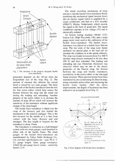
Fig<br />
1 The structure <strong>of</strong> <strong>the</strong> purpose designed buckle<br />
force-transducer.<br />
generated depends on <strong>the</strong> <strong>of</strong>f-set from <strong>the</strong><br />
longitudinal axis <strong>of</strong> <strong>the</strong> strap (Fig. 2). The<br />
amount <strong>of</strong> moment that deforms <strong>the</strong> central<br />
beam is sensed by two stain gauges. The three<br />
metal rods <strong>of</strong> <strong>the</strong> buckle transducer form <strong>the</strong> axis<br />
for thin nylon rollers which help reduce <strong>the</strong><br />
friction between <strong>the</strong> strap and <strong>the</strong> metal rod<br />
during <strong>the</strong> loading and unloading. Ano<strong>the</strong>r<br />
purpose <strong>of</strong> <strong>the</strong> nylon rollers is to increase <strong>the</strong><br />
amount <strong>of</strong> strap <strong>of</strong>f-set which will increase <strong>the</strong><br />
sensitivity <strong>of</strong> <strong>the</strong> transducer without significant<br />
change <strong>of</strong> <strong>the</strong> strap length.<br />
The buckle force-transducer is fitted over <strong>the</strong><br />
strap <strong>of</strong> <strong>the</strong> thoracic pad just behind <strong>the</strong><br />
attachment to <strong>the</strong> anterior outrigger. This is <strong>the</strong><br />
best location for <strong>the</strong> buckle as it is free from<br />
contact with <strong>the</strong> body, thoracic pad and<br />
outrigger. The free length <strong>of</strong> location for <strong>the</strong><br />
transducer is about 35mm.<br />
The transducer is connected as a half-bridged<br />
system with two strain gauges, each furnished to<br />
ei<strong>the</strong>r side <strong>of</strong> <strong>the</strong> buckle frame. The strain<br />
gauges <strong>of</strong> <strong>the</strong> buckle force-transducer are<br />
manufactured by Tokyo Sokki Kenkyujo Co.,<br />
Ltd. and <strong>the</strong>ir specifications are - type: FLA- 3-<br />
23, gauge length: 3mm, gauge resistance:<br />
120±0.3Ω and gauge factor (strain - sensitivity<br />
factor): 2.15.<br />
The whole recording mechanism <strong>of</strong> strap<br />
tension is that <strong>the</strong> buckle force-transducer firstly<br />
transforms <strong>the</strong> mechanical signal (tension force)<br />
into an electric signal which is amplified by a<br />
single conditioner, and <strong>the</strong>n to a XYt recorder<br />
(PM8272, Philips, Ne<strong>the</strong>rlands) which records<br />
<strong>the</strong> signal in <strong>the</strong> form <strong>of</strong> graph plot. The signal<br />
conditioner operates at low voltage (3V) and is<br />
electrically isolated.<br />
An Instron testing machine (Model 1122,<br />
Instron Ltd., High Wycombe, UK) and a strain<br />
gauge meter were used in <strong>the</strong> calibration <strong>of</strong> <strong>the</strong><br />
buckle force-transducer. The buckle forcetransducer<br />
was placed on a double-layer Dacron<br />
strap. The two ends <strong>of</strong> <strong>the</strong> strap were firmly<br />
anchored via special grips to <strong>the</strong> load cell (to<br />
simulate <strong>the</strong> condition as in <strong>the</strong> spinal orthosis).<br />
The strap was loaded in tension from 0 to 300 N<br />
(normal strap tension estimated to be less than<br />
200 N) and <strong>the</strong>n unloaded. The loading and<br />
unloading rate was 10mm/min. Hysteresis was<br />
observed which may be due to <strong>the</strong> elastic<br />
properties <strong>of</strong> <strong>the</strong> Dacron strap, <strong>the</strong> friction<br />
between <strong>the</strong> strap and buckle transducer,<br />
eccentricity in <strong>the</strong> nylon rollers or <strong>the</strong> non-rigid<br />
frame structure. These adverse factors have been<br />
minimised by pre-conditioning <strong>the</strong> Dacron strap,<br />
using concentric nylon rollers and increasing <strong>the</strong><br />
buckle frame rigidity. After <strong>the</strong> above<br />
improvements, <strong>the</strong> degree <strong>of</strong> hysteresis has been<br />
reduced to an acceptable level (Fig. 3).<br />
Fig. 2. Force diagram <strong>of</strong> <strong>the</strong> buckle force-transducer.