CLC fa2005.pdf - Odeon
CLC fa2005.pdf - Odeon
CLC fa2005.pdf - Odeon

You also want an ePaper? Increase the reach of your titles
YUMPU automatically turns print PDFs into web optimized ePapers that Google loves.
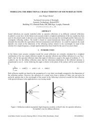
Forum Acusticum 2005 Budapest<br />
Christensen, Rindel<br />
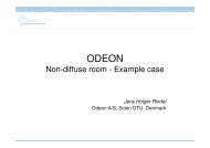
log(E)<br />
Scattering coefficient into account. If scattering is zero<br />
then the orientation of the Oblique Lambert source is<br />
found by Snell’s Law, if the scattering coefficient is<br />
one then the orientation is that of the traditional<br />
Lambert source and finally for all cases in-between the<br />
orientation is determined by the vector found using the<br />
Vector Based Scattering method.<br />
fl<br />
fw<br />
Log(frequency)<br />
Figure 5: Energy reflected from a free suspended<br />
surface given the dimensions l·w. At high frequencies<br />
the surface reflects energy specularily (red), at low<br />
frequencies, energy is assumed to be scattered (blue).<br />
f w is the upper specular cut off frequency defined by<br />
the shortest dimension of the surface, f l is the lower<br />
cutoff frequency which is defined by the length of the<br />
surface.<br />
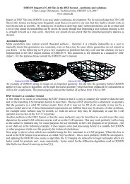
As can be seen, scattering caused by diffraction is a<br />
function of a number of parameters of which some of<br />
them are not known before the actual calculation takes<br />
place. An example is that oblique angles of incidence<br />
leads to increased scattering whereas parallel walls<br />
leads to low scattering and sometimes flutter echoes.<br />
Another example is indicated by the characteristic<br />
distance a*, if source or receiver is close to a surface,<br />
this surface may provide a specular reflection even if<br />
its small, on the other hand if far from away it will only<br />
provide scattered sound, s d ≈1.<br />
3.3 Oblique Lambert<br />
In the ray-tracing process, a number if secondary<br />
sources are generated at the collision points between<br />
walls and the rays traced. It has not been covered yet<br />
which directivity to assign to these sources. A straight<br />
away solution which is the one we have been using up<br />
till now is to assign Lambert directivity patterns, that<br />
is, the cosine directivity which is a model for diffuse<br />
area radiation. However the result would be that the<br />
last reflection from the secondary sources to the actual<br />
receiver point is handled with 100% scattering, no<br />
matter actual scattering properties for the reflection.<br />
This is not the optimum solution, in fact when it comes<br />
to the last reflection path from wall to receiver we<br />
know not only the incident path length to the wall also<br />
the path length from the wall to the receiver is<br />
available, allowing a better estimate of the<br />
characteristic distance a* than was the case in the raytracing<br />
process where d refl was assumed to be equal to<br />
d inc . So which directivity to assign to the secondary<br />
sources? We propose a directivity pattern which we<br />
will call Oblique Lambert. Reusing the concept of<br />
Vector based scattering, an orientation of our Lambert<br />
sources can be obtained taking the Reflection Based<br />
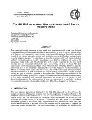
Shadow zone<br />
Oblique angle<br />
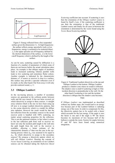
Figure 6: Traditional Lambert directivity at the top and<br />
Oblique Lambert at the bottom. Oblique Lambert<br />
produces a shadow zone where no sound is reflected.<br />
The shadow zone is small if scattering is high or if the<br />
incident direction is perpendicular to the wall. On the<br />
other hand if scattering is low and the incident<br />
direction is oblique then the shadow zone becomes<br />
large.<br />
If Oblique Lambert was implemented as described<br />
without any further steps, this would lead to an energy<br />
loss because part of the Lambert balloon is radiating<br />
energy out of the room. In order to compensate for this,<br />
the directivity pattern has to be scaled with a factor<br />
which accounts for the lost energy. If the angle is zero<br />
the factor is one and if the angle is 90° the factor<br />
becomes its maximum of two because half of the<br />
balloon is outside the room. Factors for angles between<br />
0° and 90° have been found using numerical<br />
integration.