Kodak KAF-4320 Sensor Information
Kodak KAF-4320 Sensor Information
Kodak KAF-4320 Sensor Information

Create successful ePaper yourself
Turn your PDF publications into a flip-book with our unique Google optimized e-Paper software.
DEVICE PERFORMANCE SPECIFICATION<br />
Revision 4.0 MTD/PS-0677<br />
February 11, 2009<br />
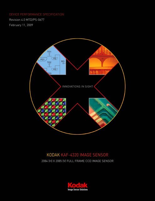
KODAK <strong>KAF</strong>-<strong>4320</strong> IMAGE SENSOR<br />
2084 (H) X 2085 (V) FULL FRAME CCD IMAGE SENSOR
TABLE OF CONTENTS<br />
Summary Specification ...............................................................................................................................................................4<br />
Description ..................................................................................................................................................................................4<br />
Applications .................................................................................................................................................................................4<br />
Ordering <strong>Information</strong> ..................................................................................................................................................................5<br />
Device Description ......................................................................................................................................................................6<br />
Architecture.................................................................................................................................................................................6<br />
Image Acquisition........................................................................................................................................................................8<br />
Charge Transport ........................................................................................................................................................................8<br />
Output Structure......................................................................................................................................................................8<br />
Dark Reference Pixels.............................................................................................................................................................8<br />
Dummy Pixels..........................................................................................................................................................................8<br />
Physical Description....................................................................................................................................................................9<br />
Pin Description and Device Orientation..................................................................................................................................9<br />
Imaging Performance ............................................................................................................................................................... 11<br />
Electro Optical Specifications ...............................................................................................................................................11<br />
Specifications ............................................................................................................................................................................11<br />
Typical Performance Curves..................................................................................................................................................... 13<br />
Linearity .....................................................................................................................................................................................15<br />
CCD Output................................................................................................................................................................................16<br />
Noise..........................................................................................................................................................................................17<br />
CCD amplifier ........................................................................................................................................................................17<br />
System noise..........................................................................................................................................................................17<br />
Temperature dependence of the noise floor........................................................................................................................17<br />
Noise Versus Frequency .......................................................................................................................................................18<br />
Performance Versus Temperature.......................................................................................................................................18<br />
Defect Definitions...................................................................................................................................................................... 20<br />
Operationing Conditions............................................................................................................................................................20<br />
Specifications ............................................................................................................................................................................20<br />
Operation................................................................................................................................................................................... 21<br />
Absolute Maximum Ratings......................................................................................................................................................21<br />
Equivalent Input Circuits...........................................................................................................................................................21<br />
DC Bias Operating Conditions ..................................................................................................................................................22<br />
AC Operating Conditions...........................................................................................................................................................23<br />
AC Timing Conditions................................................................................................................................................................24<br />
Pixel rate clock waveforms ...................................................................................................................................................25<br />
Timing........................................................................................................................................................................................ 26<br />
Normal Read Out...................................................................................................................................................................26<br />
Power Dissipation .....................................................................................................................................................................27<br />
Amplifier power .....................................................................................................................................................................27<br />
Total Power............................................................................................................................................................................27<br />
CCD Surface Flatness ...........................................................................................................................................................28<br />
Storage and Handling ............................................................................................................................................................... 30<br />
Storage Conditions....................................................................................................................................................................30<br />
ESD ............................................................................................................................................................................................30<br />
Cover Glass Care and Cleanliness ...........................................................................................................................................30<br />
Environmental Exposure...........................................................................................................................................................30<br />
Soldering Recommendations ...................................................................................................................................................30<br />
Mechanical Drawings................................................................................................................................................................ 31<br />
©Eastman <strong>Kodak</strong> Company, 2009 www.kodak.com/go/imagers Revision 4.0 MTD/PS-0677 p2
Completed Assembly ................................................................................................................................................................31<br />
Quality Assurance And Reliability ............................................................................................................................................. 33<br />
Quality Strategy .........................................................................................................................................................................33<br />
Replacement .............................................................................................................................................................................33<br />
Liability of the Supplier .............................................................................................................................................................33<br />
Liability of the Customer...........................................................................................................................................................33<br />
Reliability ...................................................................................................................................................................................33<br />
Test Data Retention...................................................................................................................................................................33<br />
Mechanical.................................................................................................................................................................................33<br />
Warning: Life Support Applications Policy ............................................................................................................................... 33<br />
Revision Changes...................................................................................................................................................................... 34<br />
TABLES OF FIGURES<br />
Figure 1: Block Diagram.................................................................................................................................................................6<br />
Figure 2: Horizontal Seam Cross-Section .....................................................................................................................................7<br />
Figure 3: Output Architecture.........................................................................................................................................................8<br />
Figure 4: Pinout Diagram ...............................................................................................................................................................9<br />
Figure 5: Typical Spectral Response............................................................................................................................................13<br />
Figure 6: Dark Current Temperature Dependence .....................................................................................................................14<br />
Figure 7: Linearity .........................................................................................................................................................................15<br />
Figure 8: Output: Small Signal .....................................................................................................................................................16<br />
Figure 9: CCD Output Large Signal..............................................................................................................................................16<br />
Figure 10: Noise Versus Pixel Rate..............................................................................................................................................18<br />
Figure 11: Noise Versus Temperature – 3 MHz Pixel Rate.........................................................................................................18<br />
Figure 12: Noise Versus Temperature – 1 MHz Pixel Rate.........................................................................................................19<br />
Figure 13: Example Output Structure Load Diagram..................................................................................................................22<br />
Figure 14: Clock Example.............................................................................................................................................................25<br />
Figure 15: Timing Diagrams.........................................................................................................................................................26<br />
Figure 16: Completed Assembly (1 of 2) ......................................................................................................................................31<br />
Figure 17: Completed Assembly (2 of 2) ......................................................................................................................................32<br />
©Eastman <strong>Kodak</strong> Company, 2009 www.kodak.com/go/imagers Revision 4.0 MTD/PS-0677 p3
SUMMARY SPECIFICATION<br />
KODAK <strong>KAF</strong>-<strong>4320</strong> IMAGE SENSOR<br />
2084 (H) X 2085 (V) FULL FRAME CCD IMAGE SENSOR<br />
DESCRIPTION<br />
The KODAK <strong>KAF</strong>-<strong>4320</strong> Image <strong>Sensor</strong> is a high<br />
performance monochrome area CCD (charge-coupled<br />
device) image sensor with 2084H x 2085V photoactive<br />
pixels. It is designed for a wide range of image sensing<br />
applications in the 350 nm to 1000 nm wavelength band.<br />
A dynamic range of >32,000:1 is possible with read out<br />
time less than 0.5 seconds.<br />
The sensor is built with a true two-phase CCD technology<br />
employing a transparent gate. This technology simplifies<br />
the support circuits that drive the sensor, reduces the<br />
dark current without compromising charge capacity, and<br />
significantly increases to optical response compared to<br />
traditional front illuminated full frame sensors.<br />
Twenty-four micron pixels are arranged into an array of<br />
2084x2085 photosites. One quarter of the image is read<br />
from each of four outputs. Each output is driven by a low<br />
impedance two stage source follower that provides a<br />
high conversion gain, allowing low noise at pixel rates of<br />
3MHz per output (net readout rate of 12MHz).<br />
APPLICATIONS<br />
• Medical Imaging<br />
• Scientific Imaging<br />
Parameter<br />
Typical Value<br />
Architecture<br />
Full-Frame CCD<br />
Total Number of Pixels<br />
2092 (H) x 2093 (V)<br />
Number of Active Pixels 2084 (H) x 2085 (V) = approx. 4.3M<br />
Pixel Size<br />
24 µm (H) x 24 µm(V)<br />
Imager Size<br />
50.02 mm (H) x 50.02 mm (V)<br />
Die Size<br />
8.4mm (H) x 5.5mm (V)<br />
Output Sensitivity 10µV/e -<br />
Saturation Signal<br />
500,000 electrons<br />
Readout Noise<br />
20 electrons (3 MHz)<br />
Outputs 4<br />
Dark Current (T = 25° C)
ORDERING INFORMATION<br />
Catalog<br />
Number<br />
Product Name Description Marking Code<br />
4H0476 <strong>KAF</strong>- <strong>4320</strong>-AAA-JP-B1<br />
Monochrome, No Microlens, PGA Package, Taped Clear Cover Glass, no<br />
coatings, Grade 1<br />
4H0477 <strong>KAF</strong>- <strong>4320</strong>-AAA-JP-B2<br />
Monochrome, No Microlens, PGA Package, Taped Clear Cover Glass, no<br />
<strong>KAF</strong>- <strong>4320</strong>-AAA<br />
coatings, Grade 2<br />
(Lot Number)<br />
4H0478 <strong>KAF</strong>- <strong>4320</strong>-AAA-JP-AE<br />
Monochrome, No Microlens, PGA Package, Taped Clear Cover Glass, no<br />
coatings, Engineering Sample<br />
4H0475 KEK-4H0475-<strong>KAF</strong>-<strong>4320</strong>-16-3 Evaluation Board (Complete Kit) N/A<br />
Please see the User’s Manual (MTD/PS-0563) for information on the Evaluation Kit for this part.<br />
Please see ISS Application Note “Product Naming Convention” (MTD/PS-0892) for a full description of naming convention<br />
used for KODAK image sensors.<br />
For all reference documentation, please visit our Web Site at www.kodak.com/go/imagers.<br />
Address all inquiries and purchase orders to:<br />
Image <strong>Sensor</strong> Solutions<br />
Eastman <strong>Kodak</strong> Company<br />
Rochester, New York 14650-2010<br />
Phone: (585) 722-4385<br />
Fax: (585) 477-4947<br />
E-mail: imagers@kodak.com<br />
<strong>Kodak</strong> reserves the right to change any information contained herein without notice. All information furnished by <strong>Kodak</strong> is<br />
believed to be accurate.<br />
©Eastman <strong>Kodak</strong> Company, 2009 www.kodak.com/go/imagers Revision 4.0 MTD/PS-0677 p5
DEVICE DESCRIPTION<br />
ARCHITECTURE<br />
RD<br />
R<br />
VDD<br />
VOUT4<br />
VLG<br />
GND<br />
OG<br />
H1L<br />
H2<br />
H1<br />
1 4 4 1042<br />
1042<br />
4 4 1<br />
4<br />
H1<br />
H2<br />
RD<br />
R<br />
VDD<br />
VOUT3<br />
VLG<br />
VSUB<br />
OG<br />
H1L<br />
V1<br />
V2<br />
V1<br />
V2<br />
V1<br />
V2<br />
V1<br />
V2<br />
GUARD<br />
4<br />
<strong>KAF</strong>-<strong>4320</strong>E<br />
2084H x 2085V*<br />
24µm x 24µm Pixels<br />
4<br />
GUARD<br />
V2<br />
V1<br />
V2<br />
V1<br />
V2<br />
V1<br />
V2<br />
V1<br />
RD<br />
R<br />
VDD<br />
VOUT1<br />
VLG<br />
VSUB<br />
OG<br />
H1L<br />
4 Dark<br />
(Last VCCD Phase = TF2 H1)<br />
1 4 4 1042<br />
1042<br />
4 4 1<br />
H2<br />
H1<br />
H1<br />
H2<br />
* Note: The center row is predominately a 24um x 25um polysilicon<br />
pixel that splits evenly into each half of the array. Thus, each quadrant<br />
will consist of 1046 H x 1047 V rows where the last row will contain<br />
roughly half the signal.<br />
Figure 1: Block Diagram<br />
RD<br />
R<br />
VDD<br />
VOUT2<br />
VLG<br />
VSUB<br />
OG<br />
H1L<br />
©Eastman <strong>Kodak</strong> Company, 2009 www.kodak.com/go/imagers Revision 4.0 MTD/PS-0677 p6
Row 1045<br />
Row 1046<br />
½ Row 1047<br />
½ Row 1047<br />
Row 1046<br />
Row 1045<br />
24um 24um 25um 24um 24um<br />
10um<br />
14um<br />
Poly ITO<br />
++ +++++ ++ +++++ ++++ +++++ ++ +++++ ++<br />
Top<br />
Half<br />
Bottom<br />
Half<br />
Pixel optical<br />
boundary<br />
Figure 2: Horizontal Seam Cross-Section<br />
©Eastman <strong>Kodak</strong> Company, 2009 www.kodak.com/go/imagers Revision 4.0 MTD/PS-0677 p7
IMAGE ACQUISITION<br />
An electronic representation of an image is formed when<br />
incident photons falling on the sensor plane create<br />
electron-hole pairs within the sensor. These photon<br />
induced electrons are collected locally by the formation<br />
of potential wells at each photogate or pixel site. The<br />
number of electrons collected is linearly dependent on<br />
light level and exposure time and non-linearly dependent<br />
on wavelength. When the pixel's capacity is reached,<br />
excess electrons will leak into the adjacent pixels within<br />
the same column. This is termed blooming. During the<br />
integration period, the φV1 and φV2 register clocks are<br />
held at a constant (low) level. See Figure 15 Timing<br />
diagrams.<br />
CHARGE TRANSPORT<br />
Referring again to “Figure 15 Timing Diagrams”, the<br />
integrated charge from each photogate is transported to<br />
the output using a two-step process. Each line (row) of<br />
charge is first transported from the vertical CCD to the<br />
horizontal CCD register using the φV1 and φV2 register<br />
clocks. The horizontal CCD is presented a new line on<br />
the falling edge of φV2 while fH1 is held high. The<br />
horizontal CCD then transports each line, pixel by pixel,<br />
to the output structure by alternately clocking the φH1<br />
and φH2 pins in a complementary fashion. On each<br />
falling edge of φH1L a new charge packet is transferred<br />
onto a floating diffusion and sensed by the output<br />
amplifier.<br />
Dark Reference Pixels<br />
There are 4 light shielded pixels at the beginning of each<br />
line. There are 4 dark lines at the start of every frame<br />
and 4 dark lines at the end of each frame. Since there<br />
are outputs at each of the four, corners, the light shield<br />
will affect the beginning of each line from each output,<br />
and for the first four lines from each of the outputs.<br />
Under normal circumstances, these pixels do not<br />
respond to light. However, dark reference pixels in close<br />
proximity to an active pixel can scavenge signal<br />
depending on light intensity and wavelength and<br />
therefore will not represent the true dark signal.<br />
Dummy Pixels<br />
Within the horizontal shift register are 4-1/2 leading<br />
pixels that are not associated with a column of pixels<br />
within the vertical register. These pixels contain only<br />
horizontal shift register dark current signal and do not<br />
respond to light. A few leading dummy pixels may<br />
scavenge false signal depending on operating conditions.<br />
H2<br />
H1<br />
H2<br />
H1L<br />
Vog<br />
HCCD<br />
Charge<br />
Transfer<br />
VDD<br />
Output Structure<br />
Charge presented to the floating diffusion is converted<br />
into a voltage and current amplified in order to drive offchip<br />
loads. The resulting voltage change seen at the<br />
output is linearly related to the amount of charge placed<br />
on the floating diffusion. Once the signal has been<br />
sampled by the system electronics, the reset gate (φR) is<br />
clocked to remove the signal and the floating diffusion is<br />
reset to the potential applied by Vrd. (See Figure 3 Output<br />
Schematic). More signal at the floating diffusion reduces<br />
the voltage seen at the output pin. In order to activate the<br />
output structure, an off-chip load must be added to the<br />
Vout pin of the device such as shown in Figure 5.<br />
R<br />
Vrd<br />
Vlg<br />
Floating<br />
Diffusion<br />
Source<br />
Follower<br />
#1<br />
Figure 3: Output Architecture<br />
Source<br />
Follower<br />
#2<br />
Vo<br />
If charge binning is desired, the charge can be combined<br />
at the output node or it can be combined in the φH1L<br />
gate and then presented to the output node.<br />
©Eastman <strong>Kodak</strong> Company, 2009 www.kodak.com/go/imagers Revision 4.0 MTD/PS-0677 p8
PHYSICAL DESCRIPTION<br />
Pin Description and Device Orientation<br />
Gnd<br />
øR<br />
OG<br />
øH1L<br />
øH1<br />
øH2<br />
Gnd<br />
Gnd<br />
Gnd<br />
61 60 59 58 57 56 55 54 53<br />
Gnd<br />
Gnd<br />
Gnd<br />
øH2<br />
øH1<br />
øH1L<br />
OG<br />
øR<br />
Gnd<br />
52 51 50 49 48 47 46 45 44<br />
Vrd<br />
Vlg<br />
Vss<br />
Gnd<br />
62<br />
63<br />
64<br />
65<br />
Vout4 66<br />
Vdd<br />
øV2<br />
øV1<br />
Gnd<br />
øV1<br />
øV2<br />
67<br />
68<br />
69<br />
70<br />
71<br />
72<br />
Guard73<br />
øV2<br />
øV1<br />
Gnd<br />
øV1<br />
øV2<br />
Vdd<br />
74<br />
75<br />
76<br />
77<br />
78<br />
79<br />
Vout1 80<br />
Gnd<br />
Vss<br />
Vlg<br />
Vrd<br />
81<br />
82<br />
83<br />
84<br />
Pin 1<br />
1 2 3 4 5 6 7 8 9 10 11 1213141516171819 20<br />
43<br />
42<br />
41<br />
40<br />
39 Vout3<br />
38<br />
37<br />
36<br />
35<br />
34<br />
33<br />
32<br />
31 øV2<br />
30<br />
29<br />
28 øV1<br />
27 øV2<br />
26 Vdd<br />
25 Vout2<br />
24 Gnd<br />
23<br />
22<br />
21<br />
Vrd<br />
Vlg<br />
Vss<br />
Gnd<br />
Vdd<br />
øV2<br />
øV1<br />
Gnd<br />
øV1<br />
øV2<br />
Guard<br />
øV1<br />
Gnd<br />
Vss<br />
Vlg<br />
Vrd<br />
Gnd<br />
øR<br />
OG<br />
øH1L<br />
øH1<br />
øH2<br />
Gnd<br />
Gnd<br />
Gnd<br />
N/C<br />
N/C<br />
Gnd<br />
Gnd<br />
Gnd<br />
øH2<br />
øH1<br />
øH1L<br />
OG<br />
øR<br />
Gnd<br />
Figure 4: Pinout Diagram<br />
©Eastman <strong>Kodak</strong> Company, 2009 www.kodak.com/go/imagers Revision 4.0 MTD/PS-0677 p9
Pin Name Description Pin Name Description<br />
1 GND Substrate (ground) 43 VRD Reset Drain<br />
2 φR Reset Clock 44 GND Substrate (ground)<br />
3 VOG Output gate bias 45 φR Reset Clock<br />
4 φH1L Horizontal CCD Clock – Last phase 46 VOG Output gate bias<br />
5 φH1 Horizontal CCD Clock – Phase 1 47 φH1L Horizontal CCD Clock – Last phase<br />
6 φH2 Horizontal CCD Clock – Phase 2 48 φH1 Horizontal CCD Clock – Phase 1<br />
7 GND Substrate (ground) 49 φH2 Horizontal CCD Clock – Phase 2<br />
8 GND Substrate (ground) 50 GND Substrate (ground)<br />
9 GND Substrate (ground) 51 GND Substrate (ground)<br />
10 N/C No connect 52 GND Substrate (ground)<br />
11 N/C No connect 53 GND Substrate (ground)<br />
12 GND Substrate (ground) 54 GND Substrate (ground)<br />
13 GND Substrate (ground) 55 GND Substrate (ground)<br />
14 GND Substrate (ground) 56 φH2 Horizontal CCD Clock – Phase 2<br />
15 φH2 Horizontal CCD Clock – Phase 2 57 φH1 Horizontal CCD Clock – Phase 1<br />
16 φH1 Horizontal CCD Clock – Phase 1 58 φH1L Horizontal CCD Clock – Last phase<br />
17 φH1L Horizontal CCD Clock – Last phase 59 VOG Output gate bias<br />
18 VOG Output gate bias 60 φR Reset Clock<br />
19 φR Reset Clock 61 GND Substrate (ground)<br />
20 GND Substrate (ground) 62 VRD Reset Drain<br />
21 VRD Reset Drain 63 VLG Amplifier Supply Return<br />
22 VLG Amplifier Supply Return 64 VSS Source follower load gate bias<br />
23 VSS Source follower load gate bias 65 GND Substrate (ground)<br />
24 GND Substrate (ground) 66 Vout4 Amplifier output<br />
25 Vout2 Amplifier output 67 VDD Amplifier Supply<br />
26 VDD Amplifier Supply 68 φV2 Vertical CCD Clock -Phase 2<br />
27 φV2 Vertical CCD Clock - Phase 2 69 φV1 Vertical CCD Clock - Phase 1<br />
28 φV1 Vertical CCD Clock - Phase 1 70 GND Substrate (ground)<br />
29 GND Substrate (ground) 71 φV1 Vertical CCD Clock - Phase 1<br />
30 φV1 Vertical CCD Clock - Phase 1 72 φV2 Vertical CCD Clock - Phase 2<br />
31 φV2 Vertical CCD Clock - Phase 73 Guard Guard Ring<br />
32 Guard Guard Ring 74 φV2 Vertical CCD Clock - Phase<br />
33 φV2 Vertical CCD Clock - Phase 75 φV1 Vertical CCD Clock - Phase 1<br />
34 φV1 Vertical CCD Clock - Phase 1 76 GND Substrate (ground)<br />
35 GND Substrate (ground) 77 φV1 Vertical CCD Clock - Phase 1<br />
36 φV1 Vertical CCD Clock - Phase 1 78 φV2 Vertical CCD Clock - Phase 2<br />
37 φV2 Vertical CCD Clock - Phase 79 VDD Amplifier Supply<br />
38 VDD Amplifier Supply 80 Vout1 Amplifier output<br />
39 Vout3 Amplifier output 81 GND Substrate (ground)<br />
40 GND Substrate (ground) 82 VSS Source follower load gate bias<br />
41 VSS Source follower load gate bias 83 VLG Source follower load gate bias<br />
42 VLG Amplifier Supply Return 84 VRD Reset Drain<br />
Note: Like named pins (e.g. Vss) should be connected to the same supply.<br />
©Eastman <strong>Kodak</strong> Company, 2009 www.kodak.com/go/imagers Revision 4.0 MTD/PS-0677 p10
IMAGING PERFORMANCE<br />
Electro Optical Specifications<br />
All values measured at 25°C, and nominal operating conditions. These parameters exclude defective pixels.<br />
SPECIFICATIONS<br />
Description Symbol Min. Nom. Max. Units Notes Verification Plan<br />
Saturation Signal<br />
Vertical CCD capacity<br />
Horizontal CCD capacity<br />
Output Node capacity<br />
Nsat<br />
650000<br />
850000<br />
550000<br />
electrons/pixel<br />
design 10<br />
500000<br />
1<br />
Quantum Efficiency (see Figure 4 Spectral response) design 10<br />
Photoresponse Non-Linearity PRNL < 1.0 2.0 % 2 design 10<br />
Photoresponse Non-Uniformity PRNU 0.8 2.0 % 3 design 10<br />
Channel to channel Gain Difference G 0.2 5 % 8 die 9<br />
Dark Signal Jdark 2507 54015 electrons/pixel/sec 4 die 9<br />
Dark Signal Doubling Temperature 6.3 7 o C design 10<br />
Dark Signal Non-Uniformity DSNU 300 540 electrons/pixel/sec 5 die 9<br />
Dynamic Range DR 86 87.5 dB 6 design 10<br />
Output Amplifier DC Offset Vodc Vrd-4 Vrd -3 Vrd -2 V die 9<br />
Output Amplifier Sensitivity Vout/Ne~ 9 10 11 uV/e~ design 10<br />
Output Amplifier output Impedance Zout 150 Ohms die 9<br />
Noise Floor ne~ 17 24 electrons 7 design 10<br />
©Eastman <strong>Kodak</strong> Company, 2009 www.kodak.com/go/imagers Revision 4.0 MTD/PS-0677 p11
Notes:<br />
1. The maximum output video amplitude limits the<br />
charge capacity and dynamic range. The<br />
maximum charge capacity is determined from a<br />
photon transfer measurement and is defined as<br />
the point where the mean-variance fails to<br />
demonstrate the theoretical behavior.<br />
2. Worst case deviation from straight line fit,<br />
between 0.1% and 95% of Vsat.<br />
3. One Sigma deviation of a 1042 x 1042 sample<br />
(data from one output) when the CCD is<br />
illuminated uniformly at half of saturation,<br />
excluding defective pixels. [100 * (std<br />
deviation/average)]<br />
4. Average of all pixels with no illumination at 25 o C.<br />
5. Average dark signal of any of 16 x 16 blocks<br />
within the sensor (each block is 130x 130 pixels).<br />
6. The dynamic range limited by the noise of the<br />
output amplifier (i.e. at temperatures less than –<br />
10 C), pixel frequency = 3MHz, bandwidth = 10<br />
MHz.<br />
7. Noise floor of the CCD amplifier assuming<br />
correlated double sampling, pixel frequency =<br />
3MHz, and bandwidth = 10MHz.<br />
8. ∆G = abs (100 * (1 – [response of a channel]/<br />
[average response of all four channels])). The<br />
specified gain difference is the combination of all<br />
the gain errors on the CCD sensor and the<br />
analog signal processing in the test system.<br />
9. A parameter that is measured on every sensor<br />
during production testing.<br />
10. A parameter that is quantified during the design<br />
verification activity.<br />
©Eastman <strong>Kodak</strong> Company, 2009 www.kodak.com/go/imagers Revision 4.0 MTD/PS-0677 p12
TYPICAL PERFORMANCE CURVES<br />
<strong>KAF</strong>-<strong>4320</strong>E<br />
1<br />
Absolute Quantum Efficiency<br />
0.9<br />
0.8<br />
0.7<br />
0.6<br />
0.5<br />
0.4<br />
0.3<br />
0.2<br />
0.1<br />
0<br />
300 400 500 600 700 800 900 1000 1100 1200<br />
Wavelength (nm)<br />
Figure 5: Typical Spectral Response<br />
©Eastman <strong>Kodak</strong> Company, 2009 www.kodak.com/go/imagers Revision 4.0 MTD/PS-0677 p13
<strong>KAF</strong>-<strong>4320</strong> Dark Current<br />
1000<br />
el/pix/sec<br />
100<br />
10<br />
measured<br />
Tdbl=6.4 C<br />
1<br />
-20 -10 0 10 20 30<br />
Temperature (C)<br />
Figure 6: Dark Current Temperature Dependence<br />
©Eastman <strong>Kodak</strong> Company, 2009 www.kodak.com/go/imagers Revision 4.0 MTD/PS-0677 p14
LINEARITY<br />
Figure 7 Linearity shows a typical result from measuring the signal response as a function of integration time, while the<br />
illumination level is constant. The data is fit in log space to give equal weighting between low and high signal levels. A<br />
perfectly linear system would have a slope of 1.00 in log space. The slope in the fit is allowed to deviate from the ideal by a<br />
small amount. Typical values of the slope are between 1.00 and 1.02. The deviation from linear is defined as:<br />
%dev = abs(100 * [measured value-fit value]/ fit value).<br />
<strong>KAF</strong>-<strong>4320</strong> Linearity<br />
1000000<br />
100000<br />
Signal (electrons/pixel)<br />
10000<br />
1000<br />
100<br />
10<br />
1<br />
0.1<br />
measured<br />
fit<br />
% dev from fit<br />
0.01<br />
1 10 100 1000 10000 100000<br />
Time (msec)<br />
Figure 7: Linearity<br />
©Eastman <strong>Kodak</strong> Company, 2009 www.kodak.com/go/imagers Revision 4.0 MTD/PS-0677 p15
CCD OUTPUT<br />
The following figures show typical CCD video at the output of the CCD and at the input of the analog to digital converter<br />
(A/D) in the test system. Bandwidth limiting is applied at the A/D input to minimize the noise floor.<br />
Figure 8: Output: Small Signal<br />
Figure 9: CCD Output Large Signal<br />
©Eastman <strong>Kodak</strong> Company, 2009 www.kodak.com/go/imagers Revision 4.0 MTD/PS-0677 p16
NOISE<br />
The CCD amplifier noise floor, the CCD dark current<br />
during readout, and other system components such as<br />
the analog-digital converter dictate the total system<br />
noise.<br />
CCD amplifier<br />
The noise contributed by the output amplifier is<br />
determined from the amplifier’s noise power spectrum,<br />
the system bandwidth, and any other analog processing.<br />
Correlated double sampling is a standard analog<br />
processing technique used with CCDs and it is assumed<br />
that it is used for all of the rest of the calculations and<br />
results in this document.<br />
System noise<br />
The total noise will be the combination of the CCD and<br />
the noise contributed by other components in the<br />
processing circuitry. The total noise, dominated by the<br />
CCD and the A/D converter is also shown in Figure 9<br />
Noise versus pixel rate”. The measured vales were<br />
obtained using a system that employed Datel 16 bit<br />
analog to digital converters, the ADS 931 and ADS933.<br />
The system noise obtained matched the Datel<br />
specifications exactly and was similar and slightly lower<br />
than the CCD noise contribution. The table below shows<br />
the results and good agreement between the expected<br />
and measured results for the CCD alone and the CCD in<br />
the system at 1MHz and 3 MHz. The values in the table<br />
are in electrons referred to the CCD amplifier input.<br />
Frequency<br />
CCD Measured<br />
Noise<br />
1.00E+06 12 16.2<br />
3.00E+06 17.3 22.6<br />
Temperature dependence of the noise floor<br />
CCD+System Datel<br />
ADS93x Measured<br />
The temperature dependence of the noise floor is<br />
dictated primarily by the dark current generated during<br />
the readout time for the CCD. Figure 11 Noise versus<br />
temperature - 3 MHz pixel rate” and Figure 12 Noise<br />
versus temperature - 1 MHz pixel rate” show the<br />
expected dynamic range of the <strong>KAF</strong>-<strong>4320</strong>E as a function<br />
of temperature for two pixel rates, 1MHz and 3 MHz. The<br />
dynamic range was calculated using the measured<br />
amplifier and system noise values, the expected dark<br />
current performance, and the saturation signal of the<br />
<strong>KAF</strong>-<strong>4320</strong>E. At 25 C the dark current shot noise can<br />
contribute from 12 to 50 electrons and dominate the<br />
noise floor. The maximum dynamic range can be<br />
achieved at temperatures < -10 C for these read out<br />
frequencies.<br />
©Eastman <strong>Kodak</strong> Company, 2009 www.kodak.com/go/imagers Revision 4.0 MTD/PS-0677 p17
Noise Versus Frequency<br />
Pixel Rate Dependency of Noise<br />
25<br />
Noise (electrons)<br />
20<br />
15<br />
10<br />
5<br />
0<br />
0.0E+00 5.0E+05 1.0E+06 1.5E+06 2.0E+06 2.5E+06 3.0E+06 3.5E+06<br />
Pixel rate (MHz)<br />
CCD noise - calculated<br />
CCD+system - measured<br />
CCD noise measured<br />
Figure 10: Noise Versus Pixel Rate<br />
Performance Versus Temperature<br />
<strong>KAF</strong>-<strong>4320</strong> System Dynamic Range<br />
16<br />
15.5<br />
total system<br />
CCD<br />
Dynamic Range (Bits)<br />
15<br />
14.5<br />
14<br />
13.5<br />
13<br />
12.5<br />
12<br />
-50 -40 -30 -20 -10 0 10 20 30<br />
Temperature (C)<br />
total system noise: CCD readout dark current + CCD amplifier + A/D converter<br />
(Datel 933 16 bit converter)<br />
Figure 11: Noise Versus Temperature – 3 MHz Pixel Rate<br />
©Eastman <strong>Kodak</strong> Company, 2009 www.kodak.com/go/imagers Revision 4.0 MTD/PS-0677 p18
<strong>KAF</strong>-<strong>4320</strong> System Dynamic Range<br />
16<br />
15.5<br />
total system<br />
CCD<br />
Dynamic Range (Bits)<br />
15<br />
14.5<br />
14<br />
13.5<br />
13<br />
12.5<br />
12<br />
-50 -40 -30 -20 -10 0 10 20 30<br />
Temperature (C)<br />
total system noise: CCD readout dark current + CCD amplifier + A/D converter<br />
(Datel 931 16 bit converter)<br />
Figure 12: Noise Versus Temperature – 1 MHz Pixel Rate<br />
©Eastman <strong>Kodak</strong> Company, 2009 www.kodak.com/go/imagers Revision 4.0 MTD/PS-0677 p19
DEFECT DEFINITIONS<br />
OPERATIONING CONDITIONS<br />
Cosmetic tests performed at T=25 o C<br />
SPECIFICATIONS<br />
Grade Point Defects Cluster Defects Columns Double Column<br />
C1
OPERATION<br />
ABSOLUTE MAXIMUM RATINGS<br />
Notes:<br />
Description Symbol Min. Max. Units Notes<br />
Diode Pin Voltages Vdiode 0 25 V 1,2<br />
Gate Pin Voltages –Type 1 Vgate1 -17 17 V 1,3,7<br />
Gate Pin Voltages – Type 2 Vgate2 0 17 V 1,4,7<br />
Output Bias Current Iout -10 mA 5<br />
Output Load Capacitance Cload 15 pF 5<br />
Storage Temperature T 100 oC<br />
Humidity RH 5 90 % 6<br />
1. Referenced to pin Vsub or between each pin in this group.<br />
2. Includes pins: Vrd, Vdd, Vss, Vout.<br />
3. Includes pins: φV1, φV2, φH1, φH2, φH1L,<br />
4. Includes pins: Vog, Vlg. φR.<br />
5. Avoid shorting output pins to ground or any low impedance source during operation.<br />
6. T=25°C. Excessive humidity will degrade MTTF.<br />
7. This sensor contains gate protection circuits to provide protection against ESD events. The circuits will turn on<br />
when greater than 18 volts appears between any two gate pins. Permanent damage can result if excessive current<br />
is allowed to flow under these conditions.<br />
EQUIVALENT INPUT CIRCUITS<br />
Many of the pins contain a form of gate protection to prevent damage from electrostatic discharge. These take the form of<br />
zener diodes that prevent the voltage differences between gates from becoming large enough to damage the sensor.<br />
Isolated gates such as øR, and Vlg require only protection between the gate and the sensor substrate.<br />
øH1<br />
øH2<br />
øH1L<br />
Vog<br />
Sub<br />
øV1<br />
øV2<br />
Sub<br />
Sub<br />
Sub<br />
øR<br />
Vlg<br />
©Eastman <strong>Kodak</strong> Company, 2009<br />
www.kodak.com/go/imagers<br />
Revision 4.0 MTD/PS-0677 p21
DC BIAS OPERATING CONDITIONS<br />
Notes:<br />
Description Symbol Min. Nom. Max Units Max DC Current (mA) Notes<br />
Reset Drain Vrd 18.5 V 0.01 2<br />
Output Amplifier Return Vss 2.0 V 1 3<br />
Output Amplifier Supply Vdd 21 V Iout 2<br />
Substrate GND 0 V<br />
Output Gate Vog 0 V 0.01 3<br />
Output amplifier load gate Vlg Vss Vss+1.0 Vss+1.2 V 0.01<br />
Guard ring Vguard 10 V 3<br />
Amplifier Output Current Iout -5 -10 mA - 1<br />
1. An output load sink must be applied to Vout to activate output amplifier - see Figure below.<br />
2. Voltage tolerance is 2% (actual voltage should be nominal +/- tolerance)<br />
3. Voltage tolerance is 5% (actual voltage should be nominal +/- tolerance)<br />
Vdd<br />
0.1uF<br />
Vout<br />
~5ma<br />
2N3904 or equivalent<br />
Buffered Output<br />
140 Ω<br />
1k Ω<br />
Figure 13: Example Output Structure Load Diagram<br />
This provides a constant current source for the CCD 2-stage source follower circuit.<br />
©Eastman <strong>Kodak</strong> Company, 2009 www.kodak.com/go/imagers Revision 4.0 MTD/PS-0677 p22
AC OPERATING CONDITIONS<br />
Description Symbol Level Nom. Units Effective Capacitance Notes<br />
Vertical CCD Clock - Phase 1 φV1 Low Level Clock Amplitude<br />
Vertical CCD Clock - Phase 2 φV2 Low Level Clock Amplitude<br />
Horizontal CCD Clock - Phase 1 φH1 Low Level Clock Amplitude<br />
Horizontal CCD Clock –Last Gate φH1L Low Level Clock Amplitude<br />
Horizontal CCD Clock - Phase 2 φH2 Low Level Clock Amplitude<br />
Reset Clock φR Low Level Clock Amplitude<br />
Notes:<br />
1. All pins draw less than 10uA DC current.<br />
2. Capacitance values relative to VSUB.<br />
-8.0<br />
8.0<br />
-8.0<br />
8<br />
0<br />
10.0<br />
-3.0<br />
10.0<br />
-3.0<br />
10.0<br />
2.0<br />
12.0<br />
3. Voltage tolerance is 2% (actual voltage should be nominal +/- tolerance)<br />
4. Voltage tolerance is 5% (actual voltage should be nominal +/- tolerance)<br />
5. Total clock capacitance is 4 * 75 nF = 300 nF.<br />
6. Total clock capacitance is 4 * 150 pF = 600 pF<br />
7. Total clock capacitance is 4 * 100 pF = 400 pF<br />
V<br />
V<br />
V<br />
V<br />
V<br />
V<br />
V<br />
V<br />
V<br />
V<br />
V<br />
V<br />
75 nF (each of ØV1 pins 30, 34, 71, 75) 4,5<br />
75 nF (each of ØV2 pins 31, 33, 72, 74) 4,5<br />
150pF (each of ØH1 pins 5, 16, 48, 57) 3,6<br />
10pF 3<br />
100pF (each of ØH2 pins 6, 15, 49, 56) 3,7<br />
5pF 3<br />
©Eastman <strong>Kodak</strong> Company, 2009 www.kodak.com/go/imagers Revision 4.0 MTD/PS-0677 p23
AC TIMING CONDITIONS<br />
Notes:<br />
Description Symbol Min. Nom. Max. Units Notes<br />
φH1, φH2 Clock Frequency f H 3 3 MHz 1, 2, 3<br />
Pixel Period (1 Count) t e 333 333 ns<br />
φH1, φH2 Setup Time tφHS 10 10 us<br />
φV1, φV2 Clock Pulse Width tφV 30 30 us 2<br />
Reset Clock Pulse Width tφR 20 ns 4<br />
Readout Time t readout 470.3 470.3 ms 5<br />
Integration Time t int 6<br />
Line Time t line 449.6 449.6 us 7<br />
1. 50% duty cycle values.<br />
2. CTE will degrade above the nominal frequency.<br />
3. Rise and fall times (10/90% levels) should be limited to 5-10% of clock period. Crossover of register clocks should<br />
be between 40-60% of amplitude.<br />
4. φR should be clocked continuously.<br />
5. t readout = ( 1046* t line )<br />
6. Integration time is user specified. Longer integration times will degrade noise performance due to dark signal<br />
fixed pattern and shot noise.<br />
7. tline = ( 3* tφ V ) + tφ HS + ( 1050* t e )<br />
8. When combining the image from the upper half of the device with that from the lower half, line 1047 from each<br />
must be added together and gained (approx. 1.2X) to match the other 1046 lines.<br />
©Eastman <strong>Kodak</strong> Company, 2009 www.kodak.com/go/imagers Revision 4.0 MTD/PS-0677 p24
Pixel rate clock waveforms<br />
For best performance, the horizontal clocks should be damped, similar to those shown in Figure 14. The clocks in this<br />
figure were generated using a 50 ohm output impedance clock driver. Excessively fast clocks can result in a higher noise<br />
floor.<br />
Figure 14: Clock Example<br />
©Eastman <strong>Kodak</strong> Company, 2009 www.kodak.com/go/imagers Revision 4.0 MTD/PS-0677 p25
TIMING<br />
Normal Read Out<br />
Frame Timing – per quadrant ( each output contains one half of the lines)<br />
tint<br />
tReadout<br />
1 Frame = 1046 Lines<br />
φV1<br />
φV2<br />
Line 1 2 1045 1046<br />
φH1, φH1L<br />
φH2<br />
Line Timing<br />
Pixel Timing<br />
tφR<br />
φV1<br />
tφV<br />
φR<br />
φV2<br />
tφV<br />
φH1,<br />
φH1L<br />
φH1,<br />
φH1L<br />
φH2<br />
tφHS<br />
te<br />
φH2<br />
te<br />
Vpix<br />
1 count<br />
φR<br />
1050 counts<br />
Vout<br />
Vsat<br />
Vdark<br />
Vodc<br />
Vsub<br />
Line Content – per quadrant (each output<br />
contains one half of a line)<br />
1-4 5-8 9-1050<br />
Vsat<br />
Vdark<br />
Vpix<br />
Vodc<br />
Vsub<br />
Saturated pixel video output<br />
Video output signal in no light situation, not zero due to<br />
Pixel video output signal level, more electrons =more<br />
Video level offset with respect to<br />
Analog<br />
Photoactive<br />
Dummy Pixels<br />
* See Image Aquisition section<br />
Dark Reference<br />
Figure 15: Timing Diagrams<br />
For binning, please call an Eastman <strong>Kodak</strong> Company, ISS Sales and Marketing Representative.<br />
©Eastman <strong>Kodak</strong> Company, 2009 www.kodak.com/go/imagers Revision 4.0 MTD/PS-0677 p26
POWER DISSIPATION<br />
The power dissipated by the CCD clocks is calculated using the formula:<br />
Power = CV 2 f<br />
Where C is the capacitance in farads, V is the clock amplitude in volts, and f is the frequency in Hz.<br />
Amplifier power<br />
The power dissipated by amplifiers is calculated by Power = I*V where I is the current and V is the voltage drop on the CCD.<br />
The sensor contains two stage source followers. The first stage draws approximately 250 micro amps and the voltage drop<br />
is Vdd – Vss. The second stage sources much more current, approximately 5mA while the voltage drop on the sensor is<br />
much smaller, Vdd – Vout where Vout ~ Vrd.<br />
Total Power<br />
The table below shows the power dissipated at three different pixel frequencies. For each of these cases the amplifier<br />
operating conditions are held constant so its contribution is not frequency dependent. The time for the vertical clock<br />
transfers is also held constant (90 microseconds per line) but the line time changes depending on the pixel rate.<br />
Contributor<br />
Pixel rate<br />
Notes<br />
500 kHz 1 MHz 3MHz Pixel rate<br />
Amplifiers 120 mW 120 mW 120 mW Total of 4 outputs<br />
Hccd 60 mW 120 mW 360 mW<br />
Vccd 62 mW 121 mW 297 mW<br />
Total 241 mW 361 mW 776 mW<br />
©Eastman <strong>Kodak</strong> Company, 2009 www.kodak.com/go/imagers Revision 4.0 MTD/PS-0677 p27
CCD Surface Flatness<br />
The flatness of the die is defined as a peak-to-peak distortion in the image sensor surface. The parallelism between the<br />
image sensor surface and any of the package components is not specified or guaranteed. The non-parallelism is removed<br />
when measuring the distortion in the image sensor surface.<br />
Min. Nom. Max. Units<br />
Die Flatness Peak to peak distortion 8.8 12.0 microns<br />
Some examples of profiles of some typical image sensors surfaces are shown below.<br />
©Eastman <strong>Kodak</strong> Company, 2009 www.kodak.com/go/imagers Revision 4.0 MTD/PS-0677 p28
©Eastman <strong>Kodak</strong> Company, 2009 www.kodak.com/go/imagers Revision 4.0 MTD/PS-0677 p29
STORAGE AND HANDLING<br />
STORAGE CONDITIONS<br />
Description Symbol Minimum Maximum Units Notes<br />
Storage<br />
Temperature<br />
TST -100 C +80 c °C 1<br />
Humidity RH -70 +50 % 2<br />
Notes:<br />
1. Long-term exposure toward the maximum temperature will<br />
accelerate color filter degradation.<br />
2. T=25ºC. Excessive humidity will degrade MTTF<br />
ESD<br />
1. This device contains limited protection against<br />
Electrostatic Discharge (ESD). CCD image<br />
sensors can be damaged by electrostatic<br />
discharge. Failure to do so may alter device<br />
performance and reliability.<br />
2. Devices should be handled in accordance with<br />
strict ESD procedures for Class 0 (
MECHANICAL DRAWINGS<br />
COMPLETED ASSEMBLY<br />
Figure 16: Completed Assembly (1 of 2)<br />
©Eastman <strong>Kodak</strong> Company, 2009 www.kodak.com/go/imagers Revision 4.0 MTD/PS-0677 p31
Figure 17: Completed Assembly (2 of 2)<br />
©Eastman <strong>Kodak</strong> Company, 2009 www.kodak.com/go/imagers Revision 4.0 MTD/PS-0677 p32
QUALITY ASSURANCE AND RELIABILITY<br />
QUALITY STRATEGY<br />
All image sensors will conform to the specifications<br />
stated in this document. This will be accomplished<br />
through a combination of statistical process control and<br />
inspection at key points of the production process.<br />
Typical specification limits are not guaranteed but<br />
provided as a design target. For further information refer<br />
to ISS Application Note MTD/PS-0292, Quality and<br />
Reliability.<br />
REPLACEMENT<br />
All devices are warranted against failure in accordance<br />
with the terms of Terms of Sale. This does not include<br />
failure due to mechanical and electrical causes defined<br />
as the liability of the customer below.<br />
LIABILITY OF THE SUPPLIER<br />
A reject is defined as an image sensor that does not<br />
meet all of the specifications in this document upon<br />
receipt by the customer.<br />
LIABILITY OF THE CUSTOMER<br />
Damage from mechanical (scratches or breakage),<br />
electrostatic discharge (ESD) damage, or other electrical<br />
misuse of the device beyond the stated absolute<br />
maximum ratings, which occurred after receipt of the<br />
sensor by the customer, shall be the responsibility of the<br />
customer.<br />
RELIABILITY<br />
<strong>Information</strong> concerning the quality assurance and<br />
reliability testing procedures and results are available<br />
from the Image <strong>Sensor</strong> Solutions and can be supplied<br />
upon request. For further information refer to ISS<br />
Application Note MTD/PS-0292, Quality and Reliability.<br />
TEST DATA RETENTION<br />
Image sensors shall have an identifying number<br />
traceable to a test data file. Test data shall be kept for a<br />
period of 2 years after date of delivery.<br />
MECHANICAL<br />
The device assembly drawing is provided as a reference.<br />
The device will conform to the published package<br />
tolerances.<br />
<strong>Kodak</strong> reserves the right to change any information contained herein without notice. All information furnished by <strong>Kodak</strong> is<br />
believed to be accurate.<br />
WARNING: LIFE SUPPORT APPLICATIONS POLICY<br />
<strong>Kodak</strong> image sensors are not authorized for and should not be used within Life Support Systems without the specific<br />
written consent of the Eastman <strong>Kodak</strong> Company. Product warranty is limited to replacement of defective components and<br />
does not cover injury or property or other consequential damages.<br />
©Eastman <strong>Kodak</strong> Company, 2009 www.kodak.com/go/imagers Revision 4.0 MTD/PS-0677 p33
REVISION CHANGES<br />
Revision Number<br />
Description of Changes<br />
A<br />
Initial very preliminary release fro purposes of discussion.<br />
B<br />
Filled in timing conditions table, updated pin out and package drawings. These are new.<br />
C<br />
New package drawing. One dimension changed. Added some performance parameters that will need to be characterized.<br />
Added number designators to the outputs: Vout1, Vout2,<br />
D<br />
Fixed incorrect pin descriptions in table 1. 28,29 and 35,36.Modified the clock signal level terminology to be consistent, specify<br />
a low level with a clock amplitude for all clock signals.<br />
E<br />
Updates with characterization results. Changed name to <strong>KAF</strong>-<strong>4320</strong>.<br />
F<br />
Changed H2 low level from –4 to –3 volts, updated dynamic range specs, removed noise floor at 1MHz pixel rate, fixed type in<br />
V1 clock levels,<br />
G<br />
Added CCD flatness specification. Removed description of <strong>KAF</strong>-4314 package.<br />
1.0 First formal release.<br />
2.0 Updated format. Add completed assembly drawing. Updated part designations per ECO 983.<br />
Changed column definition to >100,000e. Updated diagrams of chip architecture to show 1047 vertical lines. Corrected “Image<br />
Performance” table. Deleted section on binning per ECO 1046.<br />
Changed column definition number “4” to “A column which loses more than 3500 e under 2Ke illumination (trap defect)”.<br />
Corrected titles for Linearity chart and System Dynamic Range chart per ECO 1060. Corrected total number of pixels.<br />
3.0 p.9 Corrected labels for Vss and Vlg<br />
p.10 Corrected labels for Vss and Vlg and added a note stating like named pins should be connected to the same supply<br />
p.11 Updated expected values for the amplifier DC offset. Removed incorrect units from the dark current specification<br />
p.22 Updated DC bias operating conditions<br />
ECO 1137<br />
4.0 p. 31-32 Corrected Completed Assembly Drawing<br />
©Eastman <strong>Kodak</strong> Company, 2009 www.kodak.com/go/imagers Revision 4.0 MTD/PS-0677 p34
This page intentionally left blank.<br />
©Eastman <strong>Kodak</strong> Company, 2009 www.kodak.com/go/imagers Revision 4.0 MTD/PS-0677 p35
©Eastman <strong>Kodak</strong> Company, 2009. <strong>Kodak</strong> and Pixelux are trademarks.