Transportation Access Management Guidelines for ... - City of Tucson
Transportation Access Management Guidelines for ... - City of Tucson
Transportation Access Management Guidelines for ... - City of Tucson

Create successful ePaper yourself
Turn your PDF publications into a flip-book with our unique Google optimized e-Paper software.
<strong>Transportation</strong> <strong>Access</strong> <strong>Management</strong> <strong>Guidelines</strong> <strong>for</strong> the <strong>City</strong> <strong>of</strong> <strong>Tucson</strong><br />
Page i
<strong>Transportation</strong> <strong>Access</strong> <strong>Management</strong> <strong>Guidelines</strong> <strong>for</strong> the <strong>City</strong> <strong>of</strong> <strong>Tucson</strong><br />
Table <strong>of</strong> Contents<br />
1.0 Introduction ____________________________________________________ 4<br />
2.0 Principles <strong>of</strong> <strong>Access</strong> <strong>Management</strong> __________________________________ 4<br />
3.0 Roadway Functional Classification _________________________________ 7<br />
3.1 Concepts _______________________________________________________ 7<br />
4.0 <strong>Access</strong> Spacing _________________________________________________ 10<br />
4.1 Signalized Intersections _________________________________________ 10<br />
4.2 Unsignalized Intersections _______________________________________ 11<br />
4.3 Median Openings ______________________________________________ 12<br />
4.4 Arterial Grade Separations ______________________________________ 14<br />
4.5 <strong>Guidelines</strong> <strong>for</strong> Consideration <strong>of</strong> Pedestrian and Bicycle Crossing Devices 15<br />
4.5.1 Marked Crosswalks_____________________________________________ 15<br />
4.5.2 School Crosswalks ______________________________________________ 16<br />
4.5.3 HAWK – High Intensity Activated CrossWalK ______________________ 16<br />
4.5.4 TOCAN – Two GrOups CAN Cross _________________________________ 16<br />
4.5.5 PELICAN – PEdestrian LIght ACtuAtioN ___________________________ 16<br />
5.0 Design Standards _______________________________________________ 17<br />
5.1 Street Cross Sections____________________________________________ 17<br />
5.1.1 Local Streets___________________________________________________ 18<br />
5.1.2 Collectors _____________________________________________________ 18<br />
5.1.3 Arterials ______________________________________________________ 18<br />
5.2 Sight Distance__________________________________________________ 18<br />
5.3 Turning Lanes _________________________________________________ 18<br />
5.3.1 Need__________________________________________________________ 18<br />
5.3.2 Total Length___________________________________________________ 21<br />
5.4 Driveway Locations _____________________________________________ 24<br />
5.5 Driveway Curb Radius __________________________________________ 24<br />
5.6 Driveway Entry Width __________________________________________ 25<br />
5.7 Driveway Pr<strong>of</strong>iles_______________________________________________ 26<br />
Page i
<strong>Transportation</strong> <strong>Access</strong> <strong>Management</strong> <strong>Guidelines</strong> <strong>for</strong> the <strong>City</strong> <strong>of</strong> <strong>Tucson</strong><br />
5.8 Driveway Throat Length_________________________________________ 26<br />
5.9 Truck Loading Area ____________________________________________ 26<br />
5.10 Median Openings_______________________________________________ 26<br />
5.11 Pedestrian Facilities_____________________________________________ 28<br />
5.12 Bicycle Facilities________________________________________________ 28<br />
5.13 Transit Facilities _______________________________________________ 28<br />
6.0 Methods <strong>of</strong> Application __________________________________________ 31<br />
6.1 Traffic Impact Analysis__________________________________________ 31<br />
6.2 Variances _____________________________________________________ 31<br />
6.3 Site Design ____________________________________________________ 32<br />
6.3.1 <strong>Access</strong> Control _________________________________________________ 32<br />
6.3.2 Traffic Impact Analysis__________________________________________ 32<br />
6.4 Existing Problem Areas__________________________________________ 41<br />
6.4.1 Types <strong>of</strong> Action ________________________________________________ 42<br />
7.0 Guideline References (Effective January 2003) ______________________ 46<br />
List <strong>of</strong> Figures<br />
Figure 2-1 Movement vs. <strong>Access</strong> _________________________________________ 6<br />
Figure 2-2 Cycle <strong>of</strong> Traffic Congestion ___________________________________ 6<br />
Figure 3-1 Hierarchy <strong>of</strong> Movement in a Functional Circulation System ________ 8<br />
Figure 5-1 Left-Turn Lane Warrant ____________________________________ 19<br />
Figure 5-2 Right-Turn Lane Warrant ___________________________________ 20<br />
Figure 5-3 Minimum Median Openings__________________________________ 27<br />
Figure 5-4 Bus Bay Details ____________________________________________ 30<br />
List <strong>of</strong> Tables<br />
Table 3-1 Functional Route Classification_________________________________ 9<br />
Table 4-1 Optimum Spacing <strong>of</strong> Signalized Intersections ____________________ 11<br />
Table 4-2 Minimum Spacing Between Unsignalized Median Openings ________ 13<br />
Table 4-3 <strong>Guidelines</strong> <strong>for</strong> Spacing <strong>of</strong> Unsignalized Median Openings __________ 13<br />
Page ii
<strong>Transportation</strong> <strong>Access</strong> <strong>Management</strong> <strong>Guidelines</strong> <strong>for</strong> the <strong>City</strong> <strong>of</strong> <strong>Tucson</strong><br />
Table 5-1 Relative Accident Involvement Rates ___________________________ 21<br />
Table 5-2 Minimum Curb Return Radius ________________________________ 25<br />
Table 5-3 Driveway Entry Widths ______________________________________ 25<br />
Table 6-1 Retr<strong>of</strong>it Techniques – Category A______________________________ 43<br />
Table 6-2 Retr<strong>of</strong>it Techniques – Category B ______________________________ 44<br />
Table 6-3 Retr<strong>of</strong>it Techniques – Category C______________________________ 44<br />
Table 6-4 Retr<strong>of</strong>it Techniques – Category D______________________________ 45<br />
Page iii
<strong>Transportation</strong> <strong>Access</strong> <strong>Management</strong> <strong>Guidelines</strong> <strong>for</strong> the <strong>City</strong> <strong>of</strong> <strong>Tucson</strong><br />
1.0 Introduction<br />
In response to the need <strong>for</strong> more consistent and effective access management policies within<br />
metropolitan areas, various in<strong>for</strong>mation has been compiled from many sources in the<br />
preparation <strong>of</strong> <strong>Access</strong> <strong>Management</strong> <strong>Guidelines</strong> <strong>for</strong> the <strong>City</strong> <strong>of</strong> <strong>Tucson</strong>. These guidelines<br />
define the overall concept <strong>of</strong> access management, review current practice, and set <strong>for</strong>th basic<br />
policy, planning, and design guidelines. The concepts presented are consistent with<br />
guidelines established by the Federal Highway Administration (FHWA), the American<br />
Association <strong>of</strong> State Highway and <strong>Transportation</strong> Officials (AASHTO), the <strong>Transportation</strong><br />
Research Board (TRB), and the Institute <strong>of</strong> <strong>Transportation</strong> Engineers (ITE). For purposes <strong>of</strong><br />
this report, “access” means the direct physical connection <strong>of</strong> adjoining land to a roadway via<br />
a street or driveway, including median openings. These guidelines will be adopted as<br />
ordinance and will become applicable to all new public and private developments.<br />
2.0 Principles <strong>of</strong> <strong>Access</strong> <strong>Management</strong><br />
Constantly growing traffic congestion, concerns over traffic safety, and the ever increasing<br />
cost <strong>of</strong> upgrading roads have generated interest in managing the access to not only the<br />
roadway system, but to surface streets as well. <strong>Access</strong> management is the process that<br />
provides access to land development while simultaneously preserving the flow <strong>of</strong> traffic on<br />
the surrounding road system in terms <strong>of</strong> safety, capacity, and speed. <strong>Access</strong> management<br />
attempts to balance the need to provide good mobility <strong>for</strong> through traffic with the<br />
requirements <strong>for</strong> reasonable access to adjacent land uses.<br />
The most important concept in understanding the need <strong>for</strong> access management is that through<br />
movement <strong>of</strong> traffic and direct access to property are in mutual conflict. No facility can<br />
move traffic effectively and provide unlimited access at the same time. The extreme<br />
examples <strong>of</strong> this concept are the freeway and the cul-de-sac: The freeway moves traffic very<br />
well with few opportunities <strong>for</strong> access, while the cul-de-sac has unlimited opportunities <strong>for</strong><br />
access, but doesn’t move traffic very well. In many cases, accidents and congestion are the<br />
result <strong>of</strong> street operations attempting to serve both mobility and access at the same time.<br />
Figure 2-1 shows the relationship between mobility, access, and the functional classification<br />
<strong>of</strong> streets.<br />
An effective access management program will accomplish the following:<br />
1) Limit the number <strong>of</strong> conflict points at driveway locations. Conflict points are<br />
indicators <strong>of</strong> the potential <strong>for</strong> accidents. The more conflict points that occur at an<br />
intersection, the higher the potential <strong>for</strong> vehicular crashes. When left turns and<br />
cross street through movements are restricted, the number <strong>of</strong> conflict points are<br />
significantly reduced.<br />
Page 4
<strong>Transportation</strong> <strong>Access</strong> <strong>Management</strong> <strong>Guidelines</strong> <strong>for</strong> the <strong>City</strong> <strong>of</strong> <strong>Tucson</strong><br />
2) Separate conflict areas. Intersections created by streets and driveways represent<br />
basic conflict areas. Adequate spacing between intersections allows drivers to<br />
react to one intersection at a time, and reduces the potential <strong>for</strong> conflicts.<br />
3) Reduce the interference <strong>of</strong> through traffic. Through traffic <strong>of</strong>ten needs to slow<br />
down <strong>for</strong> vehicles exiting, entering, or turning across the roadway. Providing<br />
turning lanes, designing driveways with large turning radii, and restricting turning<br />
movements in and out <strong>of</strong> driveways allows turning traffic to get out <strong>of</strong> the way <strong>of</strong><br />
through traffic.<br />
4) Provide sufficient spacing <strong>for</strong> at-grade, signalized intersections. Good spacing<br />
<strong>of</strong> signalized intersections reduces conflict areas and increases the potential <strong>for</strong><br />
smooth traffic progression.<br />
5) Provide adequate on-site circulation and storage. The design <strong>of</strong> good internal<br />
vehicle circulation in parking areas and on local streets reduces the number <strong>of</strong><br />
driveways that businesses need <strong>for</strong> access to the major roadway.<br />
The typical “vicious cycle” <strong>of</strong> traffic congestion found in many areas <strong>of</strong> the country is shown<br />
in Figure 2-2. <strong>Access</strong> management attempts to put an end to the seemingly endless cycle <strong>of</strong><br />
road improvements followed by increased access, increased congestion, and the need <strong>for</strong><br />
more road improvements.<br />
Poor planning and inadequate control <strong>of</strong> access can quickly lead to an unnecessarily high<br />
number <strong>of</strong> direct accesses along roadways. The movements that occur on and <strong>of</strong>f roadways<br />
at driveway locations, when those driveways are too closely spaced, can make it very<br />
difficult <strong>for</strong> through traffic to flow smoothly at desired speeds and levels <strong>of</strong> safety. The<br />
American Association <strong>of</strong> State Highways and <strong>Transportation</strong> Officials (AASHTO) states that<br />
“the number <strong>of</strong> accidents is disproportionally higher at driveways than at other<br />
intersections...thus their design and location merits special consideration.” Additionally,<br />
recent research documented in the 5 th Edition ITE Traffic Engineering Handbook confirms a<br />
direct relationship between crash frequency and driveway frequency, driveway activity, and<br />
median access.<br />
Fewer direct access points, greater separation <strong>of</strong> driveways, and better driveway design and<br />
location are the basic elements <strong>of</strong> access management. When these techniques are<br />
implemented uni<strong>for</strong>mly and comprehensively, there is less occasion <strong>for</strong> through traffic to<br />
brake and change lanes in order to avoid turning traffic.<br />
Consequently, with good access management, the flow <strong>of</strong> traffic will be smoother and<br />
average travel times lower. There will definitely be less potential <strong>for</strong> accidents. According<br />
to the Federal Highway Administration (FHWA), be<strong>for</strong>e and after analyses show that routes<br />
with well managed access can experience 50% fewer accidents than comparable facilities<br />
with no access controls.<br />
Page 5
<strong>Transportation</strong> <strong>Access</strong> <strong>Management</strong> <strong>Guidelines</strong> <strong>for</strong> the <strong>City</strong> <strong>of</strong> <strong>Tucson</strong><br />
Page 6
<strong>Transportation</strong> <strong>Access</strong> <strong>Management</strong> <strong>Guidelines</strong> <strong>for</strong> the <strong>City</strong> <strong>of</strong> <strong>Tucson</strong><br />
3.0 Roadway Functional Classification<br />
3.1 Concepts<br />
<strong>Access</strong> and mobility are competing functions. This recognition is fundamental to the design<br />
<strong>of</strong> roadway systems that preserve public investments, contribute to traffic safety, reduce fuel<br />
consumption and vehicle emissions, and do not become functionally obsolete. Suitable<br />
functional design <strong>of</strong> the roadway system also preserves the private investment in residential<br />
and commercial development.<br />
The 2001 AASHTO Policy on Geometric Design <strong>of</strong> Highways and Streets (“Green Book”)<br />
recognizes that a functionally designed circulation system provides <strong>for</strong> distinct travel stages.<br />
It also indicates that each stage should be handled by a separate facility and that “the failure<br />
to recognize and accommodate by suitable design each <strong>of</strong> the different stages <strong>of</strong> the<br />
movement hierarchy is a prominent cause <strong>of</strong> roadway obsolescence.” The AASHTO policy<br />
also indicates that the same principles <strong>of</strong> design should be applied to access drives and<br />
comparable street intersections.<br />
A typical trip on an urban street system can be described as occurring in identifiable steps or<br />
stages as illustrated in Figure 3-1. These stages can be sorted into a definite hierarchy with<br />
respect to how the competing functions <strong>of</strong> mobility and access are satisfied. At the low end<br />
<strong>of</strong> the hierarchy are roadway facilities that provide good access to abutting properties, but<br />
provide limited opportunity <strong>for</strong> through movement. Vehicles entering or exiting a roadway<br />
typically per<strong>for</strong>m the ingress or egress maneuver at a very low speed, momentarily blocking<br />
through traffic and impeding the movement <strong>of</strong> traffic on the roadway. At the high end <strong>of</strong> the<br />
hierarchy are facilities that provide good mobility by limiting and controlling access to the<br />
roadway, thereby reducing conflicts that slow the flow <strong>of</strong> through traffic.<br />
A transition occurs each time that a vehicle passes from one roadway to another and should<br />
be accommodated by a facility specifically designed to handle the movement. Even the area<br />
<strong>of</strong> transition between a driveway and a local street should be considered as an intersection<br />
and be treated accordingly. However, design <strong>of</strong> these intersections pose few problems since<br />
speeds and volumes are low. Many urban circulation systems use the entire range <strong>of</strong><br />
facilities in the order presented here, but it is not always necessary or desirable that they do<br />
so.<br />
The functional classification system divides streets into three basic types identified as<br />
arterials, collectors, and local streets. The function <strong>of</strong> an arterial is to provide <strong>for</strong> mobility <strong>of</strong><br />
through traffic. <strong>Access</strong> to an arterial is controlled to reduce interference and facilitate<br />
through movement. Collector streets provide a mix <strong>for</strong> the functions <strong>of</strong> mobility and access,<br />
and there<strong>for</strong>e accomplish neither well. The predominate purpose <strong>of</strong> local streets is to provide<br />
direct access to adjoining property.<br />
Page 7
<strong>Transportation</strong> <strong>Access</strong> <strong>Management</strong> <strong>Guidelines</strong> <strong>for</strong> the <strong>City</strong> <strong>of</strong> <strong>Tucson</strong><br />
Each class <strong>of</strong> roadway has its own geometric, traffic control, and spacing requirements. The<br />
general types <strong>of</strong> facilities and their characteristics are summarized in Table 3-1. This table<br />
provides a broad guide in setting access spacing standards that are keyed to functional<br />
classes <strong>of</strong> roadways.<br />
Page 8
<strong>Transportation</strong> <strong>Access</strong> <strong>Management</strong> <strong>Guidelines</strong> <strong>for</strong> the <strong>City</strong> <strong>of</strong> <strong>Tucson</strong><br />
TABLE 3-1<br />
Functional Route Classification<br />
Functional Classification<br />
Characteristic Arterial Collector Local<br />
traffic<br />
Function 1<br />
movement, land<br />
traffic<br />
access, collect &<br />
movement,<br />
distribute traffic<br />
land access<br />
between streets<br />
land access<br />
and arterials<br />
Continuity continuous<br />
not necessarily<br />
continuous<br />
none<br />
Spacing 1-2 miles ½ mile or less as needed<br />
Typical % <strong>of</strong><br />
Surface Street<br />
System Travel<br />
Volume Carried 2 65-80% 5-20% 10-30%<br />
Direct Land<br />
<strong>Access</strong> 2<br />
limited: major<br />
generators<br />
only<br />
restricted: some<br />
movements<br />
prohibited;<br />
number and<br />
spacing <strong>of</strong><br />
driveways<br />
controlled<br />
safety<br />
controls only<br />
35-55 mph in<br />
Speed Limit 1 fully<br />
developed<br />
30-40 mph 25 mph<br />
areas<br />
Parking 1 prohibited prohibited Permitted<br />
Bicycle<br />
Space in<br />
Lane Width<br />
Yes Yes No<br />
1 Source: <strong>Transportation</strong> Research Board, (2000)<br />
2 Source: Institute <strong>of</strong> <strong>Transportation</strong> Engineers (ITE), (1999)<br />
Page 9
<strong>Transportation</strong> <strong>Access</strong> <strong>Management</strong> <strong>Guidelines</strong> <strong>for</strong> the <strong>City</strong> <strong>of</strong> <strong>Tucson</strong><br />
4.0 <strong>Access</strong> Spacing<br />
<strong>Access</strong> spacing guidelines should be keyed to allowable access levels, roadway speeds, and<br />
operating environments. They should apply to new land developments and to significant<br />
changes in the size and nature <strong>of</strong> existing developments. They do not have to be consistent<br />
with existing practices. Because <strong>of</strong> historical conditions, access to land parcels that do not<br />
con<strong>for</strong>m to the spacing criteria may be necessary when no alternative reasonable access is<br />
provided; however, the basis <strong>for</strong> these variances should be clearly indicated and approved by<br />
the <strong>City</strong>’s Representative.<br />
4.1 Signalized Intersections<br />
In order to insure efficient traffic flow and safety, signalized intersections should be limited<br />
to locations along the city arterial and collector streets, where the progressive movement <strong>of</strong><br />
traffic will not be significantly impeded. Uni<strong>for</strong>m, or near uni<strong>for</strong>m, spacing <strong>of</strong> traffic signals<br />
is critical <strong>for</strong> the progression <strong>of</strong> traffic in all directions. The spacing <strong>of</strong> traffic signals is fixed<br />
by the design <strong>of</strong> the city’s street system and results in the mathematical ability to progress<br />
traffic signal operations. Failure to gain proper spacing will result in severe degradation to<br />
the system’s operation. The spacing between traffic signals, pedestrian crossing needs, and<br />
the use <strong>of</strong> left-turn arrows, dictate two critical factors <strong>for</strong> good progression – traffic signal<br />
cycle length and resulting vehicle speed.<br />
The optimum spacings are detailed in Table 4-1. In the <strong>Tucson</strong> street system, the traffic<br />
signal spacing is fixed or given at ½ mile increments (2640 feet). This spacing results in an<br />
operating speed <strong>of</strong> 40 miles per hour (mph) and a 90-second cycle to properly serve<br />
pedestrians and left-turn arrows. If the desire is to allow 45 mph speeds, the cycle length<br />
should be lowered to 80 seconds, thus reducing or eliminating the green time <strong>for</strong> pedestrians<br />
and left-turn arrows. If additional green time is desired <strong>for</strong> pedestrians and left-turn arrows,<br />
the only option remaining is a 120-second cycle length, however, the driver must only travel<br />
at approximately 30 mph. This lower speed is <strong>of</strong>ten unacceptable to drivers and can lead to<br />
disregard <strong>of</strong> speed limits and rushing from red light to red light.<br />
As a guideline, traffic signal cycle lengths should be kept as short as possible and cycle<br />
lengths <strong>of</strong> 150 seconds or more should be avoided. Excessively long cycle lengths result in<br />
long vehicle queues, unreasonable delays, and potential air quality problems. Special<br />
protected turn only operations should be avoided.<br />
The Mayor and Council may approve deviations in the spacing <strong>of</strong> signals as conditions<br />
change.<br />
Page 10
<strong>Transportation</strong> <strong>Access</strong> <strong>Management</strong> <strong>Guidelines</strong> <strong>for</strong> the <strong>City</strong> <strong>of</strong> <strong>Tucson</strong><br />
If non-standard traffic signal spacing is under consideration by the Mayor and Council, the<br />
following actions should be taken to mitigate the associated problems:<br />
1) The group proposing the installation or retention <strong>of</strong> the traffic signal shall pay <strong>for</strong><br />
its installation, operation and maintenance.<br />
2) The group shall indemnify and insure the <strong>City</strong> and its personnel against any legal<br />
action as a result <strong>of</strong> the installation <strong>of</strong> the traffic signal at an unwarranted or<br />
improperly spaced location.<br />
3) When side street traffic is present, the traffic signal should be actuated only every<br />
other cycle so that mainline traffic is interrupted half <strong>of</strong> the time between the<br />
hours <strong>of</strong> 6am and 11pm, Monday through Friday, if possible.<br />
4) The actual or proposed traffic levels shall meet 1.5 times the volume requirements<br />
given in the latest edition <strong>of</strong> the MUTCD <strong>for</strong> traffic signal warrants. Warrants<br />
other than eight-hour volume warrants and accident warrants should be carefully<br />
evaluated be<strong>for</strong>e being accepted.<br />
5) In order to mitigate negative effects <strong>of</strong> non-standard signal spacing, PELICAN or<br />
Florida “T” intersections/operations should be installed if possible.<br />
6) These non-standard spaced traffic signals should be designed to operate in a twophase<br />
mode. Additional phases and protected left-turn arrow movements are to<br />
be avoided whenever possible.<br />
TABLE 4-1 1<br />
Optimum Spacing <strong>of</strong> Signalized Intersections<br />
Cycle<br />
Operating Speed (mph)<br />
Length 30 35 40 45 50 55<br />
(sec)<br />
Distance in feet<br />
60 1320 1540 1760 1980 2200 2430<br />
70 1540 1800 2050 2310 2560 2830<br />
80 1760 2050 2350 2640 2930 3230<br />
90 1980 2310 2640 2970 3300 3630<br />
100 2200 2570 2930 3300 3670 4030<br />
110 2420 2830 3220 3630 4040 4430<br />
120 2640 3080 3520 3960 4400 4840<br />
150 * 3300 3850 4400 4950 5500 6050<br />
* = Represents maximum cycle length <strong>for</strong> actuated signal if all phases are fully used.<br />
This cycle length or greater cycle lengths should be avoided.<br />
4.2 Unsignalized Intersections<br />
Unsignalized intersections are far more common than signalized intersections. They affect<br />
all kinds <strong>of</strong> activity, not merely large activity centers. From a spacing perspective,<br />
driveways should be treated the same as unsignalized street intersections. Traffic operational<br />
1 Source: <strong>Transportation</strong> Research Board, (1992)<br />
Page 11
<strong>Transportation</strong> <strong>Access</strong> <strong>Management</strong> <strong>Guidelines</strong> <strong>for</strong> the <strong>City</strong> <strong>of</strong> <strong>Tucson</strong><br />
factors leading toward wider spacing <strong>of</strong> driveways (especially medium- and higher-volume<br />
driveways) include weaving and merging distances, stopping sight distance, acceleration<br />
rates, and storage distance <strong>for</strong> back-to-back left turns.<br />
Strict application <strong>of</strong> traffic engineering criteria may push spacing requirements to 500 feet or<br />
more, however, such spacing may be unacceptable <strong>for</strong> economic development in many<br />
suburban and urban environments, where development pressures opt <strong>for</strong> 100- to 200-foot<br />
spacing.<br />
Unsignalized intersection spacing standards should be used to determine the minimum<br />
acceptable distance between driveways and public streets. These minimum acceptable<br />
standards will also be affected by the surrounding land uses. It is necessary to consider<br />
adjacent land use in computing the generator size, including development across the street. It<br />
is not good practice to look at generators in isolation.<br />
The standards should apply to both private driveways and unsignalized public streets where<br />
there is little likelihood <strong>for</strong> future signalization. Where signalization is imminent or likely,<br />
the signal spacing guidelines should govern activity.<br />
There should be no direct residential lot access to arterials. Direct residential lot access to<br />
collectors should be minimized and avoided in new roadway development.<br />
The spacing <strong>of</strong> right-turn only access points on each side <strong>of</strong> a divided roadway can be treated<br />
separately. However, where left turns at median breaks are involved, the access on both<br />
sides should line up or be <strong>of</strong>fset from the median break by at least 300 feet.<br />
Driveways adjacent to major signalized intersections, should be located a minimum <strong>of</strong> 300<br />
feet from the intersection.<br />
On undivided roadways, access on both sides <strong>of</strong> the road should be aligned. Where this is<br />
not possible, driveways should be <strong>of</strong>fset by at least 150 feet minimum when two minor traffic<br />
generators are involved, and 300 feet minimum when two major traffic generators are<br />
involved.<br />
4.3 Median Openings<br />
Median openings are provided at all signalized at-grade intersections. They are also<br />
generally provided at unsignalized junctions <strong>of</strong> arterial and collector streets. They may be<br />
provided at driveways only where they will have minimum impact on roadway flow.<br />
Minimum desired spacing <strong>of</strong> unsignalized median openings at driveways as functions <strong>of</strong><br />
speed are given in Table 4-2. These spacings best apply to retr<strong>of</strong>it situations. Ideally,<br />
spacing <strong>of</strong> breaks should be conducive to signalization. Median openings <strong>for</strong> left-turn<br />
entrances (where there is no left-turn exit from the activity center) should be spaced to allow<br />
sufficient storage <strong>for</strong> left-turning vehicles.<br />
Page 12
<strong>Transportation</strong> <strong>Access</strong> <strong>Management</strong> <strong>Guidelines</strong> <strong>for</strong> the <strong>City</strong> <strong>of</strong> <strong>Tucson</strong><br />
TABLE 4-2 1<br />
Minimum Spacing Between Unsignalized Median Openings<br />
Speed Limit(mph) Minimum Spacing (feet)<br />
30 370<br />
35 460<br />
40 530<br />
45 670<br />
50 780<br />
55 910<br />
<strong>Guidelines</strong> <strong>for</strong> the spacing <strong>of</strong> median openings as functions <strong>of</strong> street classification are given<br />
in Table 4-3. This spacing should reflect traffic signal coordination requirements, storage<br />
space needed <strong>for</strong> left turns, bay tapers, and roadway aesthetic and landscaping goals.<br />
TABLE 4-3 2<br />
<strong>Guidelines</strong> <strong>for</strong> Spacing Median Openings<br />
Street Functional Spacing <strong>of</strong> Median Openings (in feet)<br />
Classification Urban Suburban Rural<br />
Arterial 660 660 1320<br />
Collector 330 660 1320<br />
Median openings at driveways can be subject to closure where volumes warrant signals, but<br />
signal spacing would be inappropriate. Median openings should be set far enough back from<br />
nearby intersections to avoid possible interference with intersection queues. In all cases,<br />
storage <strong>for</strong> left turns should be adequate.<br />
1 Source: Koepke, Frank J., and Stover, Vergil G., (1988)<br />
2 Adapted from: Koepke, Frank J., and Stover, Vergil G., (1988)<br />
Page 13
<strong>Transportation</strong> <strong>Access</strong> <strong>Management</strong> <strong>Guidelines</strong> <strong>for</strong> the <strong>City</strong> <strong>of</strong> <strong>Tucson</strong><br />
Moreover, all median spacing guidelines are to be considered minimums and are not<br />
automatic. In determining if a median break request should be approved, the following<br />
issues should be considered:<br />
1) The proposed median break is necessary <strong>for</strong> adequate access to an abutting<br />
property and must improve access and circulation without increasing accidents or<br />
accident rates.<br />
2) The proposed median break will not cause a significant problem elsewhere (e.g.<br />
increased traffic in neighborhoods, increased accidents in another location, etc.)<br />
3) If requested <strong>for</strong> development access, full consideration should be given to<br />
adjacent and opposite properties. Median break locations <strong>for</strong> individual<br />
developments should be coordinated with other affected property owners.<br />
4) The location and design <strong>of</strong> any proposed median break meets acceptable<br />
engineering design standards <strong>for</strong> expected traffic speeds and volumes.<br />
5) The proposed median break will not interfere with the continuity <strong>of</strong> traffic flow at<br />
or between intersections.<br />
6) Be<strong>for</strong>e approving any median break request, the <strong>City</strong> may require a traffic<br />
engineering analysis by a pr<strong>of</strong>essional traffic engineer. Such an analysis should<br />
address the issues stated in 1 through 5, and should be at the sole expense <strong>of</strong> the<br />
requestor.<br />
7) The proposed median break will not be at a location where driveways on opposite<br />
sides <strong>of</strong> the roadway do not align.<br />
8) Emergency vehicle access should be reviewed to provide adequate police and fire<br />
vehicle entry.<br />
9) The group proposing the median opening is responsible to pay <strong>for</strong> the design and<br />
construction <strong>of</strong> improvements.<br />
10) The <strong>City</strong> may require cross-access <strong>for</strong> adjacent developments/properties if a<br />
median opening request is granted.<br />
4.4 Arterial Grade Separations<br />
Interchanges and grade-separated intersections provide several important access management<br />
functions. They enable the signal green time to be maximized along expressways and<br />
arterials. They also allow access to large activity centers where such access might be<br />
precluded by traffic signal spacing criteria.<br />
More specifically, a grade-separated intersection may be appropriate in the following<br />
situations:<br />
1) Where two expressways cross, or where an expressway crosses arterial roads;<br />
2) Where arterials cross and the resulting available green time <strong>for</strong> any route would<br />
be significantly decreased because <strong>of</strong> high demands <strong>for</strong> left turn arrow green time;<br />
3) Where an existing at-grade signalized intersection along an arterial roadway<br />
operates at level <strong>of</strong> service (LOS) F, and there is no reasonable improvement that<br />
can be made to provide sufficient capacity;<br />
Page 14
<strong>Transportation</strong> <strong>Access</strong> <strong>Management</strong> <strong>Guidelines</strong> <strong>for</strong> the <strong>City</strong> <strong>of</strong> <strong>Tucson</strong><br />
4) Where a history <strong>of</strong> accidents indicates a significant reduction in accidents can be<br />
realized by constructing a grade separation;<br />
5) Where a new at-grade signalized intersection would result in LOS E in urban and<br />
suburban settings and LOS D in rural settings;<br />
6) When the location to be signalized does not meet the signal spacing criteria and<br />
signalization <strong>of</strong> the access point would impact the progressive flow along the<br />
roadway, and there is no other reasonable access to a major activity center;<br />
7) Where a major public street at-grade intersection is located near a major traffic<br />
generator, and effective signal progression <strong>for</strong> both the through and generated<br />
traffic cannot be provided; and<br />
8) The activity center is located along an arterial, where either direct access or left<br />
turns would be prohibited by the access code, or would otherwise be undesirable.<br />
4.5 <strong>Guidelines</strong> <strong>for</strong> Consideration <strong>of</strong> Pedestrian and Bicycle Crossing Devices<br />
The guidelines <strong>for</strong> evaluating location <strong>for</strong> the installation <strong>of</strong> various types <strong>of</strong> pedestrian and<br />
bicycle traffic control devices are set <strong>for</strong>th in the Manual on Uni<strong>for</strong>m Traffic Control<br />
Devices <strong>for</strong> Streets and Highways (MUTCD) and the Traffic Control Device Handbook,<br />
published by the Federal Highway Administration. These guidelines are intended to assist<br />
the developer with evaluation <strong>of</strong> crosswalk location and determination <strong>of</strong> whether to consider<br />
installing the following types <strong>of</strong> devices. Final approval <strong>of</strong> all devices and locations will be<br />
by the <strong>City</strong> <strong>of</strong> <strong>Tucson</strong> Department <strong>of</strong> <strong>Transportation</strong>.<br />
4.5.1 Marked Crosswalks<br />
The developer shall use the Arizona Department <strong>of</strong> <strong>Transportation</strong> policy PGP-3B-3,<br />
February 1998 as a guide to decide whether or not to mark a crosswalk. The policy<br />
acknowledges that legally defined crosswalks exist at the intersection <strong>of</strong> all streets<br />
and highways. Locations considered <strong>for</strong> the installation <strong>of</strong> a painted crosswalk<br />
should meet the following criteria:<br />
1) Meet the State <strong>of</strong> Arizona warrant <strong>for</strong> the consideration <strong>of</strong> a marked<br />
crosswalk, and<br />
2) Recognize the use <strong>of</strong> a painted median lane as a safe haven <strong>for</strong> crossing<br />
pedestrians, except <strong>for</strong> school crossings, and<br />
3) Placed at locations with adequate sight distance, and<br />
4) No other marked crosswalk or STOP sign or traffic signal within 600 feet,<br />
and<br />
5) The installation can be expected to reduce total accidents and not result in a<br />
greater number <strong>of</strong> rear-end and associated collisions due to pedestrians not<br />
waiting <strong>for</strong> adequate gaps in traffic.<br />
Page 15
<strong>Transportation</strong> <strong>Access</strong> <strong>Management</strong> <strong>Guidelines</strong> <strong>for</strong> the <strong>City</strong> <strong>of</strong> <strong>Tucson</strong><br />
4.5.2 School Crosswalks<br />
The developer shall follow the Arizona Revised Statutes 28-797, the State <strong>of</strong> Arizona,<br />
“School Safety Program <strong>Guidelines</strong>” with additions by the Mayor and Council in<br />
Mayor and Council Policy 950-02.1, .2, .3.<br />
4.5.3 HAWK – High Intensity Activated CrossWalK<br />
Locations considered <strong>for</strong> the installation <strong>of</strong> marked crosswalks with pedestrian<br />
actuated beacon signal lights and signage should generally meet the following<br />
criteria:<br />
1) Meet the Arizona State warrant <strong>for</strong> consideration <strong>of</strong> marked crosswalk, and<br />
2) Meet the FHWA Traffic Control Devices Handbook guidelines <strong>for</strong> beacons at<br />
school crossings, i.e. Pedestrian volume <strong>of</strong> 40 to 60 pedestrians crossing<br />
during a 2-hour period <strong>of</strong> a normal day; Where the 85th percentile vehicle<br />
speed is in excess <strong>of</strong> 35 mph (Note: Vehicle speed refers to the speed <strong>of</strong><br />
vehicles approaching the beacon), and<br />
3) There is no other crossing controlled by a traffic signal, stop sign or crossing<br />
guard within 600 feet <strong>of</strong> the proposed location, and<br />
4) If a school crossing, the intersection is identified on the “School Route Plan”<br />
and/or has a significant number <strong>of</strong> special needs pedestrians<br />
4.5.4 TOCAN – Two GrOups CAN Cross<br />
(Bicycle/Pedestrian Crossing - This crossing is designed specifically to facilitate<br />
bicycle access.)<br />
Locations considered <strong>for</strong> the installation <strong>of</strong> this combination <strong>of</strong> devices should<br />
generally meet the following criteria:<br />
1) Meet the State <strong>of</strong> Arizona warrant <strong>for</strong> the consideration <strong>of</strong> a marked<br />
crosswalk, and<br />
2) Meet an MUTCD warrant <strong>for</strong> consideration <strong>of</strong> a traffic signal installation:<br />
Warrant 1 – Eight-Hour Vehicular Volume, Warrant 2 – Four-Hour<br />
Vehicular Volume, Warrant 3 – Peak–Hour, Warrant 4 – Pedestrian Crossing,<br />
or Warrant 5 – School Crossing, and<br />
3) Installation is in con<strong>for</strong>mance with the <strong>Tucson</strong> Roadway Development Policy<br />
Ordinance, and<br />
4) Ability to install barrier islands to prohibit all motor vehicle traffic crossing<br />
the street and only right turns are permitted<br />
4.5.5 PELICAN – PEdestrian LIght ACtuAtioN<br />
Locations considered <strong>for</strong> the installation <strong>of</strong> this combination <strong>of</strong> devices should<br />
generally meet the following criteria:<br />
1) Meet the State <strong>of</strong> Arizona warrant <strong>for</strong> the consideration <strong>of</strong> a marked<br />
crosswalk, and<br />
Page 16
<strong>Transportation</strong> <strong>Access</strong> <strong>Management</strong> <strong>Guidelines</strong> <strong>for</strong> the <strong>City</strong> <strong>of</strong> <strong>Tucson</strong><br />
2) Meet an MUTCD warrant <strong>for</strong> consideration <strong>of</strong> a traffic signal installation:<br />
Warrant 4 – Pedestrian Crossing or Warrant 5 – School Crossing, and<br />
3) Spacing is not in violation <strong>of</strong> the <strong>Tucson</strong> Roadway Development Policy<br />
Ordinance, and<br />
4) If designed as a school crossing the location is on the “School Route Plan”,<br />
and<br />
5) The proposed location is not within 600 feet <strong>of</strong> another signalized crossing or<br />
STOP sign or flashing beacon and sign crossing.<br />
5.0 Design Standards<br />
5.1 Street Cross Sections<br />
(Refer to <strong>Tucson</strong> Major Streets & Routes <strong>for</strong> specific cross sections <strong>of</strong> Roadways)<br />
Cross sections are the combination <strong>of</strong> the individual design elements that typify the design <strong>of</strong><br />
the roadway. Cross section elements include the pavement surface <strong>for</strong> driving and parking<br />
lanes, curb and gutter, bike lanes, alternate mode facilities, sidewalks and additional<br />
buffer/landscape areas. Right-<strong>of</strong>-way is the total land area needed to provide <strong>for</strong> all <strong>of</strong> the<br />
cross section elements.<br />
The design <strong>of</strong> the individual roadway elements depends upon the facility’s intended use.<br />
Roads with higher design volumes and speeds require more travel lanes and wider right-<strong>of</strong>way<br />
than low volume, low speed roads. Furthermore, the high-use roadway type should<br />
include wider shoulders and medians, separate turn lanes, dedicated bicycle lanes,<br />
elimination <strong>of</strong> on-street parking and control <strong>of</strong> driveway access. For most roadways, an<br />
additional buffer area is provided beyond the curb line. This buffer area accommodates the<br />
sidewalk area, landscaping, and local utilities. Locating the utilities outside the traveled way<br />
can minimize traffic disruption if utility repairs or service changes are required.<br />
Typical elements <strong>of</strong> the roadway cross sections are identified in the following sections.<br />
However, few <strong>of</strong> the dimensions used in street design have been precisely determined by<br />
research. Instead, the cross sections usually represent a consensus <strong>of</strong> opinion based upon<br />
engineering judgment and operating experience. There<strong>for</strong>e, each <strong>of</strong> the elements <strong>of</strong> roadway<br />
design can be altered to better accommodate various conditions found in <strong>Tucson</strong>.<br />
Page 17
<strong>Transportation</strong> <strong>Access</strong> <strong>Management</strong> <strong>Guidelines</strong> <strong>for</strong> the <strong>City</strong> <strong>of</strong> <strong>Tucson</strong><br />
5.1.1 Local Streets Local streets provide direct access to abutting land uses and<br />
accommodate local traffic movement. Local streets should be designed to provide<br />
slow speeds and relatively low traffic volumes. On-street parking is usually<br />
permitted and bicycles can be accommodated without a separate travel lane.<br />
5.1.2 Collectors Collector streets provide <strong>for</strong> traffic movement between local<br />
streets and arterial streets. Collector streets also provide access to abutting land uses.<br />
There is no parking allowed on collector streets. Adequate bicycling space is<br />
provided in each 17-foot travel lane. On major bicycle routes, this lane is to be<br />
striped as a 5-foot bicycle lane with a travel lane.<br />
Individual driveway openings onto collectors should be designed to eliminate backing<br />
movements onto the street.<br />
5.1.3 Arterials Arterial streets provide <strong>for</strong> major through traffic movement<br />
between geographic areas. These roadways typically have some <strong>for</strong>m <strong>of</strong> access<br />
control that limits the locations <strong>of</strong> driveways.<br />
The maximum width <strong>of</strong> an arterial street should be no more than six lanes in the<br />
midblock, except where the additional lanes are designated <strong>for</strong> buses, bicycles, and<br />
high-occupancy vehicles. Where traffic volumes create the need <strong>for</strong> additional<br />
capacity, intersection modifications should be pursued prior to further widening. A<br />
curbed median <strong>of</strong> no less than 20-feet should be included in the design <strong>of</strong> all arterial<br />
streets where the curb to curb width exceeds 75-feet.<br />
Due to potential conflicts with through traffic, there are no lanes allowed <strong>for</strong> on-street<br />
parking. On-street bus stops may interfere with through traffic and bus turnouts may<br />
be needed <strong>for</strong> this design. Any needed right-turn lanes can also be provided with<br />
roadway widening into the buffer area. Additional buffer beyond the curb line should<br />
be provided on principal arterial streets <strong>for</strong> turnouts and future widening.<br />
5.2 Sight Distance<br />
It is essential to provide sufficient sight distance <strong>for</strong> vehicles using a driveway. They should<br />
be able to enter and leave the property safely with respect to vehicles in the driveway and<br />
vehicles on the intersecting roadway. See the <strong>City</strong> <strong>of</strong> <strong>Tucson</strong> Development Standards <strong>for</strong><br />
Sight Visibility Triangle Requirements.<br />
5.3 Turning Lanes<br />
5.3.1 Need It may be necessary to construct turning lanes <strong>for</strong> right and left turns<br />
into an access drive <strong>for</strong> safety or capacity reasons where roadway speeds or traffic<br />
volumes are high, or if there are substantial turning volumes. The purpose <strong>of</strong> a<br />
separate turning lane is to expedite the movement <strong>of</strong> through traffic, increase<br />
Page 18
<strong>Transportation</strong> <strong>Access</strong> <strong>Management</strong> <strong>Guidelines</strong> <strong>for</strong> the <strong>City</strong> <strong>of</strong> <strong>Tucson</strong><br />
intersection capacity, permit the controlled movement <strong>of</strong> turning traffic, and promote<br />
the safety <strong>of</strong> all traffic.<br />
The provision <strong>of</strong> left-turn lanes is essential from both capacity and safety standpoints<br />
where left turns would otherwise share the use <strong>of</strong> a through lane. Shared use <strong>of</strong> a<br />
through lane will dramatically reduce capacity, especially when opposing traffic is<br />
heavy. One left turn per signal cycle delays 40 percent <strong>of</strong> the through vehicles in the<br />
shared lane; two turns per cycle delays 60 percent. 1<br />
Right-turn lanes remove the speed differences in the main travel lanes, thereby<br />
reducing the frequency and severity <strong>of</strong> rear-end collisions. They also increase<br />
capacity <strong>of</strong> signalized intersections and may allow more efficient traffic signal<br />
phasing. Figures 5-1 and 5-2 illustrate typical warrants <strong>for</strong> left- and right-turn lanes,<br />
based on posted speed and traffic volumes.<br />
1 Source: <strong>Transportation</strong> Research Board, (1989)<br />
Page 19
<strong>Transportation</strong> <strong>Access</strong> <strong>Management</strong> <strong>Guidelines</strong> <strong>for</strong> the <strong>City</strong> <strong>of</strong> <strong>Tucson</strong><br />
Page 20
<strong>Transportation</strong> <strong>Access</strong> <strong>Management</strong> <strong>Guidelines</strong> <strong>for</strong> the <strong>City</strong> <strong>of</strong> <strong>Tucson</strong><br />
Rear-end accidents can be severe on shared lanes. Research has found that accident rates<br />
increase exponentially as the speed differential in the traffic stream increases. 1 While the<br />
accident rates may change over time and by location, the ratio <strong>of</strong> the accident rates is<br />
expected to provide a good indication <strong>of</strong> the relative accident potential at different speed<br />
differentials, as shown in Table 5-1. As shown, on an arterial street, a vehicle traveling 35<br />
mph slower than other traffic is 180 times more likely to become involved in an accident<br />
than a vehicle traveling at the same speed as other traffic.<br />
TABLE 5-1 1<br />
Relative Accident Involvement Rates<br />
Relative Accident Potential as Compared to:<br />
Speed At-Grade Arterials Freeways<br />
Differential<br />
(mph)<br />
0-mph<br />
Differential<br />
0-mph<br />
Differential<br />
0 1 1<br />
-10 2 3.3<br />
-20 6.5 20<br />
-30 45 67<br />
-35 180 N/A<br />
N/A = not available<br />
Vehicular lanes <strong>for</strong> right turn movements and/or acceleration may be required<br />
adjacent to driveways on streets having a posted speed limit <strong>of</strong> 35 mph or greater or<br />
where the Average Daily Traffic (ADT) <strong>of</strong> the driveway exceeds 1,000 vehicles/day.<br />
Left turn lanes, with appropriate transitions, may be required on streets that exist at<br />
less than full future width or where significant turning movements will occur. The<br />
minimum turn lane width is 12-feet unless approved by the Director <strong>of</strong> <strong>Transportation</strong><br />
or designated staff.<br />
The <strong>Tucson</strong> Department <strong>of</strong> <strong>Transportation</strong> will determine when right turn and/or leftturn<br />
lanes are required, based on a traffic analysis supplied by the developer. The<br />
analysis must comply with the procedures detailed in the Highway Capacity Manual,<br />
latest edition, or with procedures supplied by the <strong>Tucson</strong> Department <strong>of</strong><br />
<strong>Transportation</strong>.<br />
5.3.2 Total Length A separate turning lane consists <strong>of</strong> a taper plus a full width<br />
auxiliary lane. The design <strong>of</strong> turn lanes is based primarily on the speed at which<br />
drivers will turn into the lane, the speed to which drivers must reduce in order to turn<br />
into the driveway after traversing the lane, and the amount <strong>of</strong> vehicular storage that<br />
1 Source: Institute <strong>of</strong> <strong>Transportation</strong> Engineers, (1988)<br />
Page 21
<strong>Transportation</strong> <strong>Access</strong> <strong>Management</strong> <strong>Guidelines</strong> <strong>for</strong> the <strong>City</strong> <strong>of</strong> <strong>Tucson</strong><br />
should be required. Other special considerations include the volume <strong>of</strong> trucks that<br />
will use the turning lane and the steepness <strong>of</strong> an ascending or descending grade.<br />
Although vehicular storage is a principal factor used to establish the full length <strong>of</strong> a<br />
separate turn lane, it may not be the actual determining factor. At <strong>of</strong>f-peak traffic<br />
periods on higher-speed roads, the lane will function as a right turn lane.<br />
The distance required <strong>for</strong> storage length will vary, depending on traffic volumes, the<br />
type <strong>of</strong> traffic control, and traffic signal timing and phasing (if applicable). Required<br />
storage lengths should be calculated by traffic engineering analysis on a case-by-case<br />
basis.<br />
The total length <strong>of</strong> the separate turning lane and taper should be determined by either:<br />
1) Right turn lane requirements; or<br />
2) The combination <strong>of</strong> turn lane or through lane queue storage plus the distance<br />
necessary to maneuver or transition into the separate lane, whichever is<br />
greater.<br />
It is recommended that a minimum 10:1 bay taper be used to provide a full-width<br />
separate turning lane <strong>for</strong> all posted speed limits. If a two-lane turn lane is to be<br />
provided, it is recommended that a minimum 7.5:1 bay taper be used to develop the<br />
dual lanes. The bay taper will allow <strong>for</strong> additional storage during short duration<br />
surges in traffic volumes.<br />
It is sometimes necessary to transition through traffic lanes around left-turn lanes. In<br />
such cases, larger transition rates should be used. The transition rate <strong>for</strong> through<br />
traffic should be approximately equal to the operating speed, but never less than half<br />
the operating speed (e.g., <strong>for</strong> a 40-mph operating speed and a 12-foot <strong>of</strong>fset, the<br />
minimum taper would be 20:1 or 240 feet, and the desirable taper would be 40:1 or<br />
480 feet).<br />
5.3.2.1 Calculation <strong>of</strong> Total Length<br />
A. Pavement Taper<br />
Pavement tapers are to be designed based upon the following <strong>for</strong>mulas.<br />
(From the Manual on Uni<strong>for</strong>m Traffic Control Devices [MUTCD] 1988 or<br />
approved subsequent editions).<br />
Page 22
<strong>Transportation</strong> <strong>Access</strong> <strong>Management</strong> <strong>Guidelines</strong> <strong>for</strong> the <strong>City</strong> <strong>of</strong> <strong>Tucson</strong><br />
1) For a posted speed (d) less than or equal to <strong>for</strong>ty mph, the length (L)<br />
<strong>of</strong> the taper in feet is:<br />
L = ([d] 2 x <strong>of</strong>fset {ft.})<br />
60<br />
2) For a posted speed (d) greater than <strong>for</strong>ty mph, the length (L) <strong>of</strong> the<br />
taper in feet is:<br />
B. Storage Length<br />
L = ([d] x <strong>of</strong>fset {ft.})<br />
The <strong>for</strong>mulas contained in the 1973 AASHO Design Manual should be used<br />
to calculate the average queue storage length. The <strong>for</strong>mulas differ slightly<br />
depending on the intersection traffic control.<br />
1) Signalized Intersection with Protected Turn Phases<br />
L Queue = f * V * (C/3600) * [(C-g)/C] * I veh<br />
2) Signalized Intersection with Permissive Turn Phases<br />
L Queue = f * V * (C/3600) * I veh<br />
3) Unsignalized Intersection and Driveways With Stop Control<br />
L Queue = f * V * (120/3600) * I veh<br />
Where:<br />
L Queue<br />
= required storage length (feet)<br />
f = storage length factor, 1.25 to 2.0 (see below)<br />
V = hourly turning volume in vehicles per hour<br />
C = cycle length in seconds<br />
g = protected green time <strong>for</strong> turning movements in<br />
seconds<br />
I veh = average vehicle length in feet (assume 20 feet)<br />
Storage Length Factor:<br />
f = 2.0, <strong>for</strong> V
<strong>Transportation</strong> <strong>Access</strong> <strong>Management</strong> <strong>Guidelines</strong> <strong>for</strong> the <strong>City</strong> <strong>of</strong> <strong>Tucson</strong><br />
5.4 Driveway Locations<br />
4) Minimum storage spacing at a signalized intersection is<br />
approximately 75 feet <strong>for</strong> a right-turn and 150 feet <strong>for</strong> a left-turn.<br />
5) Minimum storage spacing at an unsignalized intersection is<br />
approximately 75 feet <strong>for</strong> both a right-turn and left-turn.<br />
Design requirements <strong>for</strong> driveway locations onto arterial and collector roadways in all new<br />
development are as follows:<br />
1) Entrance and exit drives crossing arterials and collectors are limited to two per<br />
three hundred feet <strong>of</strong> frontage along any major roadway. The nearest pavement<br />
edges spaced at least eighty feet apart.<br />
2) A minimum <strong>of</strong> one hundred and fifty feet, measured at curbline, shall separate the<br />
nearest pavement edge <strong>of</strong> any entrance or exit driveway and the curbline to any<br />
signalized intersection with arterial and collector roadways.<br />
3) All new development should promote cross access agreements to limit the number<br />
<strong>of</strong> driveways crossing arterial and collector roadways.<br />
5.5 Driveway Curb Radius<br />
The preferred curb radii will depend on the type <strong>of</strong> vehicles to be accommodated, the number<br />
<strong>of</strong> pedestrians crossing the access road, and the operating speed <strong>of</strong> the accessed roadway.<br />
Table 5-2 presents the minimum curb return radius <strong>for</strong> connection between two-types <strong>of</strong><br />
streets, i.e. the minimum curb return <strong>for</strong> an arterial street to an arterial street is 30-feet.<br />
Page 24
<strong>Transportation</strong> <strong>Access</strong> <strong>Management</strong> <strong>Guidelines</strong> <strong>for</strong> the <strong>City</strong> <strong>of</strong> <strong>Tucson</strong><br />
TABLE 5-2 1<br />
Minimum Curb Return Radius<br />
Arterial<br />
Street<br />
Collector<br />
Street<br />
Local<br />
Street<br />
Driveway/<br />
PAAL<br />
Arterial Street 30’ 25’ 25’ 25’<br />
Collector Street 25’ 25’ 25’ 25’<br />
Local Street 25’ 25’ 18’ 18’<br />
Driveway/PAAL 25’ 25’ 18’ 18’<br />
5.6 Driveway Entry Width<br />
The entry width is the approximate width needed at the driveway throat to accommodate the<br />
swept path <strong>of</strong> the turning design vehicle. The return radii given in Table 5-2 represent the<br />
minimums developed from design vehicles turning into a driveway from the right-most lane.<br />
The entry width will differ from the driveway’s overall width, depending on how the<br />
driveway is expected to operate. Driveway entries should be placed outside <strong>of</strong> erosion<br />
control, treated slopes, no access/access control or restricted utility easements.<br />
All curb cuts, curb returns, and curb depressions should be located in accordance with the<br />
<strong>City</strong> <strong>of</strong> <strong>Tucson</strong> Code, Chapter 25 (see guidelines below in Table 5-3). The Director <strong>of</strong><br />
<strong>Transportation</strong> or designated staff may grant written permission from the minimum and<br />
maximum guidelines shown below if the area has peculiar visible conditions, the nature <strong>of</strong><br />
the business is exceptional, the nature <strong>of</strong> the abutting property is exceptional, and the<br />
variance is not against the public interest, safety, convenience or general welfare.<br />
Driveway width<br />
(min./max.)<br />
Max. driveway width<br />
<strong>for</strong> two adjoining<br />
properties<br />
Max. driveway width<br />
at the property line<br />
TABLE 5-3 2<br />
Driveway Entry Widths<br />
Residential Districts Business Districts Industrial Districts 1<br />
10’ / 20’ 35’ max 35’ max<br />
30’ n/a n/a<br />
n/a 30’ 30’<br />
Note:<br />
1) The provisions established <strong>for</strong> curb cuts and driveways <strong>for</strong> business zoned district shall prevail in all industrial zoned districts <strong>for</strong><br />
properties fronting on a through street, as defined in the <strong>City</strong> <strong>of</strong> <strong>Tucson</strong> Code, or on a major street as shown on the latest MS&R Plan on file<br />
with the Director <strong>of</strong> <strong>Transportation</strong> or designated staff.<br />
1 Source: <strong>City</strong> <strong>of</strong> <strong>Tucson</strong> Development Standard No. 3-01.10 Figure 6, <strong>City</strong> <strong>of</strong> <strong>Tucson</strong>, Arizona, (1998)<br />
2 Source: <strong>Tucson</strong> Code, <strong>City</strong> <strong>of</strong> <strong>Tucson</strong> Adopted (1964) Enacted August 6, 2002<br />
Page 25
<strong>Transportation</strong> <strong>Access</strong> <strong>Management</strong> <strong>Guidelines</strong> <strong>for</strong> the <strong>City</strong> <strong>of</strong> <strong>Tucson</strong><br />
5.7 Driveway Pr<strong>of</strong>iles<br />
The slope <strong>of</strong> a driveway can dramatically influence its operation. Usage by large vehicles<br />
can have a tremendous effect on operations if slopes are severe. The pr<strong>of</strong>ile, or grade, <strong>of</strong> a<br />
driveway should be designed to provide a com<strong>for</strong>table and safe transition <strong>for</strong> those using the<br />
facility, and to accommodate the storm water drainage system and reduce erosion or not<br />
impact erosion control, <strong>of</strong> the roadway.<br />
Driveways should also be designed in compliance with ADA guidelines.<br />
5.8 Driveway Throat Length 1<br />
The driveway throat should be <strong>of</strong> sufficient length to enable the intersection at the access<br />
connection and abutting roadway, and the on-site circulation to function without interference<br />
with each other. Drivers entering the site should be able to clear the intersection <strong>of</strong> the<br />
roadway and access connection be<strong>for</strong>e encountering the intersection <strong>of</strong> the access connection<br />
and on-site circulation. Inadequate throat length results in poor access circulation in the<br />
vicinity <strong>of</strong> the access drive. This produces congestion and high crash rates on the abutting<br />
streets as well as on site. Pedestrian vehicular conflicts are also especially critical because <strong>of</strong><br />
the confusion caused by the complex pattern <strong>of</strong> over-lapping conflict areas.<br />
The exit side <strong>of</strong> an access connection should be designed to enable traffic leaving the site to<br />
do so efficiently. Stop-controlled connections should be <strong>of</strong> sufficient length to store three<br />
passenger cars (one passenger car = 20-feet).<br />
5.9 Truck Loading Area<br />
Truck loading areas should be designed in such a way as to minimize conflict with on-site<br />
traffic and circulation. Drop-<strong>of</strong>f/loading areas should not be located where they will have an<br />
effect on vehicle operations on <strong>City</strong> right-<strong>of</strong>-way.<br />
5.10 Median Openings<br />
Left-turn ingress or egress requires a median opening when traffic traveling in opposing<br />
directions is separated by a barrier median. Median widths commonly vary from 4 feet to<br />
over 30 feet. Widths ranging from 14 to 20 feet are desirable <strong>for</strong> providing separate left-turn<br />
lanes.<br />
Design elements include the median width, the spacing <strong>of</strong> median openings (see Section 4.3),<br />
and the geometrics <strong>of</strong> median noses at openings. The design <strong>of</strong> the median nose can vary<br />
from semicircular, usually <strong>for</strong> medians in the 4-foot to 10-foot range, to bullet nose design,<br />
<strong>for</strong> wider medians and <strong>for</strong> intersections that will accommodate semi-trailer trucks.<br />
The bullet nose is <strong>for</strong>med by two symmetrical portions <strong>of</strong> control radius arcs that are<br />
terminated by a median nose radius that is normally one-fifth the width <strong>of</strong> the median (e.g., a<br />
1 Source: Federal Highway Administration. (1998)<br />
Page 26
<strong>Transportation</strong> <strong>Access</strong> <strong>Management</strong> <strong>Guidelines</strong> <strong>for</strong> the <strong>City</strong> <strong>of</strong> <strong>Tucson</strong><br />
bullet nose design <strong>for</strong> a median opening in a 20-foot-wide median would have a small nose<br />
radius <strong>of</strong> 4-feet that could connect two 50-foot radii).<br />
The large radii should closely fit the path <strong>of</strong> the inner rear wheel <strong>of</strong> the selected design<br />
vehicle. The advantages are that the driver <strong>of</strong> the left-turning vehicle, especially a truck, has<br />
a better guide <strong>for</strong> the maneuver. The median opening can be kept to a minimum, and vehicle<br />
encroachment is minimized. Figure 5-3 indicates the various elements <strong>of</strong> a median opening<br />
design.<br />
Page 27
<strong>Transportation</strong> <strong>Access</strong> <strong>Management</strong> <strong>Guidelines</strong> <strong>for</strong> the <strong>City</strong> <strong>of</strong> <strong>Tucson</strong><br />
5.11 Pedestrian Facilities 1<br />
Pedestrian facility improvements on major roadway projects should utilize all applicable <strong>City</strong><br />
<strong>of</strong> <strong>Tucson</strong> Department Standards, <strong>City</strong> <strong>of</strong> <strong>Tucson</strong> Specifications and Details, and Arizona<br />
Department <strong>of</strong> <strong>Transportation</strong> (ADOT) Standards, and should be compliant with the<br />
transportation and public accommodation provisions <strong>of</strong> the ADA.<br />
All major roadway projects should include sidewalks on both sides <strong>of</strong> the improved roadway<br />
section. When adequate right-<strong>of</strong>-way is available, consideration should be given to<br />
providing sidewalks <strong>of</strong> greater width than minimum Development Standard Specifications.<br />
Consideration should be given to extending sidewalks to local and regional activity centers<br />
up to one-quarter mile beyond the project limit, in order to create a convenient, safe, and<br />
attractive pedestrian network. Consideration should be given to the utilization <strong>of</strong> alternative<br />
paving materials and designs, such as brick pavers and meandering sidewalks that enhance<br />
the overall aesthetic value <strong>of</strong> the project and complement existing urban design.<br />
5.12 Bicycle Facilities 1<br />
To promote the use <strong>of</strong> bicycles as an alternative mode <strong>of</strong> transportation, and to provide <strong>for</strong><br />
bicyclist safety, major roadway projects should be designed with outside vehicle lanes that<br />
accommodate five-foot wide on-street bicycle routes with painted edgelines when adequate<br />
right-<strong>of</strong>-way is available.<br />
Bicycle facility improvements on major roadway projects should utilize all appropriate<br />
AASHTO Design <strong>Guidelines</strong>, Arizona Bicycle Facility Design <strong>Guidelines</strong>, MUTCD, <strong>City</strong> <strong>of</strong><br />
<strong>Tucson</strong> Development Standards, and the <strong>City</strong> <strong>of</strong> <strong>Tucson</strong> Specifications and Details.<br />
All major roadway projects involving the reconstruction <strong>of</strong> intersections should provide <strong>for</strong><br />
painted edgeline bicycle routes or additional outside vehicle lane width as part <strong>of</strong> the<br />
intersection improvement when adequate right-<strong>of</strong>-way is available. Actuated signal<br />
detection or video camera detection should be provided so that the bicyclist can actuate the<br />
traffic signal.<br />
5.13 Transit Facilities 2<br />
In order to provide convenient access to public transit, bus stops should be placed every onequarter<br />
mile on major roadway projects located along existing local transit routes, and every<br />
one-half mile to one mile along express or limited routes. Additional stops may be<br />
considered to serve major trip generators. Unless otherwise warranted by overriding safety<br />
concerns <strong>for</strong> passenger convenience issues, bus stops should be located on the far side <strong>of</strong> the<br />
intersections.<br />
Bus shelters should be provided at all bus stops located along major roadway projects to<br />
provide <strong>for</strong> passenger com<strong>for</strong>t and safety.<br />
1 Source: <strong>City</strong> <strong>of</strong> <strong>Tucson</strong> Department <strong>of</strong> <strong>Transportation</strong>. (1998)<br />
2 Source: <strong>City</strong> <strong>of</strong> <strong>Tucson</strong> Department <strong>of</strong> <strong>Transportation</strong>. (1998)<br />
Page 28
<strong>Transportation</strong> <strong>Access</strong> <strong>Management</strong> <strong>Guidelines</strong> <strong>for</strong> the <strong>City</strong> <strong>of</strong> <strong>Tucson</strong><br />
Major roadway projects should include bus pullouts at high activity bus stops when<br />
warranted by peak hour traffic, peak hour bus frequency, passenger safety concerns, and<br />
when adequate right-<strong>of</strong>-way is available. Bus pullouts should be located on the far side <strong>of</strong><br />
intersections in order to utilize signal protection <strong>for</strong> re-entry into the stream <strong>of</strong> traffic.<br />
Consideration should be given to far-side open bus bays, coupled with a permitted through<br />
movement <strong>for</strong> buses in the right-turn lane at the intersection. This bus bay design enables<br />
transit vehicles to by-pass traffic queues at intersections thus assisting in on-time<br />
per<strong>for</strong>mance and providing additional passenger convenience. Bus pullouts should be<br />
carefully planned and designed to minimize transit vehicle delay in re-entering the stream <strong>of</strong><br />
traffic. Bus pullouts should include shelters and other passenger amenities to provide <strong>for</strong><br />
customer safety and convenience.<br />
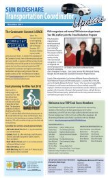
For the design <strong>of</strong> a bus bay, it is recommended that a minimum 6:1 bay taper be used to<br />
provide a twelve-foot minimum width bus bay. The bus bays should provide <strong>for</strong> 95-feet <strong>of</strong><br />
storage length, unless it is a layover location, and if necessary a 4:1 exit taper. Figure 5-4<br />
provides the bus bay details <strong>for</strong> two types <strong>of</strong> design.<br />
Page 29
<strong>Transportation</strong> <strong>Access</strong> <strong>Management</strong> <strong>Guidelines</strong> <strong>for</strong> the <strong>City</strong> <strong>of</strong> <strong>Tucson</strong><br />
Bus Bay Deta ils<br />
Detail #1<br />
(Major Intersections)<br />
DETAIL #2<br />
(Minor Intersection)<br />
Figure 5-4 Bus Bay Detail<br />
Page 30
<strong>Transportation</strong> <strong>Access</strong> <strong>Management</strong> <strong>Guidelines</strong> <strong>for</strong> the <strong>City</strong> <strong>of</strong> <strong>Tucson</strong><br />
6.0 Methods <strong>of</strong> Application<br />
6.1 Traffic Impact Analysis<br />
The <strong>City</strong> may request that a traffic impact Analysis (TIA) be prepared <strong>for</strong> proposed<br />
developments consistent with its policies. A detailed description <strong>of</strong> the methodology and<br />
necessary data is presented in Section 6.3.2.<br />
6.2 Variances<br />
Where the <strong>City</strong> <strong>of</strong> <strong>Tucson</strong> finds that extraordinary hardships or practical difficulties may<br />
result from strict compliance with approved requirements, the <strong>City</strong> may approve variations to<br />
the requirements, provided that safety standards are met, so that the public interest is served.<br />
The agency may require that a traffic impact analysis (TIA) or other in<strong>for</strong>mation or studies<br />
be submitted when reviewing a request <strong>for</strong> a variation. Variances may be necessary <strong>for</strong><br />
exceptions to turning restrictions or spacing standards where it can be demonstrated that no<br />
other reasonable options are available.<br />
Economic development factors may be considered <strong>for</strong> development projects that will bring<br />
new job opportunities into the area. However, safety standards should not be compromised<br />
<strong>for</strong> purely economic reasons.<br />
A petition <strong>for</strong> any variation should be submitted in writing to the <strong>City</strong> by the developer. The<br />
developer must prove that the variation will not be contrary to the public interest and that<br />
unavoidable practical difficulty or unnecessary hardship will result if not granted. The<br />
developer should establish and substantiate that the variation con<strong>for</strong>ms to the <strong>City</strong>’s<br />
requirements and standards.<br />
Care should be taken in issuing variances. No variation should be granted unless it is found<br />
that the following relevant requirements and conditions are satisfied. The <strong>City</strong> may grant<br />
variations whenever it is determined that all <strong>of</strong> the following criteria have been met:<br />
1) The granting <strong>of</strong> the variation should be in harmony with the general purpose and<br />
intent <strong>of</strong> the regulations and should not result in undue delay or congestion or be<br />
detrimental to the safety <strong>of</strong> the motoring public using the roadway.<br />
2) There should be pro<strong>of</strong> <strong>of</strong> unique or existing special circumstances or conditions<br />
where strict application <strong>of</strong> the provisions would deprive the developer <strong>of</strong><br />
reasonable access. Circumstances that would allow reasonable access by a road<br />
or street other than a primary roadway, circumstances where indirect or restricted<br />
access can be obtained, or circumstances where engineering or construction<br />
solutions can be applied to mitigate the condition should not be considered unique<br />
or special.<br />
3) There should be pro<strong>of</strong> <strong>of</strong> the need <strong>for</strong> the access and a clear documentation <strong>of</strong> the<br />
practical difficulty or unnecessary hardship. It is not sufficient to show that<br />
greater pr<strong>of</strong>it or economic gain would result if the variation were granted.<br />
Furthermore, the hardship or difficulty cannot be self-created or self-imposed; nor<br />
Page 31
<strong>Transportation</strong> <strong>Access</strong> <strong>Management</strong> <strong>Guidelines</strong> <strong>for</strong> the <strong>City</strong> <strong>of</strong> <strong>Tucson</strong><br />
can it be established on this basis by the owner who purchases with or without<br />
knowledge <strong>of</strong> the applicable provisions. The difficulty or hardship must result<br />
from strict application <strong>of</strong> the provision, and it should be suffered directly and<br />
solely by the owner or developer <strong>of</strong> the property in question.<br />
Upon receipt <strong>of</strong> relevant in<strong>for</strong>mation, facts and necessary data, the governmental agency<br />
should review the in<strong>for</strong>mation and render a decision in writing to the developer. Materials<br />
documenting the variance should be maintained in the agency’s permit files.<br />
6.3 Site Design<br />
This sub-section sets <strong>for</strong>th criteria <strong>for</strong> access control and traffic impact analyses, as they<br />
apply to individual developments.<br />
6.3.1 <strong>Access</strong> Control Typical access control requirements <strong>for</strong> arterials and<br />
collectors are provided as follows:<br />
1) No driveway access to an arterial street should be allowed <strong>for</strong> any<br />
residential lot. Driveway access to collectors from residential lots should<br />
be discouraged and approved on a case-by-case evaluation.<br />
2) No driveway access should be allowed within 300 feet <strong>of</strong> the nearest right<strong>of</strong>-way<br />
line <strong>of</strong> an intersecting street.<br />
3) Driveways giving direct access may be denied if alternate access is<br />
available.<br />
4) When necessary <strong>for</strong> the safe and efficient movement <strong>of</strong> traffic, access<br />
points may be required to be designed <strong>for</strong> right turns in and out only.<br />
5) When approved, or directed by the <strong>City</strong>’s representative, a driveway<br />
access design may be a "street type intersection" with curb returns.<br />
6.3.2 Traffic Impact Analysis A Traffic Impact Analysis (TIA) is a specialized<br />
study <strong>of</strong> the impacts that a certain type and size <strong>of</strong> development will have on the<br />
surrounding transportation system. A TIA is essential <strong>for</strong> many access management<br />
decisions, such as spacing <strong>of</strong> driveways, traffic control devices, and traffic safety<br />
issues. It is specifically concerned with the generation, distribution, and assignment<br />
<strong>of</strong> traffic to and from new development. A TIA should also be used as part <strong>of</strong> the site<br />
planning process, not merely justification <strong>of</strong> the site plan. The purpose <strong>of</strong> this subsection<br />
is to establish uni<strong>for</strong>m guidelines <strong>for</strong> when a TIA is required and how the<br />
study is to be conducted.<br />
6.3.2.1 Requirements A complete TIA should be per<strong>for</strong>med if any <strong>of</strong> the<br />
following situations are proposed:<br />
1) All new developments, or additions to existing developments, which<br />
are expected to generate more than 100 new peak-hour vehicle trips<br />
Page 32
<strong>Transportation</strong> <strong>Access</strong> <strong>Management</strong> <strong>Guidelines</strong> <strong>for</strong> the <strong>City</strong> <strong>of</strong> <strong>Tucson</strong><br />
(total in and out vehicular movements). The peak-hour will be<br />
determined by the <strong>City</strong>’s representative.<br />
2) In some cases, a development that generates less than 100 new peak<br />
hour trips may require a TIA if it affects local “problem” areas. These<br />
would include high accident locations, currently congested areas, or<br />
areas <strong>of</strong> critical local concern. These cases will be based on the <strong>City</strong><br />
representative’s judgment.<br />
3) All applications <strong>for</strong> rezoning or special exception (e.g. big box).<br />
4) All applications <strong>for</strong> annexation.<br />
5) Any change in the land use or density that will change the site traffic<br />
generation by more than 15 percent, where at least 100 new peak-hour<br />
trips are involved.<br />
6) Any change in the land use that will cause the directional distribution<br />
<strong>of</strong> site traffic to change by more than 20 percent.<br />
7) When the original TIA is more than 2 years old, access decisions are<br />
still outstanding, and changes in development have occurred in the site<br />
environs.<br />
8) When development agreements are necessary to determine “fair share”<br />
contributions to major roadway improvements.<br />
The specific analysis requirements, and level <strong>of</strong> detail, are determined by the<br />
following requirements.<br />
• CATEGORY I TIA -- Developments which generate from 100 up<br />
to 500 peak hour trips. The study horizon should be limited to the<br />
opening year <strong>of</strong> the development. The minimum study area should<br />
include site access drives and adjacent signalized intersections<br />
and/or major unsignalized street intersections.<br />
• CATEGORY II TIA -- Developments that generate from 500 up<br />
to 1,000-peak hour trips. The study horizon should include both<br />
the opening year <strong>of</strong> the development and five years after opening.<br />
The minimum study area should include the site access drives and<br />
all signalized intersections and/or major unsignalized street<br />
intersections within one-half mile <strong>of</strong> the development.<br />
• CATEGORY III TIA -- Developments that generate 1,000 or<br />
more peak hour trips. The study horizon should include the<br />
opening year <strong>of</strong> the development, five years after opening and ten<br />
years after opening. The minimum study area should include the<br />
site access drives and all signalized intersections and/or major<br />
unsignalized street intersections within one mile <strong>of</strong> the<br />
development.<br />
Page 33
<strong>Transportation</strong> <strong>Access</strong> <strong>Management</strong> <strong>Guidelines</strong> <strong>for</strong> the <strong>City</strong> <strong>of</strong> <strong>Tucson</strong><br />
6.3.2.2 Qualifications <strong>for</strong> Preparing Traffic Impact Analysis Documents.<br />
The TIA should be conducted and prepared under the direction <strong>of</strong> a<br />
Pr<strong>of</strong>essional Traffic Engineer. The subject engineer should have special<br />
training and experience in traffic engineering.<br />
6.3.2.3 Analysis Approach and Methods. The traffic study approach and<br />
methods should be guided by the following criteria.<br />
6.3.2.3.1 STUDY AREA. The minimum study area should be<br />
determined by project type and size in accordance with the criteria<br />
previously outlined. The extent <strong>of</strong> the study area may be either enlarged,<br />
or decreased, depending on special conditions as determined by the<br />
<strong>City</strong>’s representative.<br />
6.3.2.3.2 STUDY HORIZON YEARS. The study horizon years should<br />
be determined by project type and size, in accordance with the criteria<br />
previously outlined.<br />
6.3.2.3.3 ANALYSIS TIME PERIOD. Both the morning and<br />
afternoon weekday peak hours should be analyzed, unless the proposed<br />
project is expected to generate no trips, or a very low number <strong>of</strong> trips,<br />
during either the morning or evening peak periods. If this is the case, the<br />
requirement to analyze one or both <strong>of</strong> these periods may be waived by the<br />
<strong>City</strong>’s representative.<br />
Where the peak traffic hour in the study area occurs during a different<br />
time period than the normal morning or afternoon peak travel periods (<strong>for</strong><br />
example mid-day), or occurs on a weekend, or if the proposed project has<br />
unusual peaking characteristics, these additional peak hours should also<br />
be analyzed.<br />
6.3.2.3.4 SEASONAL ADJUSTMENTS. When directed by the <strong>City</strong>’s<br />
representative, the traffic volumes <strong>for</strong> the analysis hours should be<br />
adjusted <strong>for</strong> the peak season, in cases where seasonal traffic data is<br />
available.<br />
6.3.2.3.5 DATA COLLECTION REQUIREMENTS. All data should<br />
be collected in accordance with the latest edition <strong>of</strong> the ITE Manual <strong>of</strong><br />
Traffic Engineering Studies, or as directed by the <strong>City</strong> <strong>of</strong> <strong>Tucson</strong>’s<br />
Traffic Engineer.<br />
Page 34
<strong>Transportation</strong> <strong>Access</strong> <strong>Management</strong> <strong>Guidelines</strong> <strong>for</strong> the <strong>City</strong> <strong>of</strong> <strong>Tucson</strong><br />
6.3.2.3.5.1 Traffic volumes. Manual turning movement counts<br />
should be obtained <strong>for</strong> all existing cross-street intersections to be<br />
analyzed during the morning and afternoon peak periods. Turning<br />
movement counts may be required during other periods as directed<br />
by the <strong>City</strong>’s representative.<br />
6.3.2.3.5.2 Daily traffic volumes. The current and projected daily<br />
traffic volumes should be presented in the report. If available, daily<br />
count data from the <strong>City</strong> <strong>of</strong> <strong>Tucson</strong>, Pima County, or the Pima<br />
Association <strong>of</strong> Governments (PAG) may be used. Where daily<br />
count data is not available, mechanical counts will be required at<br />
locations agreed upon by the <strong>City</strong>’s representative.<br />
6.3.2.3.5.3 Accident data. Traffic accident data should be<br />
obtained <strong>for</strong> the most current three-year period available.<br />
6.3.2.3.5.4 Roadway and intersection geometrics. Roadway<br />
geometric in<strong>for</strong>mation should be obtained. This includes, but is not<br />
limited to, roadway width, number <strong>of</strong> lanes, turning lanes, vertical<br />
grade, and location <strong>of</strong> nearby driveways, pedestrian facilities, and<br />
lane configuration at intersections.<br />
6.3.2.3.5.5 Traffic control devices. The location and type <strong>of</strong><br />
traffic controls should be identified.<br />
6.3.2.3.5.6 Bicycle and pedestrian volumes. When directed by<br />
the <strong>City</strong> <strong>of</strong> <strong>Tucson</strong>’s Traffic Engineer, bicycle and pedestrian<br />
volumes should be collected.<br />
6.3.2.3.6 TRAFFIC VOLUME FORECASTS. Future traffic volumes<br />
should be estimated using in<strong>for</strong>mation from transportation models, or<br />
applying an annual growth rate to the base-line traffic volumes. The<br />
future traffic volumes should be representative <strong>of</strong> the horizon year <strong>for</strong><br />
project development. If the annual growth rate method is used, the <strong>City</strong>’s<br />
representative must give prior approval to the growth rate.<br />
In addition, any nearby proposed "on-line" development projects should<br />
be taken into consideration when <strong>for</strong>ecasting future traffic volumes. The<br />
increase in traffic from proposed "on-line" projects should be compared<br />
to the increase in traffic by applying an annual growth rate. This<br />
in<strong>for</strong>mation should be provided by the <strong>City</strong>’s representative.<br />
If modeling in<strong>for</strong>mation is unavailable, the greatest traffic increase from<br />
either the "on-line" developments, the application <strong>of</strong> an annual growth<br />
Page 35
<strong>Transportation</strong> <strong>Access</strong> <strong>Management</strong> <strong>Guidelines</strong> <strong>for</strong> the <strong>City</strong> <strong>of</strong> <strong>Tucson</strong><br />
rate, or a combination <strong>of</strong> an annual growth rate and "on-line"<br />
developments, should be used to <strong>for</strong>ecast the future traffic volumes.<br />
6.3.2.3.7 TRIP GENERATION. The latest edition <strong>of</strong> Institute <strong>of</strong><br />
<strong>Transportation</strong> Engineers (ITE) Trip Generation Handbook should be<br />
used <strong>for</strong> selecting trip generation rates. Other rates may be used with the<br />
approval <strong>of</strong> the <strong>City</strong>’s representative in cases where the ITE Trip<br />
Generation Handbook does not include trip rates <strong>for</strong> a specific land use<br />
category, or includes only limited data, or where local trip rates have<br />
been shown to differ from the ITE rates.<br />
Site traffic should be generated <strong>for</strong> daily, AM and PM peak hour periods.<br />
Adjustments made <strong>for</strong> "passer-by" and "mixed-use" traffic volumes<br />
should follow the methodology outlined in the latest edition <strong>of</strong> the ITE<br />
Trip Generation Handbook. A "passer-by" traffic volume discount <strong>for</strong><br />
commercial centers should not exceed twenty five percent unless<br />
approved by the <strong>City</strong>'s representative.<br />
A trip generation table should be prepared showing proposed land use,<br />
trip rates, and vehicle trips <strong>for</strong> daily and peak hour periods and<br />
appropriate traffic volume adjustments, if applicable.<br />
6.3.2.3.8 TRIP DISTRIBUTION AND ASSIGNMENT. Projected<br />
trips should be distributed and added to the projected non-site traffic on<br />
the roadways and intersections under study. The specific assumptions<br />
and data sources used in deriving trip distribution and assignment should<br />
be documented in the report and approved by the <strong>City</strong>’s representative.<br />
Category III TIA’s may require the use <strong>of</strong> a travel demand model based<br />
on direction from the <strong>City</strong>’s representative.<br />
The site-generated traffic should be assigned to the street network in the<br />
study area based on the approved trip distribution percentages. The site<br />
traffic should be combined with the <strong>for</strong>ecasted traffic volumes to show<br />
the total traffic conditions estimated at development completion. A<br />
"figure" will be required showing daily and peak period turning<br />
movement volumes <strong>for</strong> each traffic study intersection. In addition, a<br />
"figure" should be prepared showing the base-line volumes with sitegenerated<br />
traffic added to the street network. This "figure" will represent<br />
site specific traffic impacts to existing conditions.<br />
6.3.2.3.9 CAPACITY ANALYSIS. Level <strong>of</strong> service (LOS) should be<br />
computed <strong>for</strong> signalized and unsignalized intersections in accordance<br />
with the latest edition <strong>of</strong> the Highway Capacity Manual. The intersection<br />
Page 36
<strong>Transportation</strong> <strong>Access</strong> <strong>Management</strong> <strong>Guidelines</strong> <strong>for</strong> the <strong>City</strong> <strong>of</strong> <strong>Tucson</strong><br />
LOS should be calculated <strong>for</strong> each <strong>of</strong> the following conditions (if<br />
applicable):<br />
1) Existing peak hour traffic volumes ("figure" required).<br />
2) Existing peak hour traffic volumes including site-generated<br />
traffic ("figure" required).<br />
3) Future traffic volumes not including site traffic ("figure"<br />
required).<br />
4) Future traffic volumes including site traffic ("figure" required).<br />
5) LOS results <strong>for</strong> each traffic volume scenario ("table" required).<br />
The LOS table should include LOS results <strong>for</strong> AM and PM peak periods<br />
if applicable. The table should show LOS conditions with corresponding<br />
vehicle delays <strong>for</strong> signalized intersections, and LOS conditions <strong>for</strong> the<br />
critical movements at unsignalized intersections. For signalized<br />
intersections, the LOS conditions and average vehicle delay should be<br />
provided <strong>for</strong> each approach and the intersection as a whole.<br />
Unless otherwise directed by the <strong>City</strong>’s representative, the capacity<br />
analysis <strong>for</strong> existing signalized intersections should be conducted using<br />
the Highway Capacity Manual Operational Method <strong>for</strong> each study<br />
horizon year. When directed by the <strong>City</strong>’s representative, the capacity<br />
analysis should be conducted using the Planning Analysis Method.<br />
When the operational capacity analysis method is used <strong>for</strong> existing<br />
signalized intersections, it should include existing phasing, timing, splits,<br />
and cycle lengths during the peak hour periods when available from the<br />
<strong>City</strong>’s representative.<br />
For unsignalized intersections, the Highway Capacity Manual<br />
methodology should be used.<br />
If the new development is scheduled to be completed in phases, the TIA<br />
will, if directed by the <strong>City</strong>’s representative, include a LOS analysis <strong>for</strong><br />
each separate development phase in addition to the TIA <strong>for</strong> each horizon<br />
year. The incremental increases in site traffic from each phase should be<br />
included in the LOS analysis <strong>for</strong> each preceding year <strong>of</strong> development<br />
completion. A "figure" will be required <strong>for</strong> each horizon year <strong>of</strong> phased<br />
development.<br />
6.3.2.3.10 QUEUE ANALYSIS. If directed by the <strong>City</strong>’s<br />
representative, a queue analysis should be completed using the following<br />
methods outlined in Section 5.3.2.1 to determine appropriate storage<br />
lengths <strong>for</strong> right turn and left turn lanes into and out <strong>of</strong> the site.<br />
Page 37
<strong>Transportation</strong> <strong>Access</strong> <strong>Management</strong> <strong>Guidelines</strong> <strong>for</strong> the <strong>City</strong> <strong>of</strong> <strong>Tucson</strong><br />
6.3.2.3.11 TRAFFIC SIGNAL WARRANT ANALYSIS. A traffic<br />
signal warrant study should be conducted if directed by the <strong>City</strong>’s<br />
representative. The analysis will be required <strong>for</strong> each horizon year.<br />
Traffic signal warrant studies should be conducted by a method preapproved<br />
by the <strong>City</strong>’s representative.<br />
6.3.2.3.12 ACCIDENT ANALYSIS. If directed by the <strong>City</strong>’s<br />
representative, an analysis <strong>of</strong> three-year accident data should be<br />
conducted to determine the level <strong>of</strong> safety <strong>of</strong> the study area and any<br />
possible mitigation ef<strong>for</strong>ts.<br />
6.3.2.3.13 SPEED ANALYSIS. Vehicle speed is used to estimate safe<br />
stopping and cross corner sight distances. In general, the posted speed<br />
limit is representative <strong>of</strong> the 85th percentile speed and may be used to<br />
calculate safe stopping and cross corner sight distances. If directed by<br />
the <strong>City</strong>’s representative, speed counts should be taken in the study area.<br />
6.3.2.3.14 TRAFFIC SIMULATION. For a major development, a<br />
simulation using SYNCHRO or other approved s<strong>of</strong>tware should be done<br />
to show existing traffic flows and future traffic flows if directed by the<br />
<strong>City</strong>’s representative.<br />
6.3.2.3.15 MITIGATION REQUIREMENTS. The roadways and<br />
intersections within the study area should be analyzed, with and without<br />
the proposed development to identify any projected impacts in regard to<br />
level <strong>of</strong> service and safety.<br />
Where the roadway will not operate at Level <strong>of</strong> Service D or better with<br />
the development, the traffic impact <strong>of</strong> the development on the roadways<br />
and intersections within the study area shall be mitigated to Level <strong>of</strong><br />
Service D.<br />
6.3.2.3.16 INTER-AGENCY COORDINATION. When a new<br />
development falls within the boundaries <strong>of</strong> more than one government<br />
agency jurisdiction, the TIA should be distributed as an in<strong>for</strong>mational<br />
report to all affected agencies. The agency with governing powers over<br />
the development site will have final approval <strong>of</strong> the TIA.<br />
6.3.2.4 Report Format. This sub-section provides the <strong>for</strong>mat requirements <strong>for</strong><br />
the general text arrangement <strong>of</strong> a TIA. Deviations from this <strong>for</strong>mat must<br />
receive prior approval <strong>of</strong> the <strong>City</strong>’s representative.<br />
Page 38
<strong>Transportation</strong> <strong>Access</strong> <strong>Management</strong> <strong>Guidelines</strong> <strong>for</strong> the <strong>City</strong> <strong>of</strong> <strong>Tucson</strong><br />
6.3.2.4.1 TABLE OF CONTENTS<br />
6.3.2.4.2 TABLE OF FIGURES<br />
6.3.2.4.3 LIST OF TABLES<br />
6.3.2.4.4 EXECUTIVE SUMMARY<br />
Purpose <strong>of</strong> Report and Study Objectives<br />
Site Location and Study Area<br />
Development Description<br />
Principal Findings<br />
Conclusions<br />
6.3.2.4.5 PROJECT DESCRIPTION<br />
Site Location<br />
Land Use and Intensity<br />
Proposed Development Details<br />
Site Plan (readable version should be provided)<br />
<strong>Access</strong> Geometrics<br />
Development Phasing and Timing<br />
6.3.2.4.6 EXISTING CONDITIONS<br />
Study Area<br />
Roadway System<br />
Pedestrian/Bicycle Facilities<br />
Transit<br />
Sight Distance<br />
Existing Land Use<br />
6.3.2.4.7 EXISTING TRAFFIC DATA<br />
Traffic Counts<br />
Pedestrian Counts (if necessary)<br />
Bicycle Counts (if necessary)<br />
Times Collected<br />
Locations<br />
Types - Daily, Morning, and Afternoon Peak Periods<br />
(two hours minimum, and others as required)<br />
Page 39
<strong>Transportation</strong> <strong>Access</strong> <strong>Management</strong> <strong>Guidelines</strong> <strong>for</strong> the <strong>City</strong> <strong>of</strong> <strong>Tucson</strong><br />
6.3.2.4.8 TRIP GENERATION<br />
Trip Generation<br />
Pass-by Traffic (if applicable)<br />
6.3.2.4.9 TRIP DISTRIBUTION AND ASSIGNMENT<br />
Trip Distribution<br />
Trip Assignment<br />
6.3.2.4.10 ACCESS<br />
Site <strong>Access</strong><br />
Driveways<br />
6.3.2.4.11 ACCIDENT ANALYSIS<br />
Analysis Years<br />
Types <strong>of</strong> Accidents<br />
DUI<br />
Injury<br />
Non-injury<br />
Fatalities<br />
6.3.2.4.12 EXISTING TRAFFIC OPERATIONS<br />
Level <strong>of</strong> Service<br />
Morning Peak Hour, Afternoon Peak Hour<br />
(and others as required)<br />
6.3.2.4.13 FUTURE TRAFFIC OPERATIONS WITHOUT<br />
PROJECT<br />
Projections <strong>of</strong> non-site traffic (Methodology <strong>for</strong> projections<br />
should receive prior approval <strong>of</strong> <strong>City</strong>’s representative)<br />
Roadway Improvements<br />
Improvements Programmed to Accommodate Non-site<br />
Traffic<br />
Additional Alternative Improvements to Accommodate<br />
Site Traffic<br />
Level <strong>of</strong> Service Analysis Without Project (<strong>for</strong> each horizon<br />
year including any programmed improvements)<br />
6.3.2.4.14 TRAFFIC SIGNAL WARRANT ANALYSIS<br />
Warrant Analysis should be per<strong>for</strong>med <strong>for</strong> each horizon year<br />
with and without project (Methodology <strong>for</strong> analysis should<br />
receive prior approval <strong>of</strong> <strong>City</strong>’s representative)<br />
Page 40
<strong>Transportation</strong> <strong>Access</strong> <strong>Management</strong> <strong>Guidelines</strong> <strong>for</strong> the <strong>City</strong> <strong>of</strong> <strong>Tucson</strong><br />
6.3.2.4.15 FUTURE TRAFFIC OPERATIONS WITH PROJECT<br />
Level <strong>of</strong> Service Analysis With Project (<strong>for</strong> each horizon year,<br />
including any programmed improvements)<br />
6.3.2.4.16 SUGGESTED TRAFFIC MITIGATIONS<br />
Pedestrian/Bicycle Considerations<br />
Traffic Control Needs<br />
Intersection Channelization Mitigation<br />
Neighborhood Traffic Mitigation<br />
6.3.2.4.17 TURN LANE ANALYSIS<br />
Turn lane need<br />
Turn lane storage lengths<br />
6.3.2.4.18 CONCLUSION<br />
Trips Generated<br />
Trip Impacts<br />
Vehicular<br />
Pedestrian<br />
Bicycle<br />
Transit<br />
Recommendations<br />
Other<br />
6.3.2.4.19 APPENDICIES<br />
Traffic Volume Counts<br />
Capacity Analyses Worksheets<br />
Traffic Signal Warrant Analysis<br />
Accident Data and Summaries<br />
Miscellaneous Addendum<br />
6.4 Existing Problem Areas<br />
Introducing a “retr<strong>of</strong>it” program <strong>of</strong> access control to an existing roadway is <strong>of</strong>ten difficult.<br />
Land <strong>for</strong> needed improvements is <strong>of</strong>ten unavailable, making certain access management<br />
techniques impossible to implement and requiring the use <strong>of</strong> minimum rather than desirable<br />
standards. Rights <strong>of</strong> property access should be respected. Social and political pressures will<br />
emerge from abutting property owners who perceive that their access will be unduly<br />
restricted and their business hurt. The needed cooperation <strong>of</strong> proximate, sometimes<br />
competitive, developments in rationalizing on-site access and driveway locations may be<br />
difficult to achieve. And it may also be difficult to compare the cost <strong>of</strong> economic hardship to<br />
an individual to the benefits accruing to the general public. Accordingly, the legal, social,<br />
and political aspects <strong>of</strong> access management are particularly relevant in retr<strong>of</strong>it situations and<br />
Page 41
<strong>Transportation</strong> <strong>Access</strong> <strong>Management</strong> <strong>Guidelines</strong> <strong>for</strong> the <strong>City</strong> <strong>of</strong> <strong>Tucson</strong><br />
should be thoroughly understood by public agencies and private groups responsible <strong>for</strong><br />
implementing access control programs <strong>for</strong> retr<strong>of</strong>it projects.<br />
The general reasons underlying retr<strong>of</strong>it actions include the following:<br />
1) Increased congestion and accidents along a given section <strong>of</strong> road that are<br />
attributed to random or inadequate access;<br />
2) Major construction or design plans <strong>for</strong> a road that make access management and<br />
control essential;<br />
3) Street expansions or improvements that make it practical to reorient access to a<br />
cross street and remove (or reduce) arterial access; and<br />
4) Coordinating driveways, on one side <strong>of</strong> a street, with those planned by a<br />
development on the other side.<br />
6.4.1 Types <strong>of</strong> Action. Most retr<strong>of</strong>it actions involve the application <strong>of</strong> accepted<br />
traffic engineering techniques that limit the number <strong>of</strong> conflict points, separate basic<br />
conflict areas, limit speed adjustment problems, and remove turning vehicles from the<br />
through travel lanes. Tables 6-1 through 6-4 presents the various access management<br />
techniques that achieve each <strong>of</strong> these objectives and mainly apply to retr<strong>of</strong>it<br />
situations.<br />
Page 42
<strong>Transportation</strong> <strong>Access</strong> <strong>Management</strong> <strong>Guidelines</strong> <strong>for</strong> the <strong>City</strong> <strong>of</strong> <strong>Tucson</strong><br />
TABLE 6-1 1<br />
Retr<strong>of</strong>it Techniques – Category A<br />
CATEGORY A – Limit Number <strong>of</strong> Conflict Points<br />
No.<br />
Description<br />
A-1 Install median barrier with no direct left-turn access<br />
A-2 Install raised median divider with left-turn deceleration lanes<br />
A-3 Install one-way operations on the roadway<br />
A-4 Install traffic signal at high-volume driveways<br />
A-5 Channelize median openings to prevent left-turn ingress and/or egress maneuvers<br />
A-6 Widen right through lane to limit right-turn encroachment onto the adjacent lane to the<br />
left<br />
A-7 Install channelizing islands to prevent left-turn deceleration lane vehicles from returning<br />
to the through lanes<br />
A-8 Install physical barrier to prevent uncontrolled access along property frontages<br />
A-9 Install median channelization to control the merge <strong>of</strong> left-turn egress vehicles<br />
A-10 Offset opposing driveways<br />
A-11 Locate driveway opposite a three-leg intersection or driveway and install traffic signals<br />
where warranted<br />
A-12 Install two one-way driveways in lieu <strong>of</strong> one two-way driveway<br />
A-13 Install two two-way driveways with limited turns in lieu <strong>of</strong> one standard two-way<br />
driveway<br />
A-14 Install two one-way driveways in lieu <strong>of</strong> two two-way driveways<br />
A-15 Install two two-way driveways with limited turns in lieu <strong>of</strong> two standard two-way<br />
driveways<br />
A-16 Install driveway channelizing island to prevent left-turn maneuvers<br />
A-17 Install driveway channelizing island to prevent driveway encroachment conflicts<br />
A-18 Install channelizing island to prevent right-turn deceleration lane vehicles from returning<br />
to the through lanes<br />
A-19 Install channelizing island to control the merge area <strong>of</strong> right-turn egress vehicles<br />
A-20 Regulate the maximum width <strong>of</strong> driveways<br />
1 Adapted from: Federal Highway Administration. (1998)<br />
Page 43
<strong>Transportation</strong> <strong>Access</strong> <strong>Management</strong> <strong>Guidelines</strong> <strong>for</strong> the <strong>City</strong> <strong>of</strong> <strong>Tucson</strong><br />
TABLE 6-2 1<br />
Retr<strong>of</strong>it Techniques – Category B<br />
CATEGORY B – Separate Basic Conflict Areas<br />
No.<br />
Description<br />
B-1* Regulate minimum spacing <strong>of</strong> driveways<br />
B-2 Regulate minimum corner clearance<br />
B-3 Regulate minimum property clearance<br />
B-4* Optimize driveway spacing in the permit authorization stage<br />
B-5* Regulate maximum number <strong>of</strong> driveways per property frontage<br />
B-6 Consolidate access <strong>for</strong> adjacent properties<br />
B-7 Require roadway damages <strong>for</strong> extra driveways<br />
B-8 Purchase abutting properties<br />
B-9 Deny access to small frontage<br />
B-10 Consolidate existing access whenever separate parcels are assembled under one purpose,<br />
plan, entity, or usage<br />
B-11* Designate the number <strong>of</strong> driveways regardless <strong>of</strong> future subdivision <strong>of</strong> that property<br />
B-12 Require access on collector street (when available) in lieu <strong>of</strong> additional driveway on<br />
arterial<br />
* = not directly applicable <strong>for</strong> retr<strong>of</strong>it<br />
TABLE 6-3 1<br />
Retr<strong>of</strong>it Techniques – Category C<br />
CATEGORY C – Limit Speed-Adjustment Problems<br />
No.<br />
Description<br />
C-1 Install traffic signals to slow roadway speeds and meter traffic <strong>for</strong> larger gaps<br />
C-2 Restrict parking on the roadway next to driveways to increase driveway turning speeds<br />
C-3 Install visual cues <strong>of</strong> the driveway<br />
C-4 Improve driveway sight distance<br />
C-5 Regulate minimum sight distance<br />
C-6* Optimize sight distance in the permit authorization stage<br />
C-7 Increase the effective approach width <strong>of</strong> the driveway (horizontal geometrics)<br />
C-8 Improve the driveway pr<strong>of</strong>ile (vertical geometrics)<br />
C-9 Require driveway paving<br />
C-10 Regulate driveway construction (per<strong>for</strong>mance bond) and maintenance<br />
C-11 Install right-turn acceleration lane<br />
C-12 Install channelizing islands to prevent driveway vehicles from backing onto the arterial<br />
C-13 Install channelizing islands to move ingress merge point laterally away from the arterial<br />
C-14 Move sidewalk-driveway crossing laterally away from the arterial.<br />
* = not directly applicable <strong>for</strong> retr<strong>of</strong>it<br />
1 Adapted from: Federal Highway Administration. (1998)<br />
Page 44
<strong>Transportation</strong> <strong>Access</strong> <strong>Management</strong> <strong>Guidelines</strong> <strong>for</strong> the <strong>City</strong> <strong>of</strong> <strong>Tucson</strong><br />
TABLE 6-4 1<br />
Retr<strong>of</strong>it Techniques – Category D<br />
CATEGORY D – Remove Turning Vehicles from the Through Lanes<br />
No.<br />
Description<br />
D-1 Install two-way left-turn lane<br />
D-2 Install continuous left-turn lane<br />
D-3 Install alternating left-turn lane<br />
D-4 Install isolated median and deceleration lane to shadow and store left-turning vehicles<br />
D-5 Install left-turn deceleration lane in lieu <strong>of</strong> right-angle crossover<br />
D-6 Install median storage <strong>for</strong> left-turn egress vehicles<br />
D-7 Increase storage capacity <strong>of</strong> existing left-turn deceleration lane<br />
D-8 Increase the turning speed <strong>of</strong> right-angle median crossovers by increasing the effective<br />
approach width<br />
D-9 Install continuous right-turn lane<br />
D-10 Construct a local service road<br />
D-11* Construct a bypass road<br />
D-12* Reroute through traffic<br />
D-13 Install supplementary one-way right-turn driveways to divided roadway (non-capacity<br />
warrant)<br />
D-14 Install supplementary access on collector street when available (non-capacity warrant)<br />
D-15 Install additional driveway when total driveway demand exceeds capacity<br />
D-16 Install right-turn deceleration lane<br />
D-17 Install additional exit lane on driveway<br />
D-18 Encourage connections between adjacent properties (even when each has arterial access)<br />
D-19 Require two-way driveway operation where internal circulation is not available<br />
D-20 Require adequate internal design and circulation plan<br />
* = not directly applicable <strong>for</strong> retr<strong>of</strong>it<br />
1 Adapted from: Federal Highway Administration. (1998)<br />
Page 45
<strong>Transportation</strong> <strong>Access</strong> <strong>Management</strong> <strong>Guidelines</strong> <strong>for</strong> the <strong>City</strong> <strong>of</strong> <strong>Tucson</strong><br />
7.0 Guideline References<br />
(Effective January 2003)<br />
American Association <strong>of</strong> State Highway Officials (AASHO), Roadside Design Guide.<br />
Washington, DC: 1973.<br />
American Association <strong>of</strong> State Highway and <strong>Transportation</strong> Officials (AASHTO “Green<br />
Book”), A Policy on Geometric Design <strong>of</strong> Highways and Streets. Washington, DC:<br />
2001.<br />
American Public Works Association (Southern Utah Chapter), “Traffic Standards.” St.<br />
George, UT: 1996.<br />
<strong>City</strong> <strong>of</strong> Chandler, “Street Design and <strong>Access</strong> Control, Technical Design Manual #4.”<br />
Chandler, AZ: January 2002.<br />
<strong>City</strong> <strong>of</strong> Glendale, “Design <strong>Guidelines</strong> <strong>for</strong> Site Development and Infrastructure Construction.”<br />
Glendale, AZ: 1997.<br />
<strong>City</strong> <strong>of</strong> <strong>Tucson</strong>, “Development Standards, Section 3. <strong>Transportation</strong>.” <strong>Tucson</strong>, AZ. March<br />
1998.<br />
<strong>City</strong> <strong>of</strong> <strong>Tucson</strong>, <strong>Tucson</strong> <strong>City</strong> Code, Section 25-38 to 25-40. <strong>Tucson</strong>, AZ: October 1964.<br />
<strong>City</strong> <strong>of</strong> <strong>Tucson</strong> Department <strong>of</strong> <strong>Transportation</strong>, “Roadway Development Policies, Update to<br />
Ordinance 6593.” <strong>Tucson</strong>, AZ: April 1998.<br />
<strong>City</strong> <strong>of</strong> <strong>Tucson</strong> Planning Department, Major Streets & Routes Plan. <strong>Tucson</strong>, AZ: October<br />
1996.<br />
Federal Highway Administration, “<strong>Access</strong> <strong>Management</strong>, Location and Design.” National<br />
Highway Institute Course No. 15255, June 1998.<br />
Flora, John W., and Keitt, Kenneth M., <strong>Access</strong> <strong>Management</strong> <strong>for</strong> Streets and Highways.<br />
Washington, DC: Federal Highway Administration, FHWA IP-82-3, June 1982.<br />
Idaho <strong>Transportation</strong> Department, “Traffic Manual.”<br />
Institute <strong>of</strong> <strong>Transportation</strong> Engineers (ITE), Traffic Engineering Handbook – 5 th Edition,<br />
Washington, DC: 1999.<br />
Keopke, Frank J., and Levinson, H.S., <strong>Access</strong> <strong>Management</strong> <strong>Guidelines</strong> <strong>for</strong> Activity Centers.<br />
Washington, DC: <strong>Transportation</strong> Research Board, NCHRP Report 348, 1992.<br />
Koepke, Frank J., and Stover, Vergil G., <strong>Transportation</strong> and Land Development. Englewood<br />
Cliffs, NJ: Prentice Hall, 1988.<br />
Pima County Department <strong>of</strong> <strong>Transportation</strong> and Flood Control, “Roadway Design Manual –<br />
1 st Edition.” Pima County, AZ, September 1998.<br />
Page 46
<strong>Transportation</strong> <strong>Access</strong> <strong>Management</strong> <strong>Guidelines</strong> <strong>for</strong> the <strong>City</strong> <strong>of</strong> <strong>Tucson</strong><br />
Ronald K. Giguere, TRB Chair. Driveway and Street Intersection Spacing. <strong>Transportation</strong><br />
Research Board (TRB), <strong>Transportation</strong> Research Circular 456. Washington, DC,<br />
March 1996.<br />
<strong>Transportation</strong> Research Board. Conference Proceedings <strong>of</strong> the Second National Conference<br />
on <strong>Access</strong> <strong>Management</strong> (Held in Vail, CO, August 11-14, 1996). Washington, DC:<br />
U.S. Department <strong>of</strong> <strong>Transportation</strong>, 1996.<br />
<strong>Transportation</strong> Research Board - National Research Council, Highway Capacity Manual<br />
(HCM). Washington, DC, 2000 Fourth edition.<br />
U.S. Department <strong>of</strong> <strong>Transportation</strong> – Federal Highway Administration, Manual on Uni<strong>for</strong>m<br />
Traffic Control Devices <strong>for</strong> Streets and Highways (MUTCD). Washington, DC:<br />
1988.<br />
Wasatch Front Regional Council, “<strong>Access</strong> <strong>Management</strong> Techniques <strong>for</strong> Local<br />
Governments.” Bountiful, UT, Report No. 56, July 1991.<br />
Page 47