SF-1700 Bicep/Tricep - Paramount Fitness
SF-1700 Bicep/Tricep - Paramount Fitness
SF-1700 Bicep/Tricep - Paramount Fitness

You also want an ePaper? Increase the reach of your titles
YUMPU automatically turns print PDFs into web optimized ePapers that Google loves.
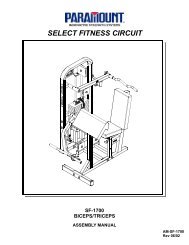
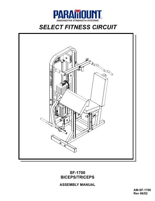
SELECT FITNESS CIRCUIT<br />
<strong>SF</strong>-<strong>1700</strong><br />
BICEPS/TRICEPS<br />
ASSEMBLY MANUAL<br />
AM-<strong>SF</strong>-<strong>1700</strong><br />
Rev 06/02
SAFETY<br />
1. Review and understand all of the warning labels affixed to the machines and the<br />
facility safety sign. Replace any warning label at first sign of wear. Labels and the Facility<br />
Safety Sign may be obtained from <strong>Paramount</strong> free of charge.<br />
2. Be certain that machine operation is understood before machine is used. Refer to<br />
the instruction label provided with the machine.<br />
3. Keep children away from this equipment.<br />
4. DO NOT high-pin or double-pin the weight stack. DO NOT allow the machine to be<br />
used if the top plate or weight stack is pinned in a raised position. Use an assistant and<br />
carefully return the machine to the proper position with the cap plate resting on the top<br />
weight. Inspect the cable to ensure that it is seated in all of the pulleys.<br />
5. Use ONLY <strong>Paramount</strong> weight selector pins. Other manufacturer’s pins may work<br />
free of the weight stack causing possible injury. Be certain the pin is completely<br />
inserted prior to use.<br />
6. Cables: Check the entire length of the cable weekly. Pay close attention to the area<br />
going over pulleys and to the end connections. Inspect the cable end fittings daily. When<br />
adjusting cables at threaded inserts make sure all connections are tight. Adjust tension<br />
on cables as needed. Replace all cables at first signs of wear. Use only <strong>Paramount</strong><br />
supplied replacement cables. Ensure that the dimension from under the bolt head to<br />
the top surface of the selector bar is no greater than 1-3/8 inches (see installation).<br />
Ensure that the cable tension bolt & nut are tight.<br />
7. Nuts, Bolts, and Fasteners: Check tightness weekly. If any hardware has become<br />
loose, retighten and/or use Loctite Threadlocker 242.<br />
8. Frames and Lifting Arms: Inspect weekly for integrity and function. Replace any<br />
component at first signs of wear.<br />
9. DO NOT attempt to free any jammed assemblies by yourself as this may cause injury.<br />
10. Use ONLY <strong>Paramount</strong> adder weights or adder weight systems for incremental<br />
resistance adjustment. NEVER use dumbbells or other means to do this.<br />
11. Instruct Users not to wear loose or dangling clothes or have headphone wire hanging<br />
when using this equipment.<br />
12. Recommend that users receive a medical exam before commencing an exercise<br />
program. User should stop exercising if they feel faint or dizzy.<br />
13. Check regularly the functionality of your machine by verifying the following:<br />
• cables and end fittings are intact and tensioned properly,<br />
• all adjustments are possible and carried out with ease,<br />
• the proper selector pin is in the weight stack,<br />
• the exercise is performed smoothly, free of noise and/or binding,<br />
• and the guide rods and linear bearings are properly lubricated.<br />
14. Follow the installation guidelines provided with the products.<br />
15. Retain these instructions for future reference.<br />
If you have any questions, do not hesitate to contact your <strong>Paramount</strong> dealer or <strong>Paramount</strong><br />
<strong>Fitness</strong> Corp. at (800)721-2121 or www.paramountfitness.com.<br />
Refer to Maintenance Schedule label on machine for when to schedule maintenance.<br />
1
MAINTENANCE<br />
1. Frames: Wipe all machines down with a damp cloth and dry completely each day. This includes painted,<br />
chrome parts and upholstered pads.<br />
2. Painted/chrome parts: Use Simple Green or similar cleaner for light dirt and grime. Use TurtleWax®<br />
Polishing Compound or a good car polish to remove heavier dirt and grease as well as for polishing. DO<br />
NOT use solvents, lacquer thinner, acetone or finger nail polish remover. For scuffs and marks that are not<br />
removed by the above methods use a soft scrub cleanser.<br />
3. Upholstery: Use cloth towels and warm water daily to remove surface dirt and perspiration. Use a lanolin<br />
based hand cleaner or Naugahyde® brand upholstery cleaner to condition and deep clean on a weekly<br />
basis. DO NOT use Windex, Simple Green, 409, or similar products to clean the upholstery.<br />
4. Weight stack enclosures (shrouds): Wipe down with a damp cloth as needed.<br />
5. Exercise instruction labels: Clean with soap and water as needed.<br />
6. Linear bearing shafts: Wipe down linear rails using a light application of Magnalube® lubricant or a<br />
similar teflon grease on a weekly basis to remove dust, hair, and dirt. Polish the shaft using fine sandpaper<br />
or steel wool if light rust is present.<br />
7. Guide rods: Wipe all dirt and dust off the guide rods before applying a light application of Tri-Flow TM or<br />
other silicone spray lubricant, spraying the Tri-Flow TM on a rag and then wiping the guide rods with the rag.<br />
DO NOT use oil base lubricants such as WD-40. Caution: Tri-Flow TM will stain carpet and clothing.<br />
8. Bronze bushings: Check monthly for signs of wear and replace as needed. Lubricate monthly with Tri-<br />
Flow TM .<br />
9. Seat adjustments: Clean the chrome seat adjustment tube on a weekly basis using a rag sprayed with<br />
Tri-Flow TM . Keep a light layer of Tri-Flow TM on these tubes at all times.<br />
We recommend that you purchase the <strong>Paramount</strong> Performance Kit (P/N KIT-01) to maintain your <strong>Paramount</strong><br />
products. This will insure that the proper maintenance materials required will be used. Please refer<br />
to the General Maintenance Manual (p/n AM-GMM) for other important safety and maintenance information.<br />
ASSEMBLY NOTES<br />
1) It is recommended that two (2) people be used to assemble this machine.<br />
2) Assemble this machine on a solid level surface. Read the assembly instructions completely before<br />
beginning to assemble the machine. This will help you to become familiar with the machine and prevent<br />
mistakes requiring unnecessary disassembly and reassembly.<br />
3) Hardware placement is indicated as A , etc. Refer to the hardware page for corresponding size and<br />
configuration. You will have some remaining hardware as extra pieces are always included in one of<br />
the bags.<br />
4) Install all plastic end caps on assemblies where necessary before assembling the machine.<br />
5) Initially tighten all hardware by hand, as this will assist in the alignment of the machine. When the<br />
framework of the machine is complete, tighten all nuts, bolts and setscrews. Be sure all hardware is<br />
tight before using the machine. Recheck all hardware upon completion of the assembly process.<br />
6) Hex- and Sockethead bolt length is measured from the bottom of the head to the end of the bolt.<br />
Length of Flathead bolts is measured as the total overall length.<br />
7) Bolts should point inward on the machine wherever possible, leaving the bolt heads facing out.<br />
8) Route cables prior to installing pulley wheels. Verify that the cables are seated in the pulleys prior to<br />
using the equipment.<br />
9) Read and understand all machine warning and instruction labels before using the machine.<br />
2
TOOLS REQUIRED:<br />
RUBBER<br />
MALLET<br />
SOCKET<br />
WRENCH<br />
PUNCH<br />
7/16” (11mm)<br />
WRENCH<br />
7/16” (11mm)<br />
9/16” (14mm)<br />
3/4” (19mm)<br />
7/8” (22mm)<br />
15/16” (24mm)<br />
ALLEN WRENCH<br />
5/32” (4mm)<br />
3/16” (5mm)<br />
SOCKET<br />
7/16” (11mm)<br />
9/16” (14mm)<br />
3/4” (19mm)<br />
<strong>SF</strong>-<strong>1700</strong>CTN1:<br />
1701515<br />
9000801X (2)<br />
8001525<br />
9099780X<br />
1701510X<br />
1701565X<br />
0101599<br />
0101520X<br />
8001520X<br />
1701570X<br />
1701591<br />
3
<strong>SF</strong>-<strong>1700</strong>CTN2:<br />
8093040<br />
1701545X<br />
1701540X<br />
1701520X<br />
1701560<br />
1701529 1701531<br />
1701550X<br />
2299HND001<br />
45 5/8” (116 cm)<br />
4000PLY000<br />
1701505<br />
1701600<br />
138 3/4” (352 cm)<br />
1701610<br />
HW-1701-1<br />
8093006X<br />
HW-1701-2<br />
HW-1701-3<br />
4
HARDWARE BAG 1701-2:<br />
B1295 (2)<br />
B 582 (2) B 682 (6)<br />
B 1136 (5)<br />
B 447<br />
B 898 B 900 (3) B 921 (6)<br />
B 1182 (2)<br />
B1117 (2)<br />
B 460<br />
HARDWARE BAG 1701-1:<br />
A B D G H<br />
3/8-16 x 1 1/4 HHCS<br />
3/8 Metal Base<br />
3/8 Lock Washer<br />
3/8 Black Washer<br />
Plastic Cover for 3/8<br />
I<br />
L<br />
3/8-16 x 1 BHCS<br />
3/8 Black Washer<br />
3/8-16 Locknut<br />
3/8 Metal Base<br />
Plastic Cover for 3/8<br />
3/8-16 x 2 3/4 HHCS<br />
3/8 Black Washer (2)<br />
3/8-16 Locknut<br />
3/8 Metal Base (2)<br />
Plastic Cover for 3/8 (2)<br />
3/8-16 X 3 3/4 HHCS<br />
3/8-16 Locknut<br />
3/8 Black Washer (2)<br />
3/8 Metal Base (2)<br />
Plastic Cover for 3/8 (2)<br />
3/8-16 x 4 HHCS<br />
3/8 Black Washer (2)<br />
3/8-16 Locknut<br />
Plastic Cover for 3/8 (2)<br />
3/8 Metal Base (2)<br />
N<br />
S<br />
3/8-16 x 2 1/4 HHCS<br />
3/8 Metal Base (2)<br />
3/8-16 Locknut<br />
3/8 Washer (2)<br />
Plastic Cover for 3/8 (2)<br />
3/8-16 x 1 3/4 HHCS<br />
3/8-16 Locknut<br />
3/8 Black Washer (2)<br />
3/8 Metal Base (2)<br />
Plastic Cover for 3/8(2)<br />
3/8-16 x 2 HHCS<br />
3/8 Metal Base<br />
3/8 Split Lockwasher<br />
3/8 Washer<br />
Plastic Cover for 3/8<br />
3/8-16 x 4 HHCS<br />
3/8 Split Lockwasher<br />
3/8 Washer<br />
3/8 Metal Base<br />
Plastic Cover<br />
D 836<br />
2 x 1 1/4 x 11/16<br />
Black Collar<br />
D 875<br />
7/16 x 2<br />
Roll Pin (2)<br />
C 757<br />
1” USS Flat<br />
Washer (2)<br />
C 955A<br />
3/8” Metal<br />
Base (2)<br />
C 955<br />
3/8” Plastic<br />
Cover (2)<br />
C 754B<br />
3/8<br />
Washer (2)<br />
C 628<br />
3/8-16 x 2 1/4<br />
SHCS<br />
D 588<br />
1.003 x 1.504<br />
x 1/8 Bearing (2)<br />
D 707<br />
9/16” I.D.<br />
Bumper w/Washer<br />
D 706<br />
1 1/2 Rubber<br />
Bumper<br />
C 732<br />
3/8-16 Hex<br />
Nut<br />
C 747<br />
1/4” Split<br />
Lockwasher (2)<br />
C 766A<br />
3/8-16 Locknut<br />
Nut (2)<br />
C 658<br />
3/8-16 x 1<br />
FHCS (2)<br />
C 752<br />
1/4” Flat<br />
Washer (4)<br />
C 653<br />
5/16-18 x 1<br />
FHCS<br />
C 675C<br />
1/4-20 x 1 BHCS (2)<br />
D 591<br />
1 1/4 x 1 11/16<br />
x 1/8 Thrust-<br />
Bearing (3)<br />
D 825A<br />
7/8 x 3/8 x 3/8<br />
Split Collar<br />
D 840<br />
1 3/4 x 1 x 1/2<br />
Split Collar<br />
D1041<br />
3/8 X 1<br />
Spacer<br />
5
MINIMUM FLOOR AREA REQUIRED:<br />
56”<br />
(142cm)<br />
92”<br />
(234cm)<br />
IN USE<br />
MACHINE WEIGHT (NOT INCLUDING<br />
WEIGHT OF USER):<br />
W/170 LB STACK 443 LBS<br />
W/250 LB STACK 523 LBS<br />
SHROUD OPTION +30LB<br />
47” (119cm)<br />
Height = 60 inches (152cm)<br />
83” (211cm)<br />
IN USE<br />
NOTE: THIS MACHINE IS DESIGNED FOR<br />
USERS WEIGHING 300LB OR LESS<br />
HARDWARE MEASUREMENT GUIDE:<br />
BHCS - BUTTON HEAD CAP SCREW<br />
SHCS - SOCKET HEAD CAP SCREW<br />
FHCS - FLAT HEAD CAP SCREW<br />
HHCS - HEX HEAD CAP SCREW<br />
1 2 3 4 5<br />
MEASURE BOLT<br />
FROM HERE<br />
6
TOP VIEW<br />
1<br />
Pulley Housing<br />
1701510X<br />
8093040<br />
1701515<br />
H (2)<br />
1701520X<br />
D (2)<br />
NOTE: WHEN INSTALLING HARDWARE, TIGHTEN BY<br />
HAND ONLY UNTIL ALL COMPONENTS ARE ASSEM-<br />
BLED. BOLT HEADS SHOULD FACE TO OUTSIDE OF<br />
MACHINE WHERE POSSIBLE. BE SURE ALL HARDWARE<br />
IS TIGHT BEFORE USING MACHINE. 7
2<br />
See<br />
Diagram A<br />
D<br />
1701545X<br />
See<br />
Diagram B<br />
I<br />
1701540X<br />
8093006X<br />
D 707 (2)<br />
C 747 (2)<br />
C 675C (2)<br />
C 752 (2)<br />
D<br />
D 875 D 591<br />
D 591<br />
Diagram A<br />
(ADD ADDITIONAL THRUST<br />
BEARING IF REQUIRED)<br />
1701531<br />
5 13/16”<br />
Align Holes!<br />
Diagram B<br />
1701570x<br />
D 840<br />
8
3<br />
See<br />
Diagram C<br />
G (2)<br />
1701560<br />
1701550X<br />
See Diagram D<br />
2299HND001<br />
D 836<br />
D 875<br />
Align Holes!<br />
Diagram C<br />
1701529<br />
C 628<br />
D1041<br />
C 732<br />
C 653<br />
Diagram D<br />
D 588<br />
(To fill gap<br />
if required)<br />
D 706<br />
9
4<br />
S (2)<br />
8001520X<br />
8001525<br />
0101599<br />
N (2)<br />
0101520X<br />
B1295 (2)<br />
5<br />
1701565X<br />
A (2)<br />
C 658 (2)<br />
1701591<br />
C 754B (4)<br />
C 955A (2)<br />
C 766A (2)<br />
C 955 (2)<br />
10
WEIGHT STACK INSTALLATION<br />
Review the equipment order to determine<br />
the weight stack configuration. The<br />
boxes are marked with the quantity and<br />
weight of the plates.<br />
P/N: B1602<br />
Comprised of<br />
(4) EACH 10lb MACHINED WEIGHT PLATES<br />
or<br />
P/N: B1603<br />
Comprised of<br />
(4) EACH 15lb MACHINED WEIGHT PLATES<br />
170lb<br />
16 x 10lb plates<br />
Qty (4) Box B1602<br />
250lb<br />
16 x 15lb plates<br />
Qty (4) Box B1603<br />
6<br />
9000801X (2)<br />
9099780X<br />
WEIGHT PLATES<br />
C 757 (2)<br />
B 582 (2)<br />
1701505<br />
NOTE: IF INSTALLING THE WEIGHT SHROUD<br />
OPTION REFER TO THE INSTALLATION<br />
INSTRUCTIONS PROVIDED WITH THE OPTION.<br />
11
7<br />
NOTE: TIGHTEN<br />
HARDWARE BY HAND<br />
ONLY AT THIS POINT.<br />
B (2)<br />
B 447<br />
8<br />
9099780X<br />
NOTE: MOVE CAP PLATE 9099780X UP TO PULLEY HOUSING TO<br />
SET THE CORRECT GUIDE ROD AND BRACKET SPACING. NOW<br />
COMPLETELY TIGHTEN HARDWARE. CAP PLATE SHOULD<br />
MOVE SMOOTHLY ALONG GUIDE RODS. IF NOT, LOOSEN HARD-<br />
WARE AND RESET SPACING.<br />
12
9<br />
B 898<br />
L<br />
1701600<br />
1701600<br />
MAX!<br />
1 3/8” (35mm)<br />
4000PLY000<br />
1701600<br />
MAX!<br />
MAKE SURE<br />
LOCKING NUT<br />
IS SECURE!<br />
1 3/8” (35mm)<br />
B 460<br />
NOTE: PARAMOUNT SELECTOR PIN B 460 IS<br />
THE ONLY PIN THAT SHOULD BE USED WITH<br />
THIS MACHINE. UNDER NO CIRCUMSTANCES<br />
SHOULD THE CAP PLATE OR WEIGHT STACK<br />
BE PINNED IN AN ELEVATED POSITION.<br />
13
10<br />
See<br />
Diagram F<br />
B 900 (3)<br />
L (3)<br />
1701610<br />
See<br />
Diagram E<br />
Diagram E<br />
Diagram F<br />
L<br />
1701610<br />
D 825A<br />
1701610<br />
14
SELECT FITNESS<br />
WEIGHT STACK LABELS<br />
Hardware Bag 1701-3 is packed with a weight stack number label set. Follow the<br />
instructions printed on the label. Below is a list of weight stacks and the corresponding<br />
label set part numbers:<br />
To install weight stack labels:<br />
Wt. Stack 170lb 250lb<br />
Part No. B2170 B2172<br />
1. Verify weights are installed properly.<br />
2. Wipe front surface of the weights with rubbing alcohol and allow to dry completely.<br />
3. Remove the backing from the labels. Align the top edge of the label with the top edge of the weights<br />
and the side of the label with the outside edge of the pin hole in the weights.<br />
4. Verify that the label strip is straight and then remove the liner. As the liner comes off the labels, press<br />
and rub each label into place.<br />
5. The adhesive requires 48 hours to cure so DO NOT attempt to “test” the integrity of the labels after they<br />
have been installed.<br />
Take the time during installation to align the label with the edge of the pin hole and the<br />
top surface of the weights to get all of the individual labels straight.<br />
Individual<br />
labels<br />
Liner<br />
Align with outside<br />
edge of pin holes<br />
15
WARNING LABELS<br />
The following warning labels are affixed to the <strong>SF</strong>-<strong>1700</strong>. Be certain that you and the<br />
facility staff are aware of the meaning and importance of each label. If the labels become<br />
damaged, replacements can be ordered free of charge from <strong>Paramount</strong>.<br />
!<br />
WARNING<br />
SERIOUS INJURY CAN OCCUR. KEEP YOUR HANDS<br />
CLEAR OF THIS AREA DURING USE OF THE MACHINE.<br />
P/N B2316 6/96<br />
ASTM Fxxx<br />
!<br />
WARNING<br />
SERIOUS INJURY CAN OCCUR ON THIS EQUIPMENT IF<br />
THE PIN IS NOT COMPLETELY INSERTED BEFORE USE.<br />
P/N B2065 11/96<br />
ASTM Fxxx<br />
!<br />
B2316<br />
B2065<br />
WARNING<br />
STABILIZING FOOT MUST BE ATTACHED HERE.<br />
P/N B2017<br />
!<br />
B2017<br />
WARNING<br />
SERIOUS INJURY CAN OCCUR<br />
ON THIS EQUIPMENT IF THE<br />
CABLES AND THEIR ATTACH-<br />
MENT COMPONENTS ARE NOT<br />
INSPECTED OFTEN. REPLACE<br />
AT FIRST SIGNS OF WEAR.<br />
P/N B2051 6/96<br />
ASTM Fxxx<br />
B2051<br />
!<br />
ASTM Fxxx<br />
WARNING<br />
1. MAKE SURE selector pin is inserted<br />
completely. Use only the <strong>Paramount</strong> pin shown<br />
2. Bolt height must not exceed 1 3/8”. Check<br />
regularly. Make sure locking nut is tight.<br />
ASTM F1749<br />
P/N B2141<br />
MAINTENANCE<br />
SCHEDULE<br />
Check the integrity and function<br />
of the following items. Replace<br />
all worn components immediately.<br />
Cables - Check tension, end<br />
fittings, and coating<br />
Check weight stack<br />
locking nut<br />
Upholstery - Wipe down and dry<br />
Clean and condition<br />
Frame - Wipe down and dry<br />
Polish/Wax<br />
Chrome - Wipe down and dry<br />
Polish/Wax<br />
Nuts/Bolts/Fasteners - Tighten<br />
and/or adjust as needed<br />
Guide Rods - Lubricate and clean<br />
Linear Rods - Lubricate and clean<br />
Seat Sleeves- Lubricate and clean<br />
Adjustments/Locking Pins/<br />
Tightening Knobs<br />
Weight Stack Pin<br />
Warning/Instruction Labels<br />
Springs<br />
Anti-Skid<br />
Hand Grips<br />
D<br />
A<br />
I<br />
L<br />
Y<br />
4<br />
4<br />
P/N B2315 5/98<br />
W<br />
EEKLY<br />
4<br />
4<br />
4<br />
4<br />
4<br />
4<br />
4<br />
Order <strong>Paramount</strong> Service Kit P/N KIT-01<br />
for recommended maintenance products<br />
PARAMOUNT CUSTOMER SERVICE<br />
1-800-721-2121<br />
PIN<br />
B2315<br />
MAXIMUM Height<br />
under Nut to<br />
Bolt head<br />
MAX<br />
1 3/8”<br />
5” Head to Ball<br />
<strong>Paramount</strong> Pin P/n B 460<br />
4<br />
4<br />
4<br />
4<br />
4<br />
4<br />
4<br />
4<br />
4<br />
!<br />
WARNING<br />
SERIOUS INJURY CAN OCCUR ON<br />
THIS EQUIPMENT. FOLLOW THESE<br />
PRECAUTIONS TO HELP AVOID INJURY.<br />
1. BEFORE USING: Read all of the<br />
warnings and obtain instruction on<br />
the use of this machine. Use only for<br />
the intended exercise. DO NOT<br />
modify the machine.<br />
2. Get a medical exam before<br />
beginning an exercise program.<br />
3. Keep body and clothing clear of all<br />
moving parts. DO NOT wear anything<br />
loose or dangling.<br />
4. Inspect the machine before use.<br />
DO NOT use it if it appears damaged.<br />
DO NOT try to fix any machine.<br />
Notify staff immediately.<br />
5. INSPECT MACHINE DAILY for<br />
loose, worn or damaged parts.<br />
Tighten and adjust all loose parts.<br />
Replace any part or label at first<br />
signs of wear. Inspect all cables and<br />
their connections closely. If you are<br />
in doubt about any part, DO NOT<br />
use the machine until the part is<br />
replaced.<br />
6. Inspect cables and connections<br />
before using the machine. DO NOT<br />
use this machine if any part appears<br />
worn or damaged.<br />
7. Be certain that weight pin B1003 is<br />
completely inserted. Use only the pin<br />
provided by the manufacturer. If<br />
unsure, seek assistance.<br />
8. NEVER pin the weights or top plate<br />
into an elevated position. DO NOT<br />
use the machine if found in this<br />
condition. DO NOT try to fix. Seek<br />
assistance.<br />
9. Use only the incremental weights<br />
supplied by the manufacturer. DO<br />
NOT use dumbbells or other means<br />
to add resistance to the machine.<br />
10. NEVER allow children near this<br />
machine. Supervise teenagers.<br />
11. DO NOT REMOVE THIS LABEL.<br />
REPLACE IF DAMAGED.<br />
P/N B2060 1/98<br />
B2060<br />
ASTM F1749<br />
B2141<br />
16
PARAMOUNT’s Limited Warranty<br />
<strong>Paramount</strong> warrants to the original purchaser from a <strong>Paramount</strong> authorized dealer that <strong>Paramount</strong><br />
equipment will be free from defects in material and workmanship under normal use and<br />
service for the following periods and in the following respects:<br />
LIFETIME WARRANTY Welds, Weight Plates, and Guide Rods<br />
FIVE YEAR WARRANTY Bronze Bushings, Sealed Rotating Bearings and Pulley Wheels<br />
ONE YEAR WARRANTY Cables, Linear Bearings, Linear Shafts and all other components<br />
not mentioned elsewhere in this warranty<br />
90-DAY WARRANTY Upholstery and Grips<br />
This limited warranty DOES NOT cover and no warranty is given with respect to:<br />
‚ Products not manufactured by <strong>Paramount</strong><br />
‚ Products which are altered without the express written consent of <strong>Paramount</strong><br />
‚ Products purchased other than directly from <strong>Paramount</strong> or through a <strong>Paramount</strong> authorized<br />
dealer.<br />
All warranty periods begin to run from the date of delivery to the original purchaser. The obligation<br />
of <strong>Paramount</strong> under this warranty is limited to repairing or replacing warranted defective<br />
parts, as <strong>Paramount</strong> may elect, at <strong>Paramount</strong>’s plant in Los Angeles, California, without charge to<br />
purchaser for either parts or labor. Purchaser is responsible for all transportation and insurance<br />
costs of returned or replaced equipment to and from <strong>Paramount</strong>’s plant in Los Angeles.<br />
ANY IMPLIED WARRANTY, INCLUDING BUT NOT LIMITED TO THE IMPLIED WAR-<br />
RANTY OF FITNESS FOR A PARTICULAR PURPOSE AND THE IMPLIED WARRANTY OF<br />
MERCHANTABILITY, IS LIMITED TO THE ONE YEAR DURATION FROM THE DATE OF DELIV-<br />
ERY TO THE ORIGINAL PURCHASER. SOME STATES DO NOT ALLOW LIMITATIONS ON<br />
HOW LONG AN IMPLIED WARRANTY LASTS, SO THE ABOVE LIMITATION MAY NOT APPLY<br />
TO YOU. THE REMEDY OF REPAIR AND REPLACEMENT IS THE EXCLUSIVE AND SOLE<br />
REMEDY OF THE PUCHASER. PARAMOUNT SHALL NOT BE LIABLE FOR ANY SPECIAL,<br />
INCIDENTAL, CONTINGENT OR CONSEQUENTIAL DAMAGES OF ANY KIND, INCLUDING,<br />
BUT NOT LIMITED TO, DAMAGE OR LOSS OF OTHER PROPERTY OR EQUIPMENT AND<br />
LOST PROFITS OR REVENUE. SOME STATES DO NOT ALLOW THE EXCLUSION OR LIMI-<br />
TATION OF INCIDENTAL OR CONSEQUENTIAL DAMAGES SO THE ABOVE LIMITATION OR<br />
EXCLUSION MAY NOT APPLY TO YOU.<br />
No action for breach of this written limited warranty or any implied warranty shall be commenced<br />
more than one year after the accrual of the cause of action. This written limited warranty<br />
is the complete, final and exclusive agreement of the parties with respect to the quality or performance<br />
of the goods and any and all warranties and representations. No modification of this limited<br />
warranty or waiver of its terms shall be binding on either party unless approved in writing by<br />
an authorized corporate officer of <strong>Paramount</strong>. This limited warranty gives you specific legal rights,<br />
and you may also have other rights which vary from state to state. Contact <strong>Paramount</strong> <strong>Fitness</strong><br />
Corp., 6450 E. Bandini Blvd., Los Angeles, California 90040-3185, before returning any defective<br />
equipment. <strong>Paramount</strong> <strong>Fitness</strong> Corp. © 1999. <strong>Paramount</strong> <strong>Fitness</strong> Corp. © 1993, 1995, 1997<br />
For More Information On Other <strong>Paramount</strong> Products:<br />
Advanced Performance Systems<br />
Select <strong>Fitness</strong> Circuit<br />
Performance Free Weight Benches<br />
Multi-Station Machines<br />
Call (323) 721-2121 • (800) 721-2121<br />
PARAMOUNT FITNESS CORP.<br />
6450 E. Bandini Blvd., Los Angeles, CA 90040-3185 USA<br />
17