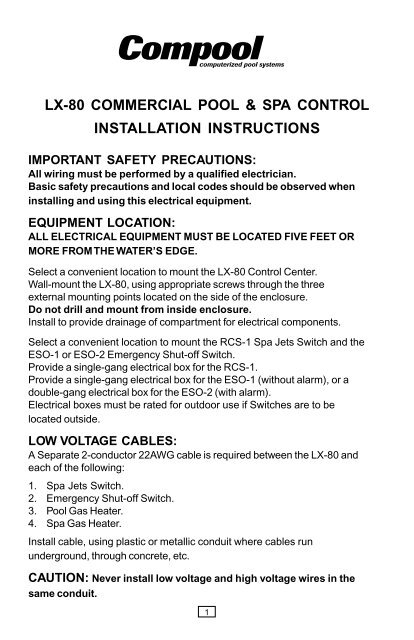
lx-80 commercial pool & spa control installation instructions - Pentair
lx-80 commercial pool & spa control installation instructions - Pentair
lx-80 commercial pool & spa control installation instructions - Pentair

Create successful ePaper yourself
Turn your PDF publications into a flip-book with our unique Google optimized e-Paper software.
LX-<strong>80</strong> COMMERCIAL POOL & SPA CONTROL<br />
INSTALLATION INSTRUCTIONS<br />
IMPORTANT SAFETY PRECAUTIONS:<br />
All wiring must be performed by a qualified electrician.<br />
Basic safety precautions and local codes should be observed when<br />
installing and using this electrical equipment.<br />
EQUIPMENT LOCATION:<br />
ALL ELECTRICAL EQUIPMENT MUST BE LOCATED FIVE FEET OR<br />
MORE FROM THE WATER’S EDGE.<br />
Select a convenient location to mount the LX-<strong>80</strong> Control Center.<br />
Wall-mount the LX-<strong>80</strong>, using appropriate screws through the three<br />
external mounting points located on the side of the enclosure.<br />
Do not drill and mount from inside enclosure.<br />
Install to provide drainage of compartment for electrical components.<br />
Select a convenient location to mount the RCS-1 Spa Jets Switch and the<br />
ESO-1 or ESO-2 Emergency Shut-off Switch.<br />
Provide a single-gang electrical box for the RCS-1.<br />
Provide a single-gang electrical box for the ESO-1 (without alarm), or a<br />
double-gang electrical box for the ESO-2 (with alarm).<br />
Electrical boxes must be rated for outdoor use if Switches are to be<br />
located outside.<br />
LOW VOLTAGE CABLES:<br />
A Separate 2-conductor 22AWG cable is required between the LX-<strong>80</strong> and<br />
each of the following:<br />
1. Spa Jets Switch.<br />
2. Emergency Shut-off Switch.<br />
3. Pool Gas Heater.<br />
4. Spa Gas Heater.<br />
Install cable, using plastic or metallic conduit where cables run<br />
underground, through concrete, etc.<br />
CAUTION: Never install low voltage and high voltage wires in the<br />
same conduit.<br />
1
LX-<strong>80</strong> CONTROL CENTER :<br />
Loosen LOCK SCREW on hinged faceplate located in left-side of LX-<strong>80</strong>,<br />
and swing open to expose the low voltage wiring compartment.<br />
Pull low voltage cables through holes in bottom left-side of LX-<strong>80</strong>.<br />
Strip wires ¼” and connect to circuit board at appropriate screw<br />
terminals in accordance with low voltage wiring diagram located inside<br />
enclosure cover.<br />
NOTE: For the convenience of the serviceperson, the 10 position screw<br />
terminal can be plugged from the circuit board without disconnecting wires.<br />
RCS-1 SPA JETS SWITCH :<br />
At the LX-<strong>80</strong>, connect 2-conductor cable form the Spa Jets Switch to<br />
circuit board at REM 1 screw terminals.<br />
At the Spa Jets Switch location, strip insulation of each wire ¼” and<br />
connect to screw terminals #3 and #4 on switch contact block.<br />
There is no polarity, so color-coding is unimportant.<br />
Position gasket over back of switchplate, and mount to electrical box,<br />
using mounting screws provided.<br />
EMERGENCY SHUT-OFF SWITCH :<br />
At the LX-<strong>80</strong>, connect 2-conductor cable for the Emergency Shut-off<br />
Switch to circuit board at SHUT OFF screw terminals.<br />
If model ESO-2 (with alarm) is being installed, connect green wire to the<br />
upper screw terminal and red wire to the lower screw terminal.<br />
If model ESO-1 is being installed, color-coding is unimportant.<br />
At the Emergency Shut-off Switch, strip insulation of each wire ¼”, and<br />
make appropriate connections to screw terminals #1 and #2 on switch<br />
contact block:<br />
For ESO-2, connect red wire to screw terminal #2 and green wire to<br />
screw terminal #1, but do not disconnect factory wiring between<br />
contact block and alarm.<br />
For ESO-1, color-coding in unimportant.<br />
Position gasket over back of switchplate, and mount to electrical box<br />
using mounting screws provided.<br />
CAUTION: If Emergency Shut-Off Switch is not installed, then a jumper<br />
wire must be connected between “SHUT OFF” screw terminals on<br />
circuit board.<br />
2
FIREMAN’S SWITCH CONNECTIONS :<br />
At the LX-<strong>80</strong>, connect 2-conductor cables from the Pool and Spa Gas<br />
Heaters to circuit board at the appropriate screw terminals:<br />
Connect Pool heater to POOL GHTR screw terminals, and Spa Heater<br />
to SPA GHTR screw terminals.<br />
Inside each gas heater (<strong>pool</strong> and <strong>spa</strong>), find fireman’s switch wire nut, or<br />
interrupt wire between thermostat and gas valve, and connect 2-conductor<br />
cable with wire nuts, in accordance with wiring diagram.<br />
Do not disconnect high limit and pressure switches.<br />
CAUTION: If optional Temperature Control Modules (model MOD-SOL) are<br />
being used, heater thermostats must be overridden. To accomplish this, turn<br />
thermostat switch to “ON”, “HIGH” or “SPA” (depending on the type of heater<br />
used), and set dial to highest temperature possible.<br />
LOW VOLTAGE WIRING:<br />
3
HIGH VOLTAGE WIRING :<br />
All high voltage connections are made to terminal blocks, which are<br />
located behind service panel in right-side compartment of LX-<strong>80</strong>.<br />
A wiring label is located adjacent to terminal blocks.<br />
Knock-out holes are provided on bottom of enclosure for conduit mounting.<br />
Install an electrical sub-panel with separate breakers for each load.<br />
Provide a separate circuit breaker (if possible) to power the system.<br />
Either 115VAC or 230VAC can be used. System draws less than 1 amp.<br />
Run wires from circuit breaker to high voltage compartment of LX-<strong>80</strong>, and<br />
connect to top terminal block which is marked “SYSTEM POWER”.<br />
Install 2 jumpers for 115V, or 1 jumper for 230V wiring, according to<br />
wiring label.<br />
Provide independent circuit breakers (if possible) for R1 (POOL FLTR),<br />
R2 (SPA FLTR) and R3 (JETS 1).<br />
Run wires from breakers to high voltage compartment of LX-<strong>80</strong>, and<br />
connect to LINE 1 and LINE 2 terminals of appropriate terminal block.<br />
Connect pumps and other high voltage equipment to LOAD 1 and LOAD 2<br />
terminals at appropriate terminal block.<br />
Each individual terminal block can be wired for either 115VAC or 230VAC.<br />
For 115V equipment, only half of the terminal block will be used.<br />
CAUTION: If pumps exceed 2½ HP, the high voltage relay should be<br />
used to energize a magnetic starter.<br />
NOTE: Circuits for R4, R5, R6, and R7 are optional and require additional<br />
relay kits (model RLY-LX).<br />
A Relay Allocation Chart is provided inside enclosure cover for the<br />
serviceperson’s convenience.<br />
To reduce the risk of electric shock, provide a continuous green insulated<br />
copper wire, no smaller than #12AWG, between grounding bus of LX-<strong>80</strong><br />
and grounding terminal of electrical supply panel.<br />
Additionally, a wire connector is provided for bonding to local ground<br />
points, To further reduce the risk of electric shock, this connector should<br />
be bonded with a #8AWG copper wire to any metal ladders, water pipes,<br />
or other metal within five feet of the <strong>pool</strong> or <strong>spa</strong>.<br />
4
SYSTEMS OPTIONS<br />
TEMPERATURE CONTROL MODULES :<br />
It is possible to provide precision thermostatic <strong>control</strong> of the <strong>pool</strong> and<br />
<strong>spa</strong> heaters by adding Temperature Control Modules (model MOD-SOL)<br />
at the LX-<strong>80</strong>. A separate Module should be provided for each heater.<br />
Additionally, each Module contains a built-in solar <strong>control</strong> for the optional<br />
<strong>control</strong> of a booster pump or motorized valve, or both. This enables a<br />
separate solar system for each body of water.<br />
Install MOD-SOL in accordance with <strong>instructions</strong> provided.<br />
MULTIPLE SPA JET PUMPS OR BLOWERS :<br />
The standard system is provided with a relay to activate one jet pump or<br />
air blower. However, a combination of up to 4 jet pumps and / or air<br />
blowers can be <strong>control</strong>led by the Spa Jets Switch. A separate relay<br />
(model RLY-LX) should be added for each pump.<br />
Install RLY-LX in accordance with <strong>instructions</strong> provided.<br />
A second JETS 1 relay socket is provided on the circuit board.<br />
If more that 2 pumps are being used, install an adapter (model RYA-LX)<br />
in which to plug two relays from one relay socket.<br />
DUAL REMOTE CONTROLS :<br />
A second Spa Jets Switch (model RCS-1) may be added to the system to<br />
activate up to 2 more pumps.<br />
Install RCS-1 in accordance with previous <strong>instructions</strong>, and connect<br />
2-conductor cable to LX-<strong>80</strong> circuit board at REM 2 screw terminals.<br />
Additonal relays (model RLY-LX) should be installed for each pump.<br />
Plug RLY-LX into LX-<strong>80</strong> circuit board at JETS 2 relay socket(s).<br />
POOL CHLORINE PUMP :<br />
A <strong>pool</strong> filter pump is less than 2HP, the POOL FLTR relay (R1) can be<br />
used to actuate a separate chlorine pump.<br />
If <strong>pool</strong> filter pump is 2HP to 2½HP, a separate relay (model RLY-LX)<br />
should be used to actuate the chlorine pump.<br />
Install RLY-LX in accordance with <strong>instructions</strong>, and plug into circuit board<br />
at POOL ORP relay socket.<br />
SPA CHLORINE PUMP :<br />
If <strong>spa</strong> filter pump is less than 2HP, the SPA FLTR relay (R2) can be used<br />
to actuate a separate chlorine pump.<br />
If <strong>spa</strong> filter pump is 2HP to 2½HP, a separate relay (model RLY-LX)<br />
should be used to actuate the chlorine pump.<br />
Use an adapter (model RYA-LX) in order to plug both relays into the<br />
circuit board at SPA FLTR relay socket.<br />
5
OPERATING INSTRUCTIONS<br />
POOL/SPA TIMER<br />
To set the correct time of day :<br />
Rotate the dial in a clockwise direction until the hours and minutes line-up<br />
with the white arrow at eight o’clock position on the clock face.<br />
Pay particular attention to the AM and PM sections of the dial.<br />
To program operating time(s) :<br />
Depress number of sections around the perimeter of the dial by pushing<br />
towards the center. For each section depressed, the equipment will operate<br />
for 15 minutes.<br />
POOL/SPA FILTER<br />
NOTE: Whenever filter pump is running, water will automatically heat<br />
up to the preset temperature.<br />
Service Switch positions :<br />
TIMER Keep in this position for normal system operation.<br />
OFF Turns filter pump off (for service purpose only).<br />
ON Turns filter pump on (for service purpose only).<br />
To override Fireman’s Switch :<br />
Whenever the timer shuts off, the filter pump will continue to run for an<br />
additional ten minutes to cool down the heater and protect the equipment<br />
from overheating.<br />
In order to cancel this “delay” (for service purpose), switch to OFF and then<br />
back to TIMER position.<br />
Status Light :<br />
PUMP ON Indicates whenever filter pump is running.<br />
SPA JETS<br />
Service Switch positions :<br />
40 MIN Remote Switch will activate jets for 40 minute cycle.<br />
20 MIN Remote Switch will activate jets for 20 minute cycle.<br />
TEST Remote Switch will activate jets for 5 seconds (for service purposes).<br />
Status Lights :<br />
JETS 1 Indicates whenever Remote Switch is running.<br />
JETS 2 Indicates whenever optional second Remote Switch is running.<br />
6
SPA PRIORITY<br />
Service Switch positions :<br />
TIMER Spa jets, filter pump, and heater will operate only when<br />
SPA TIMER is on.<br />
Whenever SPA TIMER is off, Remote Switch is disabled.<br />
REMOTES Spa jets, filter pump and heater will operate whenever<br />
Remote Switch is activated, regardless of SPA TIMER position.<br />
POOL/SPA HEATING (Optional)<br />
Service Switch positions :<br />
SOLAR Allows heating with solar only.<br />
SOL PREF Allows preferential heating with solar, but automatically<br />
switches to conventional heating when solar energy is<br />
unavailable.<br />
HEATER Allows heating with gas or electric heater only.<br />
OFF Allows no heating.<br />
Status Lights :<br />
HEATER ON Indicates whenever heater is on.<br />
SOLAR ON Indicates whenever solar is on.<br />
Pool and Spa Thermostats :<br />
Set THERMOSTAT dial(s) to the desired water temperature.<br />
NOTE: Make sure that separate thermostat on heater is turned all the way up.<br />
If optional Temperature Control Module is not used, use separate thermostat<br />
on heater to set desired water temperature.<br />
REMOTE SWITCH<br />
To operate <strong>spa</strong> :<br />
Push Spa Jets button once to activate <strong>spa</strong>.<br />
To turn <strong>spa</strong> off :<br />
Spa will automatically switch off at the end of its cycle.<br />
To turn <strong>spa</strong> off during its cycle, push Spa Jets button a second time.<br />
A second Remote Switch may be used to <strong>control</strong> additional jets.<br />
This optional SPA JETS button will not activate the filter pump or heater.<br />
EMERGENCY SHUT-OFF SWITCH<br />
In the event of an emergency :<br />
Push Red button to automatically shut-off all <strong>spa</strong> equipment.<br />
To reset :<br />
Pull out Red button in order to reset <strong>spa</strong> equipment.<br />
7
ONE YEAR LIMITED WARRANTY<br />
<strong>Pentair</strong> Pool Products warrants to the purchaser of the Electronic Control<br />
System, for a period of one (1) year for the date of original purchase for use,<br />
that any defective product proved to be caused by faulty workmanship for<br />
faulty material, will be repaired or replaced at <strong>Pentair</strong> Pool Products option for<br />
no charge, providing the product is returned to <strong>Pentair</strong> Pool Products, with all<br />
transportation charges prepaid.<br />
No allowances will be made for labor for the removal or re<strong>installation</strong> of any<br />
so-claimed defective products.<br />
This warranty covers the Control Center, Spa Jets Switch and Emergency<br />
Shut-off Switch, including all components and parts. It extends to the<br />
consumer who made the original retail purchase only and is not enforceable<br />
by any other party.<br />
This limited warranty applies only to Controls which have been installed and<br />
maintained in strict accordance with <strong>installation</strong> and operating <strong>instructions</strong><br />
provided by <strong>Pentair</strong> Pool Products, using <strong>installation</strong> hardware supplied and/or<br />
recommended in writing by <strong>Pentair</strong> Pool Products, and to Controls which have<br />
been connected to the correct supply voltage.<br />
This limited warranty does not apply to any Controls which have been repaired<br />
or altered by anyone other than <strong>Pentair</strong> Pool Products or a person authorized<br />
by it; or which have been subject to misuse, neglect, or accident; or which<br />
have been damaged by wind, freezing or other cause, thing, person or act of<br />
God; or which have been subject to damage in transit, during <strong>installation</strong>, or by<br />
someone other than <strong>Pentair</strong> Pool Products; or which have been damaged<br />
because of a defect in a component or part which is not part of the Com<strong>pool</strong><br />
Control System; or upon which the serial number or manufacture date has<br />
been altered, effaced or removed.<br />
Unless state law provides otherwise, <strong>Pentair</strong> Pool Products shall not be liable<br />
for consequential or incidental damages resulting from breach of this written<br />
warranty or any implied warranty, or for any inconvenience, loss of time, or<br />
incidental expenses such as telephone calls.<br />
To exercise this warranty, send defective unit with copy of dated receipt and<br />
a brief description of the problems encountered, postage prepaid, to:<br />
PENTAIR POOL PRODUCTS<br />
10951 West Los Angeles Ave., Moorpark, CA 93021 • (<strong>80</strong>5) 523-2400<br />
941-0688<br />
8