- Page 1 and 2:
EE 660 Application of Power Electro
- Page 3 and 4:
Books for Reference • T. J. E. Mi
- Page 5 and 6:
• Consumption of Electricity are
- Page 7 and 8:
• Thermal limit (depends on ambie
- Page 9 and 10:
• Voltage profile along the line
- Page 11 and 12:
• To control V R & ↑ power tran
- Page 13 and 14:
• High ‘V’ & high KVar source
- Page 15 and 16:
• What sort of PWM technique to u
- Page 17 and 18:
V = V = V = m S R V It can be shown
- Page 19 and 20:
Provide • Series capacitive compe
- Page 21 and 22:
• Is it possible to change the ph
- Page 23 and 24:
• Injecting V in series with line
- Page 25 and 26:
• Definite amount of power that s
- Page 27 and 28:
• To control the power flow & to
- Page 29 and 30:
• Most of the loads are Non-linea
- Page 31 and 32:
Current drawn by the load fed from
- Page 33 and 34:
Effect of harmonics: A. In the Rota
- Page 35 and 36:
Conclusions • Load compensator +
- Page 37 and 38:
Notation of quality of supply • H
- Page 39 and 40:
Ideal compensator • Correct the p
- Page 41 and 42:
Voltage regulation • Which is the
- Page 43 and 44:
I L = P L − V jQ L ΔV = ( R + jX
- Page 45 and 46:
Vary Q S => ΔV rotates till E = V
- Page 47 and 48:
• Approximate relationship for vo
- Page 49 and 50:
• If short circuit resistance of
- Page 51 and 52:
I a = V R ab Vca − jX VL∠0 V∠
- Page 53 and 54:
I b = I c ∠120 ⎛ ⎜ ⎝ 3 2X
- Page 55 and 56:
Contd.. • Using passive reactive
- Page 57 and 58:
Comments • Branch currents of Δ
- Page 59 and 60:
Application of Power Electronics in
- Page 61 and 62:
• May not be possible • Most of
- Page 63 and 64:
• Can be shown that if V < C1 V S
- Page 65 and 66:
• M => Magnitude of sine wave (no
- Page 67 and 68:
Review • Linear lagging load can
- Page 69 and 70:
Contd.. • If space vector PWM is
- Page 71 and 72:
⇒ (n-1) harmonics are eliminated
- Page 73 and 74:
• Assume that there are 5 switchi
- Page 75 and 76:
• Non-linear transcendental equat
- Page 77 and 78:
How to calculate Ref. Var ? i = I m
- Page 79 and 80:
Controlled current SLCVC • Compen
- Page 81 and 82:
Control strategy -I Application of
- Page 83 and 84:
Review • In harmonic elimination
- Page 85 and 86:
Contd.. Controlled current SLCVC
- Page 87 and 88:
• i S * is in phase with v S •
- Page 89 and 90:
• If Inverter i S * is changed in
- Page 91 and 92:
• Use two compensators & connect
- Page 93 and 94:
• Main compensator ⇒ Voltage co
- Page 95 and 96:
i Cm1 = V S −VCm 1∠ −δ Z∠
- Page 97 and 98:
• Var calculator determines V * d
- Page 99 and 100:
Contd.. • For high power applicat
- Page 101 and 102:
[A] [v'] = [z] [A] [i'] [v'] = [A]
- Page 103 and 104:
Vector representation of instantane
- Page 105 and 106:
[ C] t = ⎡ ⎢ ⎢− ⎢ ⎣−
- Page 107 and 108:
⎡v ⎢ ⎢ v ⎢⎣ v a b c ⎤
- Page 109 and 110:
e e i i α β α β = = V V S S cos
- Page 111 and 112:
Application of Power Electronics in
- Page 113 and 114:
e . q i * = β α C 3 2 + ( 2 2 ) e
- Page 115 and 116:
• Frequency of e α , i α , e β
- Page 117 and 118:
Review Instantaneous real power P =
- Page 119 and 120:
Contd.. Application of Power Electr
- Page 121 and 122:
Change of reference frame q S d S d
- Page 123 and 124:
• Let us assume that v S is along
- Page 125 and 126:
• AC filtering ⇒ phase shift
- Page 127 and 128:
• Information about system freque
- Page 129 and 130:
* x ∫ ω xt () x y n + 1 − Δ t
- Page 131 and 132:
e α = e a − 1 2 e b − 1 2 e c
- Page 133 and 134:
e d e d = = = e e s e s α cos( θ
- Page 135 and 136:
Review • In synchronous rotating
- Page 137 and 138:
To change MI using harmonic elimina
- Page 139 and 140:
Application of Power Electronics in
- Page 141 and 142:
• 3φ sinusoids which are in phas
- Page 143 and 144:
• This voltage waveform can be us
- Page 145 and 146:
1 1 • = = Switching frequency T T
- Page 147 and 148:
• Assume that over one cycle V re
- Page 149 and 150:
Rule to be followed • A term in t
- Page 151 and 152:
S 4 , S 3 ON for DT S : di L = V s
- Page 153 and 154:
Aim • i s and V s should be in ph
- Page 155 and 156:
Contd.. • Generate reset pulse at
- Page 157 and 158:
1φ AC-DC Control technique (1 −
- Page 159 and 160:
Alternate Approach DC-DC Converter
- Page 161 and 162:
• Information regarding V s shoul
- Page 163 and 164:
Application of Power Electronics in
- Page 165 and 166:
Inverter topology for high power ap
- Page 167 and 168:
• Number of pulse should be high
- Page 169 and 170:
Switches ON V AX S1, S2 V dc S2, S3
- Page 171 and 172:
Application of Power Electronics in
- Page 173 and 174:
Review • In one cycle control ‘
- Page 175 and 176:
Contd.. • At any time 2-devices (
- Page 177 and 178:
4-level inverter • Number of swit
- Page 179 and 180:
S2, S3, S4 ON : ⇒ V AX = 2V dc /3
- Page 181 and 182:
• ‘V’ rating of D B = 2V dc /
- Page 183 and 184:
Voltage space vectors for 3 level i
- Page 185 and 186:
( NNP ) ⇒ ( 001 ) ⇒ ( PPN ) ⇒
- Page 187 and 188:
C B A O O N O N O N O O C B A O N N
- Page 189 and 190:
V q ∴V S = = 3 2 V 2 dC ⎡V ⎢
- Page 191 and 192:
OOP : V AO = V dC /2, V BO = V CO =
- Page 193 and 194:
OPO : V AO = V CO = 0, V BO = V dC
- Page 195 and 196:
Medium voltage vectors ONP : V AO =
- Page 197 and 198:
NPO : V AO = 0, V BO = V dC /2 , V
- Page 199 and 200:
Application of Power Electronics in
- Page 201 and 202:
Contd.. • No. of medium voltage v
- Page 203 and 204:
Voltage control • Space vector PW
- Page 205 and 206:
• Unbalances has no effect on loa
- Page 207 and 208:
• Passive elements Load compensat
- Page 209 and 210:
Shunt Compensation : • Inject cur
- Page 211 and 212:
Mid point voltage regulator • Two
- Page 213 and 214:
Application of Power Electronics in
- Page 215 and 216:
• Reactive power supplied by the
- Page 217 and 218:
• Shunt compensator can increase
- Page 219 and 220:
Review Mid-point shunt compensation
- Page 221 and 222: Summary • Compensator must remain
- Page 223 and 224: Variable impedance type S.V.C 1. Th
- Page 225 and 226: • ‘i’ is continuous when α =
- Page 227 and 228: 2. Thyristor switched capacitor (TS
- Page 229 and 230: 3. Fixed Capacitor, Thyristor contr
- Page 231 and 232: • At α = π/2, Q L = Q L(max)
- Page 233 and 234: Control • ‘Q’ is controlled b
- Page 235 and 236: Operating V-I region Application of
- Page 237 and 238: Contd.. T.S.C • Thyristors are tr
- Page 239 and 240: Advantages • Since voltage profil
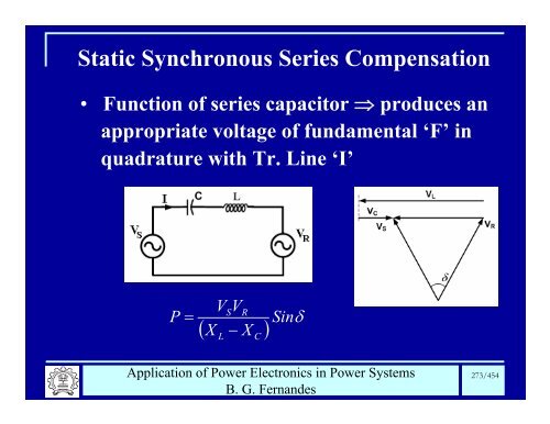
- Page 241 and 242: Series compensation • Injects vol
- Page 243 and 244: X eff = ( X − X ) L C = ( 1− K
- Page 245 and 246: Q Q se sh = tan ⎛ ⎜ ⎝ 2 δ ma
- Page 247 and 248: Approaches to controllable series c
- Page 249 and 250: • Amplitude of the fundamental V
- Page 251 and 252: (b). Impedance compensation mode: V
- Page 253 and 254: Review GTO controlled series capaci
- Page 255 and 256: Contd.. • Control ‘i’ in ‘L
- Page 257 and 258: Voltage compensating mode : • Rea
- Page 259 and 260: • In FCTCR continuously varying c
- Page 261 and 262: V 2 1 I1 ⎜ Sin X ⎝ π π ⎛
- Page 263 and 264: Application of Power Electronics in
- Page 265 and 266: • If X L (α) < X C , There are t
- Page 267 and 268: • ‘V C ’ gets distorted • I
- Page 269 and 270: • If X TCR = 1.5X C ⇒ Capacitiv
- Page 271: Modes of operation By pass mode :
- Page 275 and 276: • Voltage across ‘L’ ⇒ V (
- Page 277 and 278: Contd.. • For both region X L < X
- Page 279 and 280: Control range: • Voltage compensa
- Page 281 and 282: • Compensation for both reactive
- Page 283 and 284: • If V S = V R =V Per phase power
- Page 285 and 286: ⇒ Reactive VA associated with the
- Page 287 and 288: Voltage & phase angle regulators Vo
- Page 289 and 290: Power flow control : • Optimal lo
- Page 291 and 292: • Basic idea is to keep the trans
- Page 293 and 294: UPFC : • Able to control simultan
- Page 295 and 296: • Independently control the react
- Page 297 and 298: Case1 : Control capabilities ρ = 0
- Page 299 and 300: U.P.F.C : Review • Two VSI connec
- Page 301 and 302: Using UPFC • Active power flow an
- Page 303 and 304: ⇒ A common DC-link voltage is reg
- Page 305 and 306: = Ve ⎧V ⎨ ⎩ ( Cosδ 2 − jSi
- Page 307 and 308: • ‘ρ’ can vary from 0 to 2π
- Page 309 and 310: ⇒ Shunt current is controlled ind
- Page 311 and 312: FACTS installments in India • TSC
- Page 313 and 314: HVDC • Long distance transmission
- Page 315 and 316: Back to Back : • Chandrapur - Ram
- Page 317 and 318: • ‘P’ through link can not be
- Page 319 and 320: • If alternator-2 generates 1000
- Page 321 and 322: Application of Power Electronics in
- Page 323 and 324:
• One conductor (generally -ve)
- Page 325 and 326:
• Each terminal has two converter
- Page 327 and 328:
Components of HVDC transmission Bi-
- Page 329 and 330:
Smoothing Reactor : Large value of
- Page 331 and 332:
Reactive power support : • Both c
- Page 333 and 334:
• If α 1 is trigger angle for br
- Page 335 and 336:
⇒T 1 is turned off at ωt= 30+ (3
- Page 337 and 338:
At ωt = 210 o V a = Sin210 = −1
- Page 339 and 340:
At ωt = 330 o V a −1 2, V = 1 =
- Page 341 and 342:
At ωt = 300 o V − 3 2, V = 0 V =
- Page 343 and 344:
Vdc = 2.34V ph. Cosα =1.35V LL .Co
- Page 345 and 346:
Contd.. • As α 1 ↑ (AC-DC conv
- Page 347 and 348:
Phase relationship between phase V
- Page 349 and 350:
As α↑: • V dc ↓ • Displace
- Page 351 and 352:
Boundary conditions : At ωt = α,
- Page 353 and 354:
∴V 0 = V pn −V mn V = − 2 cn
- Page 355 and 356:
Representation of inverter mode of
- Page 357 and 358:
Converter α ⇒ delay angle μ ⇒
- Page 359 and 360:
V dco = [cos + cos γ ] − − −
- Page 361 and 362:
12-pulse converter • Series conne
- Page 363 and 364:
Application of Power Electronics in
- Page 365 and 366:
V d ⎛ 3 = VdoCosα − Id . B.
- Page 367 and 368:
• 24/36 harmonic filter ⇒ 2*80
- Page 369 and 370:
Direct current : • Nominal I ⇒
- Page 371 and 372:
Basic control : • DC voltage or I
- Page 373 and 374:
Basis for selection of control : Fo
- Page 375 and 376:
• Denominator is very small • A
- Page 377 and 378:
• P.F should be as high as possib
- Page 379 and 380:
• γ ⇒ necessary to maintain a
- Page 381 and 382:
I d = V dcor Cosα −V R + R + cr
- Page 383 and 384:
• Maintains adequate commutation
- Page 385 and 386:
• As taps are changed, CEA regula
- Page 387 and 388:
Basic control : • DC voltage or I
- Page 389 and 390:
Basis for selection of control : Fo
- Page 391 and 392:
• Rectifier control ⇒ To preven
- Page 393 and 394:
Control of HVDC system Application
- Page 395 and 396:
• Quantities forming the co-ordin
- Page 397 and 398:
• Rectifier characteristics can b
- Page 399 and 400:
• Constant current characteristic
- Page 401 and 402:
• After some time, tap changer ch
- Page 403 and 404:
• Therefore rectifier characteris
- Page 405 and 406:
• At normal voltage , characteris
- Page 407 and 408:
• In order to avoid the problem,
- Page 409 and 410:
• When inverter is on current con
- Page 411 and 412:
When does change over take place ?
- Page 413 and 414:
Review Rectifier characteristics Co
- Page 415 and 416:
• ‘e’ is -ve, ‘K’ is +ve
- Page 417 and 418:
• Due to line fault or during low
- Page 419 and 420:
Inverter side : • I d can be ↑
- Page 421 and 422:
Mode stabilization : • Intersecti
- Page 423 and 424:
• ‘V’ profile is flat • Con
- Page 425 and 426:
• V dcoi Cosβ remains constant
- Page 427 and 428:
Current limit Maximum current limit
- Page 429 and 430:
Voltage depend current-order limit
- Page 431 and 432:
• VDCOL characteristics could be
- Page 433 and 434:
Contd.. But I ref(R) > I ref(I) I r
- Page 435 and 436:
Contd.. Mode stabilization : • In
- Page 437 and 438:
Voltage depend current-order limit
- Page 439 and 440:
• VDCOL characteristics could be
- Page 441 and 442:
Application of Power Electronics in
- Page 443 and 444:
Significant aspects of basic contro
- Page 445 and 446:
• If there is a ↓ in AC voltage
- Page 447 and 448:
⇒ Achieved using by pass valve an
- Page 449 and 450:
• For energization of blocked bri
- Page 451 and 452:
• Instead use VSI • ‘I’ cou
- Page 453 and 454:
• ‘V’ can not reverse, but