Multilayer dielectric structure for enhancement of evanescent waves
Multilayer dielectric structure for enhancement of evanescent waves
Multilayer dielectric structure for enhancement of evanescent waves

Create successful ePaper yourself
Turn your PDF publications into a flip-book with our unique Google optimized e-Paper software.
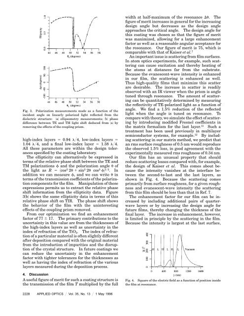
Fig. 3. Polarization measurements made as a function <strong>of</strong> the<br />
incident angle on linearly polarized light reflected from the<br />
<strong>dielectric</strong> <strong>structure</strong>: 1a2 ellipsometry measurements; 1b2 phase<br />
difference between TE and TM light shift deduced from 1a2 by<br />
removing the effects <strong>of</strong> the coupling prism.<br />
high-index layers 5 0.94 l@4, low-index layers 5<br />
1.04 l@4, and a final low-index layer 5 1.38 l@4.<br />
All these parameters are within the design tolerances<br />
specified by the coating laboratory.<br />
The ellipticity can alternatively be expressed in<br />
terms <strong>of</strong> the relative phase shift between the TE and<br />
TM polarizations f and the polarization angle u <strong>of</strong><br />
the light as R 5 1cos 2 2u1sin 2 2u cos 2 f2 1@2 . In<br />
addition we can measure f, and we can write u in<br />
terms <strong>of</strong> the transmission coefficients <strong>of</strong> the polarization<br />
components <strong>for</strong> the film. Manipulation <strong>of</strong> these<br />
expressions permits us to extract the relative phase<br />
shift in<strong>for</strong>mation from the ellipticity data. Figure<br />
31b2 shows the same ellipticity data in terms <strong>of</strong> this<br />
relative phase shift on TIR. The phase shift shows<br />
the behavior <strong>of</strong> the film with the uninteresting<br />
effects <strong>of</strong> the coupling prism removed.<br />
From our optimization we find an <strong>enhancement</strong><br />
factor <strong>of</strong> 77 6 17. The primary contributions to the<br />
uncertainty in this value are from the thicknesses <strong>of</strong><br />
the high-index layers as well as uncertainty in the<br />
index <strong>of</strong> refraction <strong>of</strong> the TiO 2 . The index <strong>of</strong> refraction<br />
<strong>of</strong> a particular material is <strong>of</strong>ten slightly different<br />
after deposition compared with the original material<br />
from the introduction <strong>of</strong> impurities and the disruption<br />
<strong>of</strong> the crystal <strong>structure</strong>. In future coatings we<br />
can reduce the uncertainty in the <strong>enhancement</strong><br />
factor with tighter tolerances <strong>for</strong> the thicknesses as<br />
well as having the index <strong>of</strong> refraction <strong>of</strong> the various<br />
layers measured during the deposition process.<br />
4. Discussion<br />
A useful figure <strong>of</strong> merit <strong>for</strong> such a coating <strong>structure</strong> is<br />
the transmission <strong>of</strong> the film T multiplied by the full<br />
width at half-maximum <strong>of</strong> the resonance Du. The<br />
figure <strong>of</strong> merit increases in general <strong>for</strong> the increasing<br />
design angle but decreases as the design angle<br />
approaches the critical angle. The design angle <strong>for</strong><br />
this coating was chosen so that the figure <strong>of</strong> merit<br />
was maximized, allowing <strong>for</strong> a large <strong>enhancement</strong><br />
factor as well as a reasonable angular acceptance <strong>for</strong><br />
the resonance. Our figure <strong>of</strong> merit is 75, which is<br />
comparable with that <strong>of</strong> Kaiser et al. 7<br />
An important issue is scattering from film surfaces.<br />
In atom optics experiments, <strong>for</strong> example, such scattering<br />
can cause excitation and thereby heating <strong>of</strong><br />
the atoms at distances far from the substrate.<br />
Because the <strong>evanescent</strong>-wave intensity is enhanced<br />
in our film, the scattering is enhanced as well.<br />
Thus high-quality films that minimize this scatter<br />
are desirable. The increase in scatter is readily<br />
observed with an IR viewer when the prism is angle<br />
tuned through resonance. The amount <strong>of</strong> scattering<br />
can be quantitatively determined by measuring<br />
the reflectivity <strong>of</strong> TE-polarized light as a function <strong>of</strong><br />
angle. We find a 1.5% reduction <strong>of</strong> the reflected<br />
light when the angle is tuned on resonance. To<br />
compare with theory, we simulate the effect <strong>of</strong> scattering<br />
by introducing modified Fresnel coefficients in<br />
the matrix <strong>for</strong>malism <strong>for</strong> the last layer. 11 Such a<br />
treatment has been used previously in multilayer<br />
semiconductor systems, <strong>for</strong> example. 12 By including<br />
scattering in our matrix method, we predict that<br />
an rms surface roughness <strong>of</strong> 0.5 nm would reproduce<br />
the observed 1.5% loss, in good agreement with the<br />
experimentally measured rms roughness <strong>of</strong> 0.34 nm.<br />
Our film has an unusual property that should<br />
reduce scattering losses compared with, <strong>for</strong> example,<br />
the design <strong>of</strong> Kaiser et al. This comes about because<br />
the intensity vanishes at the interface between<br />
the second-to-last and the last layers, as<br />
shown in Fig. 4. Because the scattering comes<br />
primarily from surface roughness, <strong>for</strong> a given roughness<br />
and <strong>evanescent</strong>-wave intensity the scattering<br />
from this film should be less than that in Ref. 7.<br />
The <strong>enhancement</strong> factor <strong>for</strong> our film can be increased<br />
by including additional pairs <strong>of</strong> quarterwave<br />
layers or by increasing the design angle <strong>for</strong><br />
future films, thereby changing the thickness <strong>of</strong> the<br />
final layer. The increase in <strong>enhancement</strong>, however,<br />
is limited in principle by the scattering in the film.<br />
Because the intensity is largest at the last surface,<br />
Fig. 4. Square <strong>of</strong> the electric field as a function <strong>of</strong> position inside<br />
the film at resonance.<br />
2228 APPLIED OPTICS @ Vol. 35, No. 13 @ 1 May 1996
![The Symmetric Linear Potential [ ]](https://img.yumpu.com/25329322/1/190x245/the-symmetric-linear-potential-.jpg?quality=85)