model EAA-645 - Pottorff
model EAA-645 - Pottorff
model EAA-645 - Pottorff

You also want an ePaper? Increase the reach of your titles
YUMPU automatically turns print PDFs into web optimized ePapers that Google loves.
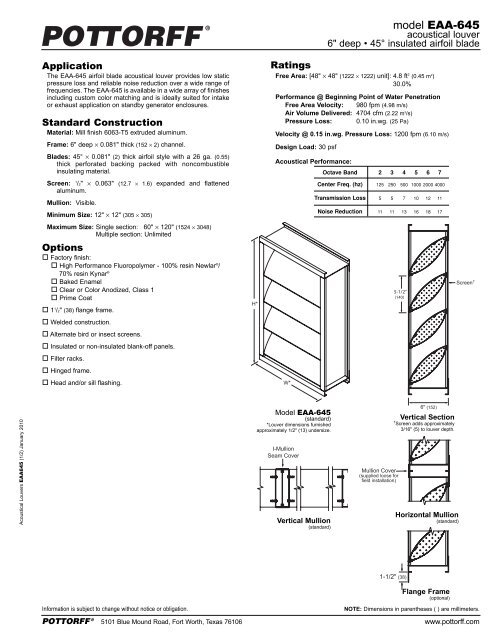
<strong>model</strong> <strong>EAA</strong>-<strong>645</strong><br />
acoustical louver<br />
6" deep • 45° insulated airfoil blade<br />
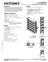
Application<br />
The <strong>EAA</strong>-<strong>645</strong> airfoil blade acoustical louver provides low static<br />
pressure loss and reliable noise reduction over a wide range of<br />
frequencies. The <strong>EAA</strong>-<strong>645</strong> is available in a wide array of finishes<br />
including custom color matching and is ideally suited for intake<br />
or exhaust application on standby generator enclosures.<br />
Standard Construction<br />
Material: Mill finish 6063-T5 extruded aluminum.<br />
Frame: 6" deep 0.081" thick (152 2) channel.<br />
Blades: 45° 0.081" (2) thick airfoil style with a 26 ga. (0.55)<br />
thick perforated backing packed with noncombustible<br />
insulating material.<br />
Screen: 1 /2" 0.063" (12.7 1.6) expanded and flattened<br />
aluminum.<br />
Mullion: Visible.<br />
Minimum Size: 12" 12" (305 305)<br />
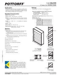
Ratings<br />
Free Area: [48" 48" (1222 1222) unit]: 4.8 ft 2 (0.45 m 2 )<br />
30.0%<br />
Performance @ Beginning Point of Water Penetration<br />
Free Area Velocity: 980 fpm (4.98 m/s)<br />
Air Volume Delivered: 4704 cfm (2.22 m 3 /s)<br />
Pressure Loss: 0.10 in.wg. (25 Pa)<br />
Velocity @ 0.15 in.wg. Pressure Loss: 1200 fpm (6.10 m/s)<br />
Design Load: 30 psf<br />
Acoustical Performance:<br />
Octave Band<br />
Center Freq. (hz)<br />
Transmission Loss<br />
Noise Reduction<br />
2 3 4 5 6 7<br />
125 250 500 1000 2000 4000<br />
5 5 7 10 12 11<br />
11 11 13 16 18 17<br />
Maximum Size: Single section: 60" 120" (1524 3048)<br />
Multiple section: Unlimited<br />
Options<br />
Factory finish:<br />
High Performance Fluoropolymer - 100% resin Newlar ® /<br />
70% resin Kynar ®<br />
Baked Enamel<br />
Clear or Color Anodized, Class 1<br />
Prime Coat<br />
1 1 /2" (38) flange frame.<br />
Welded construction.<br />
Alternate bird or insect screens.<br />
Insulated or non-insulated blank-off panels.<br />
Filter racks.<br />
Hinged frame.<br />
Head and/or sill flashing.<br />
H*<br />
W*<br />
5-1/2”<br />
(140)<br />
Acoustical Louvers <strong>EAA</strong><strong>645</strong> (1/2) January 2010<br />
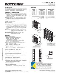
Model <strong>EAA</strong>-<strong>645</strong><br />
(standard)<br />
*Louver dimensions furnished<br />
approximately 1/2" (13) undersize.<br />
I-Mullion<br />
Seam Cover<br />
Vertical Mullion<br />
(standard)<br />
Mullion Cover<br />
(supplied loose for<br />
field installation)<br />
6" (152)<br />
Vertical Section<br />
† Screen adds approximately<br />
3/16" (5) to louver depth.<br />
Horizontal Mullion<br />
(standard)<br />
1-1/2" (38)<br />
Flange Frame<br />
(optional)<br />
Information is subject to change without notice or obligation.<br />
NOTE: Dimensions in parentheses ( ) are millimeters.<br />
POTTORFF ® 5101 Blue Mound Road, Fort Worth, Texas 76106 www.pottorff.com
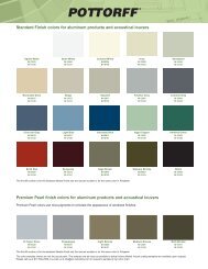
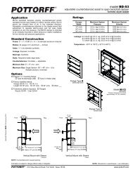
Performance Data<br />
Free Area (ft 2 )<br />
Height (Inches)<br />
Pressure Loss<br />
Width (Inches)<br />
12 18 24 30 36 42 48 54 60 66 72 78 84 90 96 102 108 114 120<br />
12 0.1 0.2 0.2 0.3 0.3 0.4 0.5 0.5 0.6 0.6 0.7 0.8 0.8 0.9 0.9 1.0 1.1 1.1 1.2<br />
18 0.3 0.4 0.6 0.7 0.9 1.0 1.2 1.3 1.5 1.7 1.8 2.0 2.1 2.3 2.4 2.6 2.7 2.9 3.1<br />
24 0.4 0.7 0.9 1.2 1.4 1.7 1.9 2.2 2.4 2.7 2.9 3.2 3.4 3.7 3.9 4.2 4.4 4.7 4.9<br />
30 0.6 0.9 1.3 1.6 2.0 2.3 2.7 3.0 3.3 3.7 4.0 4.4 4.7 5.1 5.4 5.8 6.1 6.5 6.8<br />
36 0.7 1.2 1.6 2.1 2.5 2.9 3.4 3.8 4.3 4.7 5.1 5.6 6.0 6.5 6.9 7.3 7.8 8.2 8.7<br />
42 0.9 1.4 2.0 2.5 3.0 3.6 4.1 4.6 5.2 5.7 6.3 6.8 7.3 7.9 8.4 8.9 9.5 10.0 10.5<br />
48 1.1 1.7 2.3 2.9 3.6 4.2 4.8 5.5 6.1 6.7 7.4 8.0 8.6 9.3 9.9 10.5 11.1 11.8 12.4<br />
54 1.2 1.9 2.7 3.4 4.1 4.8 5.6 6.3 7.0 7.7 8.5 9.2 9.9 10.6 11.4 12.1 12.8 13.6 14.3<br />
60 1.4 2.2 3.0 3.8 4.7 5.5 6.3 7.1 7.9 8.8 9.6 10.4 11.2 12.0 12.9 13.7 14.5 15.3 16.1<br />
66 1.5 2.4 3.4 4.3 5.2 6.1 7.0 7.9 8.9 9.8 10.7 11.6 12.5 13.4 14.4 15.3 16.2 17.1 18.0<br />
72 1.7 2.7 3.7 4.7 5.7 6.7 7.8 8.8 9.8 10.8 11.8 12.8 13.8 14.8 15.8 16.9 17.9 18.9 19.9<br />
78 1.8 3.0 4.1 5.2 6.3 7.4 8.5 9.6 10.7 11.8 12.9 14.0 15.1 16.2 17.3 18.4 19.5 20.7 21.8<br />
84 2.0 3.2 4.4 5.6 6.8 8.0 9.2 10.4 11.6 12.8 14.0 15.2 16.4 17.6 18.8 20.0 21.2 22.4 23.6<br />
90 2.2 3.5 4.8 6.1 7.3 8.6 9.9 11.2 12.5 13.8 15.1 16.4 17.7 19.0 20.3 21.6 22.9 24.2 25.5<br />
96 2.3 3.7 5.1 6.5 7.9 9.3 10.7 12.1 13.5 14.8 16.2 17.6 19.0 20.4 21.8 23.2 24.6 26.0 27.4<br />
102 2.5 4.0 5.5 6.9 8.4 9.9 11.4 1.9 14.4 15.9 17.3 18.8 20.3 21.8 23.3 24.8 26.3 27.8 29.2<br />
108 2.6 4.2 5.8 7.4 9.0 10.5 12.1 13.7 15.3 16.9 18.5 20.0 21.6 23.2 24.8 26.4 27.9 29.5 31.1<br />
114 2.8 4.5 6.1 7.8 9.5 11.2 12.9 14.5 16.2 17.9 19.6 21.2 22.9 24.6 26.3 27.9 29.6 31.3 33.0<br />
120 3.0 4.7 6.5 8.3 10.0 11.8 13.6 15.4 17.1 18.9 20.7 22.4 24.2 26.0 27.8 29.5 31.3 33.1 34.8<br />
1.00<br />
0.10<br />
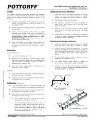
Selection Criteria<br />
Follow the steps listed below to calculate the louver size needed to satisfy the<br />
required air volume while minimizing the adverse effects of water penetration and<br />
pressure loss.<br />
1. Determine the Free Area Velocity (FAV) at the maximum allowable pressure loss<br />
using the Pressure Loss chart to the left. While job conditions vary, typically, the<br />
maximum allowable pressure loss should not exceed 0.15 in.wg., and the FAV for<br />
0.15 in.wg. pressure loss is listed on the front page of this sheet.<br />
2. Intake Applications If the FAV at the Beginning Point of Water Penetration<br />
(shown below) is less than the FAV from step 1, then use the FAV at the Beginning<br />
Point of Water Penetration in step 3, otherwise use the FAV from step 1.<br />
Exhaust Applications Use the FAV from step 1 in step 3.<br />
3. Calculate the total louver square footage required using the following equation.<br />
0.01<br />
100 1,000 10,000<br />
Louver Test Size = 48" x 48" (1219 x 1219)<br />
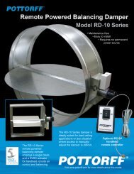
Water Penetration<br />
AMCA defines the beginning point of water penetration as the<br />
free area velocity at the intersection of a simple linear<br />
regression of test data and the line of 0.01 ounces of water<br />
per square foot of free area and is measured through a 48" <br />
48" louver during a 15 minute period. The AMCA water<br />
penetration test provides a method for comparing louver<br />
<strong>model</strong>s and designs as to their efficiency in resisting the<br />
penetration of rainfall under specific lab conditions. <strong>Pottorff</strong><br />
recommends that intake louvers are selected with a<br />
reasonable margin of safety below the beginning point of<br />
water penetration in order to avoid unwanted penetration<br />
during severe storm conditions.<br />
__________ cfm ÷ __________ fpm = __________ ft 2<br />
Required FAV Required Louver (Free-Area)<br />
Air Volume Size in ft 2<br />
4. Using the Free Area chart above, select a louver width and height that yields a<br />
free area ft 2 greater than or equal to the required louver size calculated in step 3.<br />
Water Penetration<br />
0.30<br />
0.25<br />
0.20<br />
0.15<br />
0.10<br />
0.05<br />
Beginning Point of Water Penetration = 980 fpm<br />
0.00<br />
900 950 1000 1050 1100 1150 1200<br />
Acoustical Louvers <strong>EAA</strong><strong>645</strong> (2/2) January 2010<br />
Information is subject to change without notice or obligation.<br />
NOTE: Dimensions in parentheses ( ) are millimeters.<br />
POTTORFF ® 5101 Blue Mound Road, Fort Worth, Texas 76106 www.pottorff.com