BLADE BALANCER
BLADE BALANCER
BLADE BALANCER

Create successful ePaper yourself
Turn your PDF publications into a flip-book with our unique Google optimized e-Paper software.
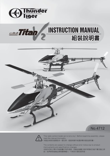
INSTRUCTION MANUAL<br />
<br />
No.4712<br />
This radio control model car is not a toy! Before beginning assembly, please<br />
read this manual thoroughly.<br />
本 產 品 為 高 性 能 模 型 非 一 般 玩 具 , 組 裝 與 操 作 前 請 詳 閱 本 產 品 說 明 書 。<br />
The contents are subject to change without prior notice due to product<br />
improvements and specificatrion changes.<br />
本 套 件 所 附 之 零 件 可 能 跟 圖 示 有 所 差 異 。 因 產 品 後 續 之 設 計 研 發 或 功 能 不 斷 改 善 之 原<br />
因 , 我 們 將 保 留 產 品 規 格 變 更 權 力 , 不 再 另 行 通 知 使 用 者 。
CONTENTS<br />
Introduction<br />
INTRO & CAUTION / 簡 介 與 注 意 事 項<br />
OTHER ITEMS REQUIRED / 其 餘 必 須 配 件<br />
ASSEMBLY / 組 裝 步 驟<br />
MAIN ROTOR / 主 旋 翼 機 構 組 裝<br />
LINKAGE ROD INSTALLATION / 連 桿 組 裝<br />
MAIN FRAME ASSEMBLY / 本 體 組 裝<br />
TAIL UNIT ASSEMBLY / 尾 管 組 裝<br />
TAIL BOOM BRACKET SET / 尾 管 固 定 座 組 裝<br />
ELECTRIC SYSTEM / 電 子 系 統<br />
CANOPY ASSEMBLY / 機 艙 罩 組 裝<br />
MAIN ROTOR <strong>BLADE</strong> ASSEMBLY / 主 旋 翼 組 裝<br />
INTRODUCTION OF E-CCPM CONTROL SYSTEM / E-CCPM 控 制 系 統 介 紹<br />
MOVEMENT OF 120°E-CCPM SYSTEM / E-CCPM 120° 說 明<br />
SERVO CONNECTING / 伺 服 機 連 結<br />
BASIC CONCEPT OF ADJUSTMENT / 基 礎 設 定 與 調 整<br />
SETTING UP OF LINKAGE / 連 桿 設 定<br />
SETTING UP MAIN ROTOR COLLECTIVE PITCH ANGLE / 主 旋 翼 螺 距 設 定<br />
SETTING UP DATA FOR YOUR REFERENCE / 設 定 參 考 值<br />
USING OF LI-PO BATTERY / 鋰 聚 電 池 使 用 注 意 事 項<br />
TROUBLE SHOOTING / 問 題 排 除<br />
HELI ACCESSORIES / 選 購 配 件<br />
BALL LINK REAMER (ø3.8MM) 球 頭 絞 刀<br />
ONE WAY BEARING RELEASER 單 向 軸 承 退 出 器<br />
<strong>BLADE</strong> <strong>BALANCER</strong> 主 旋 翼 平 衡 器<br />
TRAINING GEAR 直 昇 機 練 習 架<br />
SPARE PARTS / 零 件 表<br />
OPTION PASTS & ACCESSORIES / 選 購 零 配 件<br />
EXPLODED VIEW / 爆 炸 圖 檢 索<br />
SPECIFICATION & FEATURES / 規 格 表 & 特 色<br />
2<br />
4<br />
5<br />
6<br />
12<br />
13<br />
17<br />
21<br />
23<br />
27<br />
28<br />
29<br />
30<br />
31<br />
32<br />
35<br />
36<br />
38<br />
40<br />
40<br />
42<br />
42<br />
42<br />
43<br />
46<br />
47<br />
54<br />
56<br />
59<br />
Thunder Tiger<br />
-1-
INTRODUCTION / 簡 介<br />
Thank you for purchasing the Thunder Tiger mini Titan E325 V2 electric R/C helicopter. This new helicopter<br />
is the latest innovation by Thunder Tiger. It has the perfect combination of flying stability and the agility for<br />
3D flying. This helicopter is an excellent choice for flying enthusiasts like you. For convenient assembly<br />
and safe operation of the helicopter, please read the instructions carefully. Retain the user manual in case<br />
you need it for any information or reference.<br />
感 謝 您 購 買 雷 虎 科 技 小 型 電 動 直 昇 機 mini Titan E325 V2 產 品 , 本 項 產 品 為 雷 虎 科 技 全 新 開 發 機 種 , 兼 具 高 度 穩 定 性<br />
與 3D 飛 行 特 性 , 是 熱 衷 小 型 電 動 直 昇 機 的 您 不 可 錯 過 的 選 擇 。 請 於 使 用 本 產 品 前 詳 盡 閱 讀 使 用 手 冊 , 以 利 於 組 裝 工 作<br />
順 暢 進 行 與 安 全 操 控 本 產 品 。 請 妥 善 保 存 使 用 說 明 書 , 以 利 後 續 調 整 與 維 修 參 考 用 途 。<br />
CAUTION / 警 告<br />
1. R/C models are not toys. This product is a high-precision flying machine. Possibilities of unexpected<br />
crashes may occur due to electronic interference, incorrect operation, or poor mechanical maintenance.<br />
Although it is a small-sized helicopter, the rotor blades rotate at high speeds, which may cause serious<br />
damage, injury, or death if the model hits people or property. Therefore, extreme caution must be<br />
exercised during operation.<br />
2. Thunder Tiger ensures parts packaged in this product is of the highest quality. However, after assembly<br />
and usage, parts damaged due to wear or misuse will not be replaced under any circumstances. If you<br />
have any questions regarding its operation and repair, Thunder Tigers service agents are able to<br />
provide free technical guidance.<br />
3. This product is only recommended for users ages 16 and up. Because flying a R/C helicopter is difficult,<br />
beginners must receive guidance and supervision from experienced pilots to minimize unexpected danger.<br />
Practice in spacious areas, far away from obstacles such as buildings, trees, electrical towers, or crowds.<br />
4. To decrease the cost of repair and maintenance for beginners, it is recommended to fly the helicopter<br />
with a practice rack and to learn basic flying skills with a computer R/C flying simulator. (Crashes in<br />
simulators are free to repair!)<br />
1. 本 項 遙 控 直 昇 機 產 品 並 不 是 玩 具 , 是 一 項 結 構 精 密 、 高 專 業 度 模 型 產 品 , 如 果 未 經 正 確 組 裝 與 操 控 , 將 可 能 對 操 控<br />
者 或 其 他 人 造 成 身 體 傷 害 。 使 用 者 必 須 了 解 , 若 未 確 實 進 行 飛 行 前 安 全 檢 查 或 操 控 不 當 , 而 造 成 人 員 受 傷 或 物 體 損<br />
壞 , 使 用 者 必 須 負 起 法 律 責 任 。<br />
2. 本 產 品 由 高 品 質 零 組 件 組 成 , 雷 虎 科 技 對 於 安 裝 過 程 、 使 用 過 後 .. 等 人 為 因 素 造 成 損 壞 事 件 不 負 損 壞 賠 償 之 責 。 如 您<br />
需 要 本 產 品 相 關 組 裝 、 調 整 或 其 他 協 助 , 可 與 雷 虎 科 技 全 省 經 銷 商 聯 繫 。<br />
3. 本 項 產 品 禁 止 十 六 歲 以 下 青 少 年 與 孩 童 使 用 。 強 烈 建 議 初 學 者 應 取 得 技 術 支 援 後 再 進 行 飛 行 , 以 避 免 危 險 發 生 。 請<br />
於 空 曠 地 區 操 控 本 產 品 , 並 避 免 於 建 築 物 、 樹 木 、 電 塔 .. 等 障 礙 物 區 域 飛 行 。<br />
4. 建 議 初 學 者 可 安 裝 練 習 架 或 透 過 電 腦 模 擬 軟 體 練 習 , 可 達 到 實 際 練 習 效 果 與 符 合 經 濟 效 益 。<br />
AMA INFORMATION / 特 別 注 意 事 項<br />
Operating a model helicopter requires a high degree of responsibility and skill. If you are a newcomer to the<br />
hobby, it is best to seek help and guidance from accomplished model helicopter pilots. This will greatly<br />
speed up the learning process and have you flying successfully in a reasonable amount of time. We also<br />
would strongly urge you to join the Academy of Model Aeronautics. The AMA is a non-profit organization<br />
that provides its members with a liability insurance plan as well as monthly magazine entitled Model Aviation.<br />
All AMA charter aircraft clubs require all pilots to hold a current AMA sporting license prior to operation of<br />
their models at club fields. For further information, contact the AMA at:<br />
Academy of Model Aeronautics<br />
5151 East Memorial Drive<br />
Muncie, IN 47302<br />
(317) 287-1256<br />
操 控 遙 控 直 昇 機 對 於 飛 行 安 全 要 求 極 高 , 需 要 高 度 的 負 責 任 態 度 配 合 , 以 及 較 高 的 操 控 技 巧 。 如 果 您 是 一 位 初 學 者 ,<br />
建 議 您 必 須 向 當 地 專 業 模 型 經 銷 商 , 或 是 遙 控 直 昇 機 相 關 組 織 以 及 經 驗 豐 富 的 玩 家 尋 求 相 關 協 助 , 以 獲 得 您 所 需 要 的<br />
訊 息 以 及 專 業 知 識 。 如 此 可 有 效 協 助 您 縮 短 學 習 的 時 間 , 更 容 易 學 會 遙 控 直 昇 機 的 組 裝 、 設 定 與 操 控 技 巧 。<br />
-2-
FLIGHT SAFETY CHECKLIST / 飛 行 前 安 全 確 認 工 作 項 目<br />
1. Make sure that the transmitter battery is fully charged before flying.<br />
2. Make sure all control surfaces are operated properly before flying.<br />
3. Do a range check of the radio before the first flight. The electronic equipment must operate properly<br />
at a range of at least 5 meters (18 ft) even with the transmitter antenna collapsed.<br />
4. Make sure there are no other pilots using the same radio frequency with yours and that there are no<br />
other radio interference on your frequency.<br />
5. Be sure to turn on the transmitter first with the throttle stick in the idle position. Plug the battery into the<br />
ESC last.<br />
6. The main rotor and the tail rotor spin at very high RPM. Make sure nothing can come in contact with<br />
the rotor blades during flight.<br />
7. Always maintain a safe distance from the helicopter during flight.<br />
8. Never fly the helicopter in the rain or in excessive wind conditions.<br />
9. Always operate and fly the helicopter in a safe and responsible manner.<br />
10. Never fly the helicopter over other pilots, spectators, cars or anything that could result in injury or<br />
property damage.<br />
1. 確 認 接 收 機 與 發 射 機 電 池 , 均 已 確 實 充 電 完 成 。<br />
2. 確 認 所 有 操 控 介 面 運 作 順 暢 。<br />
3. 確 認 無 其 他 無 線 電 波 干 擾 , 且 不 與 其 他 同 好 同 時 使 用 相 同 頻 率 。<br />
4. 確 實 將 油 門 搖 桿 放 置 於 低 速 , 再 將 發 射 機 電 源 開 啟 , 然 後 再 將 電 池 接 上 。<br />
5. 確 認 遙 控 器 發 射 器 與 接 收 機 工 作 正 常 , 將 機 體 放 至 於 距 離 5 公 尺 外 , 確 認 遙 控 器 是 否 正 常 , 機 體 控 制 動 作 是 否 正 確 。<br />
6. 主 旋 翼 與 尾 旋 翼 轉 速 相 當 高 , 運 轉 時 須 避 免 任 何 障 礙 物 與 旋 翼 接 觸 。<br />
7. 飛 行 時 , 需 與 遙 控 直 升 機 保 持 安 全 距 離 。<br />
8. 勿 於 下 雨 天 或 是 強 風 的 狀 態 下 操 控 遙 控 直 升 機 。<br />
9. 請 以 安 全 為 第 一 考 量 , 並 以 高 度 負 責 任 的 態 度 參 與 遙 控 直 升 機 活 動 。<br />
10. 禁 止 於 人 群 、 車 輛 .. 或 任 何 其 他 障 礙 物 上 方 飛 行 遙 控 直 升 機 , 避 免 意 外 發 生 。<br />
POST FLIGHT INSPECTION / 飛 行 結 束 安 全 檢 查 事 項<br />
1. Inspect the model thoroughly to insure no parts have come loose or become damaged during the flight<br />
and landing. Replace damaged parts and tighten loose screws before flying again.<br />
2. Clean the helicopter body.<br />
3. Lubricate all moving parts to ensure smooth operation for the next flying.<br />
4. Replace any worn ball links and damaged bearings.<br />
5. Store the model in a cool, dry place. Avoid putting it under direct sunlight or near a source of heat.<br />
Following these simple rules will allow you to enjoy the thrill of model helicopter flying for many years.<br />
1. 飛 行 結 束 後 確 認 機 體 所 有 的 零 件 與 螺 絲 是 否 有 損 壞 或 鬆 動 , 更 換 損 壞 零 件 與 確 實 固 定 鬆 動 的 螺 絲 。<br />
2. 機 體 清 潔 乾 淨 。<br />
3. 檢 查 所 有 活 動 零 組 件 是 否 運 作 順 暢 , 以 利 下 次 飛 行 。<br />
4. 更 換 所 有 鬆 動 的 連 桿 、 接 頭 , 以 及 損 壞 的 軸 承 。<br />
5. 將 機 體 存 放 於 陰 涼 通 風 處 , 避 免 機 體 放 置 於 陽 光 直 射 處 或 接 近 熱 源 。<br />
確 實 執 行 上 述 幾 項 簡 單 的 步 驟 , 將 可 確 保 您 的 愛 機 維 持 數 年 的 壽 命 !<br />
CAUTION / 注 意 事 項<br />
When the model has crashed, inspect the flybar, rotor shaft and the blade spindle to make sure they are<br />
not bent. If any item is damaged, it must be replaced with a new part to ensure safe operation. Do not<br />
glue any broken or damaged plastic parts. Do not repair broken rotor blades. It is very important to<br />
inspect the motor, speed control and the battery.<br />
Always inspect the following items:<br />
Gears, Ball links, Link rods, Bearings, Main shaft, Flybar, Spindle, Tail boom and support, Fins, Tail rotor<br />
shaft, Belt, Main blades, Tail blades, the Motor, the Speed control and the Battery.<br />
機 體 一 但 發 生 墜 落 事 件 , 請 確 實 檢 查 平 衡 桿 、 主 軸 、 橫 軸 是 否 有 彎 曲 變 形 , 如 果 有 任 何 的 損 壞 , 請 立 即 更 換 原 廠 新<br />
的 零 組 件 , 確 認 機 體 操 作 安 全 ! 切 勿 使 用 任 何 接 著 劑 嘗 試 黏 合 塑 膠 零 件 ; 請 勿 使 用 修 復 過 的 主 旋 翼 。 馬 達 、 速 控 器<br />
、 電 池 的 安 全 檢 查 工 作 亦 相 當 重 要 。<br />
發 生 機 體 墜 落 事 件 後 , 請 確 實 檢 查 下 列 項 目 :<br />
齒 輪 組 、 球 頭 連 桿 、 連 桿 頭 、 軸 承 、 主 軸 、 橫 軸 、 尾 軸 、 平 衡 桿 、 平 衡 片 、 尾 管 、 尾 管 支 撐 架 、 垂 直 與 水 平 尾 翼 、<br />
尾 驅 動 輪 、 皮 帶 、 主 旋 翼 、 尾 旋 翼 、 馬 達 、 速 控 器 、 電 池 。<br />
-3-
OTHER ITEMS REQUIRED / 另 購 裝 備<br />
RADIO SET<br />
<br />
Transmitter<br />
(helicopter type only,<br />
6 or more channels)<br />
發 射 機 (6 動 以 上 直 昇 機 用 )<br />
Receiver<br />
接 收 機<br />
Micro Servos<br />
(Control Surface x3,<br />
Rudder Servo x1)<br />
伺 服 機 x3、 尾 舵 伺 服 機 x1<br />
Gyro<br />
陀 螺 儀<br />
POWER SYSTEM<br />
<br />
Li-Po Battery Speed Controller Brushless Motor Battery Charger<br />
鋰 聚 合 物 電 池<br />
速 控 器 無 刷 馬 達 充 電 器<br />
TOOLS REQUIRED FOR ASSEMBLY<br />
<br />
Screw Driver Needle Nose Pliers Ball Link Pliers Nipper Scissors<br />
螺 絲 起 子<br />
尖 嘴 鉗 連 桿 專 用 鉗 斜 口 鉗 剪 刀<br />
Hobby Knife CA Glue Threadlocking Grease Hex Wrench<br />
模 型 專 用 美 工 刀<br />
快 乾 膠 螺 絲 防 鬆 膠 潤 滑 油<br />
六 角 板 手<br />
Epoxy Rubber Band Two-Sided Rubber<br />
環 氧 樹 指<br />
橡 皮 筋<br />
雙 面 膠<br />
(A、B 膠 )<br />
-4-
MANUAL FORMAT / 說 明 書 使 用 方 式<br />
How to read the instruction manual?<br />
說 明 書 導 讀<br />
A: Indicates the assembly step number and the parts bags that are to be assembled.<br />
B: Displays actual size drawings, and part quantities used.<br />
C: All parts, except screws, are identified by its order numbers. When purchasing spare parts, identify the part<br />
required and cross reference this to the spare parts list in the end of this maunal, which shows the purchasable<br />
spare parts and the corresponding order numbers.<br />
D: This instruction manual uses several symbols. Pay careful attention to them during construction. Details are given at<br />
the bottom of each page.<br />
A: 顯 示 組 立 步 驟 及 需 組 立 之 零 件 包 順 序<br />
B: 零 件 實 際 對 照 尺 寸 及 使 用 數 量<br />
C: 請 比 對 零 件 形 狀 以 及 後 附 零 件 料 號 對 照 圖 示 找 出 需 求 零 件 料 號<br />
D: 操 作 說 明 符 號 可 更 有 效 協 助 組 裝 者 使 用 此 說 明 書 , 請 依 說 明 書 符 號 指 示 進 行 組 裝 步 驟<br />
Example <br />
Bag A Main Rotor-5 / -5<br />
No. Material No. Description<br />
名 稱<br />
Qty<br />
1 BK1502 HARDENED MAIN SHAFT 高 強 度 主 軸 1<br />
2 BK1086 SOCKET SCREW M2×14 內 六 角 半 牙 螺 絲 M2×14 1<br />
3 HML2 M2 NUT<br />
M2 螺 帽<br />
2<br />
C<br />
B<br />
A<br />
BK1086<br />
SOCKET SCREW M2×14<br />
內 六 角 半 牙 螺 絲 M2×14<br />
HML2<br />
M2 NUT<br />
M2 螺 帽<br />
Step 1 / 步 驟 一<br />
1. Insert the main rotor head set into the Main Shaft. Note the end with a<br />
hole of the Main Shaft has to insert into the Hub.<br />
2. Line up the holes on the Main Shaft & Hub.<br />
3. Insert the Socket Screw (M2 x 14, #2) through the Hub and apply a<br />
drop of threadlocking to screw it with the Nut.<br />
1. 將 主 軸 穿 過 組 裝 完 成 的 主 旋 翼 頭 組 。<br />
2. 對 正 主 軸 及 固 定 座 上 孔 位 。<br />
3. 以 半 牙 內 六 角 螺 絲 穿 過 固 定 座 及 主 軸 後 ,<br />
套 上 螺 帽 並 使 用 適 量 防 鬆 劑 固 定 。<br />
(3)<br />
T22 (2)<br />
C<br />
B<br />
D<br />
The hole should point up.<br />
請 注 意 , 有 孔 位 的 一 端 應 朝 上<br />
(1)<br />
SYMBOLS USED THROUGHOUT THE MANUAL / 符 號 說 明<br />
The parts in the mini Titan E325 V2 are packed according to each major assembly steps. The part number and quantity<br />
are always shown in the square box on each page. As good practice, only open up the bag that you need for the paticular<br />
assembly.<br />
零 件 均 依 照 組 裝 步 驟 包 裝 , 請 依 照 組 裝 程 序 , 逐 一 開 啟 零 件 包 , 避 免 零 件 遺 失 。<br />
Note / 注 意<br />
Assembly drawings will contain icons that indicate use of<br />
Threadlocker or CA glue as needed.<br />
Examples of the icons are as right shown:<br />
請 依 組 裝 步 驟 圖 示 , 使 用 防 鬆 膠 或 接 著 劑 。<br />
圖 示 範 例 如 右 :<br />
T22<br />
CA<br />
THREADLOCKER / 螺 絲 防 鬆 膠<br />
CA GLUE / 快 乾 膠<br />
Apply CA Glue<br />
使 用 快 乾 膠 黏 合<br />
Cut off shaded portion<br />
依 標 示 部 分 裁 切<br />
Cut off excess<br />
裁 剪 多 餘 部 分<br />
Apply threadlocker<br />
使 用 螺 絲 防 鬆 膠<br />
Ensure smooth, non-binding movement when assembling<br />
確 認 組 件 靈 活 度<br />
Apply grease<br />
使 用 潤 滑 油 膏 ( 黃 油 )<br />
Assemble as many times as specified<br />
依 指 示 組 裝 所 需 數 量<br />
Drill holes with the specified diameter<br />
依 標 示 尺 寸 鑽 孔<br />
Pay close attention here<br />
注 意 組 裝 步 驟<br />
Assemble left and right side the same way<br />
左 右 側 組 件 相 同<br />
Must be purchased separately<br />
改 裝 品 需 另 購<br />
Hint<br />
組 裝 提 示<br />
Assemble in right order<br />
依 標 示 順 序 組 裝<br />
-5-
Bag A<br />
Main Rotor-1 / -1<br />
No.<br />
1<br />
2<br />
Material No.<br />
BK2615<br />
BV1403<br />
Description<br />
MATEL MAIN ROTOR HUB SET<br />
METAL SEESAW HUB<br />
名 稱<br />
金 屬 主 旋 翼 固 定 座 組<br />
金 屬 穩 定 桿 固 定 座 組<br />
Qty<br />
1<br />
1<br />
No.<br />
3<br />
4<br />
Material No.<br />
BK1456<br />
HNU2-6Z<br />
Description<br />
COLLAR, d2×D3×2.7t<br />
SHOULDER SCREW M2x6<br />
名 稱<br />
軸 環 , d2×D3×2.7t<br />
圓 頭 十 字 軸 套 螺 絲 M2×6<br />
Qty<br />
2<br />
2<br />
BK1456<br />
COLLAR, d2×D3×2.7t<br />
軸 環 , d2×D3×2.7t<br />
HNU2-6Z<br />
SHOULDER SCREW M2x6<br />
圓 頭 十 字 軸 套 螺 絲 M2×6<br />
Step 1 / 步 驟 一<br />
1. Slide the Metal Seesaw Hub into the Main<br />
Rotor Hub.<br />
2. Note the orientation of the Metal Seesaw<br />
Hub.<br />
1. 將 主 旋 翼 固 定 座 穿 過 穩 定 桿 固 定 座 。<br />
2. 注 意 穩 定 桿 固 定 座 安 裝 方 向 。<br />
(1)<br />
Step 2 / 步 驟 二<br />
1. Rotate the Metal Seesaw Hub toward for<br />
90 degree.<br />
2. Note the orientation of the Chamfer on the<br />
Metal Seesaw Hub.<br />
1. 90 度 旋 轉 穩 定 桿 固 定 座 。<br />
2. 注 意 金 屬 穩 定 固 定 座 倒 角 方 向 。<br />
chamfer / 倒 角<br />
(2)<br />
chamfer<br />
倒 角<br />
Step 3 / 步 驟 三<br />
Fit the Collar into the bearings, tighten<br />
the screws and ensure the Metal<br />
Seesaw Hub runs effortlessly.<br />
如 圖 示 , 鎖 緊 固 定 螺 絲 , 並 確 認 穩 定 桿 固<br />
定 座 能 自 由 活 動 。<br />
Completed View<br />
組 裝 完 成<br />
(4)<br />
(3)<br />
(4)<br />
T22<br />
T22<br />
(3)<br />
-6-
Bag A<br />
Main Rotor-2 / -2<br />
No.<br />
1<br />
2<br />
3<br />
Material No.<br />
BV1404<br />
BK1480<br />
BK1203<br />
Description<br />
METAL MIXING LEVER<br />
COLLAR, d2×D3×5.6t<br />
LINKAGE BALL(ø3.8)<br />
名 稱<br />
金 屬 控 制 搖 臂 組<br />
軸 環 , d2×D3×5.6t<br />
連 接 頭 (ø3.8)<br />
Qty<br />
2<br />
2<br />
4<br />
No.<br />
4<br />
5<br />
6<br />
Material No.<br />
HSP16-6N<br />
BK1481<br />
HNU2-9Z<br />
Description<br />
COUNTERSUNK SCREW M1.6×6<br />
FLAT WASHER d2xD3.7x0.5t<br />
SHOULDER SCREW M2x9<br />
名 稱<br />
圓 頭 十 字 螺 絲 M1.6×6<br />
墊 片 d2xD3.7x0.5t<br />
圓 頭 十 字 軸 套 螺 絲 M2×9<br />
Qty<br />
4<br />
2<br />
2<br />
BK1480<br />
COLLAR, d2×D3×5.6t<br />
軸 環 , d2×D3×5.6t<br />
Step 1 / 步 驟 一<br />
Secure the Linkage Balls to the Mixing Lever.<br />
依 圖 示 , 安 裝 控 制 臂 球 頭 , 並 適 量 使 用 螺 絲 防 鬆 劑 。<br />
(1)<br />
(3)<br />
(4)<br />
BK1203<br />
Linkage Ball(ø3.8)<br />
連 接 頭 (ø3.8)<br />
(3)<br />
(4)<br />
T22<br />
T22<br />
HSP16-6N<br />
Countersunk Screw M1.6×6<br />
圓 頭 十 字 螺 絲 M1.6×6<br />
BK1481<br />
FLAT WASHER d2xD3.7x0.5t<br />
墊 片 d2xD3.7x0.5t<br />
L R<br />
Assemble left and right side the same way<br />
左 右 側 組 件 相 同<br />
Step 2 / 步 驟 二<br />
1. Secure the Metal Mixing Lever to the Metal Seesaw Hub.<br />
2. Make sure the Metal Mixing Lever runs effortlessly.<br />
1. 將 金 屬 控 制 臂 安 裝 於 金 屬 穩 定 桿 固 定 座 , 並 適 量 使 用 螺 絲 防 鬆 劑 。<br />
2. 確 認 控 制 臂 能 自 由 動 作 , 無 干 涉 及 過 鬆 現 象 。<br />
HNU2-9Z<br />
SHOULDER SCREW M2x9<br />
圓 頭 十 字 軸 套 螺 絲 M2×9<br />
(6)<br />
(2)<br />
T22<br />
(5)<br />
(5)<br />
(6)<br />
(2)<br />
T22<br />
Completed View<br />
組 裝 完 成<br />
-7-
Bag B<br />
Main Rotor-3 / -3<br />
No.<br />
1<br />
2<br />
3<br />
4<br />
Material No.<br />
BK1499<br />
BK1500<br />
BK1203<br />
HSP16-6N<br />
Description<br />
M. FLYBAR C. ARM-1<br />
M. FLYBAR C. ARM-2<br />
LINKAGE BALL(ø3.8)<br />
COUNTERSUNK SCREW M1.6×6<br />
名 稱<br />
金 屬 穩 定 翼 轉 臂 -1<br />
金 屬 穩 定 翼 轉 臂 -2<br />
連 接 頭 (ø3.8)<br />
圓 頭 十 字 螺 絲 M1.6×6<br />
Qty<br />
2<br />
2<br />
2<br />
2<br />
No.<br />
5<br />
6<br />
7<br />
Material No.<br />
BK1410-1<br />
HME3-3B<br />
BK1413<br />
Description<br />
名 稱<br />
SUS FLYBAR ROD<br />
SET SCREW M3×3<br />
FLYBAR PADDLE(GREEN LIGHT)<br />
不 鏽 鋼 穩 定 桿<br />
無 頭 內 六 角 螺 絲 M3×3<br />
穩 定 翼 ( 綠 )<br />
Qty<br />
1<br />
2<br />
2<br />
BK1203<br />
Linkage Ball(ø3.8)<br />
連 接 頭 (ø3.8)<br />
HSP16-6N<br />
Countersunk Screw M1.6×6<br />
圓 頭 十 字 螺 絲 M1.6×6<br />
HME3-3B<br />
SET SCREW M3×3<br />
無 頭 內 六 角 螺 絲 M3×3<br />
L R<br />
Step 1 / 步 驟 一<br />
1. Secure the Linkage Ball to the Metal Flybar<br />
Contorl Post.<br />
2. Assemble the Metal Flybar Control Post and<br />
the Metal Flybar Control Arm.<br />
1. 牢 固 的 將 球 頭 安 裝 於 金 屬 穩 定 翼 轉 臂 柱 上 。<br />
2. 將 金 屬 穩 定 翼 轉 臂 柱 及 金 屬 穩 定 翼 臂 裝 配 完 成 。<br />
(4)<br />
(2)<br />
T22<br />
Assemble left and right side the same way<br />
左 右 側 組 件 相 同<br />
(3)<br />
T22<br />
(1)<br />
Step 2 / 步 驟 二<br />
1. Insert the Flybar Rod through the Metal Flybar<br />
Control Arms & the Metal Seesaw Hub.<br />
2. Ensure the Flybar Rod have equal<br />
protrusion from each side of the Metal<br />
Flybar Control Arms.<br />
3. Line up the holes of the Metal Flybar<br />
Control Arms and the flat spot of the Flybar<br />
Rod, and then screw the Metal Flybar<br />
Control Arms & the Flybar Rod tightly.<br />
1. 將 穩 定 桿 穿 過 金 屬 穩 定 翼 控 制 臂 、 金 屬 穩 定 桿 固<br />
定 座 和 金 屬 旋 翼 固 定 座 。<br />
2. 確 認 穩 定 桿 凸 出 金 屬 穩 定 翼 控 制 臂 兩 側 等 距 。<br />
3. 對 正 金 屬 穩 定 翼 控 制 臂 上 鎖 固 孔 與 穩 定 翼 桿 上 平<br />
面 凹 槽 後 , 再 鎖 緊 螺 絲 。<br />
T22<br />
(6)<br />
(6)<br />
T22<br />
(7)<br />
CA<br />
54mm<br />
(5)<br />
83mm<br />
CA<br />
(7)<br />
83mm<br />
Note 1 / 注 意 1<br />
Note 2<br />
注 意 2<br />
70mm<br />
70mm<br />
Step 3 / 步 驟 三<br />
1. Thread the Paddles onto the Flybar Rod, equal the length to the<br />
Flybar Control Arms of each side.<br />
2. Ensure the leading edges of the Paddles are toward the same side to<br />
the Metal Flybar Control Posts.<br />
3. Line up the Paddles with the Flybar Control Arms.<br />
1. 旋 上 穩 定 翼 於 穩 定 翼 桿 上 , 確 認 兩 側 的 穩 定 翼 至 控 制 臂 距 離 相 等 。<br />
2. 確 認 穩 定 翼 前 緣 與 穩 定 翼 控 制 轉 臂 方 向 相 同 。<br />
3. 對 正 穩 定 翼 與 穩 定 翼 控 制 臂 呈 水 平 狀 態 。<br />
-8-
Bag B<br />
Main Rotor-4 / -4<br />
No.<br />
1<br />
2<br />
3<br />
4<br />
Material No.<br />
BK1203<br />
HSP16-6N<br />
BV1402<br />
BK0906<br />
Description<br />
LINKAGE BALL(ø3.8)<br />
COUNTERSUNK SCREW M1.6×6<br />
METAL ROTOR GRIP<br />
FEATHERING SHAFT<br />
名 稱<br />
連 接 頭 (ø3.8)<br />
圓 頭 十 字 螺 絲 M1.6×6<br />
金 屬 旋 翼 轉 座 組<br />
主 旋 翼 固 定 軸<br />
Qty<br />
2<br />
2<br />
2<br />
1<br />
No.<br />
5<br />
6<br />
7<br />
8<br />
Material No.<br />
BK1900<br />
BK1079<br />
HMO26<br />
HMC26-8B<br />
Description<br />
FLAP DAMPER<br />
COLLAR<br />
FLAT WASHER d2.6<br />
SOCKET SCREW M2.6×8<br />
名 稱<br />
避 震 墊 圈<br />
軸 環<br />
墊 片 d2.6mm<br />
內 六 角 螺 絲 M2.6×8<br />
Qty<br />
2<br />
2<br />
2<br />
2<br />
BK1203<br />
LINKAGE BALL(ø3.8)<br />
連 接 頭 (ø3.8)<br />
HSP16-6N<br />
COUNTERSUNK SCREW M1.6×6<br />
圓 頭 十 字 螺 絲 M1.6×6<br />
Step 1 / 步 驟 一<br />
1. Secure the Linkage Balls to the Main Rotor Grips.<br />
2. Insert the Flap Damper into the Main Rotor Hub.<br />
3. Insert the Feathering Shaft through the Flap Dampers & the Main Rotor Hub with some<br />
amount of silicon oil or Vaseline. Center the Feathering Shaft in the Main Rotor Hub.<br />
4. Apply Locitite on the Socket Screw (M2.6x 8, #8),and then secure the Main Rotor Grips<br />
on the Feathering Shaft with bearings & washers tightly.<br />
1. 將 連 桿 接 頭 固 定 於 主 旋 翼 夾 座 。<br />
2. 將 旋 翼 橫 軸 避 震 套 環 置 入 主 旋 翼 夾 座 內 。<br />
3. 可 塗 抹 些 許 矽 膠 油 脂 或 凡 士 林 於 旋 翼 橫 軸 避 震 套 環 上 , 以 便 安 裝 。<br />
4. 依 圖 示 , 組 裝 金 屬 主 旋 翼 固 定 座 , 使 用 M2.6X8 內 六 角 螺 絲 鎖 入 橫 軸 時 需 使 用 螺 絲 防 鬆 膠 。<br />
BK1079<br />
COLLAR<br />
軸 環<br />
HMO26<br />
FLAT WASHER d2.6<br />
華 司 d2.6mm<br />
HMC26-8B<br />
SOCKET SCREW M2.6×8<br />
內 六 角 螺 絲 M2.6×8<br />
(4)<br />
(2) (3)<br />
T22<br />
(1)<br />
Note / 注 意<br />
The radial & thrust bearings inside the Main<br />
Rotor Grips are factory pre-assembled. The<br />
below drawing is for your reference.<br />
止 推 軸 承 及 滾 珠 軸 承 已 由 原 廠 組 裝 完 成 , 參 考 如<br />
下 圖 示 :<br />
(5)<br />
(6)<br />
(7)<br />
(8)<br />
Diagram for Thrust Bearing Assembly<br />
止 推 軸 承 安 裝 示 意 圖<br />
T22<br />
Large Internal<br />
Diameter<br />
always go toward the<br />
Main Rotor Hub<br />
內 徑 較 大 的 一 側 , 面 向<br />
主 旋 翼 中 心 座 組 。<br />
Small Internal<br />
Diameter<br />
always go toward the<br />
Blade<br />
內 徑 較 小 的 一 側 , 面 向<br />
主 旋 翼 組 。<br />
Completed View<br />
組 裝 完 成<br />
(2)<br />
Checking Tips: ><br />
轉 動 角 度 : ><br />
( 轉 動 角 度 大 者 , 內 孔 大 ; 轉 動 角 度 小 者 , 內 孔 小 )<br />
-9-
Bag B<br />
Main Rotor-5 / -5<br />
No.<br />
1<br />
2<br />
3<br />
Material No.<br />
BK1502<br />
BK1086<br />
HML2<br />
Description<br />
HARDENED MAIN SHAFT<br />
SOCKET SCREW M2×14<br />
M2 NUT<br />
名 稱<br />
高 強 度 主 軸<br />
內 六 角 半 牙 螺 絲 M2×14<br />
M2 螺 帽<br />
Qty<br />
1<br />
1<br />
2<br />
BK1086<br />
SOCKET SCREW M2×14<br />
內 六 角 半 牙 螺 絲 M2×14<br />
HML2<br />
M2 NUT<br />
M2 螺 帽<br />
Step 1 / 步 驟 一<br />
1. Insert the main rotor head set into the Main Shaft. Note the end with a<br />
hole of the Main Shaft has to insert into the Hub.<br />
2. Line up the holes on the Main Shaft & Hub.<br />
3. Insert the Socket Screw (M2 x 14, #2) through the Hub and apply a<br />
drop of threadlocking to screw it with the Nut.<br />
1. 將 主 軸 穿 過 組 裝 完 成 的 主 旋 翼 頭 組 。<br />
2. 對 正 主 軸 及 固 定 座 上 孔 位 。<br />
3. 以 半 牙 內 六 角 螺 絲 穿 過 固 定 座 及 主 軸 後 ,<br />
套 上 螺 帽 並 使 用 適 量 防 鬆 劑 固 定 。<br />
(3)<br />
T22<br />
(2)<br />
Note / 注 意<br />
The hole should point up.<br />
請 注 意 , 有 孔 位 的 一 端 應 朝 上<br />
(1)<br />
Step 2 / 步 驟 二<br />
Screw a second Nut with a drop of threadlocking to prevent the Socket Screw coming loose.<br />
於 固 定 螺 帽 外 側 再 鎖 上 一 顆 螺 帽 , 使 用 適 量 防 鬆 劑 固 定 , 防 止 鬆 脫 。<br />
(3)<br />
T22<br />
-10-
Bag C<br />
Main Rotor-6 / -6<br />
No.<br />
1<br />
2<br />
3<br />
4<br />
5<br />
6<br />
Material No.<br />
BV1406<br />
BK1014<br />
HSP17-7N<br />
BK1480<br />
HSP16-6N<br />
BK1203<br />
Description<br />
M. FLYBAR C. LEVER<br />
WASHOUT LINKAGE<br />
COUNTERSUNK SCREW M1.7×7<br />
COLLAR, d2×D3×5.6t<br />
COUNTERSUNK SCREW M1.6×6<br />
LINKAGE BALL(ø3.8)<br />
名 稱<br />
金 屬 穩 定 翼 控 制 臂 組<br />
連 接 座<br />
圓 頭 十 字 螺 絲 M1.7×7<br />
軸 環 d2×D3×5.6t<br />
圓 頭 十 字 螺 絲 M1.6×6<br />
連 接 頭 (ø3.8)<br />
Qty<br />
2<br />
2<br />
2<br />
2<br />
2<br />
2<br />
No.<br />
7<br />
8<br />
9<br />
10<br />
11<br />
12<br />
Material No.<br />
BK1481<br />
HNU2-9Z<br />
BV1405<br />
BV1419A<br />
BK1020<br />
HME3-3B<br />
Description<br />
名 稱<br />
FLAT WASHER d2xD3.7x0.5t<br />
SHOULDER SCREW M2x9<br />
METAL WASHOUT BASE SET<br />
METAL Swashplate<br />
MAIN SHAFT LOCK RING<br />
SET SCREW M3×3<br />
墊 片 d2xD3.7x0.5t<br />
圓 頭 十 字 軸 套 螺 絲 M2×9<br />
金 屬 控 制 臂 座 組<br />
金 屬 十 字 盤<br />
止 擋 圈<br />
無 頭 內 六 角 螺 絲 M3×3<br />
Qty<br />
2<br />
2<br />
1<br />
1<br />
1<br />
1<br />
HSP17-7N<br />
Countersunk Screw M1.7×7<br />
圓 頭 十 字 螺 絲 M1.7×7<br />
HSP16-6N<br />
Countersunk Screw M1.6×6<br />
圓 頭 十 字 螺 絲 M1.6×6<br />
BK1480<br />
COLLAR, d2×D3×5.6t<br />
軸 環 d2×D3×5.6t<br />
BK1481<br />
FLAT WASHER d2xD3.7x0.5t<br />
墊 片 d2xD3.7x0.5t<br />
HNU2-9Z<br />
SHOULDER SCREW M2x9<br />
圓 頭 十 字 軸 套 螺 絲 M2×9<br />
HME3-3B<br />
Set Screw M3×3<br />
無 頭 內 六 角 螺 絲 M3×3<br />
Step 1 / 步 驟 一<br />
1. Secure the Washout Linkage to the Metal Flybar Control Lever and ensure the Washout<br />
Linkage runs effortlessly.<br />
2. Secure the Linkage Balls to the Metal Flybar Control Lever. The inner hole on the lever is for<br />
novice, and the outer hole is for 3D flying.<br />
3. Secure the Metal Flybar Control Lever to the Washout Base.<br />
4. Make sure the Metal Flybar Control Lever runs effortlessly.<br />
1. 將 連 接 座 固 定 於 金 屬 穩 定 桿 控 制 臂 上 , 需 確 認 轉 動 順 暢 。<br />
2. 將 球 頭 鎖 入 穩 定 桿 控 制 臂 , 內 孔 適 合 初 學 者 , 外 孔 則 適 合<br />
3D 特 技 飛 行 。<br />
3. 將 金 屬 穩 定 桿 控 制 臂 鎖 上 固 定 於 控 制 臂 座 上 。<br />
4. 確 認 金 屬 穩 定 桿 控 制 臂 轉 動 順 暢 。<br />
(8)<br />
(1)<br />
(6)<br />
Step 2 / 步 驟 二<br />
1. Slide the metal washout set into the Main Shaft,<br />
and ensure the pins of the Metal Main Rotor Hub<br />
go through the slots of the Metal Washout Base.<br />
2. Slide the Metal Swashplate into the Main Shaft.<br />
Attach the Washout Linkage to the inner linkage<br />
balls of the Metal Swashplate.<br />
1. 將 控 制 臂 組 穿 過 主 軸 , 並 將 主 旋 翼 固 定 座 插 銷 穿 過 控 制<br />
臂 中 心 座 。<br />
2. 將 十 字 盤 穿 過 主 軸 , 將 控 制 臂 座 組 連 桿 與 十 字 盤 內 盤 連<br />
桿 頭 連 接 。<br />
T22<br />
(5)<br />
T22<br />
(4)<br />
(7)<br />
(3)<br />
(2)<br />
(9)<br />
(10)<br />
Step 3 / 步 驟 三<br />
Slide the Main Shaft Lock Ring and fix by a Set Screw<br />
with a drop of threadlocking.<br />
將 主 軸 固 定 套 環 穿 過 主 軸 並 用 螺 絲 固 定 。<br />
(11)<br />
T22<br />
(12)<br />
Note / 注 意<br />
The length from the end of the Min Shaft to the Lock Ring is 70mm.<br />
固 定 套 環 安 裝 位 置 為 距 離 主 軸 底 部 約 70mm 處 ( 如 圖 示 )。<br />
70mm<br />
-11-
Bag D<br />
Linkage Rod Installation / <br />
No.<br />
1<br />
2<br />
3<br />
Material No.<br />
BK0932<br />
BK1063<br />
BK0922<br />
Description<br />
BALL LINK d3.8x10mm<br />
LINKAGE ROD D1.3x7mm<br />
BALL LINK d3.8x12mm<br />
名 稱<br />
單 頭 連 接 桿<br />
連 接 桿<br />
單 頭 連 接 桿<br />
Qty<br />
4<br />
3<br />
14<br />
No.<br />
4<br />
5<br />
6<br />
Material No.<br />
BK1064<br />
BK1066<br />
BK1065<br />
Description<br />
LINKAGE ROD 1.3X10mm<br />
LINKAGE ROD 1.3x24.5mm<br />
LINKAGE ROD 1.3x29mm<br />
名 稱<br />
連 接 桿<br />
連 接 桿<br />
連 接 桿<br />
Qty<br />
2<br />
2<br />
2<br />
BK0922<br />
Ball Link d3.8x12mm<br />
單 頭 連 接 桿<br />
Step 1 / 步 驟 一<br />
Assemble the Linkage Rods as drawings. The linkage length is measured by the center of the<br />
2 Ball Links. These drawings are printed actual size; you can lay the linkage sets on the left<br />
drawings to measure the correct length.<br />
請 參 考 圖 示 組 裝 連 桿 及 連 桿 頭 。 連 桿 長 度 距 離 的 計 算 應 以 兩 端 連 桿 頭 中 心 點 為 基 準 。 圖 示 尺 寸 與 實 物 相<br />
同 , 您 可 直 接 對 照 左 方 圖 示 以 快 速 獲 得 正 確 長 度 。<br />
BK0932<br />
Ball Link d3.8x10mm<br />
單 頭 連 接 桿<br />
Scale=1:1<br />
(unit:mm)<br />
Step 2 / 步 驟 二<br />
Attach the linkage sets on the main rotor head set.<br />
Please refer below drawing.<br />
參 考 下 圖 正 確 連 接 連 桿 組 及 主 旋 翼 組 。<br />
For 3D flying<br />
3D 飛 行 設 定<br />
18<br />
(A)<br />
X2<br />
For novice<br />
初 學 者 設 定<br />
7<br />
(1)<br />
20<br />
(B)<br />
X1<br />
(2)<br />
(A)<br />
7<br />
23<br />
(C)<br />
X2<br />
For novice<br />
初 學 者 設 定<br />
(6) (E)<br />
(C)<br />
(4)<br />
(3)<br />
10<br />
(3)<br />
25<br />
10<br />
(C)<br />
X2<br />
For 3D flying<br />
3D 飛 行 設 定<br />
(3)<br />
(2)<br />
(B)<br />
(D)<br />
(5)<br />
(3)<br />
36.5<br />
(D)<br />
X2<br />
24.5<br />
41.5<br />
(E)<br />
X2<br />
Note / 注 意<br />
T mark on the Ball<br />
Link goes toward<br />
outside.<br />
球 頭 上 T 字 凸 起 向 外<br />
29<br />
-12-
Bag E+F<br />
Main Frame Assembly-1 / -1<br />
No.<br />
1<br />
2<br />
3<br />
4<br />
5<br />
6<br />
Material No.<br />
BK1892<br />
BV1882<br />
BV1883<br />
BK1878<br />
BK1881<br />
HSA2-6<br />
Description<br />
CARBON MAIN FRAME<br />
UPPER BEARING SET<br />
LOWER BEARING SET<br />
FRONT SERVO TRAY<br />
RARE SERVO TRAY<br />
BUTTON HEAD SOCKET SCREW, M2X6<br />
名 稱<br />
碳 纖 側 板<br />
上 軸 承 座 組<br />
下 軸 承 座 組<br />
前 伺 服 機 座<br />
後 伺 服 機 座<br />
半 圓 頭 內 六 角 螺 絲<br />
Qty<br />
2<br />
1<br />
1<br />
2<br />
1<br />
16<br />
No.<br />
7<br />
8<br />
9<br />
10<br />
11<br />
12<br />
Material No. Description<br />
BV2609<br />
BV1412<br />
BK1445<br />
HMY1-5<br />
HMD2-6<br />
HNX2-10B<br />
名 稱<br />
TAIL BEARING FLANGE SET 尾 傳 動 齒 軸 承 座 組<br />
METAL PULLEY SET (14T) 金 屬 皮 帶 輪 組 (14T)<br />
TAIL GEAR 28T 金 屬 尾 驅 動 齒 28T<br />
PIN ø1×5.3<br />
插 銷 ø1×5.3L<br />
FLAT HEAD PHILLIPS SCREW, M2X6 平 頭 十 字 螺 絲 M2x6<br />
Socket Button Head Self Tapping Screw M2×10 半 圓 頭 內 六 角 自 攻 螺 絲 M2×10<br />
Qty<br />
1<br />
1<br />
1<br />
1<br />
1<br />
4<br />
HSA2-6<br />
Button Head Socket Screw, M2x6<br />
半 圓 頭 內 六 角 螺 絲<br />
Step 1 / 步 驟 一<br />
Assemble the left main frame as drawing. Secure the screws with a drop of<br />
threadlocking but not over tighten.<br />
參 考 圖 示 組 裝 左 側 板 。 使 用 適 量 防 鬆 劑 固 定 , 但 請 勿 過 度 鎖 緊 。<br />
T22<br />
(6)<br />
(5)<br />
(6)<br />
T22<br />
(4)<br />
(2)<br />
(6)<br />
(1)<br />
(6)<br />
(6)<br />
(3)<br />
(6)<br />
(6)<br />
(1)<br />
HMY1-5<br />
Pin ø1×5.3<br />
插 銷 ø1×5.3L<br />
HMD2-6<br />
Flat Head Phillips Screw, M2x6<br />
平 頭 十 字 螺 絲 M2x6<br />
HNX2-10B<br />
Socket Button Head Self Tapping Screw M2×10<br />
半 圓 頭 內 六 角 自 攻 螺 絲 M2×10<br />
Step 2 / 步 驟 二<br />
1. Assemble the tail drive gear set as drawing.<br />
2. Secure the tail drive gear set to the main frame set.<br />
1. 參 考 圖 示 組 裝 尾 傳 動 齒 輪 組 。<br />
2. 將 尾 傳 動 齒 輪 組 組 裝 至 側 板 組 上 。<br />
(8)<br />
(12)<br />
(12)<br />
(7)<br />
(10)<br />
(11)<br />
T22<br />
(9)<br />
-13-
Bag G<br />
Main Frame Assembly-2 / -2<br />
No.<br />
1<br />
2<br />
3<br />
Material No.<br />
BK2601<br />
BK2604<br />
BK2606<br />
Description<br />
ANTI-ROTATION BRACKET<br />
BATTERY TRAY<br />
BOTTOM BRACKET<br />
名 稱<br />
十 字 盤 相 位 導 軌<br />
電 池 板<br />
機 身 底 板<br />
Qty<br />
1<br />
1<br />
1<br />
No.<br />
4<br />
5<br />
6<br />
Material No.<br />
HNX2-6B<br />
BK1887<br />
BK1888<br />
Description<br />
Socket Button Head Self Tapping Screw M2×6<br />
STANDOFF SPACER<br />
CANOPY STANDOFF<br />
名 稱<br />
半 圓 頭 內 六 角 自 攻 螺 絲 M2×6<br />
定 位 柱<br />
機 殼 支 柱<br />
Qty<br />
12<br />
1<br />
2<br />
HNX2-6B<br />
Socket Button Head Self Tapping Screw M2×6<br />
半 圓 頭 內 六 角 自 攻 螺 絲 M2×6<br />
Step 1 / 步 驟 一<br />
1. Assemble the Battery Tray, Anti-rotation Bracket and Bottom Bracket by Tapping<br />
Screws (M2 x 6, #4) as drawing.<br />
2. Assemble the Canopy Standoff & Standoff Spacer on the main frame set, secure<br />
tightly with a drop of thrardlocking.<br />
1. 參 考 圖 示 將 電 池 板 、 十 字 盤 相 位 導 軌 及 機 身 底 板 以 自 攻 螺 絲 組 裝 至 側 板 組 。<br />
2. 使 用 適 量 防 鬆 劑 將 將 機 殼 支 柱 及 定 位 柱 組 裝 至 側 板 組 。<br />
(5)<br />
(1)<br />
T22<br />
T22<br />
(6)<br />
(6)<br />
(2)<br />
(4)<br />
(3)<br />
(4)<br />
(4)<br />
-14-
Bag H<br />
Main Frame Assembly-3 / -3<br />
No.<br />
1<br />
2<br />
3<br />
4<br />
Material No.<br />
BK0933<br />
BV0934<br />
BK0931<br />
BK0930<br />
Description<br />
AUTOROTATION TAIL DRIVE GEAR<br />
MAIN GEAR (W/BEARING)<br />
FLAT WASHER D6×D10×0.3<br />
ONE WAY BEARING SHAFT<br />
名 稱<br />
尾 驅 動 輪 (124T)<br />
主 齒 輪 ( 含 軸 承 )<br />
單 向 軸 套 墊 圈 d6×D10×0.3<br />
單 向 軸 套<br />
Qty<br />
1<br />
1<br />
2<br />
1<br />
BK0931<br />
Flat Washer d6×D10×0.3<br />
單 向 軸 套 墊 圈 d6×D10×0.3<br />
1. The One Way Bearing and the Spacer are pre-assembled.<br />
2. Assemble the Main Gear and the Autorotation Tail Drive Gear with the One Way Bearing<br />
Shaft.<br />
1. 單 向 軸 承 與 墊 片 原 廠 已 安 裝 完 成 。<br />
2. 以 單 向 軸 套 組 合 主 齒 輪 與 尾 驅 動 齒 輪 。<br />
(3)<br />
(2)<br />
(1)<br />
(4)<br />
Note 1 / 注 意 1<br />
The Words on the One Way<br />
Bearing is toward bottom<br />
單 向 軸 承 刻 字 端 朝 下<br />
Note 2 / 注 意 2<br />
1mm<br />
Spacer<br />
六 角 軸 環<br />
One Way Bearing<br />
單 向 軸 承<br />
Main Gear 150T<br />
主 齒 輪<br />
-15-
Bag G<br />
Main Frame Assembly-4 / -4<br />
No.<br />
1<br />
2<br />
3<br />
4<br />
5<br />
Material No.<br />
BK2602<br />
BK2603<br />
BK1473<br />
HNX2-6B<br />
BK1038<br />
Description<br />
ANTENNA HOLDER<br />
CANOPY CLIP<br />
LANDING SKID (BLACK)<br />
Button Head Socket Screw, M2x6<br />
LANDING SKID DAMPER<br />
名 稱<br />
天 線 管 座<br />
機 殼 固 定 夾<br />
腳 架 ( 黑 )<br />
半 圓 頭 內 六 角 自 攻 螺 絲 M2×6<br />
腳 架 墊 圈<br />
Qty<br />
1<br />
1<br />
1<br />
8<br />
4<br />
No.<br />
6<br />
7<br />
8<br />
9<br />
Material No.<br />
BK1020<br />
HME3-3B<br />
HMC2-14B<br />
HML2<br />
Description<br />
MAIN SHAFT LOCK RING<br />
SET SCREW M3×3<br />
SOCKET SCREW M2×14<br />
M2 NUT<br />
名 稱<br />
止 擋 圈<br />
無 頭 內 六 角 螺 絲 M3×3<br />
內 六 角 螺 絲 M2×14<br />
M2 螺 帽<br />
Qty<br />
1<br />
1<br />
1<br />
1<br />
HNX2-6B<br />
Button Head Socket Screw, M2x6<br />
半 圓 頭 內 六 角 自 攻 螺 絲 M2×6<br />
(4)<br />
(4)<br />
Step 1 / 步 驟 一<br />
Assemble the Landing Skid, Canopy Clip & Antenna<br />
Holder as drawing, and then attach the skid set on the<br />
main frame set.<br />
先 組 裝 腳 架 、 機 殼 固 定 夾 及 天 線 管 座 , 然 後 再 將 腳 架 組 安 裝<br />
至 側 板 組 。<br />
HME3-3B<br />
Set Screw M3×3<br />
無 頭 內 六 角 螺 絲 M3×3<br />
(5)<br />
HMC2-14B<br />
Socket Screw M2×14<br />
內 六 角 螺 絲 M2×14<br />
(5)<br />
(3)<br />
(5)<br />
HML2<br />
M2 Nut<br />
M2 螺 帽<br />
(1)<br />
(5)<br />
(2)<br />
(4)<br />
Step 2 / 步 驟 二<br />
1. Slide the main gear set into the main frame set.<br />
2. Insert the Main Shaft into the Upper Bearing Housing, main<br />
gear set & Lower Bearing Housing.<br />
3. Line up the holes of the Autorotation Tail Drive Gear, One Way<br />
Bearing Shaft & Main Shaft, and then insert the Socket Screw<br />
to fix them with a M2 Nut. Add a drop of threadlocking when<br />
securing, but do not over tighten.<br />
4. Attach the Main Shaft Lock Ring on the end of the Main Shaft.<br />
Secure the ring by a Set Screw with a drop of threadlocking,<br />
note there should be no play of the Main Shaft.<br />
1. 將 主 齒 輪 組 套 入 側 板 組 中 。<br />
2. 將 主 軸 穿 過 上 軸 承 座 、 主 齒 輪 組 及 下 軸 承 座 。<br />
3. 對 正 尾 驅 動 主 齒 、 單 向 承 軸 及 主 軸 上 孔 位 後 , 穿 入 內 六 角 螺 絲 並 加 上<br />
螺 帽 , 並 使 用 適 量 防 鬆 劑 固 定 。 注 意 ! 請 勿 過 度 緊 迫 螺 絲 !<br />
4. 將 止 擋 環 套 入 主 軸 尾 端 , 使 用 適 量 防 鬆 膠 鎖 上 , 正 確 安 裝 時 , 主 軸 不<br />
會 有 上 下 移 動 之 空 間 。<br />
(9)<br />
(8)<br />
Screw Driver<br />
螺 絲 起 子<br />
T22<br />
T22<br />
T22<br />
(7)<br />
(6)<br />
-16-
Bag I<br />
Tail Unit Assembly-1 / -1<br />
No.<br />
1<br />
2<br />
3<br />
4<br />
5<br />
Material No.<br />
BK1073<br />
BK1004-1<br />
BK1872<br />
BV1873<br />
BV1874<br />
Description<br />
名 稱<br />
BELT MXL-3T(413T)<br />
TAIL BOOM 356MMXø14<br />
METAL TAIL UNIT<br />
METAL TAIL SIDE COVER- R<br />
METAL TAIL SIDE COVER- L<br />
皮 帶 MXL-3t(413T)<br />
尾 管 356mmxø14<br />
金 屬 尾 座<br />
金 屬 尾 座 側 蓋 組 - 右<br />
金 屬 尾 座 側 蓋 組 - 左<br />
Qty<br />
1<br />
1<br />
1<br />
1<br />
1<br />
No.<br />
6<br />
7<br />
8<br />
9<br />
Material No.<br />
BK1875<br />
BV0973A<br />
HMD2-5B<br />
HSA2-6<br />
Description<br />
TAIL UNIT SPACER<br />
MATEL TAIL ROTOR SHAFT SET<br />
FLAT HEAD PHILLIPS SCREW, M2X5<br />
BUTTON HEAD SOCKET SCREW, M2X6<br />
名 稱<br />
尾 座 支 柱<br />
尾 旋 翼 軸 組<br />
平 頭 十 字 螺 絲 M2x5<br />
半 圓 頭 內 六 角 螺 絲 M2x6<br />
Qty<br />
1<br />
1<br />
6<br />
1<br />
HMD2-5B<br />
Flat Head Phillips Screw, M2x5<br />
平 頭 十 字 螺 絲 M2x5<br />
Step 1 / 步 驟 一<br />
Insert the Belt into the Tail Boom. First tape the belt & insert<br />
the end of the belt as shown, and not twist the belt.<br />
將 皮 帶 穿 過 尾 管 。 用 膠 帶 將 皮 帶 尾 端 貼 合 可 使 皮 帶 較 容 易 穿 過 尾 管 ;<br />
並 請 勿 扭 轉 皮 帶 。<br />
HSA2-6<br />
Button Head Socket Screw, M2x6<br />
半 圓 頭 內 六 角 螺 絲 M2x6<br />
Note / 注 意<br />
The slot is toward upper side.<br />
尾 管 上 缺 口 朝 上<br />
(2)<br />
(1)<br />
Tape / 膠 帶<br />
(3)<br />
Step 2 / 步 驟 二<br />
1. Attach the Metal Tail Side Cover- R to Metal Tail Unit<br />
as drawing.<br />
2. Slide the Metal Tail Unit onto the Tail Boom.<br />
1. 參 考 圖 示 將 金 屬 尾 座 側 蓋 ( 右 ) 安 裝 至 金 屬 尾 座 上 。<br />
2. 將 金 屬 尾 座 套 入 尾 管 。<br />
(4)<br />
T22<br />
T22<br />
(8)<br />
Step 3 / 步 驟 三<br />
1. Assemble the Tail Unit as drawing, as well as warp the belt around the Tail Pulley.<br />
2. Secure the Tail Unit to the Tail Boom tightly with a drop of Locitite.<br />
1. 依 圖 示 完 成 尾 部 組 裝 , 同 時 將 皮 帶 繞 過 皮 帶 輪 。<br />
2. 使 用 適 量 防 鬆 膠 將 尾 部 鎖 緊 在 尾 管 上 。<br />
90°<br />
Note / 注 意<br />
The slot o n the boom is<br />
right angle to the Metal<br />
Tail Rotor Shaft. (View<br />
from nose to tail)<br />
請 注 意 , 尾 管 上 缺 口 應 與 尾<br />
旋 翼 軸 呈 直 角 狀 態 。<br />
( 由 機 首 向 機 尾<br />
方 向 看 )<br />
(8)<br />
T22<br />
(6)<br />
(7)<br />
T22<br />
T22<br />
(9)<br />
(8)<br />
The slot should be at upper side<br />
缺 口 朝 上<br />
(5)<br />
-17-
Bag J<br />
Tail Unit Assembly-2 / -2<br />
No.<br />
1<br />
2<br />
3<br />
4<br />
5<br />
Material No.<br />
BK0990<br />
BK0991<br />
BK1203<br />
HSP16-6N<br />
HMV520ZZY<br />
Description<br />
TAIL PITH CONTROL LEVER-1<br />
TAIL PITH CONTROL LEVER-2<br />
LINKAGE BALL(ø3.8)<br />
COUNTERSUNK SCREW M1.6×6<br />
BALL BEARING, d2xD5xW2.5<br />
名 稱<br />
尾 旋 翼 控 制 桿 -1<br />
尾 旋 翼 控 制 桿 -2<br />
連 接 頭 (ø3.8)<br />
圓 頭 十 字 螺 絲 M1.6×6<br />
滾 珠 軸 承 d2xD5xW2.5<br />
Qty<br />
1<br />
1<br />
1<br />
1<br />
2<br />
No.<br />
6<br />
7<br />
8<br />
9<br />
Material No.<br />
HNN2-10B<br />
BV1421A<br />
BK1091<br />
HMC2-16B<br />
Description<br />
TAPPING SCREW(WASHER)<br />
M. TAIL PITH CONTROL SET<br />
DOUBLE JOINT LEVER<br />
SOCKET SCREW M2×16<br />
名 稱<br />
墊 圈 自 攻 螺 絲 M2×10<br />
金 屬 尾 旋 翼 攻 角 控 制 組<br />
雙 關 連 接 桿<br />
內 六 角 螺 絲 M2×16<br />
Qty<br />
1<br />
1<br />
1<br />
2<br />
BK1203<br />
LINKAGE BALL(ø3.8)<br />
連 接 頭 (ø3.8)<br />
Step 1 / 步 驟 一<br />
1. Secure the Double Joint Lever to Tail Unit as drawing.<br />
2. Do not over tighten the Socket Screw, ensure the lever rotate effortlessly.<br />
1. 將 雙 關 節 連 接 桿 安 裝 至 尾 管 座 。<br />
2. 固 定 螺 絲 請 勿 過 度 鎖 緊 , 確 認 機 構 能 靈 活 作 動 。<br />
(9)<br />
HSP16-6N<br />
COUNTERSUNK SCREW M1.6×6<br />
圓 頭 十 字 螺 絲 M1.6×6<br />
BK1481<br />
FLAT WASHER d2xD3.7x0.5t<br />
墊 片 d2xD3.7x0.5t<br />
Note the orientation of the<br />
triangle mark on the Double<br />
Joint Lever.<br />
請 注 意 雙 關 連 接 桿 上 三 角 形 凸<br />
標 的 方 向 。<br />
T22<br />
HMF2-6N<br />
Countersunk Screw M2×6<br />
圓 頭 十 字 螺 絲 M2×6<br />
(8)<br />
HMC2-16B<br />
Socket Screw M2×16<br />
內 六 角 螺 絲 M2×16<br />
Step 2 / 步 驟 二<br />
1. Secure the Linkage Ball to the Tail Pitch Control Lever-1.<br />
2. Assemble the Tail Pitch Control Lever and the Tail Pitch<br />
Control Set as drawing.<br />
1. 將 球 頭 固 定 於 金 屬 尾 旋 翼 控 制 臂 上 。<br />
2. 如 圖 示 , 組 裝 金 屬 尾 旋 翼 控 制 臂 組 。 (6)<br />
Step 3 / 步 驟 三<br />
Do not over tighten the Socket Screw,<br />
ensure the lever runs effortlessly.<br />
請 勿 過 度 鎖 緊 固 定 螺 絲 , 確 認 機 構 作 動 順 暢 。<br />
(9)<br />
(5)<br />
(2)<br />
T22<br />
(7)<br />
(1)<br />
(3)<br />
(4)<br />
-18-
Bag K<br />
Tail Unit Assembly-3 / -3<br />
No.<br />
1<br />
2<br />
3<br />
4<br />
Material No.<br />
BV1411<br />
BK1000<br />
HNU2-9Z<br />
BK0972<br />
Description<br />
METAL TAIL PITCH HOUSING<br />
TAIL PITCH LINK<br />
SHOULDERED SCREW M2×9<br />
TAIL ROTOR HUB<br />
名 稱<br />
金 屬 尾 旋 翼 轉 座 組<br />
尾 旋 翼 連 接 頭<br />
圓 頭 十 字 軸 套 螺 絲 M2×9<br />
尾 旋 翼 固 定 座<br />
Qty<br />
2<br />
2<br />
4<br />
1<br />
No.<br />
5<br />
6<br />
7<br />
8<br />
Material No.<br />
HMV520ZZWY<br />
BK1080<br />
HMC2-8B<br />
BK0961<br />
Description<br />
BEARING D2×D5×2.5<br />
SAFTY WASHER<br />
SOCKET SCREW M2×8<br />
TAIL ROTOR <strong>BLADE</strong><br />
名 稱<br />
滾 珠 軸 承 d2×D5×2.5<br />
墊 圈<br />
內 六 角 螺 絲 M2×8<br />
尾 旋 翼<br />
Qty<br />
2<br />
2<br />
2<br />
2<br />
HNU2-9Z<br />
SHOULDERED SCREW M2×9<br />
圓 頭 十 字 軸 套 螺 絲 M2×9<br />
HMV520ZZWY<br />
BEARING D2×D5×2.5<br />
滾 珠 軸 承 d2×D5×2.5<br />
Step 1 / 步 驟 一<br />
1. Secure the Metal Tail Pitch Control Link to the Metal Tail Pitch Housing but do not over<br />
tighten. Note the orientation of the Chamfer on the link.<br />
2. Attach the Metal Tail Pitch Housing into the Tail Rotor Hub by the Socket Screws with a<br />
drop of threadlocking. Note the orientation of the Safety Washer.<br />
1. 如 圖 示 , 組 裝 金 屬 尾 舵 控 制 臂 、 夾 片 組 , 需 注 意 連 接 座 安 裝 方 向 性 , 請 勿 過 度 鎖 緊 固 定 螺 絲 , 確 認<br />
機 構 可 以 靈 活 作 動 。<br />
2. 組 合 金 屬 尾 舵 控 制 臂 與 金 屬 夾 片 組 , 需 使 用 防 鬆 膠 , 並 注 意 墊 片 的 安 裝 方 向 。<br />
Note / 注 意<br />
The orientation of the Satefy Washer<br />
注 意 墊 片 安 裝 方 向<br />
BK1080<br />
SAFTY WASHER<br />
墊 圈<br />
HMC2-8B<br />
SOCKET SCREW M2×8<br />
內 六 角 螺 絲 M2×8<br />
Note<br />
注 意<br />
(4)<br />
(3)<br />
T22<br />
(2)<br />
(1) (5) (6) (7)<br />
(1)<br />
(8)<br />
chamfer<br />
倒 角<br />
chamfer<br />
倒 角<br />
(5)<br />
(6)<br />
T22<br />
(7)<br />
(3)<br />
T22<br />
(8)<br />
Step 2 / 步 驟 二<br />
1. Attach the Tail Rotor Blades to the Metal Tail Pitch Housing as drawing. Ensure the leading edges of the blades are<br />
toward proper side as shown.<br />
2. Secure with a drop of threadlocking but do not over tighten the screws.<br />
1. 參 考 圖 示 將 尾 旋 翼 安 裝 於 金 屬 尾 旋 翼 夾 座 。 請 確 認 旋 翼 前 橼 朝 向 正 確 方 向 ( 如 圖 示 )。<br />
2. 使 用 適 量 防 鬆 劑 固 定 螺 絲 , 但 請 勿 過 度 鎖 緊 。<br />
-19-
Bag L<br />
Tail Unit Assembly-4 / -4<br />
No.<br />
1<br />
2<br />
Material No.<br />
HME3-3B<br />
HNU2-9Z<br />
Description<br />
SET SCREW M3×3<br />
SHOULDERED SCREW M2×9<br />
名 稱<br />
無 頭 內 六 角 螺 絲 M3×3<br />
圓 頭 十 字 軸 套 螺 絲 M2×9<br />
Qty<br />
1<br />
2<br />
No.<br />
3<br />
4<br />
5<br />
Material No.<br />
BK1501<br />
HSA2-6<br />
HMM2Z<br />
Description<br />
名 稱<br />
3D CARBON TAIL FIN<br />
BUTTON HEAD SOCKET SCREW, M2X6<br />
LUCK NUT, M2<br />
3D 碳 纖 維 垂 直 安 定 面<br />
半 圓 頭 內 六 角 螺 絲<br />
止 鬆 螺 帽<br />
Qty<br />
1<br />
2<br />
2<br />
HME3-3B<br />
SET SCREW M3×3<br />
無 頭 內 六 角 螺 絲 M3×3<br />
HNU2-9Z<br />
SHOULDERED SCREW M2×9<br />
圓 頭 十 字 軸 套 螺 絲 M2×9<br />
Step 1 / 步 驟 一<br />
1. Slide the tail rotor set into the Tail Rotor Shaft.<br />
Line the hole up with the concave on the shaft.<br />
2. Secure the tail rotor set tightly by the Set<br />
Screw with a drop of threadlocking.<br />
1. 將 組 裝 完 成 的 尾 舵 控 制 臂 與 夾 片 組 安 裝 至 尾 橫 軸 。<br />
2. 無 頭 內 六 角 螺 絲 需 準 確 安 裝 於 尾 橫 軸 固 定 孔 位 , 並<br />
使 用 防 鬆 膠 。<br />
T22<br />
(1)<br />
(2)<br />
T22<br />
Note / 注 意<br />
Line up the concave of tail rotor<br />
shaft and the hole of hub.<br />
尾 橫 軸 上 凹 槽 對 正 轉 座 上 螺 絲 孔 。<br />
T22<br />
Step 2 / 步 驟 二<br />
Fit the Tail Pitch Control Links to the Tail Pitch Control<br />
Set. Do not over tighten the Socket Screw and ensure<br />
the tail linkages run effortlessly.<br />
將 控 制 連 桿 與 控 制 臂 連 接 , 請 使 用 適 量 螺 絲 防 鬆 劑 , 勿 過 度 鎖<br />
緊 固 定 螺 絲 , 並 確 認 機 構 可 以 靈 活 作 動 。<br />
HSA2-6<br />
BUTTON HEAD SOCKET SCREW, M2X6<br />
半 圓 頭 內 六 角 螺 絲<br />
HMM2Z<br />
LUCK NUT, M2<br />
止 鬆 螺 帽<br />
(5)<br />
(2)<br />
Completed View<br />
組 裝 完 成<br />
Step 3 / 步 驟 三<br />
Attach the Carbon Tail Fin to the Tail Unit as shown.<br />
將 碳 纖 垂 直 安 定 翼 固 定 於 尾 管 座 。<br />
(4)<br />
(3)<br />
-20-
Bag M<br />
Tail Boom Bracket Set-1 / -1<br />
No.<br />
1<br />
2<br />
3<br />
Material No.<br />
BK1082<br />
HMJ12-6B<br />
BK0923<br />
Description<br />
ROD GUIDE<br />
TAPPING SCREW M1.2×6<br />
TAIL SERVO TRAY<br />
名 稱<br />
固 定 環<br />
圓 頭 十 字 自 攻 螺 絲 M1.2×6<br />
尾 伺 服 機 座<br />
Qty<br />
2<br />
2<br />
2<br />
No.<br />
4<br />
5<br />
6<br />
Material No.<br />
HNN2-10B<br />
BK2610<br />
BK1886<br />
Description<br />
TAPPING SCREW(W/WASHER) M2×10<br />
TAIL BOOM BRACKET<br />
BRACKET SPACER<br />
名 稱<br />
圓 頭 墊 圈 自 攻 螺 絲 M2×10<br />
尾 管 固 定 座<br />
固 定 座 支 柱<br />
Qty<br />
2<br />
1<br />
2<br />
HMJ12-6B<br />
TAPPING SCREW M1.2×6<br />
圓 頭 十 字 自 攻 螺 絲 M1.2×6<br />
1. Slide the Rod Guides and the Tail Servo Tray onto the Tail Boom.<br />
2. Secure the Self-tapping Screws but do not tighten at this step, the position of these guides<br />
& servo tray may be adjusted later.<br />
3. Insert the Bracket Spacers into the Tail Boom Bracket.<br />
1. 將 固 定 環 與 尾 伺 服 機 座 跨 入 尾 管 。<br />
2. 使 用 自 攻 螺 絲 稍 事 固 定 , 以 便 後 續 調 整 。<br />
3. 將 固 定 座 支 柱 穿 入 尾 管 固 定 座 中 。<br />
HNN2-10B<br />
TAPPING SCREW(W/WASHER) M2×10<br />
圓 頭 墊 圈 自 攻 螺 絲 M2×10<br />
(1)<br />
(1)<br />
(2)<br />
(2)<br />
(3)<br />
(4)<br />
(3)<br />
(4)<br />
(5)<br />
Note / 注 意<br />
(6)<br />
-21-
Bag M<br />
Tail Boom Bracket Set-2 / -2<br />
No.<br />
1<br />
2<br />
Material No.<br />
HNX2-10B<br />
HSA2-6<br />
Description<br />
名 稱<br />
SOCKET BUTTON HEAD SELF TAPPING SCREW, M2×10 半 圓 頭 內 六 角 自 攻 螺 絲 M2×10<br />
BUTTON HEAD SOCKET SCREW, M2X6 半 圓 頭 內 六 角 螺 絲 M2X6<br />
Qty<br />
4<br />
4<br />
HNX2-10B<br />
SOCKET BUTTON HEAD SELF TAPPING SCREW, M2×10<br />
半 圓 頭 內 六 角 自 攻 螺 絲 M2×10<br />
Step 1 / 步 驟 一<br />
1. Remove the tap from the end of the belt. Insert the tail unit into the main frame set,<br />
twist the belt toward right for 90° and then warp around the pulley.<br />
2. First tighten the 4 upper Tapping Screws(HNN2-10B,#1)to attach the Tail Bracket on<br />
the main frame set.<br />
1. 移 除 皮 帶 末 端 膠 帶 。 將 尾 部 套 入 主 側 板 組 中 , 同 時 將 皮 帶 向 右 扭 轉 90 度 後 , 繞 過 皮 帶 輪 。<br />
2. 先 緊 鎖 上 方 的 兩 側 4 顆 螺 絲 , 將 尾 管 固 定 座 固 定 在 主 側 板 組 上 。<br />
HSA2-6<br />
BUTTON HEAD SOCKET SCREW, M2X6<br />
半 圓 頭 內 六 角 螺 絲 M2X6<br />
Tail / 機 尾<br />
Tail pulley<br />
皮 帶 輪<br />
90°<br />
Drive Gear Set<br />
尾 驅 動 輪 組<br />
Nose / 機 頭<br />
(1)<br />
Note / 注 意<br />
Ensure the leading edge of the blades<br />
rotate this way as drawing. (Turn the Main<br />
Gear clockwise, the main rotor grips turns<br />
clockwise and the Tail Blades turn counter<br />
clockwise.)<br />
請 注 意 旋 翼 轉 動 方 向 應 與 圖 示 相 同 。<br />
( 順 時 針 方 向 撥 動 主 齒 盤 時 , 主 旋 翼 頭 夾 座 順<br />
時 針 、 尾 旋 翼 逆 時 針 轉 動 。)<br />
(1)<br />
Step 2 / 步 驟 二<br />
1. Pull the Tail Boom out<br />
slightly by grasping the Tail<br />
Unit with one hand and the<br />
main frame set with the<br />
other. Adjust until the belt<br />
deflects by about 0.2mm<br />
(0.08”).<br />
2. Tighten the 4 lower Tapping<br />
Screws(HSA2-6B,#2)to fix<br />
the Tail Bracket on the main<br />
frame set.<br />
1. 一 手 固 定 主 側 板 組 , 另 一 手 握 住<br />
尾 部 將 尾 管 向 外 拉 , 使 皮 帶 拉 緊<br />
。 適 當 的 皮 帶 緊 度 應 於 推 壓 皮 帶<br />
時 陷 下 少 於 0.2mm(0.08”)。<br />
2. 將 下 方 的 兩 側 4 顆 螺 絲 螺 緊 , 將<br />
尾 管 固 定 座 固 定 於 主 側 板 組 。<br />
(2)<br />
(2)<br />
-22-
Bag N<br />
Electric System-1 / -1<br />
No.<br />
1<br />
2<br />
3<br />
Material No.<br />
BK1890<br />
HSA3-5B<br />
HME3-3B<br />
Description<br />
MOTOR MOUNT<br />
SOCKET SCREW M3×5<br />
SET SCREW M3×3<br />
名 稱<br />
馬 達 座<br />
半 圓 頭 內 六 角 螺 絲 M3×5<br />
無 頭 內 六 角 螺 絲 M3×3<br />
Qty<br />
1<br />
2<br />
1<br />
No.<br />
4<br />
5<br />
Material No.<br />
BK1009<br />
HSA2-6<br />
Description<br />
DRIVE GEAR 13T<br />
BUTTON HEAD SOCKET SCREW M2X6<br />
名 稱<br />
驅 動 齒 輪 13T<br />
半 圓 頭 內 六 角 螺 絲 M2x6<br />
Qty<br />
1<br />
4<br />
HSA3-5B<br />
SOCKET SCREW M3×5<br />
半 圓 頭 內 六 角 螺 絲 M3×5<br />
HME3-3B<br />
SET SCREW M3×3<br />
無 頭 內 六 角 螺 絲 M3×3<br />
Note 1 / 注 意 1<br />
1. The length from the end of Drive Gear to Motor Mount is 16mm.<br />
2. Please select the Drive Gear based on your motor & battery.<br />
The OBL 29/37-10H (No. 2382) Brushless Motor and 13T<br />
pinion are recommended for mini Titan V2 with ACE<br />
Power 3S1P Li-Po battery.<br />
1. 驅 動 齒 輪 末 端 至 馬 達 座 距 離 為 16mm。<br />
2. 請 依 馬 達 及 電 池 種 類 搭 配 驅 動 齒 輪 。 使 用 ACE<br />
RC OBL 29/37-10H 無 刷 馬 達 , 建 議 搭 配<br />
13T 驅 動 齒 輪 及 3S1P 鋰 聚 電 池 組 。<br />
(1)<br />
HSA2-6<br />
BUTTON HEAD SOCKET SCREW M2X6<br />
半 圓 頭 內 六 角 螺 絲 M2x6<br />
T22<br />
(2)<br />
Step 1 / 步 驟 一<br />
1. Mount the motor to the Motor Mount.<br />
2. Secure the Drive Gear to the motor shaft tightly<br />
with a drop of threadlocking.<br />
1. 將 馬 達 固 定 於 馬 達 固 定 片 上 。<br />
2. 使 用 適 量 防 鬆 劑 將 驅 動 齒 論 固 定 於 馬 達 主 軸 上 。<br />
T22<br />
(2)<br />
(3)<br />
T22<br />
(4)<br />
16mm<br />
Note 2 / 注 意 2<br />
You can observe the gear mesh from the bottom<br />
of Bottom Bracket.<br />
您 可 從 機 體 底 部 檢 視 齒 輪 間 隙 。<br />
Step 2 / 步 驟 二<br />
1. Install the Motor Mount into the main frame.<br />
2. Adjust the mesh between the Main Gear and Drive Gear<br />
until there is a small amount of backlash all the way.<br />
1. 將 組 裝 好 的 馬 達 座 固 定 於 機 身 。<br />
2. 調 整 好 齒 輪 間 隙 之 後 , 確 實 固 定 馬 達 座 。<br />
T22<br />
(5)<br />
T22<br />
T22<br />
(5)<br />
-23-
Bag O<br />
Electric System-2 / -2<br />
No.<br />
1<br />
Material No.<br />
HMC2-8B<br />
Description<br />
SOCKET SCREW M2×8<br />
名 稱<br />
內 六 角 螺 絲 M2×8<br />
Qty<br />
6<br />
HMC2-8B<br />
Socket Screw M2×8<br />
內 六 角 螺 絲 M2×8<br />
Step 1 / 步 驟 一<br />
1. Remove the servo wheel prior to attaching the Linkage Ball.<br />
2. Mount the Linkage Ball at 12.5mm from the center of the servo arm.<br />
3. Secure the servo to the right Servo Tray and attach the rod to the servo arm.<br />
1. 從 伺 服 機 上 將 伺 服 機 擺 臂 拆 下 , 安 裝 連 桿 頭 。<br />
2. 將 連 桿 頭 安 裝 於 距 離 擺 臂 中 心 位 置 12.5mm 處 。<br />
3. 將 完 成 連 桿 頭 安 裝 伺 服 機 安 裝 於 伺 服 機 固 定 座 右 側 , 並 與 連 桿 連 接 。( 左 右 側 伺 服 機 擺 臂 連 桿 頭 朝 內 )<br />
(1)<br />
Must be purchased separately<br />
改 裝 品 需 另 購<br />
T22<br />
T22<br />
(1)<br />
Step 2 / 步 驟 二<br />
1. Remove all the servo wheels prior to attaching the Linkage Balls.<br />
2. Mount the Linkage Balls at 12.5mm from the center of the servo arms.<br />
3. Secure the servos to the left and to the back, attach the rods to the servo arms.<br />
1. 從 伺 服 機 上 將 另 外 兩 組 伺 服 機 擺 臂 拆 下 , 安 裝 連 桿 頭 。<br />
2. 將 連 桿 頭 安 裝 於 距 離 擺 臂 中 心 位 置 12.5mm 處 。<br />
3. 將 完 成 連 桿 頭 安 裝 伺 服 機 安 裝 於 伺 服 機 固 定 座 左 側 與 後 側 , 並 與 連 桿 連 接 。( 後 側 伺 服 機 擺 臂 連 桿 頭 朝 外 )<br />
T22<br />
(1)<br />
Must be<br />
purchased separately<br />
改 裝 品 需 另 購<br />
(1)<br />
T22<br />
-24-
Bag O<br />
Electric System-3 / -3<br />
No.<br />
1<br />
2<br />
3<br />
4<br />
5<br />
6<br />
Material No.<br />
BK1026<br />
BK1027<br />
BK1025<br />
BK1889<br />
HMC2-10B<br />
HMC2-14B<br />
Description<br />
BRACKET<br />
ROD ø3×255mm<br />
TAIL SUPPORT ROD END<br />
FRAME SPACER<br />
SOCKET SCREW M2×10<br />
SOCKET SCREW M2×14<br />
名 稱<br />
尾 支 撐 桿 座<br />
碳 纖 棒 ø3×255mm<br />
尾 支 撐 桿 接 頭<br />
機 身 支 柱<br />
內 六 角 螺 絲 M2×10<br />
內 六 角 螺 絲 M2×14<br />
Qty<br />
1<br />
2<br />
4<br />
1<br />
2<br />
1<br />
No.<br />
7<br />
8<br />
9<br />
10<br />
11<br />
12<br />
Material No.<br />
HML2<br />
BK1071<br />
BK0922<br />
HSP16-6N<br />
BK1203<br />
HNN2-10B<br />
Description<br />
M2 NUT<br />
TAIL LINKAGE ROD ø1.3<br />
BALL LINK D3.8x12mm<br />
COUNTERSUNK SCREW M1.6×6<br />
LINKAGE BALL (ø3.8)<br />
TAPPING SCREW(W/WASHER) M2×10<br />
名 稱<br />
M2 螺 帽<br />
尾 拉 桿 ø1.3<br />
單 頭 連 接 桿 D3.8x12mm<br />
圓 頭 十 字 螺 絲 M1.6×6<br />
連 接 頭 (ø3.8)<br />
圓 頭 墊 圈 自 攻 螺 絲 M2×10<br />
Qty<br />
1<br />
1<br />
2<br />
1<br />
1<br />
2<br />
HMC2-10B<br />
SOCKET SCREW M2×10<br />
內 六 角 螺 絲 M2×10<br />
Step 1 / 步 驟 一<br />
1. Apply CA or Epoxy when assembling the Tail Support Rod End.<br />
2. Install the Tail Support Bracket and fit the Tail Support Rod.<br />
1. 使 用 快 乾 膠 接 合 尾 支 撐 桿 接 頭 與 碳 纖 棒 。<br />
2. 將 支 撐 桿 座 與 支 撐 桿 接 合 。<br />
HMC2-14B<br />
SOCKET SCREW M2×14<br />
內 六 角 螺 絲 M2×14<br />
HML2<br />
M2 NUT<br />
M2 螺 帽<br />
(3)<br />
T22<br />
(5)<br />
(2)<br />
T22<br />
(6)<br />
BK0922<br />
BALL LINK D3.8x12mm<br />
單 頭 連 接 桿 D3.8x12mm<br />
HSP16-6N<br />
COUNTERSUNK SCREW M1.6×6<br />
圓 頭 十 字 螺 絲 M1.6×6<br />
BK1203<br />
LINKAGE BALL (ø3.8)<br />
連 接 頭 (ø3.8)<br />
HNN2-10B<br />
TAPPING SCREW(W/WASHER) M2×10<br />
圓 頭 墊 圈 自 攻 螺 絲 M2×10<br />
T22<br />
(5)<br />
(3)<br />
(2)<br />
CA<br />
CA or Epoxy<br />
瞬 間 膠 或 環 氧 樹 脂<br />
(7)<br />
Step 2 / 步 驟 二<br />
1. Remove the tail servo wheel prior to attaching the Linkage Ball.<br />
2. For the rudder servo, mount the Linkage Ball at 10.5mm from<br />
the center of the servo arm as beginning. Please refer to the<br />
manual of your gyro to choose the length of the arm.<br />
3. Secure the servo to the Tail Servo Tray and attach the<br />
rod to the servo arm.<br />
1. 從 尾 舵 伺 服 機 上 將 伺 服 機 擺 臂 拆 下 , 安 裝 連 桿 頭 。<br />
2. 將 連 桿 頭 安 裝 於 距 離 擺 臂 中 心 位 置 10.5mm 處 作 為 初 始 設 定 ,<br />
建 議 您 參 考 陀 螺 儀 說 明 書 安 裝 。<br />
3. 將 伺 服 機 安 裝 於 尾 舵 伺 服 機 固 定 座 , 並 與 連 桿 連 接 。<br />
(12)<br />
(4) (3)<br />
(3)<br />
(1)<br />
(9)<br />
(12)<br />
(11)<br />
(10)<br />
(9)<br />
(8)<br />
-25-
Bag O<br />
Electric System-4 / -4<br />
No.<br />
1<br />
2<br />
3<br />
4<br />
Material No.<br />
BK2605<br />
HNX2-6B<br />
BD1826-B1<br />
BK1088<br />
Description<br />
RECEIVER TRAY<br />
SOCKET BUTTON HEAD SELF TAPPING SCREW, M2×6<br />
ANTENNA TUBE<br />
RUBBER TUBE 10mm<br />
名 稱<br />
接 收 機 座<br />
半 圓 頭 內 六 角 自 攻 螺 絲 M2×6<br />
天 線 管 ( 黑 色 )<br />
軟 管 10mm<br />
Qty<br />
1<br />
4<br />
1<br />
2<br />
HNX2-6B<br />
SOCKET BUTTON HEAD SELF TAPPING SCREW, M2×6<br />
半 圓 頭 內 六 角 自 攻 螺 絲 M2×6<br />
1. Attach the receiver, gyro to the Main Frame by two-sided rubber.<br />
2. Insert the Antenna Tube and fix it by the Rubber Tube.<br />
1. 使 用 雙 面 膠 固 定 接 收 機 、 陀 螺 儀 於 機 體 。<br />
2. 安 裝 天 線 管 並 使 用 軟 管 固 定 。<br />
Gyro / 陀 螺 儀<br />
Two-Sided Rubber / 雙 面 膠<br />
(2)<br />
(1)<br />
(2)<br />
(4)<br />
(4)<br />
Two-Sided Rubber / 雙 面 膠<br />
Receiver / 接 收 機<br />
(3)<br />
Note / 注 意<br />
Secure the receiver with straps to prevent it from being ejected.<br />
接 收 機 請 用 適 當 束 帶 固 定 , 以 防 止 飛 行 中 鬆 脫 。<br />
Must be purchased separately<br />
改 裝 品 需 另 購<br />
-26-
Bag P<br />
Electric System-5 / -5<br />
No.<br />
1<br />
Material No.<br />
BK1884<br />
Description<br />
VELCRO STRAPE<br />
名 稱<br />
新 式 魔 鬼 粘 束 帶<br />
Qty<br />
2<br />
No.<br />
2<br />
3<br />
Material No.<br />
BV2607-Y<br />
BK1002<br />
Description<br />
CANOPY<br />
RUBBER GROMMET<br />
名 稱<br />
機 身<br />
機 身 固 定 墊 圈<br />
Qty<br />
1<br />
2<br />
(1)<br />
1. Mount the ESC(Option) either between the frames or under the Battery Tray wherever it fits<br />
and better cooling.<br />
2. Secure the ESC & Battery(Option) with Velcro Straps to prevent them from being ejected.<br />
1. 速 控 器 ( 選 購 ) 可 置 放 於 主 側 板 組 內 , 或 電 池 板 下 方 , 以 速 控 器 尺 寸 及 散 熱 效 果 為 主 。<br />
2. 使 用 適 當 固 定 束 帶 固 定 速 控 器 及 電 池 組 ( 選 購 ), 以 防 止 飛 行 中 脫 落 。<br />
Li-po Battery(Option)<br />
鋰 聚 合 物 電 池 ( 選 購 )<br />
BK1884<br />
VELCRO STRAPE<br />
新 式 魔 鬼 粘 束 帶<br />
For normal<br />
一 般 飛 行<br />
Must be purchased separately<br />
改 裝 品 需 另 購<br />
Canopy Assembly / <br />
For 3D flying / 3D 飛 行<br />
(3)<br />
Install the Rubber Grommet onto the Canopy as drawing.<br />
將 避 震 墊 圈 安 裝 至 機 身 ( 如 圖 示 )。<br />
(3)<br />
(2)<br />
1. Wedge the Canopy in the Canopy Clip.<br />
2. Attach the Canopy by pushing the grommets at the<br />
rear of the Canopy onto the Canopy Standoff on<br />
the main frames.<br />
1. 將 機 身 嵌 入 機 殼 固 定 夾 。<br />
2. 稍 加 按 壓 固 定 墊 圈 將 機 身 固 定 於 機 身 支 柱 上 。<br />
-27-
Bag KP1<br />
Main Rotor Blade Assembly / <br />
No.<br />
1<br />
2<br />
3<br />
Material No.<br />
BK1442<br />
HMC3-20B<br />
HMM3Z<br />
Description<br />
<strong>BLADE</strong> SPACER<br />
SOCKET SCREW M3×20<br />
M3 NYLON NUT<br />
名 稱<br />
主 旋 翼 墊 片<br />
內 六 角 螺 絲 M3×20<br />
M3 防 鬆 螺 帽<br />
Qty<br />
2<br />
2<br />
2<br />
HMC3-20B<br />
SOCKET SCREW M3×20<br />
內 六 角 螺 絲 M3×20<br />
HMM3Z<br />
M3 NYLON NUT<br />
M3 防 鬆 螺 帽<br />
For Fiber-glass(FRP) or Carbon Blades:<br />
1. Remember to attach the Blade Spacer on the grips as drawing.<br />
2. Install the main blades with the Socket Screw (HMC3-20B, #3). Do not over tighten and<br />
ensure the blades run effortlessly.<br />
使 用 玻 纖 或 碳 纖 維 主 旋 翼 時 :<br />
(2)<br />
1. 請 記 得 加 上 主 旋 翼 墊 片 。<br />
2. 以 內 六 角 螺 絲 安 裝 上 主 旋 翼 。 請 勿 過 度 鎖 緊 。<br />
(1)<br />
(3)<br />
For Wood Blades:<br />
For safety concern, ensure the wood blades are assembled as per the following:<br />
1. Mark around the blade grips with a felt tip marker.<br />
2. Remove the blade grips and cut the covering gently around 1mm inside of the mark. Be careful not to damage the blades.<br />
3. Sand the inside of the grips lightly for better adhesion. Apply CA or Epoxy to blades in area as shown.<br />
4. Attach blade grips and tighten the screws.<br />
5. Wipe off the excess CA or Epoxy.<br />
6. Calibrate and balance the weight before using.<br />
木 槳 主 旋 翼 組 裝 :<br />
安 全 起 見 , 請 確 實 依 下 列 程 序 組 裝 主 旋 翼 木 槳 :<br />
1. 將 主 旋 翼 連 接 座 與 旋 翼 進 行 假 安 裝 , 並 於 旋 翼 包<br />
膜 上 描 繪 連 接 座 形 狀 。<br />
2. 移 開 連 接 座 , 以 刀 片 依 連 接 座 形 狀 小 心 地 切 除 包<br />
膜 , 請 注 意 勿 切 割 到 旋 翼 本 體 。<br />
3. 可 將 連 接 座 內 側 稍 以 砂 紙 打 磨 , 以 增 加 黏 著 力 。<br />
將 去 除 包 膜 的 旋 翼 部 份 平 均 塗 上 快 乾 膠 , 如 下 圖<br />
所 示 。<br />
4. 將 旋 翼 連 接 座 合 入 旋 翼 本 體 , 並 確 實 鎖 好 螺 絲 。<br />
5. 去 除 多 餘 滲 出 的 膠 水 , 即 完 成 。<br />
6. 進 行 配 重 及 平 衡 。<br />
Remove the membrane along the grips.<br />
移 除 該 部 份 包 膜<br />
CA Glue or Epoxy<br />
快 乾 或 環 氧 樹 脂<br />
CA Glue or Epoxy<br />
快 乾 或 環 氧 樹 脂<br />
Note / 注 意<br />
1. You may need to adjust the linkage to ensure the blade tracking. Please refer page 39 “Blade Traking<br />
Adjustment”.<br />
2. For safety, we strongly suggest using wood or FRP blades for level flight only, rpm should not exceed 1500.<br />
Upgrading to carbon blades for F3C or 3D flying is strongly recommended.<br />
3. For safety the rpm of using carbon blades should not exceed 3200.<br />
1. 您 可 能 必 需 調 整 相 關 的 連 桿 來 確 保 旋 翼 旋 轉 軌 跡 正 常 。 請 參 閱 第 39 頁 “ 主 旋 翼 軌 跡 調 整 ” 說 明 。<br />
2. 安 全 起 見 , 在 飛 行 F3C 科 目 或 3D 動 作 時 , 我 們 強 烈 建 議 您 將 主 旋 翼 換 裝 碳 纖 維 槳 ; 木 槳 或 玻 纖 槳 僅 適 合 旋 翼 轉 速 不 超 過<br />
1500rpm 的 一 般 飛 行 使 用 。<br />
3. 安 全 起 見 , 碳 纖 維 主 旋 翼 轉 速 請 勿 超 過 3200rpm。<br />
-28-
INTRODUCTION OF E-CCPM CONTROL SYSTEM / E-CCPM <br />
The E-CCPM(Electric Cyclic/Collective Pitch Mixing) system offers the users a control system that can<br />
accomplish the same control as traditional M-CCPM(Mechanical Cyclic/Collective Pitch Mixing) system, but<br />
with simple machinery. The 120°E-CCPM system utilizes 3 servos for the main control of aileron, elevator<br />
and collective pitch. The 3 servos work independently from each other of M-CCPM system, but they work<br />
as a team to achieve the same control of the E-CCPM system. For example, if a collective input is given, all<br />
of the 3 servos work together to move the swashplate up and down. If an aileron input is given, 2 servos<br />
work at the same time to make the swashplate inclined. With servos working together during any given<br />
command, the torque is maximized. In addition, E-CCPM system execute the given control inputs with less<br />
complex mechanical mixing systems and require less control rods and parts.<br />
In today’s modern computer radio system, the E-CCPM system is established in the program. Since the<br />
120°E-CCPM function are pre-programmed, there is no more complicated mixing/setup than the M-CCPM<br />
system. For the radio type and brand, please choose which has the 120°E-CCPM function. Please note<br />
that it is not possible to use a non-E-CCPM radio system for E-CCPM operation without any other electronic<br />
mixer.<br />
電 子 式 E-CCPM 控 制 系 統 , 操 作 介 面 與 傳 統 機 械 式 M-CCPM 系 統 控 制 原 理 相 似 , 但 相 較 於 傳 統 式 整 個 結 構 卻 更 為 簡 化 。<br />
120°E-CCPM 系 統 使 用 三 顆 伺 服 機 , 分 別 控 制 副 翼 、 升 降 舵 與 螺 距 混 控 。 在 傳 統 混 控 模 組 裡 , 這 三 顆 伺 服 機 均 獨 立 作<br />
業 ; 在 E-CCPM 系 統 中 , 這 三 顆 伺 服 機 互 相 連 動 , 可 視 為 一 個 完 整 的 組 合 。 假 設 目 前 有 一 個 混 控 指 令 , 三 顆 伺 服 機 將<br />
一 起 作 動 完 成 十 字 盤 上 提 或 下 推 ; 假 設 一 個 副 翼 控 制 指 令 下 達 , 另 外 兩 顆 伺 服 機 將 同 時 作 動 , 推 動 十 字 盤 。 所 有 的 控<br />
制 指 令 均 同 時 由 三 顆 伺 服 機 一 起 作 動 , 可 發 揮 最 大 驅 動 扭 力 , 確 實 完 成 動 作 。E-CCPM 系 統 執 行 動 作 時 , 整 體 複 雜 性<br />
遠 低 於 傳 統 CCPM, 更 達 到 簡 化 零 配 件 與 維 修 便 利 的 目 的 。<br />
市 面 上 電 腦 化 遙 控 器 系 統 , 均 內 建 E-CCPM 模 組 。 透 過 內 建 的 120° 模 組 , 可 簡 易 的 完 成 設 定 。 建 議 您 選 購 內 建<br />
120°E-CCPM 遙 控 器 , 才 可 進 行 120°E-CCPM 模 組 設 定 。<br />
MOVEMENT OF 120E-CCPM SYSTEM / E-CCPM 120<br />
The given inputs are executed by the team work of the 3 servos through the mixing program of the radio or<br />
the electronic mixer. The following are the examples showing how the movement be carried out.<br />
COLLECTIVE PITCH<br />
When a collective pitch command is given, all of the 3 servos move toward the same direction with same<br />
speed and same travel distance. This movement is to raise or lower the swashplate and keep the<br />
swashplate level. Thus, the required collective pitch can be reached without cyclic input.<br />
透 過 遙 控 器 內 建 E-CCPM 模 組 或 外 接 式 電 子 混 控 器 發 出 指 令 , 由 三 顆 伺 服 機 同 部<br />
完 成 動 作 。 下 列 說 明 E-CCPM 作 動 原 理 :<br />
螺 距 混 控<br />
螺 距 混 控 模 式 下 , 三 顆 伺 服 機 同 步 作 動 , 伺 服 機 方 向 、 速 度 、 行 程 均 一 致 。<br />
將 十 字 盤 永 遠 保 持 在 水 平 的 狀 態 下 運 作 。<br />
(Right View / 右 側 圖 )<br />
-29-
MOVEMENT OF 120E-CCPM SYSTEM / E-CCPM 120<br />
AILERON<br />
Aileron is controlled by the 2 servos in the front. When an aileron command is given, one servo will pull the<br />
swashplate downward and the other will push the swashplate upward so that the roll command is executed.<br />
They move contrary with same speed and travel distance, and the third servo in the back remains still at this<br />
moment.<br />
副 翼<br />
副 翼 由 前 方 兩 顆 伺 服 機 控 制 。 副 翼 執 行 動 作 時 , 一 顆 伺 服 機 上 推 十 字 盤 、 另 一 顆 下 拉 十 字 盤 , 完 成 動 作 , 此 時 另 一 顆<br />
伺 服 機 保 持 中 立 點 。<br />
(Rear View / 後 視 圖 )<br />
(Right View / 右 側 圖 )<br />
ELEVATOR<br />
The elevator is controlled by all of the 3 servos. When an elevator command is given, the 2 servos in the front<br />
move in the same direction and the third one move contrary. For example, when a down elevator command<br />
is given, the 2 front servos pull the swashplate downward and the third one push the swashplate upward so<br />
that the down elevator command is executed. The 3 servos pull/push the swashplate at the same time to<br />
accomplish the given command.<br />
升 降 舵<br />
升 降 舵 由 三 顆 伺 服 機 同 步 控 制 , 執 行 升 降 舵 指 令 時 , 前 方 兩 顆 伺 服 機 , 將 會 配 合 第 三 顆 伺 服 機 進 行 連 動 。 因 此 三 顆 伺<br />
服 機 在 推 、 拉 十 字 盤 時 將 會 以 相 同 的 速 度 與 行 程 量 同 時 進 行 完 成 動 作 。 例 如 執 行 降 舵 時 , 前 方 兩 顆 伺 服 機 拉 下 十 字<br />
盤 , 第 三 顆 上 推 十 字 盤 完 成 動 作 。<br />
(Right View / 右 側 圖 )<br />
-30-
SERVO CONNECTING / <br />
E-CCPM system requires 3 channel for aileron, elevator and an AUX(for pitch). But people may get<br />
confused because the 3 channels are not referred to any independent movement. They are operated<br />
together to carry out the rolling, flipping and collective controlling. As a result, the following connecting<br />
manner is recommended.<br />
1. The rear servo located in back of the swashplate MUST be plugged into the elevator channel.<br />
2. Suppose the servo in the right side is plugged into the aileron channel.<br />
3. The left servo is plugged into the AUX channel.<br />
The following chart is the E-CCPM connecting for your reference. Please also consult your radio<br />
instruction manual.<br />
E-CCPM 系 統 需 要 使 用 三 個 通 路 予 副 翼 、 升 降 舵 、 與 螺 距 ( 使 用 AUX 通 道 )。 許 多 愛 好 者 可 能 會 對 於 此 設 定 感 到 困<br />
惑 , 但 是 在 混 控 模 式 下 , 必 須 藉 由 三 顆 伺 服 機 同 時 完 成 動 作 , 因 此 建 議 依 照 下 列 說 明 完 成 伺 服 機 與 接 收 機 連 結 。<br />
1. 十 字 盤 後 方 伺 服 機 與 接 收 機 ELEVATOR 通 道 連 接 。<br />
2. 右 側 伺 服 機 與 接 收 機 AILERON 通 道 連 接 。<br />
3. 左 側 伺 服 機 與 接 收 機 AUX 通 道 連 接 。<br />
下 列 圖 示 為 安 裝 範 例 , 實 際 接 線 方 式 , 請 參 照 您 的 遙 控 器 使 用 說 明 書 。<br />
Brushless Motor<br />
無 刷 馬 達<br />
Gyro / 陀 螺 儀<br />
Left Servo<br />
左 側 伺 服 機<br />
Left Servo<br />
右 側 伺 服 機<br />
Receiver / 接 收 機<br />
Magnet Ring<br />
防 磁 環<br />
Elevator Servo<br />
升 降 舵 伺 服 機<br />
Rudder Servo<br />
尾 舵 伺 服 機<br />
Speed<br />
Controller<br />
速 控 器<br />
Li-Po Battery<br />
鋰 聚 電 池 組<br />
-31-
BASIC CONCEPT OF ADJUSTMENT / <br />
CAUTION / 警 告 :<br />
For satety, ensure to perform this procedure with the<br />
motor pinion away from the main gear.<br />
執 行 此 步 驟 時 , 請 將 馬 達 驅 動 齒 與 主 齒 盤 脫 離 。<br />
Because people may be confused with the operating manner of the E-CCPM<br />
system, we want to explain the basic concept of how to center and trim the<br />
servo while adjusting the full travel distance.<br />
First of all, we have to make it clear about what do you want to adjust. Do<br />
you want to adjust the servo itself or the control surface? For example, if<br />
you want to adjust the servo which is plugged into the aileron channel itself,<br />
only the servo will be adjusted. But if you want to adjust the aileron "rolling"<br />
surface, the two servos plugged into aileron and AUX channels will be adjusted. Making clear of this basic<br />
concept will simplify the process of adjustment.<br />
Furthermore, you have to realize the function of “Reverse”, “Sub Trim”, “Trim”, “Travel<br />
Adjustment”, “D/R & EXP” and “Swash Mixing” of the transmitter. There are different names for<br />
those functions between different brands of the radio, but their definitions are basically the same. The<br />
following table shows the functions which those items refer to:<br />
針 對 E-CCPM 模 組 下 , 各 伺 服 機 的 中 立 點 、 行 程 等 設 定 概 念 作 一 簡 單 說 明 。 首 先 , 須 先 確 認 要 調 整 的 項 目 為 伺 服 機 本<br />
身 或 是 整 個 控 制 介 面 。 假 如 您 要 調 整 副 翼 控 制 通 路 , 您 只 會 調 整 到 副 翼 控 制 伺 服 機 ; 假 設 您 要 調 整 整 個 副 翼 控 制 介<br />
面 , 就 必 須 要 調 整 副 翼 與 螺 距 控 制 伺 服 機 。 確 認 完 欲 調 整 項 目 之 後 , 調 整 的 過 程 將 會 更 加 順 手 。 進 一 步 , 必 須 了 解 發<br />
射 機 上 (REVERSE / 正 逆 轉 )、(SUB TRIM / 微 調 )、(TRIM)、(D/R&EXP 大 / 小 動 及 指 數 值 )、<br />
(TRAVEL ADJUSTMENT / 行 程 量 調 整 ) 的 涵 義 。 市 售 遙 控 器 因 品 牌 與 功 能 差 異 , 相 同 的 功 能 卻 有 不 同 的 名 稱 , 但<br />
是 基 本 的 意 義 都 是 一 致 的 。 適 用 範 圍 請 參 照 下 列 表 格 :<br />
Items<br />
項 目<br />
Reverse / 正 逆 轉<br />
Sub Trim / 微 調<br />
Travel Adjustment / 行 程 量 調 整<br />
Trim / 微 調<br />
D/R & EXP / 大 小 動 及 指 數 值<br />
± Aileron / 副 翼<br />
Swash Mixing<br />
± Elevator / 升 降 舵<br />
十 字 盤 混 控<br />
± Pitch / 螺 距<br />
Adjust the Servo Itself<br />
調 整 伺 服 機<br />
Adjust the Control Movement<br />
調 整 控 制 介 面<br />
Therefore, if you want to adjust servos themselves, please use the “Reverse”. “Sub Trim”, and<br />
“Travel Adjustment”. If you want to adjust the control surface, please use the “Trim”, “D/R & EXP”<br />
and “Swash Mixing”.<br />
For example, it is necessary to do minor centering adjustments to achieve the desired servo arm position<br />
with the “Sub Trim” function. Under this circumstance, you have to adjust the servo itself, not the control<br />
surface.<br />
如 欲 調 整 伺 服 機 , 必 須 使 用 到 REVERSE( 正 逆 轉 )、SUB TRIM( 微 調 )、TRAVEL ADJUSTMENT( 行 程 量 調 整<br />
功 能 ); 如 欲 調 整 控 制 介 面 將 會 使 用 到 TRIM( 微 調 )、D/R&EXP( 大 小 動 及 指 數 值 )、SWASH MIXING( 十 字 盤<br />
混 控 調 整 功 能 )。<br />
例 如 , 如 欲 調 整 伺 服 機 中 立 點 位 置 , 需 用 到 SUB TRIM( 微 調 ) 功 能 , 而 不 是 其 他 調 整 控 制 介 面 的 功 能 。<br />
-32-
BASIC CONCEPT OF ADJUSTMENT / <br />
Before starting, make sure the following preparation is done.<br />
1. Set all trims, knobs, and switches to the neutral and zero position.<br />
2. Reset the radio to its factory preset position.<br />
3. Choose the 120°E-CCPM swashplate control mode.<br />
Reversing/Swash Mixing<br />
The moving direction of servos has to be confirmed. You can attach the servo arms to the servos<br />
temporarily so that it makes it easier to see the servos moving direction. While giving a positive collective<br />
pitch, all of the 3 servos are supposed to be moving in the same direction to descend the swashplate. If the<br />
3 servos are moving in the same direction but to raise the swashplate, you have to use the “swash<br />
mixing” function to make it descend. If any of the servos is moving contrary, you have to adjust the one by<br />
“reverse” function. Since the moving manner above is determined, the “reverse” function of<br />
Aile/Elev/AUX is done.<br />
Next, you have to check the control surface. While giving a cyclic pitch control, the swashplate has to be<br />
tilted toward the correct direction. If not, you have to adjust it by “swash mixing” function. For example, if<br />
a down elevator command is given, the swashplate is supposed to be tilted forward. If the swashplate is<br />
tilted rearward, you have to change the +/- of the elevator control surface by “swash mixing” function. So<br />
as the aileron control surface.<br />
To sum up, the “reverse” function is to adjust the servo itself, and the +/- of the “swash mixing”<br />
function is to adjust the control surface.<br />
Servo Arms<br />
After the moving direction of the servos is determined, please center the collective control stick. With the<br />
collective control stick is centered, install the servo arms of the 3 servos. They are supposed to be level. If<br />
the servo arms tilt with a small degree, use the “sub trim” function to adjust it independently. Thus the<br />
procedure of centering is complete.<br />
開 始 設 定 之 前 , 請 先 確 認 下 列 注 意 事 項<br />
1. 發 射 機 上 所 有 的 調 整 旋 鈕 、 機 構 均 位 於 中 立 點 。<br />
2. 重 新 設 定 原 廠 內 建 數 據 。<br />
3. 選 擇 E-CCPM 120° 模 式 。<br />
正 逆 轉 / 十 字 盤 混 控 設 定<br />
開 啟 電 源 確 認 伺 服 機 運 作 方 向 是 否 正 確 , 您 可 以 觀 察 伺 服 機 擺 臂 作 動 方 向 來 判 斷 。 發 射 機 送 出 正 螺 距 指 令 , 三 顆 混 控<br />
伺 服 機 運 作 方 向 應 一 致 , 來 下 拉 十 字 盤 。 假 設 伺 服 機 運 作 方 向 一 致 , 但 是 卻 推 舉 十 字 盤 , 此 時 必 須 使 用 十 字 盤 混 控 設<br />
定 功 能 來 調 整 。 若 是 有 單 獨 伺 服 機 運 作 方 向 相 反 , 此 時 應 調 整 單 一 伺 服 機 正 逆 轉 方 向 。 上 述 調 整 工 作 完 成 後 , 即 完 成<br />
十 字 盤 混 控 設 定 。<br />
接 下 來 , 確 認 控 制 介 面 設 定 。 利 用 發 射 機 指 令 來 確 認 十 字 盤 混 控 系 統 是 否 正 確 運 作 , 如 不 正 確 , 請 調 整 十 字 盤 混 控 設<br />
定 。 假 設 執 行 升 降 舵 向 下 指 令 時 , 十 字 盤 應 該 向 前 傾 斜 , 如 果 呈 現 向 後 傾 斜 , 必 須 在 十 字 盤 混 控 設 定 功 能 裡 , 修 改 設<br />
定 升 降 舵 +/-。 副 翼 調 整 方 式 同 上 。<br />
正 逆 轉 功 能 (reverse) 為 單 獨 調 整 伺 服 機 用 , 調 整 介 面 需 使 用 十 字 盤 混 控 設 定 。<br />
伺 服 機 擺 臂<br />
伺 服 機 運 作 方 向 正 確 無 誤 後 , 請 將 所 有 撥 桿 調 回 中 立 點 位 置 , 將 伺 服 機 擺 臂 與 連 桿 相 互 垂 直 地 安 裝 至 伺 服 機 上 。 如 果<br />
有 些 微 差 距 , 可 利 用 副 微 調 裝 置 完 成 設 定 。<br />
-33-
BASIC CONCEPT OF ADJUSTMENT / <br />
Level the Swashplate<br />
After centering the servos, setting the length of the control linkages and attaching them to the link balls, it<br />
is important to check the swashplate that it is level. Turn on the transmitter and the receiver, do not<br />
connect to the Motor at this moment, and center the collective pitch stick. Make sure all the trims and<br />
knobs are centered and the pitch curve should be 0% at low end and 100% at high end at present. The<br />
servo arms should be level. While the collective pitch stick is centered and the servo arms are level, the<br />
swashplate is supposed to be level. First, check the swashplate from the rear of the model to insure if it’s<br />
level from left to right. If the swashplate is not level as compared to the frame of the model, adjust either<br />
the left or right servo control rods. Next, check the swashplate from a side of the model to insure if it’s<br />
level from head to rear. If the swashplate is not level, adjust the control rod of the servo in the back.<br />
調 整 十 字 盤 水 平 度<br />
將 所 有 連 桿 與 球 頭 連 接 , 在 伺 服 機 保 持 中<br />
立 點 位 置 下 , 確 認 十 字 盤 水 平 度 。 將 接 收<br />
機 與 發 射 機 電 源 打 開 ( 勿 與 速 控 器 相 連<br />
接 ), 確 認 所 有 撥 桿 位 於 中 立 點 位 置 , 以<br />
及 (pitch curve) 最 低 點 為 0% 最 高 為<br />
100%。 伺 服 機 擺 臂 應 該 為 垂 直 狀 態 。 所<br />
有 的 伺 服 機 以 及 擺 臂 處 於 垂 直 狀 態 下 , 十<br />
字 盤 必 須 位 於 水 平 位 置 。 首 先 , 從 機 體 尾<br />
部 朝 基 頭 方 向 , 觀 察 十 字 盤 是 否 左 、 右 呈<br />
現 水 平 ( 如 後 視 圖 ); 再 從 機 體 側 面 觀 察<br />
十 字 盤 是 否 左 、 右 呈 現 水 平 ( 如 右 視<br />
圖 )。 若 十 字 盤 未 呈 現 水 平 狀 態 , 必 須 將<br />
左 、 右 連 桿 一 起 調 整 。<br />
Level<br />
水 平<br />
Level<br />
水 平<br />
(Rear View / 後 視 圖 )<br />
(Right View / 右 側 圖 )<br />
It always happens that the travel of each servo varies slightly. If so, the swashplate would be tilted when<br />
giving a full collective pitch command. These variations can be corrected by altering the travel value of each<br />
servo slightly by using the “Travel Adjustment” function.<br />
Pitch to Aileron Mixing<br />
Place the collective stick to the full positive pitch position. Check the swashplate from the rear of the model<br />
to insure if it’s level from left to right. If the swashplate is not level as compared to the frame of the model,<br />
adjust either the servos by using the “Travel Adjustment” function.<br />
For example, the swashplate has been tilted to the right side while giving full positive collective pitch. It<br />
indicates that the left servo’s travel is less than the right servo’s travel. You can either increase the travel<br />
of left servo or decrease the travel of right servo. Check the swashplate<br />
again to insure that it’s level.<br />
It is necessary to repeat the procedure while giving full negative<br />
collective pitch. Check if the swashplate is level and adjust the servos as<br />
needed while the full negative collective pitch is given.<br />
Increase<br />
增 加<br />
混 控 模 組 下 , 十 字 盤 會 隨 著 連 桿 的 推 拉 產 生 傾 斜 , 每 一 顆 伺 服 機 的 行 程 量 , 可<br />
以 在 遙 控 器 的 行 程 設 定 功 能 (Travel Adjustment) 改 變 設 定 。<br />
Decrease<br />
減 少<br />
副 翼 與 螺 距 混 控 修 正<br />
將 發 射 機 螺 距 撥 桿 置 於 最 高 側 , 從 從 機 體 尾 部 朝 基 頭 方 向 , 觀 察 十 字 盤 是 否<br />
左 、 右 呈 現 水 平 。 若 未 呈 現 水 平 狀 態 , 請 使 用 行 程 設 定 功 能 ( T r a v e l<br />
Adjustment) 調 整 。 假 設 十 字 盤 向 右 傾 斜 ( 如 圖 示 ), 表 示 左 側 伺 服 機 行 程 量<br />
小 於 右 側 伺 服 機 , 您 可 選 擇 增 加 左 邊 伺 服 機 行 程 量 或 減 少 右 側 伺 服 機 行 程 量 ,<br />
將 十 字 盤 調 整 至 水 平 狀 態 , 將 螺 距 撥 桿 置 於 最 低 側 , 重 複 以 上 步 驟 以 確 保 十 字<br />
盤 水 平 。 十 字 盤 確 認 工 作 相 當 重 要 , 必 須 反 覆 確 認 至 完 全 呈 現 水 平 狀 態 為 止 。<br />
(Rear View / 後 視 圖 )<br />
-34-
BASIC CONCEPT OF ADJUSTMENT / <br />
Pitch to Elevator Mixing<br />
Through the previous step, we’ve got rid of<br />
the pitch to aileron mixing. It is as important<br />
to vanish the pitch to elevator mixing. Place<br />
the collective stick to the full positive pitch<br />
position. Check the swashplate from a side<br />
of the model to insure if it’s level from head<br />
to rear. If the swashplate is not level, adjust<br />
the elevator servo by using the “Travel<br />
Adjustment” function.<br />
For example, the swashplate has been tilted<br />
forward while giving full positive collective<br />
pitch. It indicates that the elevator servo’s<br />
travel is less than the rest two’s travel.<br />
Please increase the travel of elevator servo.<br />
Check the swashplate again to insure that<br />
it’s level.<br />
It is necessary to repeat the procedure while<br />
giving full negative collective pitch. Check if<br />
Increase<br />
增 加<br />
(Right View / 右 側 圖 )<br />
the swashplate is level and adjust the elevator servo as needed while the full negative collective pitch is given.<br />
升 降 舵 與 螺 距 混 控 修 正<br />
完 成 上 一 步 驟 後 , 接 下 來 校 正 升 降 舵 螺 距 。 將 發 射 機 螺 距 撥 桿 置 於 最 高 側 , 從 機 體 側 面 觀 察 十 字 盤 是 否 前 、 後 呈 現 水 平<br />
( 如 下 圖 )。 若 十 字 盤 未 呈 現 水 平 狀 態 , 須 使 用 行 程 設 定 功 能 (Travel Adjustment) 調 整 升 降 舵 控 制 伺 服 機 。 假 設 十<br />
字 盤 向 前 傾 斜 ( 如 圖 示 ), 表 示 升 降 舵 伺 服 機 行 程 量 小 於 另 外 兩 顆 伺 服 機 , 需 增 加 升 降 舵 伺 服 機 行 程 量 , 使 十 字 盤 達 到<br />
水 平 。 將 螺 距 撥 桿 置 於 最 低 側 , 重 複 以 上 步 驟 以 確 保 十 字 盤 水 平 。<br />
SETTING UP OF LINKAGE / <br />
The lengths of the linkage rods are recommended as the following:<br />
連 桿 設 定 建 議 長 度 , 請 參 照 下 列 圖 示<br />
18mm<br />
The length is measured by<br />
the center of the 2 ball links.<br />
以 兩 端 球 頭 中 心 點 距 離 長 度 為 連<br />
桿 長 度<br />
25mm<br />
41.5mm<br />
20mm<br />
36.5mm<br />
The pushrod length above is suitable for beginner and 3D flying. You can use those lengths as the starting<br />
setting, and adjust the lengths for your flying style. The lengths of the pushrods are measured from the<br />
center of the linkage ball to the center of another.<br />
圖 示 連 桿 長 度 適 用 於 初 學 者 與 3D 進 階 飛 行 。 您 可 在 初 步 設 定 時 依 照 圖 示 數 據 , 後 續 再 依 照 自 己 的 飛 行 風 格 改 變 設 定 。<br />
連 桿 長 度 以 兩 端 球 頭 中 心 點 距 離 長 度 為 標 準 。<br />
-35-
SETTING UP MAIN ROTOR COLLECTIVE PITCH ANGLE / <br />
Since you have been setting the lengths of the pushrod as mentioned, the linkage should be centered well as<br />
described below.<br />
若 您 依 照 前 述 設 定 連 桿 長 度 , 連 桿 位 置 將 如 下 述 。<br />
Centering<br />
1. The levers should be as the drawing below while<br />
centering the collective pitch stick.<br />
2. Parallel the flybar, the main blades should be at 0<br />
degree and the swashplate should be level.<br />
中 立 點<br />
1. 發 射 機 撥 桿 置 於 中 立 點 時 , 升 降 舵 與 副 翼 面 應 呈 現 水 平 狀<br />
態 ( 如 圖 示 )<br />
2. 平 衡 片 與 主 旋 翼 應 呈 現 平 行 狀 態 (0°), 十 字 盤 呈 現 水<br />
平 。<br />
0<br />
Maximizing<br />
1. Place the collective stick at high end.<br />
2. The main blades should be at 10 degree and<br />
the swashplate should be level.<br />
最 大 設 定 角 度<br />
1. 將 螺 距 撥 桿 上 推 至 最 高 點 。<br />
2. 主 旋 翼 相 對 於 平 衡 桿 角 度 為 10°, 十 字 盤 呈 現 水 平 。<br />
-10°<br />
Minimizing<br />
1. Place the collective stick at low end.<br />
2. The main blades should be at 10 degree and the<br />
swashplate should be level.<br />
最 小 設 定 角 度<br />
1. 將 混 控 撥 桿 下 推 至 最 低 點 。<br />
2. 主 旋 翼 相 對 於 平 衡 桿 角 度 為 -10°, 十 字 盤 呈 現 水 平 。<br />
-10°<br />
NOTE:<br />
1. The steps above define the limits of the collective<br />
pitch setting.<br />
2. The setting of the maximum collective pitch<br />
depends on your personal flying skill and style.<br />
Too much collective pitch could overload the ESC,<br />
motor and the battery. And it will reduce the flying<br />
time also.<br />
注 意 事 項<br />
1. 上 述 步 驟 為 主 旋 翼 螺 距 設 定 範 圍 。<br />
2. 最 大 設 定 角 度 依 照 您 個 人 的 飛 行 技 巧 與 習 慣 而 定 , 過 大<br />
的 角 度 將 容 易 導 致 速 控 器 、 馬 達 與 電 池 發 生 過 載 現 象 , 亦<br />
會 縮 短 飛 行 時 間 。<br />
-36-
SETTING UP DATA FOR YOUR REFERENCE / <br />
The following is the setting up data of pitch curve and throttle curve for your reference only. Please ask<br />
experienced pilot to help you if you have never done this before.<br />
下 列 螺 距 與 油 門 設 定 數 值 , 僅 提 供 您 參 考 用 。 如 果 您 是 一 位 新 手 , 建 議 您 可 求 助 於 專 業 雷 虎 科 技 經 銷 商 或 有 經 驗 的 同<br />
好 以 完 成 設 定 。<br />
Novice / 初 學 者<br />
Throttle Curve / 油 門 曲 線<br />
Throttle Curve<br />
Thro.<br />
100<br />
Pitch Curve<br />
Pitch<br />
100<br />
1<br />
2<br />
3<br />
4<br />
5<br />
75<br />
75<br />
Normal<br />
0<br />
45<br />
65<br />
85<br />
100<br />
50<br />
50<br />
25<br />
25<br />
Pitch Curve / 螺 距 曲 線<br />
1<br />
2<br />
3<br />
4<br />
5<br />
0<br />
25<br />
50<br />
75<br />
100 Stick<br />
0<br />
25<br />
50<br />
75<br />
100 Stick<br />
Normal<br />
40<br />
-<br />
75<br />
-<br />
100<br />
Pitch Angle / 攻 角<br />
1<br />
2<br />
3<br />
4<br />
5<br />
Normal<br />
-2<br />
-<br />
+5<br />
-<br />
+10<br />
Throttle Curve<br />
Pitch Curve<br />
Aerobatic Flying / 特 技 飛 行<br />
Throttle Curve / 油 門 曲 線<br />
100<br />
75<br />
Thro.<br />
100<br />
75<br />
Pitch<br />
1<br />
2<br />
3<br />
4<br />
5<br />
50<br />
50<br />
Normal<br />
0<br />
45<br />
65<br />
85<br />
100<br />
25<br />
25<br />
Idle 1<br />
Idle 2<br />
80<br />
100<br />
-<br />
-<br />
70<br />
80<br />
-<br />
-<br />
100<br />
100<br />
0 25<br />
Normal<br />
Thro.<br />
100<br />
50<br />
75<br />
100 Stick<br />
0 25<br />
Normal<br />
Pitch<br />
100<br />
50<br />
75<br />
100 Stick<br />
Pitch Curve / 螺 距 曲 線<br />
75<br />
75<br />
1<br />
2<br />
3<br />
4<br />
5<br />
50<br />
50<br />
Normal<br />
30<br />
-<br />
75<br />
-<br />
100<br />
25<br />
25<br />
Idle 1<br />
20<br />
-<br />
75<br />
-<br />
95<br />
0 25<br />
Idle-up 1<br />
50<br />
75<br />
100 Stick<br />
0 25<br />
Idle-up 1<br />
50<br />
75<br />
100 Stick<br />
Idle 2<br />
5<br />
-<br />
-<br />
-<br />
95<br />
100<br />
Thro.<br />
100<br />
Pitch<br />
Hold<br />
0<br />
-<br />
-<br />
-<br />
100<br />
75<br />
75<br />
50<br />
50<br />
Pitch Angle / 攻 角<br />
25<br />
25<br />
Normal<br />
1<br />
-4<br />
2<br />
-<br />
3<br />
+5<br />
4<br />
-<br />
5<br />
+10<br />
0 25<br />
Idle-up 2<br />
50<br />
75<br />
100 Stick<br />
0 25<br />
Idle-up 2<br />
50<br />
75<br />
100 Stick<br />
Idle 1<br />
-6<br />
-<br />
+5<br />
-<br />
+9<br />
100<br />
Idle 2<br />
Hold<br />
-9<br />
-10<br />
-<br />
-<br />
-<br />
-<br />
-<br />
-<br />
+9<br />
+10<br />
75<br />
50<br />
25<br />
0<br />
Hold<br />
25<br />
50<br />
75<br />
100 Stick<br />
-37-
TAIL CONTROL AND GYRO SETUP / <br />
It is recommended to use a Heading Hold Gyro. With a Heading Hold Gyro, you may not use the trim and the<br />
revolution mixing function of tail control.<br />
First, choose the length of the tail servo arm referring to the manual of the Gyro. You may try 10.5mm as<br />
the starting setting. Then mount the servo arm for the moment and check the movement of the tail servo:<br />
1. While giving the right rudder control, the servo arm should move forward.<br />
2. Rotate the helicopter with your hand counterclockwise, the servo arm should move forward.<br />
建 議 使 用 鎖 定 式 陀 螺 儀 來 作 為 尾 舵 控 制 系 統 , 可 為 您 帶 來 使 用 與 設 定 上 的 便 利 與 可 靠 度 。<br />
首 先 , 參 考 陀 螺 儀 使 用 手 冊 來 設 定 尾 舵 伺 服 機 擺 臂 長 度 。 建 議 您 可 以 10.5mm 作 為 初 步 設 定 長 度 。 將 擺 臂 固 定 於 伺 服 機<br />
上 , 並 與 尾 舵 拉 桿 連 接 。<br />
1. 尾 舵 控 制 桿 右 舵 指 令 , 伺 服 機 擺 臂 向 前 擺 動 。<br />
2. 手 持 機 體 逆 時 針 轉 動 , 尾 舵 伺 服 機 擺 臂 向 前 擺 動 。<br />
Rudder Servo<br />
尾 舵 伺 服 機<br />
After esuring of moving direction of tail servo, you have to mount the servo arm in the correct position.<br />
Please reset the receiver power and do not move the helicopter. While the tail control stick and trim are<br />
centered, mount the servo arm vertically. Next, two points may be your concern:<br />
1. The traveling limit of the tail servo may not go beyond the mechanical movement.<br />
2. The tail servo horn should be vertical while the tail rotor are at 0 pitch or with a little offset to the<br />
right.(Referring to the drawing below)<br />
確 認 尾 舵 伺 服 機 作 動 方 向 後 , 即 可 將 伺 服 機 擺 臂 安 裝 於 伺 服 機 上 。 安 裝 時 , 記 得 重 新 開 啟 接 收 機 電 源 且 勿 移 動 直 昇 機 。<br />
伺 服 機 擺 臂 須 以 90° 安 裝 ( 如 圖 示 )。 請 確 認 擺 臂 位 於 中 立 點 位 置 及 下 列 兩 點 注 意 事 項 :<br />
1. 尾 舵 最 大 行 程 量 , 勿 超 過 尾 舵 機 械 行 程 量 。<br />
2. 尾 舵 伺 服 機 擺 臂 在 中 立 點 時 , 尾 舵 螺 距 應 為 0° 或 稍 偏 向 右 舵 ( 如 圖 示 )。<br />
90<br />
Rudder Servo<br />
尾 舵 伺 服 機<br />
Note<br />
1. To find the traveling limit, you have to adjust the Gyro referring to its manual.<br />
2. To adjust the pirouetting speed of the helicopter, please use the ”Travel Adjustment” or the ”D/R &<br />
EXP” function.<br />
注 意 事 項<br />
1. 您 可 參 考 陀 螺 儀 說 明 書 , 確 認 尾 舵 最 大 行 程 量 。<br />
2. 調 整 尾 舵 自 旋 轉 速 , 請 使 用 行 程 設 定 功 能 (Travel Adjustment) 或 是 (D/R&EXP) 功 能 調 整 。<br />
-38-
Blade Tracking Adjustment <br />
CAUTION / 警 告<br />
For safety, ensure to keep a safe distance from the helicopter at least 5 meter (15 feet) while making tracking<br />
adjustment.<br />
安 全 起 見 , 進 行 主 旋 翼 軌 跡 調 整 時 , 請 至 少 與 直 昇 機 保 持 5 米 (15 呎 ) 的 安 全 距 離 。<br />
color tape / 色 標 貼<br />
Out of Track / 雙 槳<br />
Adjustment is<br />
necessary.<br />
需 要 調 整<br />
color tape / 色 標 貼<br />
In Track / 軌 跡 正 確<br />
Adjustment is<br />
unnecessary.<br />
不 需 要 調 整<br />
1. Use a color tape at the tip of main blades for tracking<br />
identification easily.<br />
2. Increase the main blade speed to just before the helicopter<br />
lifts-off.<br />
3. Observe which blade appears to be lower than the other,<br />
and increase the pitch of the lower blade one turn of the<br />
Linkage Rod A (refer Page 12) at a time until each blade<br />
runs in track. If both main blades rotate in the same path, it<br />
doesn , t need to be adjusted.<br />
Linkage Rod A<br />
1. 在 主 旋 翼 前 端 貼 上 色 標 可 方 便 辨 識 軌 跡 。<br />
(refer Page 12)<br />
連 桿 A ( 參 閱 第 12 頁 )<br />
2. 提 高 主 旋 翼 轉 速 使 機 體 稍 懸 浮 於 地 面 。<br />
3. 觀 察 兩 支 旋 翼 軌 跡 是 否 有 落 差 ( 雙 槳 ), 調 整 軌 跡 較 低 旋 翼 上 的<br />
連 桿 A ( 參 閱 第 12 頁 ) 長 度 , 一 次 調 整 一 圈 , 直 至 兩 支 旋 翼 軌 跡<br />
一 致 。 若 軌 跡 一 致 則 無 需 調 整 。<br />
CAUTION / 警 告<br />
Out of track causes vibration, instability and a loss of power due to additional drag. Please adjust the tracking<br />
repeatedly until the blades are in track properly.<br />
旋 翼 軌 跡 落 差 ( 雙 槳 ) 會 造 成 直 昇 機 震 動 、 不 平 衡 及 損 失 動 力 。 請 務 必 進 行 調 整 以 使 旋 翼 軌 跡 精 準 正 確 。<br />
-39-
USING OF LI-PO BATTERY / <br />
The mini Titan V2 is an electric RC helicopter. It is strongly recommended to use Lithium Polymer Battery.<br />
Please refer to the following information and precaution:<br />
1. Do use a charger that is designed for Li-Poly batteries only.<br />
2. Do not overcharge the battery over the maximum voltage of 4.2V/per cell.<br />
3. Do not discharge the battery below the minimum voltage of 3.0V/per cell.<br />
4. Do not charge the battery unattended.<br />
5. Do not charge the battery in a flammable circumstance.<br />
6. If you want to store the battery for a long time, store them at 3.8V/per cell.<br />
Please understand the information and precaution above and that you agree to accept the full responsibility<br />
of using the battery and any injury caused by the battery. Thunder Tiger and its duly authorized distributors<br />
assume no liability for damage that could occur by the improper using of the battery.<br />
強 烈 建 議 使 用 鋰 聚 合 物 電 池 , 作 為 mini Titan V2 迷 你 電 動 直 升 機 動 力 來 源 。 請 依 照 下 列 事 項 正 確 使 用 鋰 聚 合 物 電 池<br />
, 避 免 危 險 發 生 。<br />
1. 使 用 鋰 聚 合 物 電 池 專 用 充 電 器 。<br />
2. 勿 過 度 充 電 , 單 一 電 池 最 大 電 壓 勿 超 過 4.2V/cell。<br />
3. 勿 過 度 放 電 , 單 一 電 池 最 低 電 壓 勿 低 於 3.0V/cell。<br />
4. 隨 時 監 測 電 池 充 電 工 作 , 避 免 發 生 危 險 。<br />
5. 勿 暴 露 於 易 燃 環 境 中 , 執 行 充 電 事 項 。<br />
6. 長 期 儲 存 電 池 , 請 保 持 單 一 電 池 電 壓 3.8V/cell。<br />
請 詳 細 閱 讀 並 充 分 了 解 上 述 注 意 事 項 。 並 同 意 對 於 不 當 使 用 電 池 所 造 成 的 意 外 或 傷 害 , 由 玩 家 親 負 全 責 。 雷 虎 科 技 與<br />
授 權 經 銷 商 對 於 不 當 使 用 電 池 所 造 成 的 意 外 或 傷 害 , 不 負 任 何 法 律 上 的 責 任 。<br />
TROUBLE SHOOTING / <br />
Helicopters / 直 升 機 本 體<br />
Q: What would you check when the helicopter<br />
shakes during flying?<br />
A: a. Are the main blades out of track?<br />
b. Are the paddles out of track?<br />
c. Are the main blades well balanced?<br />
d. Are the paddles well mounted at the same<br />
distance from the<br />
e. rotor shaft?<br />
f. Is the spindle or the flybar bent?<br />
g. Is the main shaft bent?<br />
h. Is the main rotor hub damaged?<br />
i. Is the motor well installed and is the shaft<br />
of the motor bent?<br />
j. Is the tail rotor shaft bent?<br />
k. Is the tail rotor hub damaged?<br />
l. Do all the ball bearings work well?<br />
Q: 空 中 飛 行 時 , 機 體 發 生 震 動 該 如 何 排 除 問 題 ?<br />
A: a. 主 旋 翼 是 否 發 生 雙 槳 ?<br />
b. 平 衡 片 偏 擺 ?<br />
c. 主 旋 翼 平 衡 是 否 正 確 ?<br />
d. 左 、 右 平 衡 片 是 否 等 距 ?<br />
e. 橫 軸 、 平 衡 桿 是 否 彎 曲 變 形 ?<br />
f. 主 軸 是 否 彎 曲 變 形 ?<br />
g. 主 旋 翼 固 定 座 是 否 損 傷 ?<br />
h. 馬 達 是 否 正 確 安 裝 ? 馬 達 驅 動 軸 是 否 變 形 ?<br />
i. 尾 驅 動 軸 是 否 彎 曲 變 形 ?<br />
j. 尾 旋 翼 固 定 座 是 否 損 傷 ?<br />
k. 全 機 軸 承 是 否 運 作 正 常 ?<br />
-40-
TROUBLE SHOOTING / <br />
Helicopters / 直 升 機 本 體<br />
Q: What would you do if there comes out a lot of<br />
noise from the helicopter during flying?<br />
A: a.Please check the gear mesh between the<br />
main gear and the motor pinion. If there is too<br />
much gear mesh, it would generate a lot of<br />
gear noise during flying.<br />
b.If the tail drive belt is too loose, it will bring<br />
about some noise and may cause the failure<br />
of tail control.<br />
c.Check the linkages and control system of<br />
main rotor and tail rotor to make sure every<br />
linkage is working correctly and not colliding<br />
with something else.<br />
d.Check if the motor is running out of balance.<br />
Q: 空 中 飛 行 時 , 機 體 發 生 過 大 噪 音 該 如 何 排 除 問 題 ?<br />
A: a. 檢 查 主 齒 輪 與 馬 達 驅 動 齒 間 隙 是 否 過 大 , 過 大 的 間<br />
隙 將 於 飛 行 時 產 生 噪 音 。<br />
b. 尾 傳 動 皮 帶 是 否 過 鬆 ? 過 鬆 的 皮 帶 會 產 生 噪 音 與 降<br />
低 尾 舵 效 率 。<br />
c. 檢 查 主 旋 翼 與 尾 旋 翼 所 有 控 制 連 桿 是 否 正 常 運 作 。<br />
d. 檢 查 馬 達 動 平 衡 是 否 正 常 。<br />
Motor, Battery and Speed Controller / 馬 達 、 電 池 與 速 控 器<br />
Q: How to choose the motor and the pinion?<br />
A: It depends on the battery and the motor. The<br />
following is the formula of how to calculate the<br />
wanted head speed.<br />
Motor RPM = Motor KV x Volt(3.7V) x Series x<br />
constant (0.8)<br />
Head Speed = Motor RPM / Gear Ratio<br />
Gear Ratio = 150T / Motor Pinion<br />
Example:<br />
We choose TT OBL 29/37-10H optional<br />
brushless motor.<br />
If using a 3S(11.1V) Li-Po battery, the motor rpm<br />
should be<br />
3700KV x 3.7V x 3S x 0.8=32856 rpm<br />
And we expect to have the head speed of<br />
2800~3000 rpm<br />
32856 / Gear Ratio=2900<br />
Gear Ratio=11.33<br />
The pinion would be 150T/11.33=13.24<br />
So we choose 13T as the motor pinion.<br />
Q: 該 如 何 選 擇 適 合 的 馬 達 與 馬 達 驅 動 齒<br />
A: 選 擇 馬 達 時 應 同 時 注 意 與 速 控 器 的 搭 配 性 , 您 可 依<br />
照 下 列 公 式 計 算 出 主 旋 翼 轉 速 、 馬 達 轉 速 與 搭 配 的<br />
齒 輪 比<br />
馬 達 轉 速 = 馬 達 kv 值 × 電 壓 (3.7v)× 串 聯 電 池 數<br />
× 常 數 (0.8)<br />
主 旋 翼 固 定 座 轉 速 = 馬 達 轉 數 / 齒 輪 比<br />
齒 輪 比 =150T/ 馬 達 齒<br />
實 例 一 :<br />
使 用 雷 虎 科 技 無 刷 馬 達 TT OBL 29/37-10H<br />
搭 配 3S(11.1V) 鋰 聚 電 池<br />
馬 達 轉 速 =3700KVX3.7VX3SX0.8=32856rpm<br />
欲 將 主 旋 翼 轉 速 控 制 在 2800-3000rpm 左 右<br />
主 旋 翼 轉 速 =32856/ 齒 輪 比 =2900<br />
因 此 齒 輪 比 需 為 11.33<br />
150T/11.33=13.24<br />
所 以 馬 達 齒 使 用 13T<br />
-41-
Heli Accessories / <br />
BALL LINK REAMER ( Ø3.8mm) 球 頭 絞 刀<br />
Item No. / 料 號 :1198<br />
Step 1 / 步 驟 一<br />
1. Attach the Ball Link to the Reamer.<br />
2. Make sure that the Ball Link is perpendicular<br />
to the reamer as shown.<br />
1. 將 絞 刀 與 連 接 頭 接 觸 。<br />
2. 確 認 絞 刀 壓 入 時 與 連 接 頭 平 面 垂 直 。<br />
Step 2 / 步 驟 二<br />
1. Turn the Reamer clockwise to trim the inner<br />
hole of the Ball Link.<br />
2. Turn the Reamer once at a time and do not<br />
over trim the Ball Link.<br />
1. 小 心 將 絞 刀 以 順 時 針 方 向 旋 轉 , 使 連 接 頭 擴 孔 。<br />
2. 每 一 次 旋 轉 一 圈 做 確 認 , 以 免 孔 擴 太 大 。<br />
T mark on bottom<br />
T 字 符 號 在 下 方<br />
One Way Bearing Releaser 單 向 軸 承 退 出 器<br />
Item No. / 料 號 :1080<br />
INTRODUCTION 產 品 簡 介<br />
The one Way Bearing Releaser is designed for E325. You can release<br />
the one way bearing very easily from the main gear so that you can<br />
change the main gear without changing the one way. This saves the<br />
maintenance cost indeed.<br />
專 為 mini Titan E325 設 計 的 單 向 軸 承 退 出 器 。 使 用 此 特 殊 的 治 具 , 您 可 以<br />
輕 易 地 分 解 與 安 裝 mini Titan E325 的 主 齒 盤 與 單 向 軸 承 , 且 不 使 單 向 軸 承<br />
因 組 裝 不 當 而 損 壞 。 在 維 修 的 時 候 , 能 夠 大 幅 節 省 您 的 花 費 與 時 間 , 是 您<br />
不 可 缺 的 一 項 維 修 利 器 。<br />
FEATURES 特 點<br />
Suitable for mini Titan E325 series helicopter.<br />
Tools for releasing the one way bearing of the main gear as well as for putting it back in.<br />
User friendly and easy operation.<br />
適 合 mini Titan E325 全 系 列 電 動 直 升 機<br />
用 於 分 解 與 安 裝 主 齒 盤 單 向 軸 承<br />
操 作 簡 單 、 使 用 容 易<br />
RELEASING 分 解<br />
Step 1 / 步 驟 一<br />
Main gear<br />
主 齒 輪<br />
1mm<br />
Spacer<br />
六 角 軸 套<br />
One way<br />
bearing<br />
單 向 軸 承<br />
A<br />
B<br />
B>A<br />
The words on the one way bearing is toward bottom.<br />
單 向 軸 承 刻 字 朝 下<br />
-42-
Heli Accessories / <br />
<strong>BLADE</strong> <strong>BALANCER</strong> 主 旋 翼 平 衡 器<br />
INTRODUCTION 產 品 簡 介<br />
Item No. / 料 號 :1077<br />
Thunder Tiger Blade Balancer is a multi-function balancer for<br />
your blades. You do the balancing job before putting the blades<br />
onto the heli so that you get rid of the vibration problem. Please<br />
reviewing the manual thoroughly that you grasp the function of<br />
the balancer.<br />
雷 虎 科 技 主 旋 翼 平 衡 器 , 可 以 進 行 主 旋 翼 的 動 、 靜 平 衡 量 測 與 調 整 。<br />
我 們 建 議 您 在 使 用 任 何 的 主 旋 翼 之 前 , 都 儘 可 能 地 進 行 主 旋 翼 動 、 靜<br />
平 衡 調 整 , 以 免 直 昇 機 實 際 飛 行 時 發 生 無 可 預 期 的 震 動 。 請 仔 細 閱 讀<br />
並 保 存 此 使 用 說 明 書 , 以 徹 底 瞭 解 該 平 衡 器 的 功 能 與 使 用 方 式 。<br />
Set up 安 裝<br />
Step 1 / 步 驟 一<br />
Step 2 / 步 驟 二<br />
Step 3 / 步 驟 三<br />
Thumb Screw<br />
固 定 螺 母<br />
Level Indicator<br />
水 準 氣 泡<br />
Blade Rack<br />
旋 翼 架<br />
FEATURES 特 點<br />
Balance Wing<br />
平 衡 翼<br />
Bearing Lock<br />
軸 承 扣<br />
Base<br />
基 座<br />
Seesaw Bridge<br />
蹺 蹺 板<br />
Calibration Weight<br />
平 衡 重 錘<br />
Multi-function blade balancer.<br />
The Seesaw Bridge can be unloaded and easy to store.<br />
Bridge with ball bearing support for accurate balance.<br />
Bridge with a level for easy adjustment and inspection.<br />
Bridge with weights for calibration.<br />
Suitable for static balancing.<br />
Suitable for dynamic balancing.<br />
多 功 能 主 旋 翼 平 衡 器<br />
蹺 蹺 板 可 以 卸 下 並 收 藏 於 基 座 內<br />
蹺 蹺 板 支 承 處 配 有 滾 珠 軸 承 以 達 到 精 準 量 測 要 求<br />
附 有 水 準 氣 泡 方 便 調 整 與 觀 測<br />
附 有 平 衡 重 錘 以 作 為 初 始 率 定<br />
可 進 行 動 、 靜 平 衡 量 測<br />
-43-
Heli Accessories / <br />
<strong>BLADE</strong> <strong>BALANCER</strong> 主 旋 翼 平 衡 器<br />
USERS GUIDE 使 用 說 明<br />
Item No. / 料 號 :1077<br />
Dynamic Balance 動 平 衡<br />
1. Open the Blade Rack.<br />
打 開 旋 翼 架<br />
2. Attach the Seesaw Bridge with the Bearing Lock.<br />
將 蹺 蹺 板 以 軸 承 扣 固 定<br />
Blade Rack and mark at<br />
the same side<br />
旋 翼 架 與 記 號 線 在 同 側<br />
3. Use the Calibration Weight to reset the bridge and<br />
make sure the bridge is leveled via inspecting the<br />
level.<br />
使 用 平 衡 重 錘 率 定 平 衡 器 ,<br />
並 觀 察 水 準 氣 泡 是 否 位 於 中 間 位 置 。<br />
4. Place the blade on the rack then you can mark the<br />
C.G. when the bridge is leveled.<br />
將 旋 翼 置 於 旋 翼 架 上 尋 找 重 心 , 並 在 重 心 位 置 上 作 記 號 。<br />
Static Balance 靜 平 衡<br />
1. Use the Calibration Weight to reset the bridge and<br />
make sure the bridge is leveled via inspecting the level.<br />
使 用 平 衡 重 錘 率 定 平 衡 器 , 並 觀 察 水 準 氣 泡 是 否 位 於 中 間<br />
位 置 。<br />
2. Put the blades on the Seesaw Bridge and secure them<br />
with the Thumb Screw.<br />
將 主 旋 翼 鎖 至 蹺 蹺 板 上 。<br />
Leading edge<br />
翼 前 緣 方 向<br />
Leading edge<br />
翼 前 緣 方 向<br />
3. Pull the blades all the way straight so that you can check<br />
the weight of the blades and do the balancing.<br />
確 定 兩 主 旋 翼 呈 一 直 線 以 進 行 靜 平 衡 調 整 。<br />
parallel<br />
平 行<br />
NOTE / 注 意 事 項<br />
For blades length above 550mm, please open the Balance Wing.<br />
For 4mm bolt holes, please use the collar included.<br />
For 5mm blot holes, please turn over the Mounting Cap.<br />
量 測 550mm 以 上 主 旋 翼 , 請 打 開 平 衡 翼 。<br />
4mm 的 主 旋 翼 固 定 孔 , 請 使 用 內 附 的 軸 套 。<br />
5mm 的 主 旋 翼 固 定 孔 , 請 將 固 定 螺 母 倒 轉 。<br />
FOR 4MM BOLT HOLES<br />
4MM 主 旋 翼 固 定 孔 FOR 5MM BOLT HOLES<br />
5MM 主 旋 翼 固 定 孔<br />
This side up<br />
凸 緣 向 上<br />
Collar<br />
d3xD4x10W<br />
軸 環<br />
This side down<br />
凸 緣 向 下<br />
-44-
Heli Accessories / <br />
<strong>BLADE</strong> <strong>BALANCER</strong> 主 旋 翼 平 衡 器<br />
STORAGE 攜 帶 與 收 藏<br />
The Seesaw Bridge can be put inside the base for<br />
easy storage.<br />
蹺 蹺 板 可 以 卸 下 並 收 藏 於 基 座 內<br />
Item No. / 料 號 :1077<br />
RECOMMENDED BALANCING PROCESS 平 衡 執 行 流 程<br />
The following is the recommended balancing process<br />
to correct the position of the C.G. as well as balancing<br />
the weight of the blades.<br />
請 參 考 以 下 流 程 修 正 主 旋 翼 重 心 位 置 , 同 時 針 對 旋 翼 重 量<br />
進 行 平 衡 。<br />
1. Please do the “Static Balance” first and find out<br />
which blade is lighter than the other. The lighter<br />
blade is supposed to be the object to be adjusted.<br />
(Mark A)<br />
請 執 行 靜 平 衡 量 測 , 並 選 取 較 輕 的 旋 翼 作 為 調 整 對 象<br />
( 做 上 記 號 A)。<br />
2. Proceed with the “Dynamic Balance” and check<br />
the C.G. position of both blades. Adjust the C.G.<br />
position of the lighter blade(A) as illustration.<br />
Make sure the C.G. position of the lighter blade is<br />
the same as the heavier one.<br />
針 對 較 輕 的 旋 翼 (A) 進 行 重 心 位 置 調 整 , 目 的 在 使 兩<br />
旋 翼 的 重 心 位 於 相 同 位 置 。<br />
3. After adjusting the C.G., please do the “Static<br />
Balance” again. It is recommended to use the<br />
sticker on the new C.G. position of the lighter blade.<br />
Please note that the C.G. position won’t be<br />
changed after static balance.<br />
再 度 進 行 旋 翼 的 靜 平 衡 重 量 調 整 , 目 的 在 使 兩 旋 翼 的<br />
重 量 相 同 。 請 注 意 配 重 貼 紙 必 須 貼 在 新 的 重 心 位 置 上 ,<br />
避 免 重 心 位 置 再 度 改 變 。<br />
NOTE / 注 意 事 項<br />
Please note how to use the sticker to balance<br />
the blade. It may be easily lifted off if you<br />
don’t tape it correctly as illustrated.<br />
請 注 意 配 重 貼 紙 的 使 用 方 式 , 若 配 重 貼 紙 的 貼 法<br />
錯 誤 , 將 很 容 易 在 飛 行 中 被 撕 離 旋 翼 表 面 。<br />
Heavier Blade (Mark B)<br />
較 重 的 槳 做 上 記 號 B<br />
B<br />
B A<br />
or<br />
或 者 B A<br />
new C.G<br />
B<br />
A<br />
Step 3 / 步 驟 三<br />
Change C.G to new<br />
postion by sticker<br />
使 用 配 重 貼 紙 將 旋 翼 重 心 移<br />
至 新 位 置<br />
( 與 B 重 心 相 同 位 置 )<br />
B<br />
or 或<br />
A<br />
A<br />
Lighter Blade (Mark A)<br />
較 輕 的 槳 做 上 記 號 A<br />
Step 1 / 步 驟 一<br />
Mark C.G position of<br />
A and B blades<br />
在 A 跟 B 旋 翼 上 做 重 心 的 記 號<br />
Step 2 / 步 驟 二<br />
Mark new C.G position on A blade<br />
(Same position with B blade)<br />
在 A 旋 翼 上 標 示 新 重 心 記 號<br />
new C.G ( 與 B 重 心 相 同 位 置 )<br />
Move C.G to inner side<br />
貼 上 配 重 貼 紙 於 內 側 , 將<br />
重 心 往 右 側 移<br />
Move C.G to outer side<br />
貼 上 配 重 貼 紙 於 外 側 ,<br />
將 重 心 往 左 側 移<br />
Sticker on new C.G positioni<br />
配 重 貼 紙 必 須 貼 在 重 心 位 置<br />
Lighter Blade<br />
較 輕 的 槳<br />
wind<br />
風 向<br />
wind<br />
風 向<br />
wind<br />
風 向<br />
A blade<br />
B blade<br />
new C.G<br />
or<br />
或<br />
C.G<br />
-45-
SPARE PARTS / <br />
(20)<br />
PV0764<br />
COUNTER SCREW, M1.6x6(20)<br />
圓 頭 十 字 螺 絲 , M1.6x6(20)<br />
PV0765<br />
CANOPY MOUNT RUBBER<br />
機 頭 罩 固 定 墊 圈<br />
PV0769<br />
PV0770<br />
THRUST BEARING(2), d4xD9x4 BEARING(10), d2xD5x2.5t<br />
止 推 軸 承 組 , d4xD9xW4 滾 珠 軸 承 , d2xD5xW2.5<br />
PV0771<br />
BEARING(4), d4xD9x4t<br />
滾 珠 軸 承 , d4xD9xW4<br />
(10)<br />
(10) (20)<br />
(20)<br />
(20)<br />
(20)<br />
PV0774<br />
PV0775<br />
SHOULDERED SCREW, M2x9 SOCKET SCREW(20), M2x14<br />
圓 頭 十 字 軸 套 螺 絲 , M2x9 內 六 角 螺 絲 , M2x14<br />
PV0776<br />
SOCKET SCREW(20), M2x16<br />
內 六 角 螺 絲 , M2x16<br />
PV0777<br />
SOCKET SCREW(20), M2x8<br />
內 六 角 螺 絲 , M2x8<br />
PV0780<br />
SET SCREW(20),M3x3<br />
無 頭 內 六 角 螺 絲 , M3x3<br />
(20) (20)<br />
(20)<br />
(10)<br />
PV0781<br />
SCREW BAG<br />
螺 絲 包<br />
PV0785<br />
PV0786<br />
SOCKET SCREW(20), M2x14 SHOULDERED SCREW(20), M2x6<br />
半 牙 內 六 角 螺 絲 , M2x14 圓 頭 軸 套 螺 絲 (20), M2X6<br />
PV0787<br />
FLAT WASHER(20), d2xD3.7x0.5t<br />
墊 片 (20), d2xD3.7x0.5t<br />
PV0788<br />
COLLAR(10), d2xD3x2.5t<br />
軸 環 (10), d2xD3x2.5t<br />
PV0789<br />
COLLAR(10), d2xD3x5.6t<br />
軸 環 (10), d2xD3x5.6t<br />
PV0801<br />
METAL M. ROTOR HUB<br />
金 屬 旋 翼 固 定 座 組<br />
PV0802<br />
HARDENED MAIN SHAFT<br />
高 強 度 主 軸<br />
PV0803<br />
METAL ROTOR GRIP<br />
金 屬 旋 翼 轉 座<br />
PV0804<br />
METAL SEESAW HUB<br />
金 屬 穩 定 桿 固 定 座<br />
PV0805<br />
METAL MIXING LEVER<br />
金 屬 控 制 搖 臂<br />
PV0807<br />
M. FLYBAR C. LEVER<br />
金 屬 穩 定 翼 控 制 臂<br />
PV0808<br />
METAL WASHOUT BASE<br />
金 屬 控 制 臂 座<br />
PV0809<br />
METAL SWASHPLATE<br />
金 屬 十 字 盤 組<br />
PV0814<br />
METAL PULLEY<br />
金 屬 尾 旋 翼 軸 組<br />
PV0749<br />
PV0820<br />
TAIL PITCH CONTROL LEVER SET M. TAIL P. CONTROL SET<br />
尾 旋 翼 控 制 桿<br />
金 屬 尾 旋 翼 控 制 組<br />
PV0739<br />
TAIL PITCH CONTROL LINK<br />
尾 旋 翼 連 接 頭<br />
-48-<br />
PV0823<br />
M. TAIL P. HOUSING<br />
金 屬 尾 旋 翼 轉 座<br />
PV0829<br />
ROTOR SPACER<br />
(FOR 5mm <strong>BLADE</strong> ROOT)<br />
主 旋 翼 墊 片
SPARE PARTS / <br />
PV0837<br />
3D FLYBAR PADDLE<br />
3D 穩 定 翼<br />
PV0838<br />
M. FLYBAR C. ARM<br />
金 屬 穩 定 翼 轉 臂<br />
PV0842<br />
3D CARBON TAIL FIN<br />
3D 碳 纖 維 垂 直 安 定 面<br />
PV0844<br />
SUS FLYBAR ROD<br />
不 鏽 鋼 穩 定 桿<br />
PV0903<br />
LANDING SKID(BLACK)<br />
腳 架 ( 黑 色 )<br />
PV1267<br />
CARBON MAIN FRAME<br />
碳 纖 側 板<br />
PV1224<br />
PHASING CONTROL & BRACKET SET<br />
導 軌 夾 扣 零 件 組<br />
PV1225<br />
BATTERY & RECEIVER TRAY SET<br />
電 裝 固 定 座 零 件 組<br />
PV1226<br />
BASE PLATE<br />
機 身 底 板<br />
PV1227<br />
FRONT SERVO TRAY SET<br />
前 伺 服 機 座 組<br />
PV1228<br />
REAR SERVO TRAY<br />
後 伺 服 機 座<br />
PV1229<br />
LOWER BEARING BLOCK<br />
下 軸 承 座<br />
PV1230<br />
UPPER BEARING BLOCK<br />
上 軸 承 座<br />
PV1231<br />
CANOPY POST<br />
機 殼 支 柱<br />
PV1232<br />
FRAME SPACER<br />
機 身 支 柱<br />
(24)<br />
(8)<br />
(26)<br />
PV1233<br />
TAIL BEARING FLANGE<br />
尾 傳 動 齒 軸 承 座<br />
PV1247<br />
METAL PULLEY SET<br />
金 屬 皮 帶 輪 組<br />
PV1234<br />
TAIL BOOM BRACKET<br />
尾 管 固 定 座<br />
PV1235<br />
BUTTON HEAD SOCKET SCREW SET<br />
M2 半 圓 頭 螺 絲 組<br />
PV1236<br />
METAL TAIL UNIT SET<br />
金 屬 尾 座 組<br />
PV1237<br />
METAL TAIL UNIT<br />
金 屬 尾 座<br />
PV1238<br />
METAL TAIL SIDE COVER SET<br />
金 屬 尾 座 側 蓋 組<br />
PV1239<br />
SCREW PACK FOR TAIL UNIT<br />
尾 座 螺 絲 組<br />
PV1240<br />
MOTOR MOUNT<br />
馬 達 座<br />
PV1241<br />
ANTENNA TUBE SET<br />
天 線 管 組<br />
PV1244-Y<br />
FRP CANOPY(YELLOW)<br />
玻 纖 機 殼 ( 黃 色 )<br />
PV1245<br />
LINKAGE METER & LEVEL TOOL SET<br />
量 測 工 具<br />
PV1246<br />
DAMPER(65˚)<br />
避 震 墊 圈 (65˚)<br />
PV1156<br />
TAIL BOOM,356mm xø14mm<br />
尾 管 ,356mm xø14mm<br />
-49-
SPARE PARTS LIST / <br />
No. Description 中 文 名 稱 Part No. Description 中 文 名 稱<br />
Qty Index Page<br />
PV0777<br />
PV0780<br />
PV0781<br />
PV0785<br />
PV0786<br />
PV0787<br />
PV0788<br />
PV0789<br />
PV0801<br />
PV0802<br />
PV0803<br />
PV0804<br />
PV0805<br />
PV0807<br />
PV0808<br />
PV0809<br />
PV0814<br />
Socket Screw Set<br />
Set Screw Set<br />
Screw Pack<br />
Socket Screw Set<br />
Shouldered Screw Set<br />
Washer Pack<br />
Collar Pack<br />
Collar Pack<br />
Metal Main Rotor Hub<br />
Hardened Main Shaft Pack<br />
Metal Rotor Grip Set<br />
Metal Seesaw Hub Set<br />
Metal Mixing Lever Set<br />
Metal Flybar Control Lever Set<br />
Metal Washout Base Set<br />
Metal Swashplate<br />
Metal Pulley Set<br />
內 六 角 螺 絲 組<br />
無 頭 內 六 角 螺 絲 組<br />
螺 絲 包<br />
半 牙 內 六 角 螺 絲 組<br />
圓 頭 軸 套 螺 絲 組<br />
墊 片 包<br />
軸 環 包<br />
軸 環 包<br />
金 屬 旋 翼 固 定 座 組<br />
高 強 度 主 軸 包<br />
金 屬 旋 翼 轉 座 組<br />
金 屬 穩 定 桿 固 定 座 組<br />
金 屬 控 制 搖 臂 組<br />
金 屬 穩 定 翼 控 制 臂 組<br />
金 屬 控 制 臂 座 組<br />
金 屬 十 字 盤<br />
金 屬 尾 旋 翼 軸 組<br />
HMC-8B<br />
HME3-3B<br />
BK0919<br />
BK0920<br />
BK1079<br />
BK1080<br />
HME3-3B<br />
HMJ12-6B<br />
HML2<br />
HMO26<br />
HNN2-10B<br />
HNN2-6B<br />
HNU2-9Z<br />
HNV2-6Z<br />
HSP16-6N<br />
BK1086<br />
HNU2-6Z<br />
BK1481<br />
BK1456<br />
BK1480<br />
BK0918<br />
BK1054<br />
BK1086<br />
BV1408<br />
HML2<br />
BK1086<br />
BK1502<br />
HML2<br />
BK1203<br />
BV1402<br />
HSP16-6N<br />
BK1456<br />
BV1403<br />
HNU2-6Z<br />
BK1203<br />
BK1480<br />
BK1481<br />
BV1404<br />
HNU2-9Z<br />
HSP16-6N<br />
BV1406<br />
BK1203<br />
BK1480<br />
BK1481<br />
HNU2-9Z<br />
HSP16-6N<br />
BV1405<br />
BK1481<br />
BV1419A<br />
BV0973A<br />
Socket Screw, M2x8<br />
Set Screw, M3x3<br />
Washer, d2xD3.8X0.5t<br />
Washer, d2xD3.8X0.2t<br />
Collar, d4xD7<br />
Washer<br />
Set Screw, M3x3<br />
Tapping Screw, M1.2x6<br />
Nut, M2<br />
Washer<br />
Tapping Screw w/Washer<br />
Tapping Screw w/Washer<br />
Shouldered Screw, M2x9<br />
Flat Shouldered Screw, M2x9<br />
Counter Screw, M1.6x6<br />
SOCKET SCREW(S), M2x14<br />
Shouldered Screw, M2x6<br />
Washer, d2xD3.7X0.5t<br />
Collar, d2xD3x2.7t<br />
Collar, d2xD3x5.6t<br />
Washer, d4xD7.8X0.1mm<br />
Damper, 70<br />
Socket Screw, M2x14<br />
Metal Main Rotor Hub Set<br />
Nut, M2<br />
Socket Screw, M2x14<br />
Hardened Main Shaft<br />
Nut, M2<br />
Link Ball,φ3.8<br />
Metal Rotor Grip<br />
Counter Screw, M1.6x6<br />
Collar, d2xD3x2.7t<br />
Metal Seesaw Hub<br />
Shouldered Screw, M2x6<br />
Link Ball,φ3.8<br />
Collar, d2xD3x5.6t<br />
Flat Washer, d2x3.7x0.5t<br />
Metal Mixing Lever<br />
Shouldered Screw, M2x9<br />
Counter Screw, M1.6x6<br />
Metal Flybar Control Lever<br />
Link Ball,φ3.8<br />
Collar, d2xD3x5.6t<br />
Washer, d2xD3.7X0.5t<br />
Shouldered Screw, M2x9<br />
Counter Screw, M1.6x6<br />
Metal Washout Base<br />
Washer, d2xD3.7X0.5t<br />
Metal Swashplate<br />
Metal Tail Rotor Shaft Set<br />
內 六 角 螺 絲 M2x8<br />
無 頭 內 六 角 螺 絲 M3x3<br />
墊 片 d2xD3.8X0.5t<br />
墊 片 d2xD3.8X0.2t<br />
軸 環 d4xD7<br />
墊 圈<br />
無 頭 內 六 角 螺 絲 M3x3<br />
自 攻 螺 絲 M1.2x6<br />
六 角 螺 帽 M2<br />
墊 片<br />
墊 圈 自 攻 螺 絲<br />
墊 圈 自 攻 螺 絲<br />
圓 頭 十 字 軸 套 螺 絲 M2x9<br />
扁 頭 十 字 軸 套 螺 絲 M2x9<br />
圓 頭 十 字 螺 絲 M1.6x6<br />
半 牙 內 六 角 螺 絲 M2x14<br />
圓 頭 十 字 軸 套 螺 絲 M2x6<br />
墊 片 d2xD3.7X0.5t<br />
軸 環 d2xD3x2.7t<br />
軸 環 d2xD3x5.6t<br />
墊 片 d4xD7.8X0.1mm<br />
避 震 墊 圈 70<br />
半 牙 內 六 角 螺 絲 M2x14<br />
金 屬 主 旋 翼 固 定 座 組<br />
六 角 螺 帽 , M2<br />
半 牙 內 六 角 螺 絲 M2x14<br />
高 強 度 主 軸<br />
六 角 螺 帽 M2<br />
連 接 頭<br />
金 屬 主 旋 翼 固 定 座<br />
圓 頭 十 字 螺 絲 M1.6x6<br />
軸 環 d2xD3x2.7t<br />
金 屬 穩 定 桿 固 定 座<br />
圓 頭 十 字 軸 套 螺 絲 M2x6<br />
連 接 頭 φ3.8<br />
軸 環 d2xD3x5.6t<br />
墊 片 d2x3.7x0.5t<br />
金 屬 控 制 搖 臂<br />
圓 頭 十 字 軸 套 螺 絲 M2x9<br />
圓 頭 十 字 螺 絲 M1.6x6<br />
金 屬 穩 定 翼 控 制 臂<br />
連 接 頭 φ3.8<br />
軸 環 d2xD3x5.6t<br />
墊 片 d2xD3.7X0.5t<br />
圓 頭 十 字 軸 套 螺 絲 M2x9<br />
圓 頭 十 字 螺 絲 M1.6x6<br />
金 屬 控 制 臂 座<br />
墊 片 d2xD3.7X0.5t<br />
金 屬 十 字 盤<br />
金 屬 尾 旋 翼 軸 組<br />
20<br />
20<br />
4<br />
4<br />
2<br />
2<br />
3<br />
4<br />
4<br />
2<br />
5<br />
5<br />
2<br />
2<br />
5<br />
20<br />
20<br />
20<br />
10<br />
10<br />
6<br />
2<br />
1<br />
1<br />
1<br />
2<br />
2<br />
4<br />
2<br />
2<br />
2<br />
2<br />
1<br />
2<br />
4<br />
2<br />
2<br />
2<br />
2<br />
4<br />
2<br />
2<br />
2<br />
2<br />
2<br />
2<br />
1<br />
4<br />
1<br />
1<br />
20, 28<br />
8,11,16,20,23<br />
*<br />
*<br />
*<br />
*<br />
8,11,16,20,23<br />
21<br />
10,16,25<br />
9<br />
21,25<br />
*<br />
7,11,19,20<br />
6<br />
7,8,9,11,18,25<br />
10<br />
6<br />
7, 11, 19<br />
6<br />
7<br />
*<br />
*<br />
10<br />
6<br />
10<br />
10<br />
10<br />
10<br />
9<br />
9<br />
9<br />
6<br />
6<br />
6<br />
11<br />
11<br />
11<br />
11<br />
11<br />
11<br />
11<br />
11<br />
11<br />
11<br />
11<br />
11<br />
11<br />
11<br />
11<br />
17<br />
-51-
SPARE PARTS LIST / <br />
No. Description 中 文 名 稱 Part No. Description 中 文 名 稱<br />
Qty Index Page<br />
PV0749<br />
PV0820<br />
PV0739<br />
PV0823<br />
PV0829<br />
PV0837<br />
PV0838<br />
PV0842<br />
PV0844<br />
PV0903<br />
PV1267<br />
PV1224<br />
PV1225<br />
PV1226<br />
PV1227<br />
PV1228<br />
PV1229<br />
PV1230<br />
PV1231<br />
PV1232<br />
PV1233<br />
PV1234<br />
Tail Pitch Control Lever Set<br />
Metal Tail Pitch Control Set<br />
Tail Pitch Control Link<br />
Metal Tail Pitch Housing Set<br />
Rotor Spacer<br />
3D Flyabare Paddle Set<br />
Metal Flyabar Control Arm Set<br />
3D Carbon Tail Fin Set<br />
SUS Flyabar Rod<br />
Landing Skid Set<br />
Carbon Main Frame<br />
Phasing Control & Bracket Set<br />
Battery & Receiver Tray Set<br />
Base Plate<br />
Front Servo Tray Set<br />
Rear Servo Tray<br />
Lower Bearing Block<br />
Upper Bearing Block<br />
Canopy Post<br />
Frame Spacer<br />
Tail Bearing Flange<br />
Tail Boom Bracket<br />
尾 旋 翼 控 制 桿<br />
金 屬 尾 旋 翼 控 制 組<br />
尾 旋 翼 連 接 頭<br />
金 屬 尾 旋 翼 轉 座 組<br />
主 旋 翼 墊 片<br />
3D 版 穩 定 翼 組<br />
金 屬 穩 定 翼 轉 座 組<br />
3D 碳 纖 維 垂 直 安 定 面 組<br />
不 鏽 鋼 穩 定 桿<br />
腳 架 組<br />
碳 纖 側 板<br />
導 軌 夾 扣 零 件 組<br />
電 裝 固 定 座 零 件 組<br />
機 身 底 板<br />
前 伺 服 機 座 組<br />
後 伺 服 機 座<br />
下 軸 承 座<br />
上 軸 承 座<br />
機 殼 支 柱<br />
機 身 支 柱<br />
尾 傳 動 齒 軸 承 座<br />
尾 管 固 定 座<br />
BV0990<br />
BV0991<br />
BK1203<br />
HNN2-10B<br />
HSP16-6N<br />
BV1421A<br />
BK1425<br />
HNU2-9Z<br />
BK1425<br />
HNU2-9Z<br />
BK1442<br />
BK1413<br />
BK1203<br />
BK1499<br />
BK1500<br />
HME3-3B<br />
HSP16-6N<br />
BK1501<br />
HNN2-10B<br />
BK1410-1<br />
BK1473<br />
BK1615<br />
BK1892<br />
BK2601<br />
BK2602<br />
BK2603<br />
HNX2-6B<br />
BK2604<br />
BK2605<br />
HNX2-6B<br />
BK2606<br />
HNX2-6B<br />
BK1878<br />
HSA2-6<br />
BK1881<br />
HSA2-6<br />
BV1883<br />
HSA2-6<br />
BV1882<br />
HSA2-6<br />
BK1887<br />
BK1888<br />
BK1889<br />
HMC2-10B<br />
BV2609<br />
HNX2-10B<br />
BK2610<br />
BK1886<br />
HSA2-6<br />
Metal Pitch Control Lever-1<br />
Metal Pitch Control Lever-2<br />
Link Ball,φ3.8<br />
Tapping Screw W/Washer, M2x10<br />
Counter Screw, M1.6x6<br />
Metal Tail Pitch Control Set<br />
Tail Pitch Link<br />
Shouldered Screw, M2x9<br />
Metal Tail Pitch Housing<br />
Shouldered Screw, M2x9<br />
Rotor Spacer<br />
3D Flyabare Paddle (Green)<br />
Link Ball,φ3.8<br />
Metal Flyabar Control Arm-1<br />
Metal Flyabar Control Arm-2<br />
Set Screw, M3x3<br />
Counter Screw, M1.6x6<br />
3D Carbon Tail Fin<br />
Tapping Screw w/Washer,M2×10<br />
SUS Flyabar Rod<br />
Landing Skid<br />
Landing Skid Damper<br />
Carbon Main Frame<br />
Anti-rotation Bracket<br />
Antenna Holder<br />
Canopy Clip<br />
Socket Button Head Self Tapping Screw, M2×6<br />
Battery Tray<br />
Receiver Tray<br />
Socket Button Head Self Tapping Screw, M2×6<br />
Bottom Bracket<br />
Socket Button Head Self Tapping Screw, M2×6<br />
Front Servo Tray<br />
Button Head Socket Screw, M2x6<br />
Rare Servo Tray<br />
Button Head Socket Screw, M2x6<br />
Lower Bearing Set<br />
Button Head Socket Screw, M2x6<br />
Upper Bearing Set<br />
Button Head Socket Screw, M2x6<br />
Standoff Spacer<br />
Canopy Standoff<br />
Frame Spacer<br />
Socket Screw, M2x10<br />
Tail Bearing Flange Set<br />
Socket Button Head Self Tapping Screw, M2×10<br />
Tail Boom BRACKET<br />
Bracket Spacer<br />
Button Head Socket Screw, M2x6<br />
尾 旋 翼 控 制 桿 -1<br />
尾 旋 翼 控 制 桿 -2<br />
連 接 頭 φ3.8<br />
墊 圈 自 攻 螺 絲 M2x10<br />
圓 頭 十 字 螺 絲 M1.6x6<br />
金 屬 尾 旋 翼 攻 角 控 制 組<br />
尾 旋 翼 連 接 頭<br />
圓 頭 十 字 軸 套 螺 絲 M2x9<br />
金 屬 尾 旋 翼 轉 座<br />
圓 頭 十 字 軸 套 螺 絲 M2x9<br />
主 旋 翼 墊 片<br />
3D 版 穩 定 翼 ( 綠 色 )<br />
連 接 頭 φ3.8<br />
金 屬 穩 定 翼 轉 座 -1<br />
金 屬 穩 定 翼 轉 座 -2<br />
無 頭 內 六 角 螺 絲 M3x3<br />
圓 頭 十 字 螺 絲 M1.6x6<br />
3D 碳 纖 維 垂 直 安 定 面<br />
墊 圈 自 攻 螺 絲<br />
不 鏽 鋼 穩 定 桿<br />
腳 架<br />
腳 架 墊 圈<br />
碳 纖 側 板<br />
十 字 盤 相 位 導 軌<br />
天 線 管 座<br />
機 殼 固 定 夾<br />
半 圓 頭 內 六 角 自 攻 螺 絲 M2×6<br />
電 池 板<br />
接 收 機 座<br />
半 圓 頭 內 六 角 自 攻 螺 絲 M2×6<br />
機 身 底 板<br />
半 圓 頭 內 六 角 自 攻 螺 絲 M2×6<br />
前 伺 服 機 座<br />
半 圓 頭 內 六 角 螺 絲 M2x6<br />
後 伺 服 機 座<br />
半 圓 頭 內 六 角 螺 絲 M2x6<br />
下 軸 承 座 組<br />
半 圓 頭 內 六 角 螺 絲 M2x6<br />
上 軸 承 座 組<br />
半 圓 頭 內 六 角 螺 絲 M2x6<br />
定 位 柱<br />
機 殼 支 柱<br />
機 身 支 柱<br />
內 六 角 螺 絲 M2x10<br />
尾 傳 動 齒 軸 承 座 組<br />
半 圓 頭 內 六 角 自 攻 螺 絲 M2×10<br />
尾 管 固 定 座<br />
固 定 座 支 柱<br />
半 圓 頭 內 六 角 螺 絲 M2x6<br />
1<br />
1<br />
1<br />
1<br />
1<br />
1<br />
4<br />
4<br />
2<br />
2<br />
2<br />
2<br />
2<br />
2<br />
2<br />
2<br />
2<br />
1<br />
2<br />
2<br />
1<br />
4<br />
1<br />
1<br />
1<br />
1<br />
6<br />
1<br />
1<br />
8<br />
1<br />
10<br />
2<br />
4<br />
1<br />
4<br />
1<br />
4<br />
1<br />
4<br />
1<br />
2<br />
2<br />
4<br />
1<br />
4<br />
1<br />
2<br />
4<br />
18<br />
18<br />
18<br />
18<br />
18<br />
18<br />
19<br />
19<br />
19<br />
19<br />
28<br />
8<br />
8<br />
8<br />
8<br />
8<br />
8<br />
20<br />
20<br />
8<br />
16<br />
16<br />
13<br />
14<br />
16<br />
16<br />
14<br />
26<br />
14,26<br />
14<br />
14<br />
13<br />
13<br />
13<br />
13<br />
13<br />
13<br />
13<br />
13<br />
13<br />
14<br />
14<br />
25<br />
25<br />
13<br />
13<br />
21<br />
25<br />
25<br />
-52-
SPARE PARTS LIST / <br />
No. Description 中 文 名 稱 Part No. Description 中 文 名 稱<br />
Qty Index Page<br />
PV1235<br />
PV1236<br />
PV1237<br />
PV1238<br />
PV1239<br />
PV1240<br />
PV1241<br />
PV1242<br />
PV1244-Y<br />
PV1245<br />
PV1246<br />
PV1247<br />
PV1156<br />
Button Head Socket Screw Set<br />
Metal Tail Unit Set<br />
Metal Tail Unit<br />
Metal Tail Side Cover Set<br />
Screw Pack for Tail Unit<br />
Motor Mount<br />
Antenna Tube Set<br />
Velcro Strape<br />
FRP Canopy(Yellow)<br />
Linkage Meter & Level Tool Set<br />
Damper<br />
Metal Pulley Set<br />
Tail Boom<br />
M2 半 圓 頭 螺 絲 組<br />
金 屬 尾 座 組<br />
金 屬 尾 座<br />
金 屬 尾 座 側 蓋 組<br />
尾 座 螺 絲 組<br />
馬 達 座<br />
天 線 管 組<br />
新 式 魔 鬼 粘 束 帶<br />
玻 纖 機 殼 ( 黃 色 )<br />
量 測 工 具<br />
避 震 墊 圈<br />
金 屬 皮 帶 輪 組<br />
尾 管 365mm×ø14mm<br />
HNX2-10B<br />
HSA2-6<br />
HNX2-6B<br />
HNX2-10B<br />
BK1872<br />
BV1873<br />
BV1874<br />
BK1875<br />
BK1091<br />
HMD2-5<br />
HSA2-6<br />
HMC2-16B<br />
HMM2Z<br />
BK1481<br />
BK1872<br />
BK1091<br />
HSA2-6<br />
HMC2-16B<br />
BK1481<br />
BV1873<br />
BV1874<br />
BK1875<br />
HMD2-5<br />
HSA2-6<br />
HMM2Z<br />
HMD2-5<br />
HSA2-6<br />
HMC2-16B<br />
HMM2Z<br />
BK1481<br />
BK1890<br />
HSA3-5B<br />
HSA2-6<br />
BD1826-B1<br />
BK1088<br />
BK1885<br />
BK1884<br />
BV2607-Y<br />
BK1002<br />
BK2608<br />
BK2611<br />
BK1900<br />
BV1412<br />
BK1445<br />
HMY1-5<br />
HMD2-6<br />
BK1004-1<br />
Socket Button Head Self Tapping Screw, M2×10<br />
Button Head Socket Screw, M2x6<br />
Socket Button Head Self Tapping Screw, M2×6<br />
Socket Button Head Self Tapping Screw, M2×10<br />
Metal Tail Unit<br />
Metal Tail Side Cover- R<br />
Metal Tail Side Cover- L<br />
Tail Unit Spacer<br />
Double Joint Lever<br />
Flat Head Phillips Screw, M2x5<br />
Button Head Socket Screw, M2x6<br />
Socket Screw, M2×16<br />
LUCK NUT, M2<br />
FLAT WASHER, d2xD3.7x0.5t<br />
Metal Tail Unit<br />
Double Joint Lever<br />
Button Head Socket Screw, M2x6<br />
Socket Screw, M2×16<br />
FLAT WASHER, d2xD3.7x0.5t<br />
Metal Tail Side Cover- R<br />
Metal Tail Side Cover- L<br />
Tail Unit Spacer<br />
Flat Head Phillips Screw, M2x5<br />
Button Head Socket Screw, M2x6<br />
LUCK NUT, M2<br />
Flat Head Phillips Screw, M2x5<br />
Button Head Socket Screw, M2x6<br />
Socket Screw M2×16<br />
LUCK NUT, M2<br />
FLAT WASHER d2xD3.7x0.5t<br />
Motor Mount<br />
Socket Screw M3×5<br />
Button Head Socket Screw, M2x6<br />
Antenna Tube<br />
Rubber Tube 10mm<br />
Oil Tube, 100mm<br />
Velcro Strape<br />
Caonpy(YELLOW)<br />
Rubber Grommet<br />
Swash Level Tool<br />
Linkage Meter<br />
FLAP DAMPER, 65<br />
METAL Pulley Set (14T)<br />
Tail gear, 28T<br />
Pin, ø1×5.3<br />
Flat Head Phillips Screw, M2x6<br />
Tail Boom,356mm xø14mm<br />
半 圓 頭 內 六 角 自 攻 螺 絲 M2×10<br />
半 圓 頭 內 六 角 螺 絲 M2x6<br />
半 圓 頭 內 六 角 自 攻 螺 絲 M2×6<br />
半 圓 頭 內 六 角 自 攻 螺 絲 M2×10<br />
金 屬 尾 座<br />
金 屬 尾 座 側 蓋 -R<br />
金 屬 尾 座 側 蓋 -L<br />
尾 座 支 柱<br />
雙 關 連 接 桿<br />
平 頭 十 字 螺 絲 M2x5<br />
半 圓 頭 內 六 角 螺 絲 M2x6<br />
內 六 角 螺 絲 M2×16<br />
M2 止 鬆 螺 帽<br />
墊 片 d2xD3.7x0.5t<br />
金 屬 尾 座<br />
雙 關 連 接 桿<br />
半 圓 頭 內 六 角 螺 絲 M2x6<br />
內 六 角 螺 絲 M2×16<br />
墊 片 d2xD3.7x0.5t<br />
金 屬 尾 座 側 蓋 -R<br />
金 屬 尾 座 側 蓋 -L<br />
尾 座 支 柱<br />
平 頭 十 字 螺 絲 M2x5<br />
半 圓 頭 內 六 角 螺 絲 , M2x6<br />
止 鬆 螺 帽<br />
平 頭 十 字 螺 絲 M2x5<br />
半 圓 頭 內 六 角 螺 絲 , M2x6<br />
內 六 角 螺 絲 M2×16<br />
止 鬆 螺 帽<br />
墊 片 d2xD3.7x0.5t<br />
馬 達 座<br />
半 圓 頭 內 六 角 螺 絲 M3×5<br />
半 圓 頭 內 六 角 螺 絲 , M2x6<br />
天 線 管 ( 黑 色 )<br />
軟 管 10mm<br />
耐 熱 油 管 100mm<br />
新 式 魔 鬼 粘 束 帶<br />
機 身 ( 黃 色 )<br />
機 身 固 定 墊 圈<br />
十 字 盤 定 位 器<br />
連 桿 檢 測 器<br />
避 震 墊 圈 65<br />
金 屬 皮 帶 輪 組 (14T)<br />
金 屬 尾 驅 動 齒 28T<br />
插 銷 ø1×5.3L<br />
平 頭 十 字 螺 絲 M2x6<br />
尾 管 365mm×ø14mm<br />
4<br />
26<br />
24<br />
8<br />
1<br />
1<br />
1<br />
1<br />
1<br />
6<br />
3<br />
2<br />
2<br />
2<br />
1<br />
1<br />
1<br />
2<br />
2<br />
1<br />
1<br />
1<br />
6<br />
2<br />
2<br />
6<br />
3<br />
2<br />
2<br />
2<br />
1<br />
2<br />
4<br />
2<br />
4<br />
2<br />
4<br />
1<br />
2<br />
1<br />
1<br />
4<br />
1<br />
1<br />
1<br />
1<br />
1<br />
25<br />
13,17,20,23,25<br />
14,16,26<br />
13,22<br />
17<br />
17<br />
17<br />
17<br />
18<br />
17<br />
20<br />
18<br />
20<br />
19<br />
17<br />
18<br />
20<br />
18<br />
19<br />
17<br />
17<br />
17<br />
17<br />
20<br />
20<br />
17<br />
20<br />
18<br />
20<br />
18<br />
23<br />
23<br />
23<br />
26<br />
26<br />
26<br />
27<br />
27<br />
27<br />
*<br />
*<br />
9<br />
13<br />
13<br />
13<br />
13<br />
17<br />
-53-
OPTION PARTS / <br />
PV0706<br />
FLAP DAMPER(70°)<br />
避 震 墊 圈 (70°)<br />
PV0730<br />
PV0731<br />
PINION 10T(2)(FOR 2.3mm SHAFT) PINION 15T<br />
驅 動 齒 輪 10T<br />
驅 動 齒 輪 15T<br />
PV0828<br />
SETTING WEIGHT<br />
重 鎚<br />
PV0830<br />
PINION 11T (d2.3)<br />
驅 動 齒 輪 11T (d2.3)<br />
PV0831<br />
PINION 11T (d3.17)<br />
驅 動 齒 輪 11T(d3.17)<br />
PV0832<br />
PINION 12T<br />
驅 動 齒 輪 12T<br />
PV0833<br />
PINION 14T<br />
驅 動 齒 輪 14T<br />
PV1244<br />
PV1244-G<br />
FRP CANOPY(UNPAINTED WHITE) FRP CANOPY(GREEN)<br />
玻 纖 機 殼<br />
玻 纖 機 殼 ( 綠 色 )<br />
PV1244-C<br />
FRP CANOPY(CORBON)<br />
玻 纖 機 殼 ( 碳 纖 )<br />
PV1244-LY<br />
FRP CANOPY(BLUE/YELLOW)<br />
玻 纖 機 殼 ( 藍 / 黃 )<br />
PV1244-LG<br />
FRP CANOPY(BLUE/GREEN)<br />
玻 纖 機 殼 ( 藍 / 綠 )<br />
PV0825-T<br />
CARBON TAIL BOOM<br />
碳 纖 維 尾 管 <br />
POWER & ELECTRONICS / <br />
2381<br />
BL. MOTOR, OBL 29/35-10H<br />
無 刷 馬 達 , OBL 29/37-10H<br />
2382<br />
BL. MOTOR, OBL 29/37-10H<br />
無 刷 馬 達 , OBL 29/37-10H<br />
2532<br />
Li-Po BATTERY E-CHARGER ELC 4<br />
鋰 電 池 充 電 器 ELC 4<br />
2814<br />
LI-PO BATT,3S1P/2200mAh/25C<br />
鋰 電 池 , 3S1P/2200mAh/25C<br />
8041-H<br />
SPEED CONTROL, ACE BLC-40<br />
無 刷 速 控 器 , ACE BLC-40<br />
8079<br />
TG7200 HEADING LOCK GYRO<br />
TG7200 鎖 定 式 電 子 陀 螺 儀<br />
8073<br />
TG6000GYRO W/C0915 SERVO<br />
TG6000 陀 螺 儀 + 尾 舵 伺 服 機<br />
8117<br />
ACE MICRO SERVO,C1016<br />
迷 你 伺 服 機 , C1016<br />
8131<br />
ACE MICRO SERVO,C0915<br />
迷 你 尾 舵 伺 服 機 , C0915<br />
8139<br />
ACE MICRO SERVO,C1016MG<br />
迷 你 尾 舵 伺 服 機 , C1016MG<br />
AQ0843<br />
TG6100M GYRO W/E-CCPM MIXER<br />
TG6100M 陀 螺 儀 含 混 控 版<br />
AQ0835<br />
ANTI-INTERFERENCE RING<br />
防 磁 環<br />
AQ0836<br />
GOLD CONNECTORS(3.5mm)<br />
鍍 金 端 子 (3.5mm)<br />
-54-<br />
AQ0837<br />
GOLD CONNECTORS(4mm)<br />
鍍 金 端 子 (4mm)<br />
2536 / 2536-E / 2536-U<br />
T3AC BALANCE CHARGER<br />
T3AC 平 衡 鋰 電 充 電 器
POWER & ELECTRONICS / <br />
2537 / 2537-E / 2537-U<br />
T6AC DIGITAL BALANCE CHARGER<br />
T6AC 雙 輸 入 智 能 充 放 電 器<br />
2538<br />
T6 DIGITAL BALANCE CHARGER<br />
T6 雙 輸 入 智 能 充 放 電 器<br />
8072<br />
TG6000 GYRO<br />
TG6000 鎖 定 式 陀 螺 儀<br />
ACCESSORY / <br />
PV0760<br />
ANAEROBICS RETAINER, R48<br />
缺 氧 膠 , R48<br />
PV0835<br />
VELCRO<br />
束 帶<br />
1075<br />
BALL LINK PLIERS(D3.8mm)<br />
連 桿 專 用 鉗 (D3.8mm)<br />
1076<br />
BALL LINK WRENCH<br />
單 頭 連 桿 鈑 手<br />
1077<br />
<strong>BLADE</strong> <strong>BALANCER</strong><br />
主 旋 翼 平 衡 器<br />
1078<br />
PITCH GAUGE<br />
螺 距 尺<br />
1079<br />
TRAINING GEAR<br />
練 習 架<br />
1080<br />
ONE WAY BEARING RELEASER<br />
單 向 軸 承 退 出 器<br />
1198<br />
BALL LINK REAMER<br />
球 頭 絞 刀 (3.8mm)<br />
1387<br />
POPL-SHIRT(WHITE) SIZE:XS~2XL<br />
POPL 衫 ( 白 色 ) SIZE:XS~2XL<br />
1388<br />
T-SHIRT(BLACK) SIZE:XS~2XL<br />
T 恤 ( 黑 色 ) SIZE:XS~2XL<br />
3874<br />
CARBON ROTOR <strong>BLADE</strong>,325mm<br />
碳 纖 主 旋 翼 組 , 325mm<br />
PV0268<br />
LOCTITE #262 / T22<br />
高 強 度 防 鬆 劑 ( 紅 色 ) #262<br />
PV0270<br />
GREASE (FOR BEARING)<br />
止 推 軸 承 潤 滑 脂 ( 黑 色 )<br />
PV0517<br />
ONEWAY BEARING GREASE<br />
單 向 軸 承 油 脂 ,R50/90<br />
1389-R<br />
1389-W<br />
1389-W(White)<br />
1389-R(Red)<br />
NECK STRAP<br />
發 射 機 吊 帶 ( 白 色 、 紅 色 )<br />
1197<br />
14 IN 1 SCREWDRIVER SET<br />
14 合 1 小 型 板 手 工 具 組<br />
-55-
EXPLODED VIEW / <br />
MAIN ROTOR HEAD<br />
PV0257<br />
PV0783<br />
PV0781<br />
PV0829<br />
PV0803<br />
PV0781<br />
PV0236<br />
PV0707<br />
PV0257<br />
PV0754<br />
PV0755<br />
PV0801<br />
PV0769<br />
PV0803<br />
PV0829<br />
PV0781<br />
PV0236<br />
PV0783<br />
PV0805<br />
PV0844<br />
PV0837<br />
PV0804<br />
PV0838<br />
PV0805<br />
PV0837<br />
PV0838<br />
PV0807<br />
PV0722<br />
PV0775<br />
PV0802<br />
PV0234<br />
PV0702<br />
PV0808<br />
PV0802<br />
PV0723<br />
PV0726<br />
PV0809<br />
PV0727<br />
GEAR SET<br />
PV0727<br />
-56-
EXPLODED VIEW / <br />
PV1224<br />
PV1230<br />
MAIN FRAME<br />
PV1247<br />
PV1231<br />
PV1223<br />
PV1228<br />
PV1227<br />
PV1235<br />
PV1229<br />
PV1267<br />
PV1225<br />
2382<br />
PV1235<br />
PV1267<br />
PV1240<br />
SKID & MOTOR MOUNT<br />
PV0729<br />
PV1235<br />
PV1226<br />
PV1244-Y<br />
PV0903<br />
PV1224<br />
PV0746<br />
-57-<br />
CANOPY
EXPLODED VIEW / <br />
TAIL UNIT<br />
PV0776<br />
PV1238<br />
PV0814<br />
PV0770<br />
PV0820<br />
PV0770<br />
PV1237<br />
PV0749<br />
PV0842<br />
PV0742<br />
PV0781<br />
PV0777<br />
PV0777<br />
PV0781<br />
PV0739<br />
PV0742<br />
PV0762<br />
PV0739<br />
PV0751<br />
PV0755<br />
PV0741<br />
PV0823<br />
PV0751<br />
PV0753<br />
PV0755<br />
PV0752<br />
PV1156<br />
PV0747<br />
PV0735<br />
PV1234<br />
-58-
SPECIFICATION / <br />
ø315<br />
ø745<br />
ø156<br />
209<br />
640<br />
120<br />
Length / 全 長 :<br />
Height / 總 高 度 :<br />
Width / 全 寬 :<br />
Main rotor disc diameter / 主 旋 翼 旋 轉 直 徑 :<br />
Tail rotor disc diameter / 尾 旋 翼 旋 轉 直 徑 :<br />
Motor drive gear / 馬 達 驅 動 齒 :<br />
Main gear / 主 齒 盤 :<br />
Tail grive gear / 尾 驅 動 齒 盤 :<br />
Tail pulley / 尾 傳 動 齒 :<br />
Gear Ratio / 齒 輪 傳 動 比 :<br />
Weight (w/o battery) / 全 配 重 量 ( 不 含 電 池 ):<br />
640 mm (25.19 in)<br />
209mm (8.2 in)<br />
120mm (4.72 in)<br />
745mm (28.46 in)<br />
156mm (6.14 in)<br />
13T<br />
150T<br />
124<br />
14T<br />
1:11.5:4.4<br />
approx. 625g (22.04oz)<br />
FEATURES / <br />
1. Super Rigid Carbon Frame & CNC Machined Aluminum Construction<br />
2. Slim & Aerodynamic Pre-Painted Fiberglass Canopy<br />
3. One-piece Low Gravity Molded Skid /Integrated Antenna Holder<br />
4. 2-piece Reinforced Carbon Main Frame (1.5mm)<br />
5. Integrated One-piece High-positioned Battery & ESC Tray<br />
6. Adjustable Bell-Hiller Mixing Ratio<br />
7. One-piece Machined Aluminum Mast Block /Servo Mount<br />
8. Metal & Carbon Light Tail Case/ Metal Grips<br />
9. Canopy With Integrated Heat Sink For Efficient Thermal Dissipation<br />
10. Equipped With Lightweight Paddles for 3D (4.4gr)<br />
1. 高 剛 性 碳 纖 維 及 金 屬 結 構 主 體<br />
2. 原 廠 塗 裝 完 成 玻 纖 材 質 機 頭 罩<br />
3. 一 體 式 低 重 心 腳 架 及 天 線 組<br />
4. 二 片 式 強 化 碳 纖 維 主 側 板<br />
5. 整 合 式 高 置 電 池 座 及 速 控 器 座<br />
6. 可 調 式 混 控 比 率 旋 翼 頭 組 設 計<br />
7. 一 體 式 金 屬 主 軸 軸 承 座 及 伺 服 機 座<br />
8. 金 屬 / 碳 纖 維 輕 量 化 尾 殼 / 金 屬 夾 片<br />
9. 高 效 率 散 熱 孔 設 計 機 頭 罩<br />
10. 標 準 搭 配 3D 版 輕 量 化 平 衡 翼<br />
<br />
THUNDER TIGER CORPORATION<br />
www.thundertiger.com<br />
C 2010<br />
Printed in China<br />
JK0239 V4