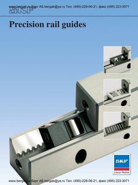
Precision rail guides
Precision rail guides
Precision rail guides

Create successful ePaper yourself
Turn your PDF publications into a flip-book with our unique Google optimized e-Paper software.
www.bergab.ru Берг АБ bergab@ya.ru Тел. (495)-228-06-21, факс (495) 223-3071<br />
<strong>Precision</strong> <strong>rail</strong> <strong>guides</strong><br />
www.bergab.ru Берг АБ bergab@ya.ru Тел. (495)-228-06-21, факс (495) 223-3071
www.bergab.ru Берг АБ bergab@ya.ru Тел. (495)-228-06-21, факс (495) 223-3071<br />
General<br />
SKF Group<br />
The SKF Group is an international<br />
industrial corporation owned by<br />
SKF Sweden AB. Founded in 1907,<br />
the company has some 39 000 employees,<br />
80 manufacturing sites and a<br />
sales network via its own sales companies,<br />
distributors and dealers<br />
covering 150 countries around the<br />
world. SKF is the world leader in the<br />
rolling bearing business.<br />
SKF Linear Motion<br />
SKF Linear Motion belongs to the<br />
SKF Group and is specialised in the<br />
manufacturing and sales of a wide<br />
range of high precision components,<br />
units and systems for linear movements,<br />
providing solutions for guiding,<br />
driving, actuation and positioning<br />
tasks. In addition, SKF Linear Motion<br />
also offers a large assortment of products<br />
which are in synergy to the linear<br />
motion range and are providing<br />
complete solutions for applications.<br />
SKF Linear Motion comprises<br />
4 product lines with 10 specialised<br />
sales companies in Europe and North<br />
America; additionally, product<br />
availability and product application<br />
support is provided world-wide by<br />
the international sales network of the<br />
SKF Group.<br />
A complete range from a single source for all<br />
linear motion functions.<br />
Guiding<br />
Driving<br />
Actuation<br />
Positioning<br />
www.bergab.ru Берг АБ bergab@ya.ru Тел. (495)-228-06-21, факс (495) 223-3071
Product review<br />
www.bergab.ru Берг АБ bergab@ya.ru Тел. (495)-228-06-21, факс (495) 223-3071<br />
4<br />
Product range<br />
5<br />
Technical information<br />
9<br />
Rail <strong>guides</strong> in kit packaging<br />
12<br />
LWR <strong>rail</strong> <strong>guides</strong><br />
14<br />
LWRE <strong>rail</strong> <strong>guides</strong><br />
20<br />
LWRE ACS <strong>rail</strong> <strong>guides</strong> with non-slip cage<br />
25<br />
LWRM/LWRV <strong>rail</strong> <strong>guides</strong><br />
29<br />
LWRPM/LWRPV <strong>rail</strong> <strong>guides</strong><br />
33<br />
LWM/LWV <strong>rail</strong> <strong>guides</strong><br />
37<br />
LWJ/LWS flat <strong>rail</strong> <strong>guides</strong><br />
41<br />
LZM Mini Slides<br />
42<br />
GCL Standard Slides<br />
www.bergab.ru Берг АБ bergab@ya.ru Тел. (495)-228-06-21, факс (495) 223-3071<br />
44
www.bergab.ru Берг АБ bergab@ya.ru Тел. (495)-228-06-21, факс (495) 223-3071<br />
SKF precision <strong>rail</strong> <strong>guides</strong><br />
Introduction<br />
As the world’s leading rolling bearing<br />
manufacturer, SKF supplies practically<br />
every type of bearing for rotational<br />
and linear motion.<br />
SKF is therefore in a position to<br />
meet almost any customer requirement<br />
both technically and economically.<br />
This catalogue covers the SKF<br />
range of precision <strong>rail</strong> <strong>guides</strong> and accessories.<br />
SKF precision <strong>rail</strong> <strong>guides</strong> are highly<br />
accurate products for linear motion<br />
and are therefore ideally suited for use<br />
in a wide variety of machine tools,<br />
machining centres, handling systems<br />
and special machinery as well as<br />
measuring and testing equipment.<br />
The “Modular Range” has introduced<br />
a new concept to the market,<br />
ensuring the internal interchangeability<br />
of all well-known guidance systems<br />
including the high capacity LWREtype<br />
<strong>rail</strong> <strong>guides</strong>. This matrix range of<br />
<strong>rail</strong> guide modules permits the individual<br />
selection of <strong>rail</strong>s and rolling elements.<br />
SKF precision <strong>rail</strong> <strong>guides</strong> are available<br />
in many different designs, sizes<br />
and standard lengths, incorporating<br />
ball, roller or needle roller assemblies<br />
and slide coating. They are supplied<br />
with the required accessories for attachment<br />
and sealing.<br />
The use of SKF precision <strong>rail</strong> <strong>guides</strong><br />
facilitates the construction of economical,<br />
clearance-free linear <strong>guides</strong> of<br />
practically any type and length, according<br />
to the building block principle.<br />
The characteristics of the <strong>guides</strong> include:<br />
– a constant, high degree of running<br />
accuracy<br />
– low-friction, stick-slip free operation<br />
– high speed of travel<br />
– low heat generation<br />
– low wear and high reliability<br />
– high stiffness<br />
– excellent load carrying capacity<br />
For applications that are characterised<br />
by high accelerations or short<br />
strokes of high frequency, SKF <strong>rail</strong><br />
<strong>guides</strong> with dry sliding coating are<br />
recommended.<br />
These <strong>rail</strong> <strong>guides</strong> are also suitable<br />
for machine tool applications where<br />
the good damping properties of the<br />
<strong>guides</strong> are of greater importance than<br />
the lower friction of the rolling element<br />
<strong>rail</strong> <strong>guides</strong>. For those applications<br />
where <strong>rail</strong> <strong>guides</strong> are unsuitable, for<br />
instance because of their limited travel,<br />
SKF can supply alternative forms<br />
of linear guidance systems.<br />
All fast-selling precision <strong>rail</strong> <strong>guides</strong><br />
are also available in convenient kit<br />
packaging. This ensures complete delivery<br />
of all single components including<br />
end pieces and screws.<br />
If you would like further details,<br />
please contact the SKF application<br />
engineering department. We will be<br />
pleased to provide the required information<br />
without obligation and at no<br />
cost, or to prepare a technical proposal.<br />
This catalogue brings together all<br />
the basic data which we consider to<br />
be of interest. For additional information<br />
we recommend the SKF technical<br />
handbook “Linear guide systems”,<br />
publication no. 4185, which contains<br />
sections on the selection, application,<br />
operational life, mounting and maintenance<br />
of SKF precision <strong>rail</strong> <strong>guides</strong>.<br />
For further specialised advice please<br />
contact your nearest SKF sales office.<br />
All information in this catalogue is<br />
based on 2004 design and manufacturing<br />
standards.<br />
Earlier publications, the data in<br />
which deviates from that given here,<br />
are rendered invalid.<br />
If there is a danger of cage-creep<br />
(in particular when the guide is<br />
mounted vertically), precision <strong>rail</strong><br />
<strong>guides</strong> of type LWRE-ACS (Anti-<br />
Creep System) are an obvious choice,<br />
as they will eliminate this problem.<br />
2<br />
www.bergab.ru Берг АБ bergab@ya.ru Тел. (495)-228-06-21, факс (495) 223-3071
www.bergab.ru Берг АБ bergab@ya.ru Тел. (495)-228-06-21, факс (495) 223-3071<br />
Contents<br />
Product review................................................................................................. 4<br />
Product range<br />
Modular Range .................................................................................................. 5<br />
Other products .................................................................................................. 8<br />
Technical data<br />
Accuracy of <strong>rail</strong> <strong>guides</strong> ...................................................................................... 9<br />
Grading of <strong>rail</strong> <strong>guides</strong> ........................................................................................ 10<br />
Accuracy of adjacent parts................................................................................ 11<br />
Selection of <strong>rail</strong> <strong>guides</strong> ...................................................................................... 11<br />
Rail <strong>guides</strong> in kit packaging............................................................................ 12<br />
Modular Range <strong>rail</strong> <strong>guides</strong><br />
Tables<br />
LWR <strong>rail</strong> <strong>guides</strong> with crossed roller and ball assemblies................................... 14<br />
LWRE <strong>rail</strong> <strong>guides</strong> with crossed roller assemblies .............................................. 20<br />
LWRE ACS <strong>rail</strong> <strong>guides</strong> with non-slip cage (Anti Creep System) ........................ 25<br />
LWRM/LWRV <strong>rail</strong> <strong>guides</strong> with needle roller assemblies .................................... 29<br />
LWRPM/LWRPV <strong>rail</strong> <strong>guides</strong> with dry sliding coating......................................... 33<br />
Other <strong>rail</strong> <strong>guides</strong><br />
Tables<br />
LWM/LWV <strong>rail</strong> <strong>guides</strong> with needle roller assemblies ......................................... 37<br />
LWJ/LWS flat <strong>rail</strong> <strong>guides</strong> with needle roller assemblies..................................... 41<br />
LZM Mini Slides................................................................................................. 42<br />
GCL Standard Slides......................................................................................... 44<br />
www.bergab.ru Берг АБ bergab@ya.ru Тел. (495)-228-06-21, факс (495) 223-3071<br />
3
www.bergab.ru Берг АБ bergab@ya.ru Тел. (495)-228-06-21, факс (495) 223-3071<br />
SKF precision <strong>rail</strong> <strong>guides</strong><br />
Product review<br />
SKF Modular Range <strong>rail</strong> <strong>guides</strong><br />
LWRPM/PV<br />
LWRM/V<br />
LWRE<br />
LWRE ACS<br />
LWR<br />
with ball<br />
assembly<br />
Non-slip cage<br />
of LWRE ACS<br />
LWR<br />
with roller<br />
assembly<br />
4<br />
www.bergab.ru Берг АБ bergab@ya.ru Тел. (495)-228-06-21, факс (495) 223-3071
www.bergab.ru Берг АБ bergab@ya.ru Тел. (495)-228-06-21, факс (495) 223-3071<br />
SKF Modular Range <strong>rail</strong> <strong>guides</strong><br />
The SKF Modular Range consists of a<br />
matrix range of <strong>rail</strong> guide modules<br />
that enables individual permutations<br />
of <strong>rail</strong>s and rolling element assemblies.<br />
Different requirements for the<br />
<strong>guides</strong> do not call for changes in the<br />
design or mechanical environment.<br />
The choice of appropriate <strong>rail</strong> <strong>guides</strong><br />
is determined solely by the mechanical<br />
conditions under which the guide<br />
system is to operate. These operating<br />
requirements are covered by six different<br />
models (fig 1) that may be defined<br />
as <strong>rail</strong> <strong>guides</strong> with:<br />
– crossed roller assemblies of the<br />
standard LWR series<br />
– ball assemblies of the LWRB series<br />
– crossed roller assemblies of the optimised<br />
LWRE series<br />
– crossed roller assemblies with nonslip<br />
cage to prevent cage-creep of<br />
the LWRE ACS series<br />
– needle roller assemblies of the<br />
LWRM/LWRV series and<br />
– slide coating of the LWRPM/LWRPV<br />
series<br />
The Modular Range of <strong>rail</strong> <strong>guides</strong><br />
The blue shaded areas in the chart indicate<br />
the sizes included in the Modular<br />
Range. Experience has shown that<br />
some 80 % of applications can be<br />
covered by these (fig 2).<br />
Market situation<br />
SKF Modular Range<br />
fig 2<br />
Contrary to the current lack of uniformity<br />
within the market, the standard,<br />
interchangeable guidance systems<br />
of the Modular Range cover almost<br />
the entire spectrum of <strong>rail</strong> guide<br />
applications. The choice of a specific<br />
rolling element or, for extreme conditions,<br />
of a slide coating, is determined<br />
only by the actual operating conditions<br />
(fig 5). Generally, any <strong>rail</strong> guide<br />
can be operated in the ‘clamped’ or<br />
‘floating’ mode. The design of the <strong>rail</strong><br />
<strong>guides</strong> does not impose any special<br />
space requirements.<br />
A x B<br />
Type<br />
Size<br />
8.5 x 4 12 x 6 18 x 8 22 x 11 25 x 12 31 x 15 44 x 22 58 x 28 71 x 36 83 x 40 110 x 55<br />
1 2 3 2211 4 6 9 12 15 18 24<br />
–<br />
–<br />
X<br />
–<br />
–<br />
X<br />
X<br />
O<br />
O<br />
O<br />
O<br />
–<br />
–<br />
X<br />
O<br />
X<br />
X<br />
X<br />
–<br />
–<br />
–<br />
–<br />
LWRE ACS<br />
LWRE ACS<br />
–<br />
–<br />
O<br />
O<br />
O O O – – – –<br />
–<br />
–<br />
–<br />
–<br />
–<br />
O<br />
O<br />
O<br />
O<br />
–<br />
–<br />
–<br />
–<br />
O<br />
–<br />
–<br />
O<br />
O<br />
O<br />
O<br />
–<br />
–<br />
X<br />
X<br />
–<br />
–<br />
–<br />
–<br />
–<br />
–<br />
–<br />
–<br />
–<br />
fig 1<br />
= Modular Range<br />
X = available ex-stock in standard lengths<br />
O = available to order<br />
– = not available<br />
www.bergab.ru Берг АБ bergab@ya.ru Тел. (495)-228-06-21, факс (495) 223-3071<br />
5
www.bergab.ru Берг АБ bergab@ya.ru Тел. (495)-228-06-21, факс (495) 223-3071<br />
SKF precision <strong>rail</strong> <strong>guides</strong><br />
Increased performance achievable<br />
without design modification<br />
The Modular System is based on the<br />
well-proven LWR design which covers<br />
a wide range of applications. The new<br />
optimised LWRE series offers either<br />
doubled stiffness and a load carrying<br />
capacity increased by a factor of five<br />
or, alternatively, for a given load carrying<br />
capacity, a 50 % reduction in<br />
bearing size compared with the standard<br />
LWR design (fig 3).<br />
LWR 12<br />
fig 3<br />
LWRE 6<br />
Complete range<br />
In order to further simplify the application<br />
of Modular Range <strong>rail</strong> <strong>guides</strong>, all<br />
<strong>guides</strong> within a given size range have<br />
the same external dimensions and<br />
thus fit the space requirements of<br />
most commercially available <strong>rail</strong><br />
<strong>guides</strong>. This results in a very wide<br />
choice in terms of load carrying capacity,<br />
stiffness and operating characteristics.<br />
From the economical point of view,<br />
the use of the optimised LWRE series<br />
offers a double advantage.<br />
Firstly (although the initial cost is<br />
slightly higher) the range of application<br />
is extended significantly as regards<br />
stiffness and load carrying capacity.<br />
It thus offers a far better<br />
price/performance ratio. Secondly,<br />
the replacement of other <strong>rail</strong> <strong>guides</strong>,<br />
including those supplied by other<br />
manufacturers and already installed,<br />
can be carried out with ease and in a<br />
minimum of time.<br />
Above all, where the user needs to<br />
increase machine performance, a unit<br />
with a higher load rating can be fitted.<br />
In-situ replacement is made easier by<br />
the fact that no new attachment holes<br />
or fixing devices are required when<br />
using <strong>rail</strong> <strong>guides</strong> of the Modular<br />
Range. An additional advantage is the<br />
worldwide availability through distributors,<br />
simply by quoting the appropriate<br />
catalogue number. The internal<br />
design of the LWRE series ensures increased<br />
operational life through even<br />
distribution of load. This results from<br />
the optimisation of the cross-section<br />
which permits the use of larger rolling<br />
elements. The new design leads to a<br />
significant improvement in the<br />
roller/raceway contact performance.<br />
An important additional benefit is the<br />
introduction of a practically maintenance-free<br />
cage made of POM that<br />
matches the stringent demands for<br />
long operational life of the rolling elements<br />
and maintains its dimensional<br />
stability up to +80 °C. The individual<br />
rollers are well covered and the space<br />
between the <strong>rail</strong>s is almost filled, thus<br />
providing good protection against<br />
contamination. A special characteristic<br />
of the LWAKE 3, 6 and 9 cages is<br />
that they consist of ‘snap-on’ elements<br />
and can be fitted together to<br />
the required length (fig 4). Conventional<br />
crossed roller cages have their<br />
rollers arranged alternately evenly<br />
spaced, so that only half the rollers in<br />
a preloaded guide are load-bearing<br />
while the remainder act as idlers. In<br />
the new LWRE cage these essentially<br />
unused rollers can be partially turned<br />
in the direction of the load. For this<br />
purpose each individual cage segment<br />
is designed to be turned through<br />
90° about the longitudinal axis. These<br />
are manual adjustments and no special<br />
instructions are required when ordering<br />
from the catalogue.<br />
LWAKE 4 crossed roller cages consist<br />
of roller segments that are assembled<br />
according to the length specified<br />
by the customer.<br />
Standard crossed<br />
roller configuration<br />
Optional configurations<br />
of LWAKE 3, 6, and<br />
9 cage segments<br />
fig 4<br />
6<br />
www.bergab.ru Берг АБ bergab@ya.ru Тел. (495)-228-06-21, факс (495) 223-3071
www.bergab.ru Берг АБ bergab@ya.ru Тел. (495)-228-06-21, факс (495) 223-3071<br />
fig 5<br />
LWRE<br />
Crossed<br />
roller<br />
LWR<br />
Crossed roller<br />
LWRE ACS<br />
LWR/LWRB series<br />
This basic series of the Modular<br />
Range covers a wide variety of <strong>rail</strong><br />
guide applications for limited travel.<br />
Where low friction is essential, ball<br />
cage assemblies are recommended.<br />
If, on the other hand, high load carrying<br />
capacity is the chief requirement,<br />
robust crossed roller assemblies are<br />
to be preferred. The LWR series is<br />
manufactured in nine sizes based on<br />
rolling element dimensions.<br />
LWRE series<br />
For a given load carrying capacity, the<br />
dimensions of the LWRE series are<br />
significantly less than those of the<br />
corresponding member of the LWR<br />
series.<br />
Thus, for instance, an LWRE 6 guide<br />
with a cage length of 100 mm has a<br />
greater load carrying capacity than a<br />
standard LWR 12. The LWR 12 measures<br />
58 x 28 mm whereas the LWRE<br />
6 measures only 31 x 15 mm (fig 1).<br />
LWR/LWRB<br />
Ball<br />
LWRPM/<br />
LWRPV<br />
Slide coating<br />
LWRM/<br />
LWRV<br />
Needle roller<br />
LWRE ACS series<br />
All <strong>rail</strong>s of the LWRE series are also<br />
available with ACS, a special system<br />
to prevent “cage-creep”. These <strong>rail</strong>s<br />
are used where cage-creep occurs<br />
due to high acceleration, uneven preloading<br />
or load distribution as well as<br />
jerky running or direction-dependent<br />
speeds of travel.<br />
LWRM/LWRV series<br />
These <strong>guides</strong> are used principally<br />
where high load carrying capacity is<br />
called for in combination with high<br />
stiffness, for instance on grinding machines.<br />
This series is fitted with needle<br />
roller and cage assemblies consisting<br />
of two rows of needle rollers at<br />
right angles to each other.<br />
LWRPM/LWRPV series<br />
Where extremely short strokes of high<br />
frequency occur, this special series<br />
with slide coating is an essential alternative<br />
to those with rolling element<br />
assemblies. In the case of balls or<br />
rollers subjected to high transverse<br />
acceleration, pitting of the tracks may<br />
occur as a result of the unfavourable<br />
tribological conditions. Sliding <strong>rail</strong><br />
<strong>guides</strong> are preferred in such circumstances.<br />
The coating material is based on<br />
PTFE and is bonded on to the unhardened<br />
LWRPM <strong>rail</strong> and then ground to<br />
the correct dimension.<br />
This wear-resistant material combination<br />
is characterised by its stickslip-free,<br />
vibration-damping running<br />
properties, at the same time offering<br />
excellent stiffness and emergency<br />
running properties. These guide <strong>rail</strong>s<br />
are largely insensitive to contamination,<br />
coolants and lubricants.<br />
Materials and precision<br />
The <strong>rail</strong>s of the Modular Range <strong>guides</strong><br />
are manufactured from tool steel<br />
90 MnCrV 8 with a hardness of between<br />
58 and 64 HRC. If required by<br />
the application, the <strong>rail</strong>s can also be<br />
supplied in special stainless steel, e.g.<br />
X 90 CrMoV 18 in all standard dimensions.<br />
All rolling elements are made<br />
from carbon chromium steel 100 Cr 6<br />
with a hardness of between 58 and<br />
64 HRC. The parallelism of the raceways<br />
is divided into three classes.<br />
Class P10, with a maximum deviation<br />
of 10 µm per 1000 mm length, meets<br />
most of the demands for normal machinery.<br />
Where greater precision is required,<br />
tolerance classes P5 and P2<br />
are also available.<br />
The assortment is complemented<br />
by various accessories specially designed<br />
for the Modular Range of <strong>rail</strong><br />
<strong>guides</strong>. These include end pieces with<br />
or without wipers as well as special<br />
attachment screws.<br />
www.bergab.ru Берг АБ bergab@ya.ru Тел. (495)-228-06-21, факс (495) 223-3071<br />
7
www.bergab.ru Берг АБ bergab@ya.ru Тел. (495)-228-06-21, факс (495) 223-3071<br />
SKF precision <strong>rail</strong> <strong>guides</strong><br />
Other products<br />
In addition to the Modular Range, the<br />
selection of SKF products also includes<br />
a wide variety of <strong>rail</strong> <strong>guides</strong><br />
and rolling elements.<br />
LWM/LWV <strong>rail</strong> <strong>guides</strong><br />
(see table on pages 38-40)<br />
LWM/LWV <strong>rail</strong> <strong>guides</strong> differ from the<br />
LWRM/LWRV <strong>guides</strong> of the Modular<br />
Range only in their external dimensions.<br />
Their internal geometry is identical<br />
and the same needle roller assemblies<br />
are therefore used.<br />
In contrast to LWRM/LWRV (two<br />
series), the LWM/LWV <strong>guides</strong> comprise<br />
6 series up to a size of A x B =<br />
80 mm x 50 mm. LWM/LWV <strong>rail</strong><br />
<strong>guides</strong> are supplied as standard with<br />
holes of type 15, namely through<br />
holes with counterbore. If for design<br />
reasons it is necessary to screw both<br />
<strong>rail</strong>s from the same side, then one of<br />
the <strong>rail</strong>s should have holes of type 13,<br />
i.e. with thread insert.<br />
LWML <strong>rail</strong> <strong>guides</strong><br />
(no table)<br />
The LWML <strong>rail</strong> guide consists of a<br />
modified LWM <strong>rail</strong> guide with the addition<br />
of an adjustment wedge. Used<br />
in conjunction with an LWV guide and<br />
a needle roller assembly this provides<br />
an adjustable guide unit. The inclination<br />
of the wedge surface is 1,5 % so<br />
that a displacement of the wedge by<br />
1 mm brings about a 15 µm alteration<br />
in the height.<br />
LWML <strong>rail</strong> <strong>guides</strong> are supplied as<br />
standard with holes of type 15, i.e.<br />
through holes with counterbore. If required<br />
holes of type 13, i.e. with<br />
thread insert, are also available.<br />
LWML <strong>rail</strong> <strong>guides</strong> can be supplied<br />
to tolerance classes P10 and P5.<br />
These <strong>guides</strong>, as well as the appropriate<br />
needle roller assemblies and<br />
end pieces, are made to order.<br />
Because of the many permutations<br />
available, each part of an LWML/LWV<br />
<strong>rail</strong> guide must be ordered separately,<br />
e.g.:<br />
It should also be stated whether<br />
the holes should comprise right-hand<br />
or left-hand threads.<br />
LWN/LWO <strong>rail</strong> <strong>guides</strong><br />
(no table)<br />
LWN/LWO <strong>rail</strong> <strong>guides</strong> differ from the<br />
LWM/LWV <strong>rail</strong> <strong>guides</strong> only in height,<br />
width and attachment holes. The internal<br />
geometry is identical to that of<br />
the LWM/LWV <strong>guides</strong>, i.e. they have<br />
the same load rating.<br />
LWN/LWO <strong>rail</strong> <strong>guides</strong> are available<br />
in tolerance classes P10, P5 and P2<br />
to order.<br />
LWW/LWZ flat <strong>rail</strong> <strong>guides</strong><br />
(no table)<br />
LWW/LWZ flat <strong>rail</strong> <strong>guides</strong> are used in<br />
conjunction with LWR <strong>rail</strong> <strong>guides</strong> for<br />
incorporation in floating slides.<br />
LWW/LWZ flat <strong>rail</strong> <strong>guides</strong> and the appropriate<br />
rolling element assemblies<br />
and end pieces are available to order.<br />
LWJ/LWS flat <strong>rail</strong> <strong>guides</strong><br />
(no table)<br />
LWJ/LWS flat <strong>rail</strong> <strong>guides</strong> are used in<br />
conjunction with LWRM/LWRV,<br />
LWM/LWV or LWN/LWO <strong>rail</strong> <strong>guides</strong> as<br />
non-locating linear <strong>guides</strong>. They are<br />
incorporated in floating slides.<br />
LWJ/LWS flat <strong>rail</strong> <strong>guides</strong> as well as<br />
the appropriate rolling element assemblies<br />
and end pieces are available<br />
to order.<br />
Special <strong>rail</strong> <strong>guides</strong> and recirculating<br />
roller assemblies<br />
In addition to the standard <strong>rail</strong> <strong>guides</strong><br />
included in this catalogue, SKF also<br />
manufactures flat <strong>rail</strong> <strong>guides</strong> with recirculating<br />
roller assemblies as well as<br />
special <strong>rail</strong> <strong>guides</strong> to customer drawings<br />
for such applications as machine<br />
tools, handling systems and robotics.<br />
Further information on these special<br />
versions and their availability will<br />
be supplied on request.<br />
1 <strong>rail</strong> LWML 55200400<br />
1 <strong>rail</strong> LWM 40200400<br />
2 <strong>rail</strong>s LWV 40200400<br />
2 end pieces LWEML 4020<br />
2 end pieces LWEM 4020<br />
8<br />
www.bergab.ru Берг АБ bergab@ya.ru Тел. (495)-228-06-21, факс (495) 223-3071
www.bergab.ru Берг АБ bergab@ya.ru Тел. (495)-228-06-21, факс (495) 223-3071<br />
Technische Hinweise<br />
<strong>Precision</strong> of <strong>rail</strong> <strong>guides</strong><br />
All SKF precision <strong>rail</strong> <strong>guides</strong>, regardless<br />
of type, are manufactured to the<br />
same tolerances indicated below.<br />
Raceway accuracy<br />
In order to meet the different requirements<br />
regarding the precision of linear<br />
bearing arrangements, the <strong>rail</strong>s are<br />
produced in three different tolerance<br />
classes. These are classified according<br />
to the parallelism between the<br />
raceways and the support surfaces A<br />
and B (fig 6).<br />
P10<br />
Tolerance class normal. This meets<br />
the requirements of general engineering<br />
applications. The deviation from<br />
parallelism for a 1000 mm long <strong>rail</strong> is<br />
approximately 10 µm. See also adjacent<br />
table 1.<br />
P5<br />
This satisfies the demands normally<br />
made on the running accuracy for machine<br />
tool applications. The deviation<br />
from parallelism for a 1000 mm long<br />
<strong>rail</strong> is 5 µm maximum. See also adjacent<br />
table 1.<br />
Dimensional accuracy<br />
SKF precision <strong>rail</strong> <strong>guides</strong> with limited<br />
travel are produced to the following<br />
tolerances (figs 7 and 8):<br />
Width A: 0/-0,3mm<br />
Abutment height<br />
T = B 1 + B 2 ± 0,02 mm<br />
Rail height B: 0/-0,2 mm<br />
Rail length L: L ≤ 300 ± 0,3<br />
L > 300 ± 0,001 · L [mm]<br />
For <strong>rail</strong>s composed of two or more<br />
sections the tolerance for the total<br />
length is ± 2 mm.<br />
SKF precision <strong>rail</strong> <strong>guides</strong> for recirculating<br />
roller assemblies are produced<br />
to the following tolerances:<br />
Width A:<br />
Height A:<br />
Length L:<br />
0/+0,1 mm<br />
0/+0,1 mm<br />
0/+0,002 · L mm<br />
P2<br />
Accuracy for the most exacting demands.<br />
Rails made to this tolerance<br />
class should only be used when the<br />
associated components are made to<br />
a correspondingly high degree of precision.<br />
Rails to tolerance class P2 will<br />
be manufactured by SKF to special<br />
order. See also table 1.<br />
If no mention is made of the requisite<br />
accuracy on the order, <strong>rail</strong>s with<br />
normal P10 tolerances will be supplied.<br />
fig 6<br />
Permissible deviation in parallelism between reference planes A and B<br />
Rail length<br />
Tolerance class<br />
from to P10 P5 P2<br />
mm µm<br />
100 2 1 1<br />
100 200 3 2 1<br />
200 300 4 2 1<br />
300 400 5 2 2<br />
400 500 6 3 2<br />
500 600 6 3 2<br />
600 700 7 4 2<br />
700 800 8 4 2<br />
800 900 8 5 2<br />
900 1000 9 5 2<br />
1000 1200 10 6 3<br />
1200 1400 11 6 3<br />
1400 1600 12 7 3<br />
Table 1<br />
www.bergab.ru Берг АБ bergab@ya.ru Тел. (495)-228-06-21, факс (495) 223-3071<br />
9
www.bergab.ru Берг АБ bergab@ya.ru Тел. (495)-228-06-21, факс (495) 223-3071<br />
SKF precision <strong>rail</strong> <strong>guides</strong><br />
Grading<br />
<strong>Precision</strong> <strong>rail</strong> <strong>guides</strong> with limited travel<br />
are generally mounted in pairs. In order<br />
to obtain the same assembly<br />
height T (fig 7), the <strong>rail</strong>s are graded<br />
and supplied in pairs.<br />
This ensures that any two similar<br />
<strong>rail</strong> <strong>guides</strong> in a system will have the<br />
same height. The grading accuracy is<br />
always within the appropriate tolerance<br />
class for the parallelism.<br />
If two or more rolling element assemblies<br />
are to be mounted immediately<br />
behind each other in a <strong>rail</strong> guide,<br />
the rolling elements must have the<br />
same tolerance grade. On request,<br />
graded rolling element assemblies<br />
can be supplied.<br />
Rails of the same profile for recirculating<br />
roller assemblies, which are to<br />
be mounted immediately adjacent to<br />
each other or immediately behind<br />
each other should be ordered in graded<br />
condition. Depending on their<br />
type, they will be graded in height or<br />
in height and width and delivered as a<br />
single package.<br />
Rail guide sets are always matched<br />
so that it is not necessary to request<br />
this when ordering.<br />
Tolerance of distance between<br />
attachment holes<br />
The maximum deviation in the distance<br />
between the attachment holes<br />
measured from centre to centre is<br />
± 0,8 ‰ of the <strong>rail</strong> length L for onepiece<br />
<strong>rail</strong>s (fig 8). Where the <strong>rail</strong> consists<br />
of several sections, the tolerance<br />
is also ± 0,8 ‰, related to the length<br />
of the longest section. Rails having<br />
tighter tolerances for the distance between<br />
the holes can be supplied on<br />
request.<br />
Marking of matched sets<br />
Matched components are marked<br />
with consecutive numbers as indicated<br />
in fig 8a.<br />
fig 7<br />
fig 8<br />
fig 8 a<br />
(=B 1 +B 2 )<br />
10<br />
www.bergab.ru Берг АБ bergab@ya.ru Тел. (495)-228-06-21, факс (495) 223-3071
www.bergab.ru Берг АБ bergab@ya.ru Тел. (495)-228-06-21, факс (495) 223-3071<br />
Accuracy of adjacent components<br />
An important criterion for the correct<br />
performance of a <strong>rail</strong> guide system is<br />
the accuracy of the associated components.<br />
The higher the demands for<br />
accuracy of guidance and for smooth,<br />
easy operation, the greater the attention<br />
which must be paid to the accuracy<br />
of form and position of the associated<br />
components. Generally the<br />
same accuracy requirements should<br />
be applied to these components as to<br />
the <strong>rail</strong> <strong>guides</strong> themselves. The adjacent<br />
table shows the values, for each<br />
tolerance class, of the surface roughness,<br />
perpendicularity and parallelism<br />
of the adjacent components.<br />
To assure an even load distribution<br />
over the roller length, the maximum<br />
difference in height of the supports for<br />
a <strong>rail</strong> guide should not exceed<br />
∆h = 0,1 · B 1<br />
where<br />
∆h = maximum height deviation, µm<br />
B 1 = mean distance between two<br />
<strong>rail</strong> <strong>guides</strong>, mm<br />
To obtain good support for the <strong>rail</strong>s<br />
on the associated components, the<br />
attachment holes should be carefully<br />
deburred (figs 9 and 10).<br />
Selection of <strong>rail</strong> <strong>guides</strong><br />
When selecting a <strong>rail</strong> guide, the length<br />
of travel, load carrying capacity, requisite<br />
life and stiffness are the most decisive<br />
factors. Other important parameters<br />
include the requisite speed of<br />
travel, lubrication, operating temperatures,<br />
ease of movement, environmental<br />
influences and certain design<br />
constraints, for instance whether<br />
“clamped” or “floating” guidance is<br />
required. For additional information<br />
we recommend the SKF technical<br />
handbook publication no. 4185.<br />
The selection of the size and length<br />
of the rolling element assemblies is<br />
mainly determined by the required load<br />
carrying capacity, life and stiffness.<br />
For light, centrally acting loads and<br />
moderate demands for speed of travel,<br />
it is possible to use practically all<br />
the types of <strong>guides</strong> listed in this catalogue.<br />
However, technical and economic<br />
reasons often dictate the<br />
choice of the most appropriate model<br />
for a given application.<br />
fig 9<br />
Accuracy of form of support surfaces<br />
Characteristic Symbol for Permissible<br />
deviation of form<br />
Charac- Tolerance Dimensions Tolerance class<br />
teristic zone<br />
P10 P5 P2<br />
Roughness R a a µm 1,6 0,8 0,2<br />
Perpendicularity ⊥ t 1 /t 2 µm/mm 0,3 0,3 0,3<br />
Parallelism ⁄⁄ t 3 /T 4 µm depending on the<br />
guide length L (mm)<br />
3 2 1 200<br />
6 4 2 500<br />
10 6 3 1000<br />
fig 10<br />
The length of a <strong>rail</strong> guide and of the<br />
individual <strong>rail</strong>s is mainly determined<br />
by the travel as well as the length of<br />
the rolling element assemblies, which<br />
depends on the requisite load carrying<br />
capacity and life.<br />
The following relationships serve as<br />
guidelines for determining the length<br />
of <strong>rail</strong> <strong>guides</strong> and rolling element assemblies:<br />
For a given stroke:<br />
Cage length = stroke, at least<br />
For a given cage length:<br />
Rail length = cage length<br />
+ 0,5 x stroke<br />
For a given <strong>rail</strong> length and stroke, the<br />
cage length is is obtained from:<br />
Cage length = Rail length<br />
– 0,5 x stroke<br />
www.bergab.ru Берг АБ bergab@ya.ru Тел. (495)-228-06-21, факс (495) 223-3071<br />
11
www.bergab.ru Берг АБ bergab@ya.ru Тел. (495)-228-06-21, факс (495) 223-3071<br />
SKF precision <strong>rail</strong> <strong>guides</strong><br />
SKF precision <strong>rail</strong> <strong>guides</strong> in kit packaging<br />
Rail <strong>guides</strong> in kit packaging<br />
Kit packaging is a new service offered<br />
by SKF. Each kit consists of a fourpiece<br />
<strong>rail</strong> guide set, 2 cages and<br />
8 end pieces.<br />
Advantages of <strong>rail</strong> guide kits<br />
– all required components are supplied<br />
in ready-to-mount sets and<br />
can be ordered via one single order<br />
number<br />
– for enhanced ease of mounting, all<br />
parts can now be supplied directly<br />
to the machine on site<br />
– cage length easily adjustable<br />
– environmentally compatible packaging<br />
that can be returned free of<br />
charge and directed to the recycling<br />
process<br />
– most kits available ex stock<br />
– also available with ACS for the effective<br />
prevention of cage-creep<br />
Certified in accordance with ISO<br />
14001, SKF Linear Motion and the entire<br />
SKF Group attach great importance<br />
to environmental protection.<br />
Hence as a matter of course, SKF kit<br />
packagings can be returned free of<br />
charge and are directed to the recycling<br />
process. This makes them both<br />
a convenient and an environmentallyfriendly<br />
packaging solution.<br />
LWR <strong>rail</strong> <strong>guides</strong> in kit packaging<br />
Designation Load ratings Stroke Type of <strong>rail</strong> Type of cage<br />
dyn. stat. 4 pieces 2 pieces<br />
C C 0 min. max.<br />
N<br />
mm<br />
LWR 3050 Kit 999 1120 26 33 LWR 3050 LWAK 3x7<br />
LWR 3075 Kit 1422 1760 36 50 LWR 3075 LWAK 3x11<br />
LWR 3100 Kit 1811 2400 46 67 LWR 3100 LWAK 3x15<br />
LWR 3125 Kit 2088 2880 66 83 LWR 3125 LWAK 3x18<br />
LWR 3150 Kit 2442 3520 76 100 LWR 3150 LWAK 3x22<br />
LWR 3175 Kit 2781 4160 86 117 LWR 3175 LWAK 3x26<br />
LWR 3200 Kit 3110 4800 96 133 LWR 3200 LWAK 3x30<br />
including 8 end pieces LWERA 3<br />
LWR 6100 Kit 4915 5440 50 67 LWR 6100 LWAL 6x8<br />
LWR 6150 Kit 6744 8160 78 100 LWR 6150 LWAL 6x12<br />
LWR 6200 Kit 8441 10880 106 133 LWR 6200 LWAL 6x16<br />
LWR 6250 Kit 10045 13600 134 167 LWR 6250 LWAL 6x20<br />
LWR 6300 Kit 11955 17000 144 200 LWR 6300 LWAL 6x25<br />
LWR 6350 Kit 13422 19720 172 233 LWR 6350 LWAL 6x29<br />
LWR 6400 Kit 14846 22440 200 267 LWR 6400 LWAL 6x33<br />
including 8 end pieces LWERA 6<br />
12<br />
www.bergab.ru Берг АБ bergab@ya.ru Тел. (495)-228-06-21, факс (495) 223-3071
www.bergab.ru LWRE <strong>rail</strong> <strong>guides</strong> Берг in kit АБ packaging bergab@ya.ru Тел. (495)-228-06-21, факс (495) 223-3071<br />
Designation Load ratings Stroke Type of <strong>rail</strong> Type of cage<br />
dyn. stat. 4 pieces 2 pieces<br />
C C 0 min. max.<br />
N<br />
mm<br />
LWRE 3050 Kit 4230 5100 25 33 LWRE 3050 LWAKE 3x6<br />
LWRE 3075 Kit 5803 7650 38 50 LWRE 3075 LWAKE 3x9<br />
LWRE 3100 Kit 7263 10200 50 67 LWRE 3100 LWAKE 3x12<br />
LWRE 3125 Kit 8644 12750 63 83 LWRE 3125 LWAKE 3x15<br />
LWRE 3150 Kit 9964 15300 75 100 LWRE 3150 LWAKE 3x18<br />
LWRE 3175 Kit 11238 17850 88 117 LWRE 3175 LWAKE 3x21<br />
LWRE 3200 Kit 12471 20400 100 133 LWRE 3200 LWAKE 3x24<br />
including 8 end pieces LWERE 3<br />
LWRE 4100 Kit 17300 20800 39 67 LWRE 4100 LWAKE 4x10<br />
LWRE 4150 Kit 23735 31200 62 100 LWRE 4150 LWAKE 4x15<br />
LWRE 4200 Kit 28541 39520 95 133 LWRE 4200 LWAKE 4x19<br />
LWRE 4250 Kit 34246 49920 118 167 LWRE 4250 LWAKE 4x24<br />
LWRE 4300 Kit 38622 58240 152 200 LWRE 4300 LWAKE 4x28<br />
LWRE 4350 Kit 43902 68640 169 233 LWRE 4350 LWAKE 4x33<br />
LWRE 4400 Kit 49009 79040 192 267 LWRE 4400 LWAKE 4x38<br />
including 8 end pieces LWERE 3<br />
LWRE 6100 Kit 25743 27300 46 67 LWRE 6100 LWAKE 6x7<br />
LWRE 6150 Kit 34000 39000 80 100 LWRE 6150 LWAKE 6x10<br />
LWRE 6200 Kit 44204 54600 92 133 LWRE 6200 LWAKE 6x14<br />
LWRE 6250 Kit 51431 66300 126 167 LWRE 6250 LWAKE 6x17<br />
LWRE 6300 Kit 58382 78000 160 200 LWRE 6300 LWAKE 6x20<br />
LWRE 6350 Kit 67304 93600 172 233 LWRE 6350 LWAKE 6x24<br />
LWRE 6400 Kit 73781 105300 206 267 LWRE 6400 LWAKE 6x27<br />
including 8 end pieces LWERE 6<br />
LWRE ACS <strong>rail</strong> <strong>guides</strong> in kit packaging (supplied to order)<br />
Designation Load ratings Stroke Type of <strong>rail</strong> Type of cage<br />
dyn. stat. 4 pieces 2 pieces<br />
C C 0 min. max<br />
N<br />
mm<br />
LWRE 3050 ACS - Kit 4230 5100 20 33 LWRE 3050 ACS LWAKE 3 x 6 ACS<br />
LWRE 3075 ACS - Kit 5294 6800 30 50 LWRE 3075 ACS LWAKE 3 x 6 ACS<br />
LWRE 3100 ACS - Kit 6300 8500 45 67 LWRE 3100 ACS LWAKE 3 x 10 ACS<br />
LWRE 3125 ACS - Kit 7731 11050 62 83 LWRE 3125 ACS LWAKE 3 x 13 ACS<br />
LWRE 3150 ACS - Kit 9090 13600 79 100 LWRE 3150 ACS LWAKE 3 x 16 ACS<br />
LWRE 3175 ACS - Kit 9964 15300 94 117 LWRE 3175 ACS LWAKE 3 x 18 ACS<br />
LWRE 3200 ACS - Kit 11653 18700 100 133 LWRE 3200 ACS LWAKE 3 x 22 ACS<br />
including 8 end pieces LWERE 3<br />
LWRE 4100 ACS - Kit 14536 16640 40 67 LWRE 4100 ACS LWAKE 4 x 8 ACS<br />
LWRE 4150 ACS - Kit 19944 24960 79 100 LWRE 4150 ACS LWAKE 4 x 12 ACS<br />
LWRE 4200 ACS - Kit 26170 35360 96 133 LWRE 4200 ACS LWAKE 4 x 17 ACS<br />
LWRE 4250 ACS - Kit 30859 43680 129 167 LWRE 4250 ACS LWAKE 4 x 21 ACS<br />
LWRE 4300 ACS - Kit 36452 54080 152 200 LWRE 4300 ACS LWAKE 4 x 26 ACS<br />
LWRE 4350 ACS - Kit 41813 64480 175 233 LWRE 4350 ACS LWAKE 4 x 31 ACS<br />
LWRE 4400 ACS - Kit 45964 72800 203 267 LWRE 4400 ACS LWAKE 4 x 35 ACS<br />
including 8 end pieces LWERE 4<br />
LWRE 6100 ACS - Kit 22826 23400 37 67 LWRE 6100 ACS LWAKE 6 x 6 ACS<br />
LWRE 6150 ACS - Kit 31318 35100 71 100 LWRE 6150 ACS LWAKE 6 x 9 ACS<br />
LWRE 6200 ACS - Kit 39196 46800 105 133 LWRE 6200 ACS LWAKE 6 x 12 ACS<br />
LWRE 6250 ACS - Kit 49056 62400 117 167 LWRE 6250 ACS LWAKE 6 x 16 ACS<br />
LWRE 6300 ACS - Kit 56093 74100 151 200 LWRE 6300 ACS LWAKE 6 x 19 ACS<br />
LWRE 6350 ACS - Kit 65107 89700 163 233 LWRE 6350 ACS LWAKE 6 x 23 ACS<br />
LWRE 6400 ACS - Kit 71640 101400 197 267 LWRE 6400 ACS LWAKE 6 x 26 ACS<br />
including 8 end pieces LWERE 6<br />
www.bergab.ru Берг АБ bergab@ya.ru Тел. (495)-228-06-21, факс (495) 223-3071<br />
13
www.bergab.ru Берг АБ bergab@ya.ru Тел. (495)-228-06-21, факс (495) 223-3071<br />
SKF precision <strong>rail</strong> <strong>guides</strong><br />
LWR <strong>rail</strong> <strong>guides</strong><br />
LWR <strong>rail</strong> <strong>guides</strong> are well-proven, limited-travel<br />
linear <strong>guides</strong> used in numerous<br />
applications. They consist of<br />
two identical <strong>rail</strong>s between which<br />
crossed roller assemblies or ball assemblies<br />
are inserted, depending on<br />
the respective application.<br />
LWR <strong>rail</strong> <strong>guides</strong> with crossed roller<br />
assemblies are robust linear bearings<br />
with high load carrying capacity. Their<br />
special characteristics make them<br />
suitable for a large proportion of linear<br />
bearing arrangements with limited<br />
travel.<br />
LWR <strong>rail</strong> <strong>guides</strong> with ball assembly<br />
can be used to advantage where<br />
loads are light and/or easy running is<br />
required.<br />
Rail <strong>guides</strong> with a length greater<br />
than 1200 mm are supplied in sections.<br />
Because of the many permutations<br />
available, each part of an LWR <strong>rail</strong><br />
guide must be ordered separately,<br />
e. g:<br />
4 <strong>rail</strong>s LWR 90600<br />
2 crossed roller assemblies<br />
LWAL 9x25<br />
8 end pieces LWERA 9<br />
Ordering<br />
To facilitate the order routine, <strong>rail</strong><br />
guide sets can also be ordered in kit<br />
packaging (see pages 12-13).<br />
14<br />
www.bergab.ru Берг АБ bergab@ya.ru Тел. (495)-228-06-21, факс (495) 223-3071
www.bergab.ru Берг АБ bergab@ya.ru Тел. (495)-228-06-21, факс (495) 223-3071<br />
Ball and crossed roller assemblies<br />
for LWR <strong>rail</strong> <strong>guides</strong><br />
Ball assemblies<br />
Where moderate loads are to be supported<br />
by a <strong>rail</strong> guide and greater priority<br />
is given to smooth operation and<br />
low friction, the use of ball assemblies<br />
is recommended.<br />
LWJK ball assemblies are provided<br />
with a plastic ball-retaining cage.<br />
These are available for sizes 1 and 2.<br />
Crossed roller assemblies<br />
Where greater stiffness is required,<br />
crossed roller assemblies are recommended.<br />
Various cage types are available,<br />
depending on the size of the<br />
rollers.<br />
external and attachment dimensions<br />
correspond with those of the LWR<br />
series.<br />
LWR <strong>rail</strong> <strong>guides</strong> are available in a total<br />
of nine sizes. The “Modular Range”<br />
includes sizes 3, 6 and 9 which, according<br />
to experience, cover 80 % of<br />
the normal market requirements. To<br />
enable prompt delivery from stock,<br />
certain standard <strong>rail</strong> lengths have<br />
been defined.<br />
SKF Modular Range <strong>rail</strong> <strong>guides</strong> are<br />
specially highlighted in the tables. For<br />
further information, please refer to<br />
pages 5 to 7.<br />
LWAK crossed roller assemblies are<br />
fitted as standard for size 3 with a<br />
plastic cage to retain the cylindrical<br />
rollers.<br />
LWAL crossed roller assemblies are<br />
available in sizes 6 to 12 with aluminium<br />
cages. They comprise retained<br />
rollers.<br />
End pieces for LWR <strong>rail</strong> <strong>guides</strong><br />
End pieces prevent the drift of the<br />
cage away from the loaded zone.<br />
LWERA end pieces fulfil these requirements<br />
in low-load conditions<br />
combined with horizontal mounting.<br />
Attachment screws for<br />
LWR <strong>rail</strong> <strong>guides</strong><br />
In particular in the case of long <strong>rail</strong><br />
<strong>guides</strong>, heat treatment can lead to<br />
thermal expansion which will also influence<br />
the distance between the tap<br />
holes. Special attachment screws<br />
compensate for this longitudinal expansion.<br />
LWGD special attachment screws<br />
can be used for all <strong>rail</strong>s within the<br />
Modular Range.<br />
SKF Modular Range<br />
The LWR <strong>rail</strong> <strong>guides</strong> form the basis for<br />
the whole Modular Range system. All<br />
<strong>guides</strong> with designations commencing<br />
LWR... included in this catalogue<br />
are interchangeable with each other<br />
within a given dimension series. All<br />
www.bergab.ru Берг АБ bergab@ya.ru Тел. (495)-228-06-21, факс (495) 223-3071<br />
15
www.bergab.ru Берг АБ bergab@ya.ru Тел. (495)-228-06-21, факс (495) 223-3071<br />
SKF precision <strong>rail</strong> <strong>guides</strong><br />
LWR<br />
Rail <strong>guides</strong><br />
LWR 3 - LWR 12 LWRB 1 + 2<br />
Designation Designation Dimensions:<br />
new System Mounting holes End face holes Available lenghts<br />
A B A 1 D w J J 1 J 2 G G 1 N N 1 J 3 G 2 G 3 L 1)<br />
mm 020 030 040 045 050 060<br />
LWRB 1 LW 0804 8,5 4 3,9 1,6 10 5 1,8 M2 1,65 3 1,4 1,9 M1,6 2<br />
LWRB 2 LW 1206 12 6 5,5 2 15 7,5 2,5 M3 2,55 4,4 2 2,7 M2,5 3<br />
• •<br />
• • •<br />
• •<br />
•<br />
Designation<br />
Dimensions:<br />
System Mounting holes End face holes Available lenghts<br />
A B A 1 D w J J 1 J 2 G G 1 N N 1 J 3 G 2 G 3 L 1)<br />
mm 050 075 100 125 150 175 200 225 250<br />
LWR 3 18 8 8,2 3 25 12,5 3,5 M4 3,3 6 3,2 4 M3 6<br />
LWR 6 31 15 13,9 6 50 25 6 M6 5,2 9,5 5,2 7 M5 9<br />
LWR 9 44 22 19,7 9 100 50 9 M8 6,8 10,5 6,2 10 M6 9<br />
LWR 12 58 28 25,9 12 100 50 12 M10 8,5 13,5 8,2 13 M8 12<br />
• •<br />
• •<br />
• º<br />
• • • º •<br />
• • •<br />
•<br />
º<br />
1)<br />
Other lengths (LWR 15, 18 and 24) available to special order<br />
16<br />
www.bergab.ru Берг АБ bergab@ya.ru Тел. (495)-228-06-21, факс (495) 223-3071
www.bergab.ru Берг АБ bergab@ya.ru Тел. (495)-228-06-21, факс (495) 223-3071<br />
Ball and crossed roller assemblies End pieces Special attachment screws<br />
LWJK<br />
LWERA 1+2<br />
LWAK<br />
LWERA 3-12<br />
LWGD<br />
LWAL<br />
Ball and crossed roller assemblies End pieces 1) Special<br />
attachment<br />
screws<br />
070 075 080 090 100 105 120 135 150 LWJK LWERA LWGD<br />
º º º º<br />
•<br />
•<br />
• • • •<br />
•<br />
•<br />
º<br />
º<br />
Ball and crossed roller assemblies End pieces 1) Special<br />
attachment<br />
screws<br />
275 300 350 400 450 500 550 600 650 700 800 900 1000 LWAK LWAL LWERA LWGD<br />
º •<br />
•<br />
•<br />
•<br />
• • • • • º º º º<br />
•<br />
•<br />
•<br />
• • • •<br />
•<br />
• º º º •<br />
•<br />
•<br />
•<br />
•<br />
•<br />
º º º º º<br />
º º<br />
º<br />
º<br />
º<br />
º<br />
•<br />
•<br />
º<br />
SKF Modular Range.<br />
Preferred range, prompt delivery<br />
Prompt delivery<br />
Available to order<br />
Example: 4 LWR 3100 or 4 LWR 90200<br />
2 LWAK 3 x 17 2 LWAL 9x10<br />
8 LWERA 3 4 LWERA 9<br />
www.bergab.ru Берг АБ bergab@ya.ru Тел. (495)-228-06-21, факс (495) 223-3071<br />
17
www.bergab.ru Берг АБ bergab@ya.ru Тел. (495)-228-06-21, факс (495) 223-3071<br />
SKF precision <strong>rail</strong> <strong>guides</strong><br />
Accessories for LWR <strong>rail</strong> <strong>guides</strong><br />
Ball and crossed roller assemblies<br />
LWJK<br />
LWAL<br />
LWAK<br />
For description and data relating<br />
to rolling element assemblies, see page 15<br />
Designation 1) Dimensions Load ratings Appropriate<br />
for 10 rolling elements <strong>rail</strong> guide<br />
dynamic static<br />
D w U U 1 t t 1 C C 0<br />
mm<br />
LWJK 1 1,6 3,5 0,5 2,2 1,0 410 580 LWRB 1<br />
LWJK 2 2 5 0,75 3,0 1,5 640 720 LWRB 2<br />
LWAK 3 3 7,5 1 5 3,5 1 320 1 600 LWR 3<br />
LWAL 6 6 14,8 2,7 9 6 5 850 6 800 LWR 6<br />
LWAL 9 9 20 4 14 9,4 17 000 18 300 LWR 9<br />
LWAL 12 12 25 5 18 12 30 000 30 500 LWR 12<br />
N<br />
18<br />
www.bergab.ru Берг АБ bergab@ya.ru Тел. (495)-228-06-21, факс (495) 223-3071
www.bergab.ru Берг АБ bergab@ya.ru Тел. (495)-228-06-21, факс (495) 223-3071<br />
End pieces<br />
Special attachment screws<br />
LWERA 1+2<br />
SW<br />
width across flats<br />
LWERA 3-12<br />
LWERB 3–12<br />
LWGD<br />
LWERB 1+2 LWERB 1 LWERB 2<br />
wiper<br />
LWERC 3–12<br />
with wiper<br />
Designation Dimensions Appropriate Designation Dimensions<br />
attachment Special<br />
End pieces End pieces screw attachment<br />
with wiper L L 1 screws G1 G2 L4 L5 D d SW 2)<br />
mm DIN 963 mm<br />
LWERA 1 – 1 – M 1,6 – – – – – – – –<br />
LWERB 1 – 0,5 – M 1,6<br />
LWERA 2 – 1,5 – M 2,5 – – – – – – – –<br />
LWERB 2 – 0,5 – M 2,5<br />
LWERA 3 – 2,5 – M 3 LWGD 3 M 3 5 12 3 5 2,3 2,5<br />
LWERB 3 – 2 – M 3 DIN 7991<br />
– LWERC 3 2 5 M 3<br />
LWGD 4 M 3 5 16 3 5 2,3 2,5<br />
(for LWRE 4)<br />
LWERA 6 – 3 – M 5 LWGD 6 M 5 8 20 5 8 3,9 4<br />
LWERB 6 – 3 – M 5 DIN 7991<br />
– LWERC 6 3 6 M 5 DIN 7991<br />
LWERA 9 – 4 – M 6 LWGD 9 M 6 12 30 6 8,5 4,6 5<br />
LWERB 9 – 4 – M 6 DIN 7991<br />
– LWERC 9 4 7 M 6 DIN 7991<br />
LWERA 12 – 5 – M 8 LWGD 12 M 8 17 40 8 11,3 6,2 6<br />
LWERB 12 – 5 – M 8 DIN 7991<br />
– LWERC 12 5 8 M 8 DIN 7991<br />
2)<br />
Width across flats of internal hexagon<br />
www.bergab.ru Берг АБ bergab@ya.ru Тел. (495)-228-06-21, факс (495) 223-3071<br />
19
www.bergab.ru Берг АБ bergab@ya.ru Тел. (495)-228-06-21, факс (495) 223-3071<br />
SKF precision <strong>rail</strong> <strong>guides</strong><br />
LWRE <strong>rail</strong> <strong>guides</strong><br />
LWRE <strong>rail</strong> <strong>guides</strong> are a logical development<br />
of the proven LWR <strong>rail</strong> <strong>guides</strong>.<br />
Within the Modular Range system the<br />
LWRE <strong>rail</strong> <strong>guides</strong> offer an outstanding<br />
price/performance ratio.<br />
Alongside the familiar characteristics<br />
of the LWR series, the new LWRE<br />
<strong>rail</strong> <strong>guides</strong> offer the advantages of a<br />
fivefold increase in the load carrying<br />
capacity and a doubling of the stiffness,<br />
achieved through optimised internal<br />
geometry in conjunction with<br />
larger roller diameters.<br />
LWRE <strong>rail</strong> <strong>guides</strong> offer a greatly increased<br />
safety margin, thus a very<br />
much smaller LWRE <strong>rail</strong> guide can be<br />
used in a given design space while<br />
maintaining the same load carrying<br />
capacity as the LWR.<br />
The mounting and attachment<br />
dimensions of the LWRE <strong>rail</strong> <strong>guides</strong><br />
conform to those of all the SKF<br />
Modular Range <strong>rail</strong> <strong>guides</strong> included<br />
in this catalogue.<br />
Rail <strong>guides</strong> of more than 1200 mm<br />
in length should be built up of sections.<br />
Because of the many permutations<br />
available, each part of an LWRE<br />
<strong>rail</strong> guide must be ordered separately,<br />
e.g.:<br />
4 <strong>rail</strong>s LWRE 6200<br />
2 crossed roller assemblies<br />
LWAKE 6x13<br />
4 end pieces LWERE 6<br />
Ordering<br />
To facilitate the order routine, <strong>rail</strong><br />
guide sets can also be ordered in kit<br />
packaging (see pages 12-13).<br />
20<br />
www.bergab.ru Берг АБ bergab@ya.ru Тел. (495)-228-06-21, факс (495) 223-3071
www.bergab.ru Берг АБ bergab@ya.ru Тел. (495)-228-06-21, факс (495) 223-3071<br />
Crossed roller assemblies for<br />
LWRE <strong>rail</strong> <strong>guides</strong><br />
LWAKE crossed roller cages consist<br />
of individual plastic elements.<br />
In LWAKE 3, 6 and 9 cages, these<br />
elements are assembled using a<br />
‘snap in’ technique whereby each element<br />
can be rotated manually<br />
through an angle of 90°. Thus the<br />
load rating and stiffness can be enhanced<br />
by turning the rollers in the<br />
direction of the load.<br />
Dimensional stability of the LWAKE<br />
crossed roller assembly is maintained<br />
up to a temperature of +80°C. The<br />
cage retains the rollers and at the<br />
same time almost fills the free space<br />
between the <strong>rail</strong>s, thus providing<br />
good protection against the ingress<br />
of dirt.<br />
LWAKE 4 cages consist of roller<br />
segments which are fitted together to<br />
the customer’s specific length requirements.<br />
End pieces for LWRE <strong>rail</strong> <strong>guides</strong><br />
End pieces prevent the drift of the<br />
cage away from the loaded zone.<br />
LWERE end pieces are generally<br />
used for horizontal and vertical applications.<br />
All end pieces are supplied with<br />
appropriate fixing screws.<br />
Special attachment screws for<br />
LWRE <strong>rail</strong> <strong>guides</strong><br />
For designations and dimensions<br />
please refer to the LWR table on page<br />
19. The LWGD special attachment<br />
screws listed in the table may be selected<br />
to suit each size of LWRE <strong>rail</strong><br />
guide.<br />
Internal geometry of LWR and<br />
LWRE <strong>rail</strong> <strong>guides</strong><br />
Normal LWR <strong>rail</strong> <strong>guides</strong> utilise only<br />
about 40 % of the roller length. Due to<br />
the parallel displacement of the load<br />
axes, LWR <strong>rail</strong> <strong>guides</strong> are prone to an<br />
internal tilting moment on the rollers.<br />
This can lead to high edge stresses<br />
and hence to a reduction of load carrying<br />
capacity. LWRE <strong>rail</strong> <strong>guides</strong>, on<br />
the other hand, utilise the whole roller<br />
length. Their internal geometry is such<br />
that no tilting moment can occur and<br />
there are no edge stresses.<br />
At the same time the diameter of<br />
the rollers has been considerably increased<br />
(+ 33 %). These features provide<br />
the following advantages:<br />
– fivefold increase in load carrying capacity<br />
– 100 % increase in stiffness<br />
www.bergab.ru Берг АБ bergab@ya.ru Тел. (495)-228-06-21, факс (495) 223-3071<br />
21
www.bergab.ru Берг АБ bergab@ya.ru Тел. (495)-228-06-21, факс (495) 223-3071<br />
SKF precision <strong>rail</strong> <strong>guides</strong><br />
LWRE <strong>rail</strong> <strong>guides</strong><br />
LWRE 3 - LWRE 9 / LWRE 2211<br />
Desig- New Dimensions: Attachment holes End face holes Available lengths<br />
nation desig- System<br />
nation<br />
A B A 1 D w J J 1 J 2 G G 1 N N 1 J 3 G 2 G 3 L 1)<br />
mm 050 075 100 125 150 175 200<br />
LWRE 3 LW 1808 18 8 8,7 4 25 12,5 3,5 M 4 3,3 6 3,2 4 M 3 6<br />
LWRE 4 LW 2512 25 12 12 6,5 25 12,5 5 M 4 3,3 6 3,2 5 M 3 6<br />
LWRE 6 LW 3115 31 15 15,2 8 50 25 6 M 6 5.2 9,5 5,2 6,75 M 5 9<br />
LWRE 9 LW 4422 44 22 21,7 12 100 50 9 M 8 6,8 10,5 6,2 9,75 M 6 9<br />
• • •<br />
•<br />
• •<br />
•<br />
• •<br />
• • •<br />
•<br />
•<br />
Desig- New Dimensions: Attachment holes End face holes Available lengths<br />
nation desig- System<br />
nation<br />
A B A 1 D w J J 1 J 2 G G 1 N N 1 J 3 G 2 G 3 L 1)<br />
mm 080 120 160 200<br />
LWRE 2211 LW 2211 22 11 10,7 4 40 20 4,5 M 5 4,3 7,5 4,1 6 M 3 6<br />
º º º º<br />
1)<br />
other lengths available to order<br />
22<br />
www.bergab.ru Берг АБ bergab@ya.ru Тел. (495)-228-06-21, факс (495) 223-3071
www.bergab.ru Берг АБ bergab@ya.ru Тел. (495)-228-06-21, факс (495) 223-3071<br />
Crossed roller assemblies End pieces Special attachment<br />
screws<br />
LWAKE<br />
LWERE 3, 6, 9<br />
LWGD<br />
LWAKE<br />
LWERE 4<br />
Crossed End pieces Special<br />
roller<br />
attachment<br />
assemblies<br />
screws<br />
225 250 275 300 350 400 450 500 550 600 650 700 800 900 1000 LWAKE LWERE LWGD<br />
º º º º<br />
•<br />
•<br />
•<br />
• • • º º º º º<br />
•<br />
•<br />
•<br />
• • º • º º º º º º<br />
•<br />
•<br />
•<br />
• • • • • º º º •<br />
• •<br />
Crossed End pieces Special<br />
roller<br />
attachment<br />
assemblies<br />
screws<br />
240 280 320 360 400 LWAKE LWERE LWGD<br />
º º º º º<br />
• •<br />
•<br />
•<br />
º<br />
SKF Modular Range<br />
Preferred range, prompt delivery<br />
Prompt delivery<br />
To special order<br />
Ordering example: 4 LWRE 90400<br />
2 LWAKE 9 x 22<br />
4 LWERE 9<br />
16 LWGD 9<br />
www.bergab.ru Берг АБ bergab@ya.ru Тел. (495)-228-06-21, факс (495) 223-3071<br />
23
www.bergab.ru Берг АБ bergab@ya.ru Тел. (495)-228-06-21, факс (495) 223-3071<br />
SKF precision <strong>rail</strong> <strong>guides</strong><br />
Accessories for LWRE <strong>rail</strong> <strong>guides</strong><br />
Crossed roller assemblies<br />
LWAKE 3, 6, 9<br />
LWAKE 4<br />
For description and data on crossed roller assemblies, please see page 21<br />
Designation Dimensions Load ratings Rail guide<br />
for 10 needle rollers designation<br />
per row<br />
dynamic static<br />
D w t t 1 t 2 C C 0<br />
mm<br />
N<br />
LWAKE 3 4 6,25 2,65 3,6 6 300 8 500 LWRE 3, LWRE 2211<br />
LWAKE 4 6,5 8 4,3 4,3 17 300 20 800 LWRE 4<br />
LWAKE 6 8 11 5 6 34 000 39 000 LWRE 6<br />
LWAKE 9 12 16 7,35 8,65 78 000 78 000 LWRE 9<br />
End pieces<br />
Special attachment screws<br />
wiper<br />
LWERE 3, 6, 9 LWEREC 3, 6, 9<br />
for designation and dimensions<br />
see page 19<br />
LWGD<br />
LWERE 4<br />
Designation Dimensions Appropriate Rail<br />
attachment guide<br />
without with screw designation<br />
wiper wiper L L 1<br />
mm DIN 7991<br />
LWERE 3 2 M 3 LWRE 3, LWRE 2211<br />
LWEREC 3 4 M 3 LWRE 3, LWRE 2211<br />
LWERE 4 4 M 3 (DIN 84) LWRE 4<br />
LWERE 6 3 M 5 LWRE 6<br />
LWEREC 6 5 M 5 LWRE 6<br />
LWERE 9 3 M 6 LWRE 9<br />
LWEREC 9 6 M 6 LWRE 9<br />
24<br />
www.bergab.ru Берг АБ bergab@ya.ru Тел. (495)-228-06-21, факс (495) 223-3071
www.bergab.ru Берг АБ bergab@ya.ru Тел. (495)-228-06-21, факс (495) 223-3071<br />
LWRE ACS <strong>rail</strong> <strong>guides</strong> with non-slip cage (Anti Creep System)<br />
Many users are familiar with “cagecreep”<br />
in conventional precision <strong>rail</strong><br />
<strong>guides</strong>. This effect occurs as a result<br />
of high acceleration and uneven preloading<br />
or load distribution. Thanks to<br />
a new design conceived by SKF Linearsysteme<br />
GmbH, this drift of the<br />
cage away from its intended position<br />
is eliminated through a sophisticated<br />
“Anti Creep System”, in short ACS.<br />
<strong>Precision</strong> <strong>rail</strong> <strong>guides</strong> with ACS increase<br />
the reliability of installations<br />
and lead to extended operating periods<br />
of the linear <strong>guides</strong>. Thus, dam-<br />
“Cage-creep” test results<br />
Axial displacement [mm]<br />
aged cages are a thing of the past.<br />
Moreover, the exchange of <strong>guides</strong> and<br />
the resultant need for readjusting the<br />
machine or installation are eliminated.<br />
LWRE ACS <strong>rail</strong> <strong>guides</strong><br />
are equivalent to LWRE <strong>rail</strong> <strong>guides</strong>, designed<br />
for use in non-slip LWAKE cages.<br />
The non-slip effect is achieved<br />
through a patented control gear attached<br />
to the cage which is in mesh<br />
between the LWRE ACS <strong>rail</strong>s during<br />
operation, thus retaining the cage in its<br />
defined position.<br />
The external dimensions of LWRE<br />
ACS <strong>rail</strong> <strong>guides</strong> are identical with<br />
those of LWRE <strong>rail</strong> <strong>guides</strong>. The nonslip<br />
guide has been integrated in the<br />
existing design. Thus, sizes LWRE 3<br />
ACS, LWRE 6 ACS and LWRE 9 ACS<br />
fit into the Modular Range system.<br />
Sizes LWRE 4 ACS and LWRE 2211<br />
ACS are available in addition. Split <strong>rail</strong><br />
<strong>guides</strong>, <strong>rail</strong>s of tolerance class P2 or<br />
P5 or protruding cages can be supplied<br />
upon request.<br />
Advantages<br />
– ACS eliminates “cage-creep”<br />
– Increased accuracy thanks to defined<br />
positioning of cage<br />
– Easily interchangeable with standard<br />
precision <strong>rail</strong>s<br />
– Identical size thanks to integral design<br />
– Suitable for high acceleration, vertical<br />
mounting and uneven load distribution<br />
– Less downtime and lower maintenance<br />
requirements<br />
Distance travelled [km]<br />
Special cage of size 3 with ACS<br />
Standard crossed roller cage of size 3<br />
www.bergab.ru Берг АБ bergab@ya.ru Тел. (495)-228-06-21, факс (495) 223-3071<br />
25
www.bergab.ru Берг АБ bergab@ya.ru Тел. (495)-228-06-21, факс (495) 223-3071<br />
SKF precision <strong>rail</strong> <strong>guides</strong><br />
LWRE ACS <strong>rail</strong> <strong>guides</strong> can be designed<br />
for specified or maximum<br />
travel of the <strong>rail</strong> guide system. For<br />
systems with specified travel, the<br />
length of the stroke is quoted after the<br />
suffix ACS. LWAKE ACS cages must<br />
only be operated over the specified<br />
stroke length.<br />
A <strong>rail</strong> guide with maximum travel is<br />
prepared for the use of ACS over its<br />
entire length. This may be required for<br />
mounting, maintenance or dismounting<br />
purposes. When placing an order,<br />
this design is specified by the suffix<br />
ACS, without a stroke, directly after<br />
the LWRE <strong>rail</strong> guide designation.<br />
Ordering designation for<br />
LWRE ACS <strong>rail</strong> <strong>guides</strong>:<br />
LWRE ACS <strong>rail</strong> guide for maximum<br />
travel of the <strong>rail</strong> system (see fig 11A):<br />
LWRE <strong>rail</strong> ACS<br />
e.g. LWRE 6200 ACS<br />
LWRE ACS <strong>rail</strong> <strong>guides</strong> for specified<br />
travel of the <strong>rail</strong> system (see fig 11B):<br />
LWRE <strong>rail</strong> ACS stroke (mm)<br />
e.g. stroke: 100 mm<br />
(cage travel: 50 mm)<br />
LWRE 6200 ACS 100 mm<br />
Because of the many permutations<br />
available, all parts of LWRE ACS <strong>rail</strong><br />
<strong>guides</strong> are usually ordered separately,<br />
e.g.:<br />
Maximum travel:<br />
4 <strong>rail</strong>s<br />
2 crossed roller cages<br />
8 end pieces<br />
e.g.:<br />
LWRE 6200 ACS<br />
LWAKE 6x12 ACS (147,3 mm)<br />
LWERE 6<br />
(see fig 11A)<br />
Specified travel:<br />
4 <strong>rail</strong>s<br />
2 crossed roller cages<br />
8 end pieces<br />
LWRE ACS <strong>rail</strong> <strong>guides</strong> for “maximum travel” stroke<br />
e.g.:<br />
LWRE 6200 ACS 100 mm<br />
LWAKE 6x12 ACS (147,3 mm)<br />
LWERE 6<br />
(see fig 11B)<br />
Ordering<br />
To facilitate the order routine, <strong>rail</strong><br />
guide sets can also be ordered in kit<br />
packaging (see pages 12 – 13).<br />
Stroke<br />
fig 11A<br />
LWRE ACS <strong>rail</strong> <strong>guides</strong> for “specified travel” stroke<br />
Stroke<br />
fig 11B<br />
26<br />
www.bergab.ru Берг АБ bergab@ya.ru Тел. (495)-228-06-21, факс (495) 223-3071
www.bergab.ru Берг АБ bergab@ya.ru Тел. (495)-228-06-21, факс (495) 223-3071<br />
Crossed roller assemblies for LWRE<br />
ACS <strong>rail</strong> <strong>guides</strong><br />
Compared to LWAKE cages, LWAKE<br />
ACS crossed roller cages incorporate<br />
an additional control gear located at<br />
the centre of the cage. The load carrying<br />
capacity of LWAKE ACS cages is<br />
identical with that of LWAKE standard<br />
cages, provided that they comprise<br />
an identical number of rollers. However,<br />
it has to be taken into consideration<br />
that, due to their additional control<br />
gear, LWAKE ACS cages are<br />
longer than the corresponding LWAKE<br />
cages, even if the number of rollers is<br />
identical. Protruding cages should be<br />
used only after consultation with SKF.<br />
Ordering designation for<br />
LWAKE ACS cages:<br />
LWAKE ACS cages should be ordered<br />
as follows:<br />
LWAKE size x number of rollers ACS<br />
For instance, an LWAKE 6 cage with<br />
12 rollers and ACS control gear has<br />
the designation<br />
LWAKE 6x12 ACS (147,3 mm).<br />
addition, it is essential to observe that<br />
the ACS control gear is constantly<br />
kept in mesh between the <strong>rail</strong>s during<br />
operation. Furthermore, the cage<br />
must never be subjected to direct or<br />
indirect external axial loads. The ACS<br />
control gear must not be damaged<br />
during mounting, e.g. through the insertion<br />
of the ACS cage between the<br />
<strong>rail</strong>s against an end stop, or tilting or<br />
twisting of two adjacent <strong>rail</strong>s.<br />
Protection and lubrication of<br />
LWRE ACS <strong>rail</strong> <strong>guides</strong><br />
In order to ensure the impeccable operation<br />
of the Anti Creep System, it<br />
should be protected against contamination<br />
and relubricated with moderate<br />
quantities of SKF standard grease.<br />
Any “blocking” or “gumming” of the<br />
element must be ruled out.<br />
End pieces for LWRE ACS<br />
<strong>rail</strong> <strong>guides</strong><br />
As a rule, end pieces must not be<br />
used as a mechanical stroke limitation<br />
of the guidance system, as this can<br />
result in cage damage. End pieces<br />
can be used as a protection against<br />
external influences.<br />
Special attachment screws<br />
for LWRE ACS <strong>rail</strong> <strong>guides</strong><br />
For designation and dimensions,<br />
please refer to LWR, page 19. The listed<br />
special attachment screws of<br />
type LWGD can also be used for<br />
mounting LWRE ACS <strong>rail</strong> <strong>guides</strong>, if<br />
their respective size is taken into consideration.<br />
Design and mounting of<br />
LWRE ACS <strong>rail</strong> <strong>guides</strong><br />
Mounting of LWRE ACS <strong>rail</strong> <strong>guides</strong><br />
proceeds to the same rules as mounting<br />
of SKF standard precision <strong>rail</strong>s. In<br />
www.bergab.ru Берг АБ bergab@ya.ru Тел. (495)-228-06-21, факс (495) 223-3071<br />
27
www.bergab.ru Берг АБ bergab@ya.ru Тел. (495)-228-06-21, факс (495) 223-3071<br />
SKF precision <strong>rail</strong> <strong>guides</strong><br />
Accessories for<br />
LWRE ACS <strong>rail</strong> <strong>guides</strong><br />
Crossed roller assemblies<br />
LWAKE 3, 6, 9 ACS<br />
LWAKE 4 ACS<br />
n = number of rollers<br />
For description and data on crossed roller units, please see pages 21, 24 and 27.<br />
Designation Dimensions Load ratings Rail guide<br />
for 10 needle rollers designation<br />
per row<br />
dynamic static<br />
D w t t 3 C C 0<br />
mm<br />
N<br />
LWAKE 3 ACS *) 4 6,25 9 6 300 8 500 LWRE 3 ACS, LWRE 2211 ACS<br />
LWAKE 4 ACS 6,5 8 17 17 300 20 800 LWRE 4 ACS<br />
LWAKE 6 ACS 8 11 15,3 34 000 39 000 LWRE 6 ACS<br />
LWAKE 9 ACS 12 16 22 78 000 78 000 LWRE 9 ACS<br />
*)<br />
For compact applications, SKF can supply cage LWAKE 3x6 ACS-C with l = 40 mm.<br />
End pieces<br />
Special attachment screws<br />
For designation and dimensions<br />
please see LWRE, page 24.<br />
For designation and dimensions<br />
please see LWR, page 19.<br />
LWGD<br />
28<br />
www.bergab.ru Берг АБ bergab@ya.ru Тел. (495)-228-06-21, факс (495) 223-3071
www.bergab.ru Берг АБ bergab@ya.ru Тел. (495)-228-06-21, факс (495) 223-3071<br />
LWRM/LWRV <strong>rail</strong> <strong>guides</strong><br />
LWRM/LWRV <strong>rail</strong> <strong>guides</strong> offer guidance<br />
systems with high load carrying<br />
capacity and maximum stiffness.<br />
Needle roller assemblies for<br />
LWRM/LWRV <strong>rail</strong> <strong>guides</strong><br />
LWHW needle roller assemblies<br />
have aluminium cages with retained<br />
needle rollers. They are available for<br />
size 6 and 9 units.<br />
When ordering, the appropriate<br />
cage length in mm should be stated<br />
after the cage designation, e.g.:<br />
LWHW 10x225.<br />
End pieces for<br />
LWRM/LWRV <strong>rail</strong> <strong>guides</strong><br />
End pieces serve to prevent the drift<br />
of the cage away from the loaded<br />
zone.<br />
LWEARM and LWEARV end pieces<br />
feature a plastic wiper with a sealing<br />
lip that keeps the raceways free from<br />
contamination. All end pieces are<br />
supplied with the appropriate attachment<br />
screws.<br />
The mounting and attachment dimensions<br />
of LWRM/LWRV <strong>rail</strong><br />
<strong>guides</strong> conform to those of all the<br />
SKF Modular Range <strong>rail</strong> <strong>guides</strong> included<br />
in this catalogue.<br />
Because of the many permutations<br />
available, each part of an<br />
LWRM/LWRV <strong>rail</strong> guide must be ordered<br />
separately, e.g.:<br />
2 <strong>rail</strong>s LWRM 90400<br />
2 <strong>rail</strong>s LWRV 90400<br />
2 needle roller assemblies<br />
LWHW 15x358<br />
2 end pieces LWEAM 9<br />
www.bergab.ru Берг АБ bergab@ya.ru Тел. (495)-228-06-21, факс (495) 223-3071<br />
29
www.bergab.ru Берг АБ bergab@ya.ru Тел. (495)-228-06-21, факс (495) 223-3071<br />
SKF precision <strong>rail</strong> <strong>guides</strong><br />
LWRM/LWRV <strong>rail</strong> <strong>guides</strong><br />
LWRM/LWRV 6 and LWRM/LWRV 9<br />
LWRM<br />
LWRV<br />
Designation 1)<br />
Dimensions:<br />
System Attachment holes End face holes<br />
A B A 1 A 2 A 3 D w J J 1 J 2 G G 1 N N 1 J 3 J 4 J 5 J 6 G 2 G 3<br />
mm<br />
LWRM 6 31 15 16,5 – – 2 50 25 6 M 6 5,2 9,5 5,2 8,5 7 – – M 3 6<br />
LWRV 6 31 15 – 17,8 10,8 2 50 25 6 M 6 5,2 9,5 5,2 – – 7 6 M 3 6<br />
LWRM 9 44 22 23,1 – – 2 100 50 9 M 8 6,8 10,5 6,2 10 11 – – M 5 8<br />
LWRV 9 44 22 – 26,9 16,6 2 100 50 9 M 8 6,8 10,5 6,2 – – 10 6 M 5 8<br />
1)<br />
<strong>rail</strong>s of designations LWRM/LWRV 12 and 15, and other lengths available to order<br />
30<br />
www.bergab.ru Берг АБ bergab@ya.ru Тел. (495)-228-06-21, факс (495) 223-3071
www.bergab.ru Берг АБ bergab@ya.ru Тел. (495)-228-06-21, факс (495) 223-3071<br />
Needle roller assemblies End pieces Special attachment screw<br />
wiper<br />
LWHW<br />
aluminium<br />
LWEARV<br />
with wiper<br />
wiper<br />
LWGD<br />
LWEARM<br />
with wiper<br />
Available lengths Needle End pieces Special<br />
roller<br />
attachm.<br />
assemblies<br />
screws<br />
L 1)<br />
100 150 200 250 300 350 400 500 600 700 800 900 1000 LWHW LWEARM LWEARV LWGD<br />
º<br />
º<br />
º<br />
º<br />
º<br />
º<br />
º<br />
º<br />
º<br />
º<br />
º<br />
º<br />
º<br />
º<br />
º<br />
º<br />
º<br />
º<br />
º º<br />
•<br />
•<br />
•<br />
•<br />
•<br />
–<br />
•<br />
–<br />
–<br />
•<br />
–<br />
•<br />
•<br />
•<br />
•<br />
•<br />
º<br />
º<br />
º<br />
º<br />
º º<br />
º º<br />
º<br />
º<br />
º<br />
º<br />
º<br />
º<br />
º<br />
º<br />
º<br />
º<br />
•<br />
•<br />
º<br />
SKF Modular Range<br />
Preferred range, prompt delivery<br />
Prompt delivery<br />
To special order<br />
Ordering example: 2 LWRM 90600<br />
2 LWRV 90600<br />
2 LWHW 15 x 450<br />
4 LWEARM 9<br />
www.bergab.ru Берг АБ bergab@ya.ru Тел. (495)-228-06-21, факс (495) 223-3071<br />
31
www.bergab.ru Берг АБ bergab@ya.ru Тел. (495)-228-06-21, факс (495) 223-3071<br />
SKF precision <strong>rail</strong> <strong>guides</strong><br />
Accessories for LWRM/LWRV <strong>rail</strong> <strong>guides</strong><br />
Needle roller assemblies<br />
LWHV plastics LWHW aluminium<br />
For description and data on needle roller assemblies, please see page 29<br />
Designation Dimensions Load ratings Rail guide<br />
for 10 needle rollers designation<br />
per row<br />
dynamic static<br />
D w L w U t t 1 C C 0<br />
mm<br />
N<br />
LWHV 10 2 4,8 10 3,75 2,7 10 400 25 500 LWRM 6/LWRV 6<br />
LWHW 10 2 4,8 10 3,75 2,7 10 400 25 500 LWRM 6/LWRV 6<br />
LWHV 15 2 7,8 15 3,75 2,7 16 300 45 000 LWRM 9/LWRV 9<br />
LWHW 15 2 7,8 15 4,5 3,4 16 300 45 000 LWRM 9/LWRV 9<br />
End pieces<br />
Special attachment screw<br />
LWERM<br />
LWERV<br />
wiper<br />
wiper<br />
LWGD<br />
for designation and dimensions<br />
see page 19<br />
LWEARM<br />
LWEARV<br />
Designation Dimensions Appropriate Rail<br />
attachment guide<br />
without with screws designation<br />
wiper wiper L L 1<br />
mm<br />
LWERM 6 4 M 3 DIN 84 LWRM 6<br />
LWERV 6 4 M 3 DIN 84 LWRV 6<br />
LWEARM 6 6 M 3 DIN 84 LWRM 6<br />
LWEARV 6 6 M 3 DIN 84 LWRV 6<br />
LWERM 9 6,3 M 5 DIN 84 LWRM 9<br />
LWERV 9 6,3 M 5 DIN 84 LWRV 9<br />
LWEARM 9 8,3 M 5 DIN 84 LWRM 9<br />
LWEARV 9 8,3 M 5 DIN 84 LWRV 9<br />
32<br />
www.bergab.ru Берг АБ bergab@ya.ru Тел. (495)-228-06-21, факс (495) 223-3071
www.bergab.ru Берг АБ bergab@ya.ru Тел. (495)-228-06-21, факс (495) 223-3071<br />
LWRPM/LWRPV<br />
<strong>rail</strong> <strong>guides</strong><br />
LWRPM/LWRPV <strong>rail</strong> <strong>guides</strong> are linear<br />
<strong>guides</strong> for limited travel, fitted with<br />
Turcite-B ®1) slide coating.<br />
Based on PTFE, this material is<br />
self-lubricating and offers excellent<br />
sliding properties.<br />
The coating is bonded to the nonhardened<br />
LWRPM <strong>rail</strong> and subsequently<br />
ground to size. The LWRPV<br />
<strong>rail</strong> is hardened and ground. In order<br />
to avoid damage to the sliding surface<br />
of the LWRPM <strong>rail</strong>, the leading edges<br />
of the LWRPV <strong>rail</strong>s are slightly rounded.<br />
Otherwise, the dimensions of<br />
these <strong>rail</strong>s are the same as those of<br />
the LWRV series.<br />
LWRPM/LWRPV <strong>rail</strong> <strong>guides</strong> should<br />
be used where <strong>rail</strong> <strong>guides</strong> with rolling<br />
element assemblies are unsuitable<br />
due to external influences.<br />
Such applications include those<br />
subjected to high transverse acceleration<br />
that may cause indentation of<br />
the rolling elements in the raceways,<br />
or where extremely short strokes are<br />
required. The unfavourable tribological<br />
conditions produced by such<br />
operation would give rise to race-way<br />
pitting in a rolling element <strong>rail</strong> guide.<br />
The mounting and attachment dimensions<br />
of the LWRPM/LWRPV<br />
<strong>rail</strong> <strong>guides</strong> conform to those of all<br />
the SKF Modular Range <strong>rail</strong> <strong>guides</strong><br />
included in this catalogue.<br />
LWRPM/LWRPV <strong>rail</strong> <strong>guides</strong> are<br />
characterised by:<br />
– stick-slip-free operation<br />
– smooth running<br />
– good emergency running properties<br />
– low wear and high reliability<br />
– insensitivity to contamination<br />
– excellent vibration damping<br />
properties<br />
When ordering, the individual components<br />
of the <strong>rail</strong> <strong>guides</strong> must be<br />
specified separately, e.g.:<br />
2 <strong>rail</strong>s LWRPM 6300<br />
2 <strong>rail</strong>s LWRPV 6300<br />
1)<br />
Turcite-B ® is a registered trademark of<br />
Busak & Shamban GmbH<br />
www.bergab.ru Берг АБ bergab@ya.ru Тел. (495)-228-06-21, факс (495) 223-3071<br />
33
www.bergab.ru Берг АБ bergab@ya.ru Тел. (495)-228-06-21, факс (495) 223-3071<br />
SKF precision <strong>rail</strong> <strong>guides</strong><br />
LWRPM/LWRPV <strong>rail</strong> <strong>guides</strong><br />
LWRPM/LWRPV 3 – LWRPM/LWRPV 9<br />
LWRPM<br />
LWRPV<br />
Designation 1)<br />
Dimensions:<br />
System<br />
Attachment holes<br />
A B A 1 A 2 A 3 J J 1 J 2 G G 1 N N 1<br />
mm<br />
LWRPM 3 18 8 9,5 – – 25 12,5 3,5 M 4 3,3 6 3,2<br />
LWRPV 3 18 8 – 9,6 6,45 25 12,5 3,5 M 4 3,3 6 3,2<br />
LWRPM 6 31 15 16,6 – – 50 25 6 M 6 5,2 9,5 5,2<br />
LWRPV 6 31 15 – 17,8 10,8 50 25 6 M 6 5,2 9,5 5,2<br />
LWRPM 9 44 22 23,1 – – 100 50 9 M 8 6,8 10,5 6,2<br />
LWRPV 9 44 22 – 26,9 16,6 100 50 9 M 8 6,8 10,5 6,2<br />
1)<br />
sizes LWRPM/LWRPV 12 and LWRPM/LWRPV 15, also other <strong>rail</strong> lengths are available to order.<br />
34<br />
www.bergab.ru Берг АБ bergab@ya.ru Тел. (495)-228-06-21, факс (495) 223-3071
www.bergab.ru Берг АБ bergab@ya.ru Тел. (495)-228-06-21, факс (495) 223-3071<br />
Slide coating<br />
LWRPM <strong>rail</strong> <strong>guides</strong> are provided with<br />
a slide coating bonded to the raceways<br />
and subsequently ground to<br />
size.<br />
Separate ordering of the slide coating<br />
is not required.<br />
End pieces<br />
Because of their design, <strong>rail</strong> <strong>guides</strong> of<br />
these series do not normally require<br />
the use of end pieces.<br />
Special attachment screws<br />
For designations and dimensions, see<br />
page 19.<br />
Available lengths<br />
L 1)<br />
Special<br />
attachment<br />
screws<br />
050 075 100 125 150 175 200 225 250 275 300 350 400 450 500 550 600 650 700 800 900 1000 LWGD<br />
º<br />
º<br />
º<br />
º<br />
º<br />
º<br />
º<br />
º<br />
º<br />
º<br />
º<br />
º<br />
º<br />
º<br />
º<br />
º<br />
º<br />
º<br />
º<br />
º<br />
º<br />
º<br />
º<br />
º<br />
º<br />
º<br />
º<br />
º<br />
º º<br />
º º<br />
º<br />
º<br />
º<br />
º<br />
º º º º º º º º<br />
º º º º º º º º<br />
º º º º º º º<br />
º º º º º º º<br />
•<br />
•<br />
•<br />
•<br />
•<br />
•<br />
•<br />
•<br />
º<br />
SKF Modular Range<br />
Preferred range, prompt delivery<br />
Prompt delivery<br />
To special order<br />
Ordering example: 2 LWRPM 6400<br />
2 LWRPV 6300<br />
www.bergab.ru Берг АБ bergab@ya.ru Тел. (495)-228-06-21, факс (495) 223-3071<br />
35
www.bergab.ru Берг АБ bergab@ya.ru Тел. (495)-228-06-21, факс (495) 223-3071<br />
SKF precision <strong>rail</strong> <strong>guides</strong><br />
Accessories<br />
for LWRPM/LWRPV <strong>rail</strong> <strong>guides</strong><br />
Slide coating<br />
Designation 1) Dimensions Load carrying Rail<br />
capacity 2)<br />
guide<br />
designation<br />
Rail guide H C<br />
mm<br />
N<br />
LWRPM 3 0,7 300/100 mm LWRPV 3<br />
LWRPM 6 1,7 700/100 mm LWRPV 6<br />
LWRPM 9 1,7 1200/100 mm LWRPV 9<br />
1)<br />
The slide coating is an integral part of the LWRPM <strong>rail</strong> and does not have to be ordered separately.<br />
2)<br />
for a surface loading of approx. 1 N/mm 2<br />
(momentary loads of up to 6 N/mm 2 are permissible).<br />
End pieces<br />
LWRPM/LWRPV <strong>rail</strong> <strong>guides</strong>, by virtue of their design,<br />
do not normally require end pieces.<br />
For this reason, tapped holes on the end faces are also unnecessary.<br />
However, for production reasons,<br />
LWRPV <strong>rail</strong> <strong>guides</strong> will in certain cases be supplied with end face holes.<br />
LWGD<br />
Special attachment screws<br />
See page 19 for designations and dimensions.<br />
36<br />
www.bergab.ru Берг АБ bergab@ya.ru Тел. (495)-228-06-21, факс (495) 223-3071
www.bergab.ru Берг АБ bergab@ya.ru Тел. (495)-228-06-21, факс (495) 223-3071<br />
LWM/LWV <strong>rail</strong> <strong>guides</strong><br />
LWM/LWV <strong>rail</strong> <strong>guides</strong> enable the design<br />
of linear guidance systems for<br />
heavy loads with maximum stiffness.<br />
The internal geometry is identical<br />
with that of the Modular Range <strong>rail</strong>s<br />
of the LWRM/LWRV series. As the<br />
same needle roller assembly is used,<br />
the load ratings are also the same.<br />
The external dimensions of the LWM/<br />
LWV <strong>rail</strong> <strong>guides</strong>, however, differ slightly<br />
from those of the LWRM/LWRV<br />
Modular Range dimensions.<br />
Yet LWM/LWV <strong>rail</strong> <strong>guides</strong> find wide<br />
application especially in machine<br />
tools. As standard they are supplied<br />
with attachment holes of type 15, i.e.<br />
through hole with counterbore.<br />
If attachment hole type 13 is ordered,<br />
corresponding threaded inserts<br />
are supplied along with the guide.<br />
For new designs the choice of<br />
LWRM/LWRV <strong>rail</strong> <strong>guides</strong> is recommended.<br />
These offer the advantage<br />
of being interchangeable with other<br />
<strong>rail</strong> <strong>guides</strong> of the Modular Range.<br />
Needle roller assemblies for<br />
LWM/LWV <strong>rail</strong> <strong>guides</strong><br />
LWHW needle roller assemblies<br />
comprise an aluminium cage with<br />
needle rollers arranged at right angles<br />
to each other. The needle rollers are<br />
retained by the cage.<br />
End pieces for LWM/LWV <strong>rail</strong><br />
<strong>guides</strong><br />
End pieces serve to prevent drift of<br />
the cage away from the loaded zone.<br />
LWEAM and LWEAV end pieces<br />
have the addition of a plastic wiper<br />
with a sealing lip that keeps the raceway<br />
free from dirt.<br />
All end pieces are supplied together<br />
with attachment screws.<br />
Rail <strong>guides</strong> with a length of more<br />
than 1200 mm should be made up of<br />
sections. If, for design reasons, onepiece<br />
<strong>rail</strong>s are required, these can be<br />
supplied to special order.<br />
www.bergab.ru Берг АБ bergab@ya.ru Тел. (495)-228-06-21, факс (495) 223-3071<br />
37
www.bergab.ru Берг АБ bergab@ya.ru Тел. (495)-228-06-21, факс (495) 223-3071<br />
SKF precision <strong>rail</strong> <strong>guides</strong><br />
LWM/LWV <strong>rail</strong> <strong>guides</strong><br />
LWM/LWV 3015 – LWM/LWV 8050<br />
Locktyp 13 Locktyp 13<br />
Locktyp 15<br />
LMW <strong>rail</strong><br />
Locktyp 15<br />
LWV <strong>rail</strong><br />
Designation<br />
Dimensions:<br />
System Attachment holes End face holes<br />
A B A 1 A 2 A 3 D w J 1) J<br />
2)<br />
1 min J 2 G N N 1 N 2 J 3 J 4 J 5 J 6 G 1 G 2<br />
mm<br />
LWM 3015 30 15 16 – – 2 40 15 5,5 M 4 8,5 4,5 5,25 8 7 – – M 3 6<br />
LWV 3015 30 15 – 17,2 10,5 2 40 15 5,5 M 4 8,5 4,5 5,25 – – 7 5,5 M 3 6<br />
LWM 4020 40 20 22,3 – – 2 80 15 7,5 M 6 11,5 6,8 7,5 10 11 – – M 5 7<br />
LWV 4020 40 20 – 22 13,5 2 80 15 7,5 M 6 11,5 6,8 7,5 – – 10,5 5,5 M 5 7<br />
LWM 5025 50 25 28 – – 2 80 20 10 M 6 11,5 6,8 7,5 12 13 – – M 6 8<br />
LWV 5025 50 25 – 28 17 2 80 20 10 M 6 11,5 6,8 7,5 – – 13 7 M 6 8<br />
LWM 6035 60 35 36 – – 2,5 100 20 11 M 8 15 9 10 14 20 – – M 6 8<br />
LWV 6035 60 35 – 36 20 2,5 100 20 11 M 8 15 9 10 – – 18 8 M 6 8<br />
LWM 7040 70 40 40 – – 3 100 20 13 M 10 18,5 11 12,5 16 20 – – M 6 8<br />
LWV 7040 70 40 – 42 24 3 100 20 13 M 10 18,5 11 12,5 – – 20 10 M 6 8<br />
LWM 8050 80 50 45 – – 3,5 100 20 14 M 12 20 13 14 20 30 – – M 6 8<br />
LWV 8050 80 50 – 48,5 26 3,5 100 20 14 M 12 20 13 14 – – 25 10 M 6 8<br />
1)<br />
for lengths L < J + 2 · J 1 min , J = 50 mm (except for LWM/LWV 3015)<br />
2)<br />
J 1 depends upon the <strong>rail</strong> length and is of the same size at each end of the <strong>rail</strong><br />
J 1 = L – ∑ J<br />
2<br />
3)<br />
J = 35 mm<br />
38<br />
www.bergab.ru Берг АБ bergab@ya.ru Тел. (495)-228-06-21, факс (495) 223-3071
www.bergab.ru Берг АБ bergab@ya.ru Тел. (495)-228-06-21, факс (495) 223-3071<br />
Needle roller assemblies<br />
End pieces<br />
wiper<br />
wiper<br />
LWHW aluminium LWEAM<br />
with wiper<br />
LWEAV<br />
with wiper<br />
Available lengths 4 )<br />
Needle roller<br />
assemblies<br />
End pieces<br />
100 150 200 300 400 500 600 700 800 900 1000 LWHW LWEA LWEAV<br />
3)<br />
• • • • • º º<br />
•<br />
•<br />
3)<br />
• • • • • º<br />
•<br />
•<br />
•<br />
•<br />
•<br />
•<br />
•<br />
•<br />
•<br />
•<br />
•<br />
•<br />
•<br />
•<br />
•<br />
•<br />
•<br />
•<br />
•<br />
•<br />
º<br />
º<br />
•<br />
•<br />
•<br />
•<br />
•<br />
•<br />
•<br />
•<br />
•<br />
•<br />
•<br />
•<br />
•<br />
•<br />
º<br />
º<br />
º<br />
•<br />
•<br />
º<br />
º<br />
º<br />
º<br />
º<br />
º<br />
º<br />
º<br />
º<br />
º<br />
º<br />
º<br />
º<br />
º<br />
º<br />
º<br />
º<br />
º<br />
º<br />
º<br />
º<br />
º<br />
º<br />
º<br />
º<br />
º<br />
º<br />
º<br />
º<br />
º<br />
º<br />
º<br />
º<br />
º<br />
º<br />
º<br />
º<br />
º<br />
º<br />
º<br />
º<br />
º<br />
º<br />
º<br />
º<br />
º<br />
º<br />
º<br />
º<br />
º<br />
º<br />
º<br />
º<br />
º<br />
º<br />
º<br />
º<br />
º<br />
º<br />
º<br />
º<br />
º<br />
º<br />
º<br />
º<br />
º<br />
º<br />
º<br />
º<br />
º<br />
º<br />
º<br />
º<br />
º<br />
º<br />
º<br />
º<br />
º<br />
4)<br />
other lengths available to order<br />
5)<br />
also available with steel cage to order<br />
• available from stock<br />
º<br />
available to order<br />
Ordering example: 2 LWM 4020200<br />
2 LWV 4020200<br />
2 LWHW 15x130<br />
4 LWEAM 4020<br />
www.bergab.ru Берг АБ bergab@ya.ru Тел. (495)-228-06-21, факс (495) 223-3071<br />
39
www.bergab.ru Берг АБ bergab@ya.ru Тел. (495)-228-06-21, факс (495) 223-3071<br />
SKF precision <strong>rail</strong> <strong>guides</strong><br />
Accessories<br />
for LWM/LWV <strong>rail</strong> <strong>guides</strong><br />
Needle roller assemblies<br />
LWHV plastics LWHW aluminium<br />
For description and data on crossed roller assemblies, please see page 37.<br />
Designation Dimensions Load ratings Rail<br />
for 10 needle rollers guide designation<br />
per row<br />
D w L w U t t 1 dynamic static<br />
C C 0<br />
mm<br />
N<br />
LWHW 10 2 4,8 10 3,75 2,7 10 400 25 500 LWM/LWV 3015<br />
LWHV 15 2 7,8 15 3,75 2,7 16 300 45 000 LWM/LWV 4020 + 5025<br />
LWHW 15 2 7,8 15 4,5 3,4 16 300 45 000 LWM/LWV 4020 + 5025<br />
LWHV 20 2,5 11,8 20 5 3,7 32 000 88 000 LWM/LWV 6035<br />
LWHW 20 2,5 11,8 20 5,5 4,2 32 000 88 000 LWM/LWV 6035<br />
LWHW 25 3 15,8 25 6 4,4 52 000 143 000 LWM/LWV 7040<br />
LWHW 30 3,5 20 30 7 5,2 76 500 212 000 LWM/LWV 8050<br />
End pieces<br />
wiper<br />
wiper<br />
LWEM<br />
LWEAM LWEV LWEAV<br />
Designation Dimensions Appropriate<br />
attachment<br />
without with screws<br />
wiper wiper L L 1<br />
LWEM 3015 4 M 3 DIN 84<br />
LWEV 3015 4 M 3 DIN 84<br />
LWEAM 3015 6 M 3 DIN 84<br />
LWEAV 3015 6 M 3 DIN 84<br />
LWEM 4020 6,3 M 5 DIN 84<br />
LWEV 4020 6,3 M 5 DIN 84<br />
LWEAM 4020 8,3 M 5 DIN 84<br />
LWEAV 4020 8,3 M 5 DIN 84<br />
LWEM/LWEV 5025 to 8050 6,9 M 6 DIN 84<br />
LWEAM/LWEAV 5025 to 8050 8,9 M 6 DIN 84<br />
mm<br />
40<br />
www.bergab.ru Берг АБ bergab@ya.ru Тел. (495)-228-06-21, факс (495) 223-3071
www.bergab.ru Берг АБ bergab@ya.ru Тел. (495)-228-06-21, факс (495) 223-3071<br />
LWJ/LWS flat <strong>rail</strong> <strong>guides</strong><br />
LWJ/LWS flat <strong>rail</strong> <strong>guides</strong> are used in<br />
conjunction with LWRM/LWRV,<br />
LWM/LWV or LWN/LWO <strong>rail</strong> <strong>guides</strong> as<br />
non-locating linear <strong>guides</strong>. They are<br />
incorporated in floating slides.<br />
LWJ/LWS flat <strong>rail</strong> <strong>guides</strong> as well as<br />
the appropriate rolling element assemblies<br />
and end pieces are available<br />
to order.<br />
www.bergab.ru Берг АБ bergab@ya.ru Тел. (495)-228-06-21, факс (495) 223-3071<br />
41
www.bergab.ru Берг АБ bergab@ya.ru Тел. (495)-228-06-21, факс (495) 223-3071<br />
SKF precision <strong>rail</strong> <strong>guides</strong><br />
LZM Miniature slide<br />
With the new LZM Miniature Slide<br />
product range SKF Linear Motion &<br />
<strong>Precision</strong> Technologies offers the ideal<br />
solution for linear motion applications<br />
for short strokes and compact<br />
boundary dimensions. The use of<br />
miniature slides has increased in<br />
medical applications, measurement<br />
technologies and micro mechanics<br />
& assembly.<br />
The different LZM Miniature Slide<br />
components meet the highest precision<br />
standards. LZM Miniature Slides<br />
feature high running accuracy and<br />
smooth motion.<br />
The LZM Miniature Slides are manufactured<br />
with all stainless steel components.<br />
Optimized hardness enables<br />
long endurance life and high performance<br />
within compact boundary dimensions.<br />
The new LZM Miniature Slides have<br />
been designed to ensure high system<br />
stiffness and precision guidance.<br />
Running accuracies of 2 µm over a<br />
stroke of 100 mm are attainable depending<br />
on the particular application.<br />
Ease of installation is another advantage<br />
of the LZM Miniature Slides. Unlike<br />
cross roller systems using 4 <strong>rail</strong>s<br />
and cages to be assembled on the<br />
production floor, the LZM slide provides<br />
a complete slide that can simply<br />
be bolted into place without the use<br />
of precision devices to set preload.<br />
Every application provides new<br />
challenges for the modern designer.<br />
SKF will modify existing designs to<br />
meet your specific technical requirements.<br />
Applications:<br />
• Pneumatics<br />
• Semi conductor manufacturing<br />
• Medical<br />
• Micro- and electronics assembly<br />
• Measurement applications<br />
• Fiber optics<br />
Advantages:<br />
• Compact design<br />
• High carrying capacity<br />
• Very good running accuracy<br />
• Smooth running<br />
• High stiffness<br />
• Easy assembly<br />
42<br />
www.bergab.ru Берг АБ bergab@ya.ru Тел. (495)-228-06-21, факс (495) 223-3071
www.bergab.ru Берг АБ bergab@ya.ru Тел. (495)-228-06-21, факс (495) 223-3071<br />
LZM Miniature slide<br />
Type W W 2 W 3 L 2 M1 x depth d3 x d2 x h H H 1 M 2 F<br />
mm<br />
LZM HS 7 17 12 7 8 M2 x 2,5 2,5 x 4,5 x 2,5 8 2,35 M3 15<br />
LZM HS 9 20 15 9 13 M3 x 3 3,5 x 6 x 3,5 10 3,55 M4 20<br />
LZM HS 12 27 20 12 15 M3 x 3,5 3,5 x 6 x 4,5 13 4,7 M4 25<br />
LZM HS 15 32 25 15 20 M3 x 4 3,5 x 6 x 4,5 16 6 M4 40<br />
Type L L 4 E L 1 max. Stroke Number of holes C C 0 Ma/Mb Mc<br />
Carriage Rail<br />
mm N Nm<br />
LZM HS 7 26 29 5,5 5 24 6 2 1000 1700 3,5 6<br />
34 37 9,5 5 34 8 2 1100 2100 5,5 7<br />
50 53 10 5 50 12 3 1500 3100 12 10<br />
66 69 10,5 5 66 16 4 1800 4100 21 14<br />
LZM HS 9 32 35 8 9,5 28 4 2 1600 2700 7 12<br />
42 45 11 8 40 6 2 1900 3400 11 15<br />
55 58 7,5 8 54 8 3 2300 4300 18 19<br />
81 84 10,5 8 78 12 4 3000 6500 43 29<br />
94 97 7 8 92 14 5 3300 7400 57 33<br />
LZM HS 12 37 40 6 11 32 4 2 2500 3800 11 21<br />
51 54 13 10,5 47 6 2 3100 5300 22 28<br />
66 69 8 10,5 62 8 3 3600 6700 36 36<br />
96 99 10,5 10,5 95 12 4 4700 9700 76 52<br />
126 129 13 10,5 122 16 6 5700 12600 131 68<br />
LZM HS 15 52 56 6 12,5 50 4 2 3800 6200 25 42<br />
85 89 22,5 12,5 80 8 2 5400 10400 73 70<br />
105 109 12,5 12,5 102 10 3 6200 12500 106 84<br />
165 169 22,5 12,5 162 16 4 8400 19500 264 131<br />
Miniatur slide unit Standard Size Length (L)<br />
Order example: LZM HS 9 - 32<br />
www.bergab.ru Берг АБ bergab@ya.ru Тел. (495)-228-06-21, факс (495) 223-3071<br />
43
www.bergab.ru Берг АБ bergab@ya.ru Тел. (495)-228-06-21, факс (495) 223-3071<br />
SKF precision <strong>rail</strong> <strong>guides</strong><br />
Standard slides<br />
Design and characteristic<br />
features<br />
General<br />
The range of slides shown in this catalogue<br />
is standardised in terms of design,<br />
sizes and type of bearing. Slides<br />
differing from those included here, in<br />
design and drill hole pattern can only<br />
be produced economically in large<br />
batches. Reference should also be<br />
made to the range of SKF slides and<br />
tables in Catalogue 4211E.<br />
GCL Standard slides<br />
Slide top and base of blackened steel<br />
or GG25 (cast iron) depending on<br />
size.<br />
These slides are provided with<br />
standard patterns of mounting holes.<br />
The slide top carries tapped holes and<br />
the base plate counterbored holes to<br />
DIN 74 Form K for cylindrical screws<br />
to DIN 912. Both the upper and lower<br />
surfaces of the slides are ground. The<br />
surface of the side opposite to the set<br />
screws is ground parallel to the slide<br />
axis and can therefore be used as a<br />
reference face. Internal stops serve as<br />
stroke limits. The slides are fitted with<br />
SKF precision <strong>rail</strong> <strong>guides</strong> type LWR<br />
with cross roller cage assemblies type<br />
LWAK (plastic) for GCL 3 or type<br />
LWAL (aluminium) for GCL 6. The mounting<br />
orientation is optional.<br />
44<br />
www.bergab.ru Берг АБ bergab@ya.ru Тел. (495)-228-06-21, факс (495) 223-3071
www.bergab.ru Берг АБ bergab@ya.ru Тел. (495)-228-06-21, факс (495) 223-3071<br />
Technical data<br />
Tolerances<br />
For definitions see Catalogue 4211E pages 13–14<br />
Slide straightness: height Tz<br />
side Ty<br />
GCL and RM Standard slides<br />
Stroke [mm]<br />
Tolerance (P10) 25 50 100 200 300 400 500<br />
µm<br />
Straightness: height Tz 2 2 3 3 4 4 5<br />
Straightness: side Ty 2 2 2 3 3 4 4<br />
GCLA Standard slides<br />
Stroke [mm]<br />
Tolerance (P10) 25 50 100 200 300 4<br />
µm<br />
Straightness: height Tz 4 4 6 7 8<br />
Straightness: side Ty 4 4 5 6 7<br />
Load carrying capacity and slide life<br />
For definitions and calculation, see<br />
page 9 in Catalogue 4211E.<br />
Specific features<br />
The standard slides are fitted with<br />
limited-stroke <strong>rail</strong> <strong>guides</strong>, with cross<br />
roller units.<br />
Permissible speed and acceleration<br />
The <strong>rail</strong> <strong>guides</strong> can run at speeds up<br />
to 2 m/s and accelerations up to<br />
10 m/s 2 are acceptable.<br />
Preload<br />
Preload is applied by set screws fitted<br />
along one side of the slide top. The<br />
standard slides are preloaded to<br />
approximately 10 % of the static load<br />
rating.<br />
Materials<br />
GCL Standard slides<br />
• slide top and base: blackened steel<br />
or GG25 (cast iron), depending on<br />
size<br />
For all slides<br />
• guide <strong>rail</strong>s: tool steel 90MnCrV9<br />
(1.4842) hardened<br />
• rolling elements: carbon chromium<br />
steel 100Cr6 (1.3505) hardened<br />
• cage: plastic PA12 or aluminium,<br />
depending on size<br />
Permissible operating temperature<br />
–30 °C to +80 °C<br />
Friction<br />
The slides are free from stickslip. With<br />
normal light lubrication they have a<br />
coefficient of friction of between<br />
0,003 and 0,005.<br />
Lubrication<br />
Rail <strong>guides</strong> of standard slides are<br />
lightly greased on assembly with SKF<br />
LGMT2 grease, a multi-purpose<br />
lithium based grease which also<br />
serves as protection against corrosion.<br />
It can be used in all standard<br />
applications. For further information<br />
on lubrication please see Catalogue<br />
4211E, page 12 or our web site<br />
www.linearmotion.skf.com.<br />
www.bergab.ru Берг АБ bergab@ya.ru Тел. (495)-228-06-21, факс (495) 223-3071<br />
45
www.bergab.ru Берг АБ bergab@ya.ru Тел. (495)-228-06-21, факс (495) 223-3071<br />
SKF precision <strong>rail</strong> <strong>guides</strong><br />
Standard slides<br />
GCL - Drill hole pattern in top plate<br />
Designations<br />
Dimensions<br />
Stroke<br />
B H L S B 1 B 2 B 3 D w G G 1 H 1 H 2 H 3 H 4 J J 1 J 2<br />
–0,2 ±0,1<br />
–0,4<br />
mm<br />
GCL 3050 55 30 –<br />
GCL 3075 80 45 1x25<br />
GCL 3100 105 60 2x25<br />
GCL 3125 60 28 130 75 28 46 10 3 M4 M4 9 18,5 10 8 3x25 27,5 25<br />
GCL 3150 155 90 4x25<br />
GCL 3175 180 105 5x25<br />
GCL 3200 205 130 6x25<br />
GCL 6100 110 60 –<br />
GCL 6150 160 95 1x50<br />
GCL 6200 100 45 210 130 45 76 14 6 M6 M5 13 31 15,5 15 2x50 55 50<br />
GCL 6250 260 165 3x50<br />
GCL 6300 310 200 4x50<br />
GCL 6400 410 280 6x50<br />
46<br />
www.bergab.ru Берг АБ bergab@ya.ru Тел. (495)-228-06-21, факс (495) 223-3071
www.bergab.ru Берг АБ bergab@ya.ru Тел. (495)-228-06-21, факс (495) 223-3071<br />
Standard slides<br />
GCL - Drill hole pattern in base plate<br />
Load carrying<br />
capacity<br />
J 3 J 4 J 5 J 6 J 7 J 8 J 9 J 10 Fig N N 1 T C eff C 0<br />
Mass<br />
5,5 1x25 1 1030 480 0,57<br />
10,5 2x25 1 1535 800 0,80<br />
15,5 3x25 1 1883 1040 1,0<br />
20,5 4x25 15 39 17 25 10 40 1 4,5 8 4,6 2322 1360 1,3<br />
25,5 5x25 3 2636 1600 1,5<br />
30,5 6x25 3 3038 1920 1,7<br />
30,5 7x25 4 3234 2080 2,0<br />
16 1x50 1 5150 2380 3,1<br />
23,5 2x50 1 7327 3740 4,5<br />
31 3x50 30 64 26 50 10 60 3 6,6 11 6,8 8844 4760 5,9<br />
38,5 4x50 3 10759 6120 7,2<br />
46 5x50 3 12134 7140 8,6<br />
56 7x50 4 15186 9520 11,4<br />
www.bergab.ru Берг АБ bergab@ya.ru Тел. (495)-228-06-21, факс (495) 223-3071<br />
47
www.bergab.ru Берг АБ bergab@ya.ru Тел. (495)-228-06-21, факс (495) 223-3071<br />
SKF precision <strong>rail</strong> <strong>guides</strong><br />
The SKF Linear Motion product range<br />
also includes Profile <strong>rail</strong> <strong>guides</strong> and<br />
Miniature profile <strong>rail</strong> <strong>guides</strong>.<br />
Please do not hesitate to order the<br />
corresponding information material.<br />
4184 E: Profil <strong>rail</strong> <strong>guides</strong><br />
48<br />
4753 E: SKF Miniature profile <strong>rail</strong> <strong>guides</strong><br />
www.bergab.ru Берг АБ bergab@ya.ru Тел. (495)-228-06-21, факс (495) 223-3071
www.bergab.ru Берг АБ bergab@ya.ru Тел. (495)-228-06-21, факс (495) 223-3071<br />
SKF Sales companies<br />
Australia<br />
SKF AUSTRALIA PTY. LTD<br />
P. O. Box 301<br />
OAKLEIGH, Victoria 3166<br />
Phone: + 61 (3) 5 67 28 00<br />
Fax: + 61 (3) 5 67 28 88<br />
Austria<br />
SKF ÖSTERREICH AG<br />
Postfach 87<br />
A-2355 WIENER NEUDORF<br />
Phone: + 43 (22 36) 6 70 90<br />
Fax: + 43 (22 36) 6 70 92 20<br />
Benelux<br />
SKF MULTITEC BENELUX B. V.<br />
Kelvinbaan 16<br />
NL-3439 MT NIEUWEGEIN<br />
Phone: + 31 306 029 029<br />
Fax: + 31 306 029 028<br />
Phone: (B) + 32 2 5024270<br />
Fax: (B) + 32 2 5027336<br />
Canada<br />
SKF CANADA LIMITED<br />
40 Executive Court<br />
SCARBOROUGH, ONTARIO<br />
MIS 4 N 4<br />
Phone: + 1 (4 16) 2 99 12 20<br />
Fax: + 1 (4 16) 2 92 03 99<br />
Czech Republic<br />
SKF LOÎISKA A.S.<br />
P. O. Box 19<br />
U Mû‰tǎnského pivovaru 7<br />
17004 PRAHA 7<br />
Phone: + 420 (0)2 66 19 71 11<br />
Fax: + 420 (0)2 66 71 04 15<br />
Denmark<br />
SKF MULTITEC<br />
Rugårdsvej 10<br />
DK-5000 ODENSE C<br />
Phone: + 45 - 65 92 77 77<br />
Fax: + 45 - 65 92 74 77<br />
Finland<br />
SKF MULTITEC<br />
PL 286<br />
FIN-02601 ESPOO<br />
Phone: + 358 20 7400 754<br />
Fax: + 358 20 7400 796<br />
France<br />
SKF EQUIPEMENTS<br />
30/32 Ave. Des Trois Peuples<br />
F-78185 SAINT QUENTIN<br />
Yvelines Cedex<br />
Phone: + 33 (1) 30 12 73 00<br />
Fax: + 33 (1) 30 12 69 09<br />
Germany<br />
SKF LINEARSYSTEME GMBH<br />
Parisstraße 1<br />
97424 SCHWEINFURT<br />
Phone: + 49 (97 21) 6 57 - 0<br />
Fax: + 49 (97 21) 6 57 - 111<br />
Great Britain<br />
SKF ENGINEERING PRODUCTS LTD.<br />
Sundon Park Road<br />
Luton<br />
BEDFORDSHIRE LU3 3BL<br />
Phone: + 44 (15 82) 49 0049<br />
Fax: + 44 (15 82) 49 6574<br />
Hong Kong<br />
SKF CHINA LIMITED<br />
Unit A 35/F. Manulife Tower<br />
169 Electric Road · North Point<br />
HONG KONG<br />
Phone: + 852 - 25 10 81 11<br />
Fax: + 852 - 25 10 73 68<br />
Hungary<br />
SKF SVÉD GOLYÓSCSAPÁGY<br />
RESZVENYTARSASAG<br />
Csata u. 25<br />
HU-2040 BUDAÖRS<br />
Phone: + 36 (23) 41 59 96<br />
Fax: + 36 (23) 41 59 28<br />
Italy<br />
SKF MULTITEC S.p. A.<br />
Corso Giulio Cesare 424/29<br />
I-10156 TORINO<br />
Phone: + 39 (011) 224901<br />
Fax: + 39 (011) 2249233<br />
Japan<br />
SKF JAPAN LTD<br />
9-1 1-Chome, Shiba Daimon<br />
Minato - Ku<br />
TOKYO 105<br />
Phone: + 81 3 3436 4129<br />
Fax: + 81 3 3578 1014<br />
Norway<br />
SKF MULTITEC<br />
Postboks 7, Lindeberg Gård<br />
N-1007 OSLO<br />
Phone: + 47 22 90 50 00<br />
Fax: + 47 22 30 28 14<br />
Poland<br />
SKF CENTRALA HANLOWO-<br />
TECHNICZNA SP. ZO.O.<br />
ul. Pulawska 303<br />
02-785 WARSZAWA<br />
Phone: + 48 22 549 4700<br />
Fax: + 48 22 549 4701<br />
Sweden<br />
SKF MULTITEC AB<br />
Ekslingan 3 · HELSINGBORG<br />
Postal address: Box 222 48<br />
S-25024 HELSINGBORG<br />
Phone: + 46 (42) 25 35 00<br />
Fax: + 46 (42) 25 35 45<br />
Singapore<br />
SKF SOUTH EAST ASIA &<br />
PACIFIC PTE. LTD.<br />
153 Gul Circle Jurong<br />
Singapore 629610<br />
Postal Address:<br />
Jurong Point P. O. Box 445<br />
SINGAPORE 916415<br />
Phone: + 65 - 8 61 69 22<br />
Fax: + 65 - 8 61 10 11<br />
Spain/Portugal<br />
SKF PRODUCTOS INDUSTRIALES S.A.<br />
Apartado 769<br />
E-08080 BARCELONA<br />
Phone: + 34 (93) 3 77 99 77<br />
Fax: + 34 (93) 4 74 20 39/31 56<br />
Switzerland<br />
SKF (SCHWEIZ)<br />
Eschenstraße 5<br />
CH-8603 SCHWERZENBACH<br />
Phone: + 41 (1) 8 25 81 81<br />
Fax: + 41 (1) 8 25 82 82<br />
USA<br />
SKF MOTION TECHNOLOGIES<br />
1530 Valley Center Parkway<br />
USA-BETHLEHEM, PA 18017<br />
Phone: + 1 (610) 861 - 4800<br />
Fax: + 1 (610) 861 - 4811<br />
www.bergab.ru Берг АБ bergab@ya.ru Тел. (495)-228-06-21, факс (495) 223-3071
www.bergab.ru Берг АБ bergab@ya.ru Тел. (495)-228-06-21, факс (495) 223-3071<br />
®<br />
Contacts<br />
EUROPE<br />
Austria<br />
Linear Motion<br />
SKF Österreich AG<br />
Phone: +43 22 36 6 7090<br />
Fax: +43 22 36 6 709220<br />
e-mail: multitec.austria@skf.com<br />
Benelux<br />
SKF Multitec Benelux B.V.<br />
Phone: +31 30 6029029<br />
Fax: +31 30 6029028<br />
Sales Office Belgium/Luxembourg:<br />
Phone: +32 2 5024270<br />
Fax: +32 2 5027336<br />
e-mail: multitec_benelux@skf.com<br />
France<br />
SKF Equipements<br />
Phone: +33 1 30 12 73 00<br />
Fax: +33 1 30 12 69 09<br />
e-mail: equipements.france@skf.com<br />
Germany<br />
SKF Linearsysteme GmbH<br />
Phone: +49 9721 657-0<br />
Fax: +49 9721 657-111<br />
e-mail: lin.sales@skf.com<br />
Italy<br />
SKF Multitec S.p.A.<br />
Phone: +39 11 224901<br />
Fax: +39 11 2249233<br />
e-mail: multitec.italy@skf.com<br />
Nordic area<br />
SKF Multitec Schweden<br />
Phone: +46 42 25 35 00<br />
Fax: +46 42 25 35 45/46<br />
Sales Office Norway<br />
Phone: +47 22 90 50 00<br />
Fax: +47 22 30 28 14<br />
Sales Office Denmark<br />
Phone: +45 65 92 77 77<br />
Fax: +45 65 92 74 77<br />
Sales Office Finland<br />
Phone: +358 20 7400 754<br />
Fax: +358 20 7400 796<br />
e-mail: multitec.nordic@skf.com<br />
Spain and Portugal<br />
SKF Productos Industriales S.A<br />
Phone: +34 93 377 99 77/07<br />
Fax: +34 93 474 20 39/31 56<br />
e-mail: prod.ind@skf.com<br />
www.linearmotion.skf.com<br />
Switzerland<br />
Linear Motion & <strong>Precision</strong> Technologies<br />
Phone: +41 1 825 81 81<br />
Fax: +41 1 825 82 82<br />
e-mail: skf.schweiz@skf.com<br />
United Kingdom<br />
SKF Engineering Products Ltd.<br />
Phone: +44 1582 490049<br />
Fax: +44 1582 496574<br />
e-mail: skf.epl@skf.com<br />
AMERICAS<br />
SKF Motion Technologies<br />
Phone: +1 610 861-4800<br />
Toll free: 1 800 541-3624<br />
Fax: +1 610 861-4811<br />
e-mail: motiontech.usa@skf.com<br />
ALL OTHER COUNTRIES<br />
SKF Equipements<br />
Strategic Markets<br />
Phone: +33 (0) 1 30 12 68 51 / 52<br />
Fax: +33 (0) 1 30 12 68 59<br />
e-mail: strategicmarkets.Impt@skf.com<br />
© Copyright SKF 2004<br />
The contents of this publication are the<br />
copyright of the publisher and may not<br />
be reproduced (even extracts) unless<br />
permission is granted. Every care has<br />
been taken to ensure the accuracy of<br />
the information contained in this publication<br />
but no liability can be accepted<br />
for any loss or damage whether direct,<br />
indirect or consequential arising out of<br />
the use of the information contained<br />
herein.<br />
Previous catalogues, in which the<br />
data deviate from those given here,<br />
are rendered invalid. The right is reserved<br />
to make changes necessitated<br />
by technological developments.<br />
Catalogue 4183/XIV E<br />
July 2004<br />
Printed in Germany<br />
® SKF is a registered trademark of SKF<br />
www.bergab.ru Берг АБ bergab@ya.ru Тел. (495)-228-06-21, факс (495) 223-3071