

Leybold WS151 Roots Blower Manual - REMRSEC Facilities
Leybold WS151 Roots Blower Manual - REMRSEC Facilities
Leybold WS151 Roots Blower Manual - REMRSEC Facilities

You also want an ePaper? Increase the reach of your titles
YUMPU automatically turns print PDFs into web optimized ePapers that Google loves.
Installation and connection<br />
3.3 Electrical Connections<br />
Warning<br />
Caution<br />
Disconnect the mains before doing work on<br />
the wiring.<br />
Electrical connections must be made by a<br />
skilled electrician as defined by VDE 0105<br />
and in accordance with the guidelines of<br />
VDE 0100.<br />
For proper connection, a suitable motor protection<br />
switch must be used. Set the switch<br />
in accordance with the rating on the motor<br />
nameplate.<br />
The pumps of the RUVAC WS/WSU series<br />
may also be operated by a frequency converter.<br />
For maximum speeds, refer to Section<br />
1.3.<br />
Please note, that at increased speeds and<br />
at the available maximum power, the max.<br />
permissible pressure difference (see Section<br />
1.3) is no longer obtained.<br />
Always provide an uninterrupted connection<br />
for the protective ground conductor<br />
connecting it in a professional manner.<br />
Never leave the protective ground conductor<br />
for the pump unconnected.<br />
Connect the pump to the correct mains voltage<br />
through the terminals provided in the<br />
junction box (see Fig. 9).<br />
Do not link control circuits to the power circuit<br />
of the motor. Observe the wiring diagrams<br />
of Fig. 9.<br />
When connecting the motor you must also<br />
connect the thermal switch of the pump<br />
motor and the fan motor (for recommendations,<br />
see Fig. 9).<br />
After connecting the motor and every time<br />
you alter the wiring, check the direction of<br />
rotation.<br />
Never allow the pump to run in the wrong<br />
direction or with open flanges for a longer<br />
period of time.<br />
An arrow (8/7) on the motor flange shows the correct<br />
direction of rotation for the impeller connected to the<br />
motor shaft. To check rotation, switch on the motor briefly<br />
and observe the direction of impeller rotation through<br />
the pump’s intake and then immediately switch off again.<br />
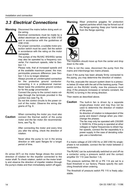
Warning<br />
Wear protective goggles for protection<br />
against particles which may be forced out of<br />
the flange opening. Keep your hands away<br />
from the flange opening.<br />
The impellers should move up from the center and drop<br />
down to the side.<br />
If this is not the case, disconnect the pump from the<br />
mains and interchange two mains phases.<br />
Even if the pump has been already firmly connected to<br />
the piping, you may determine the direction of rotation.<br />
For this, evacuate the vacuum system down to a pressure<br />
below 20 mbar with the aid of the backing pump. Then<br />
switch on the RUVAC briefly; now the pressure must<br />
drop. If the pressure increases or remains constant, the<br />
RUVAC is turning in the wrong direction.<br />
Then rewire as described above.<br />
Caution<br />
The built-in fan is driven by a separate<br />
single-phase motor and may thus not be<br />
used to determine the direction of rotation<br />
of the pump.<br />
Its direction of rotation is independent of the<br />
pump and doesn’t change when you interchange<br />
the phases.<br />
The fan may only be operated with 230/265<br />
V, 50/60 Hz. If the pump is operated at other<br />
voltages or higher frequencies to obtain higher<br />
speeds, connect the fan separately to a<br />
power supply. In the case of deviating voltages<br />
use a transformer.<br />
If a mains voltage of 230 V/50 Hz or 265 V/60 Hz singlephase<br />
is not available, connect the fan motor between 2<br />
conductors.<br />
The RUVAC can be automatically switched on and off via<br />
a contactor using a pressure switch and the contact<br />
amplifier SV 110 (see Section 1.4).<br />
The pressure switches SM 42 or PS 114 are set to a<br />
fixed threshold in our factory. Please specify the switching<br />
threshold when ordering.<br />
The threshold of pressure switch PS 115 is freely adjustable.<br />
14 GA 03.108/7.02 - 11/96


