The Development of Heat Pump Water Heaters Using CO2 Refrigerant
The Development of Heat Pump Water Heaters Using CO2 Refrigerant
The Development of Heat Pump Water Heaters Using CO2 Refrigerant

You also want an ePaper? Increase the reach of your titles
YUMPU automatically turns print PDFs into web optimized ePapers that Google loves.
- 1 -<br />
<br />
<strong>The</strong> <strong>Development</strong> <strong>of</strong> <strong>Heat</strong> <strong>Pump</strong> <strong>Water</strong> <strong>Heat</strong>ers <strong>Using</strong> CO 2 <strong>Refrigerant</strong><br />
<br />
<br />
<br />
<br />
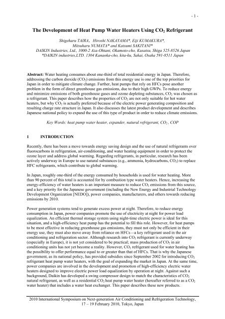
Abstract: <strong>Water</strong> heating consumes about one-third <strong>of</strong> total residential energy in Japan. <strong>The</strong>refore,<br />
addressing the carbon dioxide (CO 2 ) emissions from this energy use is one <strong>of</strong> the top priorities for<br />
Japan in order to mitigate climate change. Further, heat pumps that rely on HFCs pose another<br />
problem in the form <strong>of</strong> direct greenhouse gas emissions, due to their high GWPs. To reduce energy<br />
and minimize emissions <strong>of</strong> both greenhouse gases and ozone depleting substances, CO 2 was chosen as<br />
a refrigerant. This paper describes how the properties <strong>of</strong> CO 2 are not only suitable for hot water<br />
heaters, but why CO 2 is actually preferred because <strong>of</strong> the electric power generating composition and<br />
resulting charge rate structure in Japan. It also discusses the latest product development and describes<br />
Japanese national policy to expand the use <strong>of</strong> this type <strong>of</strong> product in order to reduce climate emissions.<br />
<br />
1 INTRODUCTION<br />
Recently, there has been a move towards energy saving design and the use <strong>of</strong> natural refrigerants over<br />
fluorocarbons in refrigeration, air-conditioning, and water heating equipment in order to protect the<br />
ozone layer and address global warming. Regarding refrigerants, in particular, research has been<br />
actively underway in Europe to use natural substances (e.g., ammonia, hydrocarbons, CO 2 ) to replace<br />
HFC refrigerants, which contribute to global warming.<br />
In Japan, roughly one-third <strong>of</strong> the energy consumed by households is used for water heating. More<br />
than 90 percent <strong>of</strong> this total is accounted for by combustion type water heaters. Hence, increasing the<br />
energy-efficiency <strong>of</strong> water heaters is an important measure to reduce CO 2 emissions from this source,<br />
and a key priority for the Japanese government (including the New Energy and Industrial Technology<br />
<strong>Development</strong> Organization [NEDO]), power companies, manufacturers, and others towards reducing<br />
emissions by 2010.<br />
Power generation systems tend to generate excess power at night. <strong>The</strong>refore, to reduce energy<br />
consumption in Japan, power companies promote the use <strong>of</strong> electricity at night for power load<br />
equalization. An efficient thermal storage system using night-time electric power is ideal for this<br />
situation, and a high-efficiency heat pump has the potential to fill this role. However, for heat pumps<br />
to be most effective in reducing greenhouse gas emissions, they must not only be efficient in their<br />
energy use, they must also move away from reliance on HFCs—a key refrigerant used in the air<br />
conditioning and refrigeration sector. Although research into CO 2 refrigerant is currently underway<br />
(especially in Europe), it is not yet considered to be practical; mass production <strong>of</strong> CO 2 in air<br />
conditioning units has not yet become a reality. However, CO 2 refrigerant used for water heating has<br />
the possibility to <strong>of</strong>fer performance equal to or greater than that <strong>of</strong> HFCs. That is why the Japanese<br />
government, as its national policy, has provided subsidies since September 2002 for introducing CO 2<br />
refrigerant heat pump water heaters, with the goal <strong>of</strong> expanding the market in Japan. At the same time,<br />
power companies are involved in the development and promotion <strong>of</strong> high-efficiency electric water<br />
heaters designed to improve electric power load equalization by operation at night. Against such a<br />
background, Daikin has developed a swing compressor design to match the characteristics <strong>of</strong> CO 2<br />
natural refrigerant, as well as a residential CO 2 heat pump water heater (hereafter referred to as a CO 2<br />
water heater) that includes a water heat exchanger. This paper describes these new products.<br />
2010 International Symposium on Next-generation Air Conditioning and Refrigeration Technology,<br />
17 – 19 February 2010, Tokyo, Japan
- 2 -<br />
2 REFRIGERANT CHARACTERISTICS<br />
Studies were conducted to compare the performance <strong>of</strong> non-fluorocarbon refrigerants (e.g., CO 2 ) to<br />
HFC refrigerants, namely R-410A (HFC32/125=50/50wt%) and R-407C<br />
(HFC32/125/134a=23/25/52wt%) for use in residential heat pump water heaters. Table 1 presents the<br />
characteristics <strong>of</strong> the HFCs and R-744 (CO 2 ). As shown, R-410A and R-407C have somewhat higher<br />
COP but far higher GWP than R-744. As Table 1 shows, suitable refrigerants must be selected for<br />
different applications, i.e., HFCs are suitable for residential air conditioners and packaged air<br />
conditioners, while CO 2 is suitable for water heaters.<br />
<strong>The</strong> CO 2 water heater systems consist <strong>of</strong> three-unit components: the heat pump unit, the hot water<br />
storage unit and the remote controller. <strong>The</strong> heat pump unit draws heat from the atmosphere,<br />
compresses the heated refrigerant to heat it further, and transfers the heat to water to make it hot. <strong>The</strong><br />
storage unit stores the hot water. <strong>The</strong> remote controllers installed in the kitchen and the bathroom<br />
enable the user to draw hot water when needed. <strong>The</strong> advantages <strong>of</strong> the CO 2 water heater are that: the<br />
ODP <strong>of</strong> the refrigerant is 0 and GWP <strong>of</strong> that is 1; it can heat water up to 90 without a heater; the<br />
heat pump method <strong>of</strong>fers energy saving and safety; and it is <strong>of</strong> the night-time thermal storage type,<br />
contributing to electric power load equalization in Japan [1]. In addition, a CO 2 heat pump water<br />
heater can boil additional water more efficiently than traditional electric water heaters <strong>of</strong> night-time<br />
thermal storage type. Based on design requirements, the size <strong>of</strong> the tank can be reduced, so the 370 L<br />
tank has grown to be more popular than the 460 L tanks <strong>of</strong> most traditional electric water heaters.<br />
Hot water is typically used differently by Japanese households compared to other countries. <strong>The</strong><br />
Japanese are the fondest <strong>of</strong> bathing in the world. Given this, they need a large amount <strong>of</strong> hot water at<br />
one time to fill a bath almost everyday. <strong>The</strong> quantity used for this purpose is double that in Western<br />
countries. On the other hand, the hourly water heating capacity <strong>of</strong> most CO 2 water heaters is lower<br />
than that <strong>of</strong> combustion type water heaters due to cost considerations. Accordingly, it is hard to heat a<br />
large amount <strong>of</strong> water at one time using a CO 2 water heater. This means that, if a large amount <strong>of</strong> hot<br />
water is required at one time, it is more cost-effective to heat water in advance. Considering these<br />
conditions, in order to achieve a system favorable to both consumers and electric power companies,<br />
and to compensate for the drawbacks <strong>of</strong> a heat pump, the heat pump unit is run at night, when electric<br />
power is cheaper to pool hot water in the tank and provide it in the daytime [2]. Figure 1 shows the<br />
electricity rates. <strong>The</strong> CO 2 water heater has been designed to maximize the benefit <strong>of</strong> this kind <strong>of</strong> rate<br />
system, which promotes the use <strong>of</strong> electricity at night for power load equalization.<br />
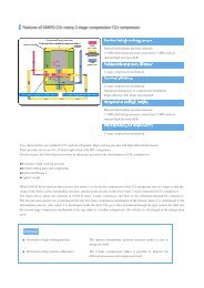
3. TECHNOLOGICAL DEVELOPMENT OF MAJOR COMPONENTS<br />
New compressors and water heat exchangers were the major components developed for heat pump<br />
units <strong>of</strong> CO 2 water heaters. <strong>The</strong>se components are outlined below.<br />
3.1 Swing Compressor<br />
In a CO 2 water heater that is heating water to a high temperature, the pressure on the high pressure<br />
side <strong>of</strong> the refrigeration cycle is typically more than three times that <strong>of</strong> R-410A used in an air<br />
conditioner. <strong>The</strong>refore, when a conventional rotary compressor is used, the reduction in compressor<br />
efficiency caused by internal leaking and the reliability <strong>of</strong> the sliding area on high differential pressure<br />
become concerns. Figure 2 shows the structure <strong>of</strong> a conventional rotary compressor and our developed<br />
swing compressor. With a rotary compressor, imposing a vane on the roller by pressure difference<br />
(between high pressure and the pressure in the compressor chamber) results in areas <strong>of</strong> high and low<br />
pressure, as shown in Figure 2. Because the differential pressure is several times larger in a CO 2 water<br />
heater, wear or burning at the tip <strong>of</strong> the vane causes problems; due to the increase in differential<br />
pressure and the speed <strong>of</strong> sound, internal gas leakage across the vane from the high to low pressure<br />
areas increases. To address this, the Daikin swing compressor combines a vane and roller, as shown in<br />
Figure 2. With the swing compressor, there is no sliding between the vane and roller, so they do not<br />
2010 International Symposium on Next-generation Air Conditioning and Refrigeration Technology,<br />
17 – 19 February 2010, Tokyo, Japan
- 3 -<br />
wear, thereby eliminating gas leakage through the gap. Due to these characteristics, a swing<br />
compressor can perform superbly with CO 2 .<br />
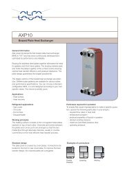
3.2 <strong>Water</strong> <strong>Heat</strong> Exchanger<br />
Generally, a double tube construction is used in water heat exchangers. When this is applied to heat<br />
pump water heaters, a leakage detection ditch is added to prevent mixture <strong>of</strong> refrigerants or oil and<br />
water in the event <strong>of</strong> refrigerant leakage (see double tube shown in Table 2). However, this type <strong>of</strong><br />
double tube has the drawbacks <strong>of</strong> being heavy, expensive, and difficult to reduce in size because the<br />
bending R cannot be reduced. To address this, Daikin developed a new heat exchanger with a capillary<br />
tube acting as a flow channel for CO 2 (see smooth tube shown in the table 2), wound around the core<br />
pipe as water flow and both brazed. <strong>The</strong> shape <strong>of</strong> the water heat exchanger is presented in Figure 3.As<br />
shown, the core pipe is wound on a plane surface, and the wound pipe is arranged to produce a double<br />
layer. <strong>The</strong>refore, the weight and volume <strong>of</strong> the water heat exchanger is about 10 to 30% less than those<br />
<strong>of</strong> a double-tube exchanger. For further energy conservation, a water heat exchanger using an<br />
innovative dimple water tube was developed. As Figure 3 shows, water in the dimpled tube is stirred,<br />
which results in efficient mixing <strong>of</strong> high temperature and low temperature water compared with<br />
conventional heat exchangers to heat water, in which the water flow is straight.<br />
<strong>The</strong> improvement in performance was proven by the image <strong>of</strong> the dimple tube. Figure 4-a) shows an<br />
image <strong>of</strong> the dimple tube. <strong>The</strong> image <strong>of</strong> the protrusion captured from the side <strong>of</strong> the acrylic tube show<br />
the detailed flow around the protrusion. Figure 4-b) shows the downstream whirlpool structure around<br />
the protrusion. <strong>The</strong> flow near the wall continuously forms a small vertical vortex after passing the<br />
protrusion; the vortex has with its central axis along the tube axis, and is about the size <strong>of</strong> the radius <strong>of</strong><br />
the protrusion. Along with this vortex, the flow <strong>of</strong> the main flow side forms a similar vortex as if it is<br />
induced, and both are then mixed as shown in Figure 4-a). As shown by the dashed arrow in Figure 4-<br />
b), a small vertical vortex is formed after the protrusion, which reaches to the tube center on both sides.<br />
<strong>The</strong> improvement in performance was proven by the time-series images <strong>of</strong> the dimple tube. By using<br />
the dimple tube, the heat transfer performance is doubled compared to a smooth tube. <strong>The</strong> accelerated<br />
heat transmission can be seen especially in the low Reynolds number field as shown in Figure 5 [3].<br />
3.3 Steps For <strong>The</strong> Next Generation CO 2 <strong>Water</strong> <strong>Heat</strong>er<br />
A number <strong>of</strong> technological challenges still need to be resolved for water heaters. Two characteristics<br />
in particular—the use <strong>of</strong> ambient air as a heat source, and the storage <strong>of</strong> hot water—are problematic<br />
when larger capacity is required. In Japan’s high density urban areas, space is at a premium. <strong>The</strong><br />
development <strong>of</strong> compact products to fit tight space will be critical for future expansion <strong>of</strong> the CO 2<br />
water heater market. In addition, in order to improve performance <strong>of</strong> CO 2 water heaters, Daikin is<br />
developing an expander to recover energy in the process <strong>of</strong> expansion <strong>of</strong> refrigerant, which is currently<br />
believed to be the most effective way to improve the efficiency <strong>of</strong> the CO 2 cycle [4]. Figure 6 shows<br />
that the expander recovers the energy <strong>of</strong> expansion, which was historically used only for expanding<br />
using the expansion valve. Typically, the expansion <strong>of</strong> isoenthalpy is driven by using an expansion<br />
valve wherein refrigerant cooled by a gas air conditioner expands from the high to low pressure.<br />
However, using an expander can lead to recovery <strong>of</strong> power produced in the process <strong>of</strong> expansion.<br />
When the recovered power is utilized as compression energy, the power consumption <strong>of</strong> the<br />
refrigerant cycle is reduced. Figure 7-a) shows an outline <strong>of</strong> Expander-Compressor Unit. <strong>The</strong> figure<br />
also shows that recovery <strong>of</strong> energy loss due to restriction during decompression process is improved.<br />
Figure 7-b) shows the schematic drawing <strong>of</strong> the hermetically sealed expander-compressor unit. <strong>The</strong><br />
expander built in the expander-compressor is the swing type, like the compression system mentioned<br />
earlier. Daikin developed this prototype for a CO 2 water heater where the expander is connected with<br />
the compressor in one line and the compressor and the motor are located below and the expander is<br />
located above in a closed container, and tested it. As shown in the Figure 7-b), low-pressure<br />
refrigerant sucked into the suction side <strong>of</strong> the compressor is compressed by the compressor system,<br />
goes through the motor and is discharged from the compressor’s discharge side. High-pressure<br />
refrigerant sucked into the suction side <strong>of</strong> the expander is expanded by the expander system and is<br />
2010 International Symposium on Next-generation Air Conditioning and Refrigeration Technology,<br />
17 – 19 February 2010, Tokyo, Japan
- 4 -<br />
discharged from the discharge side <strong>of</strong> the expander. In the expander system, the refrigerant’s<br />
expansion energy generated when it expands is recovered and converted into rotation torque to use it<br />
as part <strong>of</strong> the energy for the compressor.<br />
Table 3 shows specifications <strong>of</strong> a CO 2 water heater system using an expander-compressor. From Table<br />
3, the heating capacity <strong>of</strong> the heat pump is set at 10 kW. <strong>The</strong> system’s performance was evaluated by<br />
relative COP under conditions shown in Figure 8 with equal capacity with a conventional compressorbased<br />
system. Figure 8 shows the results <strong>of</strong> a performance test <strong>of</strong> a CO 2 water heater system using an<br />
expander-compressor. Figure 8 also shows relative evaluation <strong>of</strong> performance <strong>of</strong> an expander and a<br />
compressor, tested separately with and without an expander. Figure 8 shows that the performance<br />
(COP) <strong>of</strong> a system with an expander-compressor was 6.4% higher than that <strong>of</strong> a conventional<br />
compressor. <strong>The</strong> result is confirmed in number between square brackets, in which the efficiency<br />
calculated from the separate test results <strong>of</strong> an expander and a compressor is 108% <strong>of</strong> the efficiency <strong>of</strong><br />
the compressor, which agrees with the test result <strong>of</strong> the expander. This is probably caused by a heatloss<br />
caused by systematization <strong>of</strong> the heat pump equipment and a difference <strong>of</strong> optimization between<br />
ideal control and actual control. <strong>The</strong> results showed that energy requirements for the compressor were<br />
reduced. <strong>The</strong> engineering development work for this CO 2 water heater, expected to be complete in<br />
March 2008, has been carried out by Daikin together with NEDO since June 2005. <strong>The</strong> work has<br />
focused on downsizing the water heater for the purpose <strong>of</strong> expanding its use in high density urban<br />
areas, and on improving system efficiency. However, as there are still cost barriers, more advanced<br />
development <strong>of</strong> this system is needed for market-oriented commercialization.<br />
4. CONCLUSION<br />
<strong>The</strong> development <strong>of</strong> heat pump water heaters using CO 2 natural refrigerant can be summarized as<br />
follows:<br />
- <strong>The</strong> heat transfer performance <strong>of</strong> the dimpled tube used in this water heat exchanger is twice<br />
that <strong>of</strong> a smooth tube.<br />
- <strong>The</strong> mechanism <strong>of</strong> the improved performance was confirmed in a visualizing test.<br />
- This water heat exchanger with improved performance is 10-30% lighter and smaller in<br />
volume than the conventional double-tube heat exchanger, allowing a compact, lightweight<br />
design.<br />
- <strong>The</strong> CO 2 expander for residential Eco Cute products recovers the energy loss <strong>of</strong> the<br />
compressor. Single-unit and system performance tests have demonstrated about 6-8%<br />
improvement in efficiency.<br />
- Thanks to development <strong>of</strong> water heat exchangers, expander-compressors, and other key<br />
components and improvement <strong>of</strong> system technologies, heat pumps may contribute<br />
significantly in future to addressing the challenge <strong>of</strong> global warming.<br />
2010 International Symposium on Next-generation Air Conditioning and Refrigeration Technology,<br />
17 – 19 February 2010, Tokyo, Japan
- 5 -<br />
5. TABLES AND GRAPHS<br />
<strong>Refrigerant</strong><br />
Practical examples<br />
<strong>of</strong> commercialization<br />
Table 1. <strong>Refrigerant</strong> characteristics<br />
HFC<br />
Natural refrigerant<br />
R410A R407C R744(CO 2 )<br />
RAC<br />
PAC<br />
Residential <strong>Water</strong> <strong>Heat</strong>er<br />
PAC<br />
Chiller<br />
(Eco Cute) & Commercial<br />
Commercial <strong>Water</strong> Commercial <strong>Water</strong><br />
<strong>Water</strong> <strong>Heat</strong>er<br />
<strong>Heat</strong>er<br />
<strong>Heat</strong>er<br />
ODP 1 0 0 0<br />
GWP 2 1975 1652.5 1<br />
Combustible No No No<br />
Toxic Low Low Low<br />
Pressure (MPa) (low/ high) 2.7/3.0 1.8/2.0 9.5/11<br />
COP(compared to R410A)<br />
100 95/100 60/80<br />
(low/high)<br />
Note: RAC= residential air-conditioning; PAC= packaged air-conditioning.<br />
1 Ozone depletion potential<br />
2 Global warming potentials are based on IPCC 2001.<br />
Daytime<br />
Summer: ¥29.76/kWh<br />
Other seasons: ¥27.06/kWh<br />
Price (\/kWh)<br />
Night time<br />
¥7.22/kWh<br />
Living time<br />
¥20.67/kWh<br />
Living time<br />
¥20.67/kWh<br />
Time (O’clock)<br />
Figure 1. Electricity rates by season and time (KANSAI ELECTRIC POWER CO.)<br />
At the tip <strong>of</strong> vane:<br />
wear, burn gas leak<br />
Combined vane and roller<br />
No wear, improved reliability,<br />
improved performance due to<br />
less leakage<br />
Vane<br />
Swing Bush<br />
Compression<br />
chamber<br />
Roller<br />
Intake<br />
Crankshaft<br />
Piston<br />
Crankshaft<br />
Figure 2. Comparison <strong>of</strong> conventional rotary and swing compressors<br />
2010 International Symposium on Next-generation Air Conditioning and Refrigeration Technology,<br />
17 – 19 February 2010, Tokyo, Japan
- 6 -<br />
Table 2. Comparison <strong>of</strong> water heat exchanger<br />
Former type<br />
New type<br />
Spec Double tube Smooth tubeinitial time Dimple tubelatest<br />
Outline <strong>of</strong><br />
shape<br />
<strong>Water</strong><br />
Leckage<br />
detection<br />
ditch<br />
Dw,i<br />
<strong>Water</strong><br />
p<br />
CO 2<br />
CO 2 refrigerant<br />
piping<br />
<strong>Water</strong> piping<br />
CO 2<br />
Dimple<br />
Capacity ratio 1.00 0.89 0.89<br />
Weight ratio 1.00 0.74 0.64<br />
Performance 1.00 1.00 1.00<br />
CO 2<br />
Pipe wall<br />
CO 2<br />
<strong>Water</strong><br />
Improvement<br />
<strong>Water</strong><br />
<strong>Water</strong> tube<br />
CO 2 refrigerant tube<br />
Dimple<br />
Figure 3. Improvement <strong>of</strong> a heat transfer rate <strong>of</strong> a water heat exchanger<br />
Flow direction<br />
(a)Flow pattern<br />
(b)Vortex structure<br />
Figure 4. Images around the dimple.<br />
2010 International Symposium on Next-generation Air Conditioning and Refrigeration Technology,<br />
17 – 19 February 2010, Tokyo, Japan
- 7 -<br />
3<br />
2<br />
SD tube<br />
Inner grooved tube<br />
Smooth tube<br />
Nu/Nu0<br />
1<br />
0<br />
0 2000 4000 6000 8000<br />
Re<br />
Figure 5. Evaluation <strong>of</strong> the water heat exchanger<br />
high<br />
<strong>Heat</strong>ing Capacity<br />
P<br />
iso-entropic<br />
expansion<br />
Traditional Cycle<br />
Pressure (MPa)<br />
low<br />
low<br />
Energy<br />
Recovered by<br />
Expander<br />
h<br />
Enthalpy (kJ/kg)<br />
Figure 6. Principle <strong>of</strong> expander-compressor<br />
Compressor<br />
Input<br />
high<br />
Gas air conditioner<br />
Expander<br />
Inlet<br />
Expander<br />
Compressor<br />
Expander<br />
Mechanism<br />
Expander<br />
Outlet<br />
Energy<br />
recovery<br />
Power<br />
recovery<br />
M<br />
Evaporator<br />
Compressor<br />
Discharge<br />
DC<br />
Motor<br />
Compressor<br />
Mechanism<br />
Compressor<br />
Suction<br />
a) Outline <strong>of</strong> improvement <strong>of</strong> efficiency b) Schematic drawing<br />
Figure 7. Outline <strong>of</strong> Expander-Compressor Unit<br />
2010 International Symposium on Next-generation Air Conditioning and Refrigeration Technology,<br />
17 – 19 February 2010, Tokyo, Japan
- 8 -<br />
Table 3. Spec <strong>of</strong> prototype expander-compressor<br />
Expander<br />
Shape<br />
Swing type<br />
Capacity <strong>of</strong> cylinder [cc] 0.7<br />
Compressor<br />
Shape<br />
Swing type<br />
Capacity <strong>of</strong> cylinder [cc] 11.1<br />
Concentrated winding<br />
Shape<br />
Motor<br />
DC motor<br />
Dimension × Thickness [mm] 125×90L<br />
COP ratio<br />
110%<br />
105%<br />
100%<br />
6.4%<br />
with expander<br />
[100%]<br />
[108%]<br />
Number in [ ] : a unit performance <strong>of</strong> an<br />
expander-compressor.<br />
Test conditionJRA rated condition<br />
(Between summer and winter period)<br />
Outdoor temperature DB/WB 16/12<br />
Inlet/Outlet water temperature17/65<br />
Without an<br />
expander<br />
With an<br />
expander<br />
Figure 8. Evaluation <strong>of</strong> system performance<br />
6 REFERENCES<br />
[1] Hirosi NAKAYAMA, Mitsuharu UCHIDA, Masahide HIGUCHI, Yutaka SHIBATA, and<br />
Yasuhiko OKA, <strong>The</strong> development <strong>of</strong> heat pump water heater system with a carbon dioxide<br />
hermetic swing rotary compressor, the 9th Power and Energy Technology Symposium (2004)<br />
[2] Hir<strong>of</strong>umi IDA, <strong>The</strong> development trend and future view <strong>of</strong> the CO 2 refrigerant heat pump water<br />
heater, , September 2007, vol. 82, No. 959.<br />
[3] Mitsuharu NUMATA, Shuji FURUI, and Kazushige KASAI., <strong>Heat</strong> transfer enhancement <strong>of</strong> water-<br />
CO 2 heat exchanger for CO 2 heat-pump water heaters, JSRAE (2006).<br />
[4] Katsumi SAKITANI, Michio MORIWAKI, Masakazu OKAMOTO, Eiji KUMAKURA, and<br />
Tetsuya OKAMOTO., <strong>Development</strong> <strong>of</strong> two-phase flow expander for CO 2 air-conditioners, 8th<br />
IEA <strong>Heat</strong> <strong>Pump</strong> Conference 2005.<br />
2010 International Symposium on Next-generation Air Conditioning and Refrigeration Technology,<br />
17 – 19 February 2010, Tokyo, Japan