XCAPI H.323 TechNote
XCAPI H.323 TechNote
XCAPI H.323 TechNote

You also want an ePaper? Increase the reach of your titles
YUMPU automatically turns print PDFs into web optimized ePapers that Google loves.
<strong>TechNote</strong><br />
<strong>XCAPI</strong> <strong>H.323</strong> <strong>TechNote</strong><br />
Configuring the <strong>XCAPI</strong> with the<br />
Avaya Communication Manager<br />
TE-SYSTEMS GmbH<br />
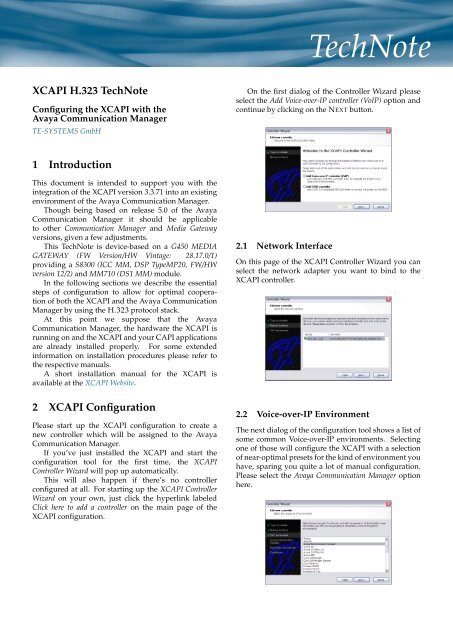
On the first dialog of the Controller Wizard please<br />
select the Add Voice-over-IP controller (VoIP) option and<br />
continue by clicking on the NEXT button.<br />
1 Introduction<br />
This document is intended to support you with the<br />
integration of the <strong>XCAPI</strong> version 3.3.71 into an existing<br />
environment of the Avaya Communication Manager.<br />
Though being based on release 5.0 of the Avaya<br />
Communication Manager it should be applicable<br />
to other Communication Manager and Media Gateway<br />
versions, given a few adjustments.<br />
This <strong>TechNote</strong> is device-based on a G450 MEDIA<br />
GATEWAY (FW Version/HW Vintage: 28.17.0/1)<br />
providing a S8300 (ICC MM, DSP TypeMP20, FW/HW<br />
version 12/2) and MM710 (DS1 MM) module.<br />
In the following sections we describe the essential<br />
steps of configuration to allow for optimal cooperation<br />
of both the <strong>XCAPI</strong> and the Avaya Communication<br />
Manager by using the <strong>H.323</strong> protocol stack.<br />
At this point we suppose that the Avaya<br />
Communication Manager, the hardware the <strong>XCAPI</strong> is<br />
running on and the <strong>XCAPI</strong> and your CAPI applications<br />
are already installed properly. For some extended<br />
information on installation procedures please refer to<br />
the respective manuals.<br />
A short installation manual for the <strong>XCAPI</strong> is<br />
available at the <strong>XCAPI</strong> Website.<br />
2 <strong>XCAPI</strong> Configuration<br />
Please start up the <strong>XCAPI</strong> configuration to create a<br />
new controller which will be assigned to the Avaya<br />
Communication Manager.<br />
If you’ve just installed the <strong>XCAPI</strong> and start the<br />
configuration tool for the first time, the <strong>XCAPI</strong><br />
Controller Wizard will pop up automatically.<br />
This will also happen if there’s no controller<br />
configured at all. For starting up the <strong>XCAPI</strong> Controller<br />
Wizard on your own, just click the hyperlink labeled<br />
Click here to add a controller on the main page of the<br />
<strong>XCAPI</strong> configuration.<br />
2.1 Network Interface<br />
On this page of the <strong>XCAPI</strong> Controller Wizard you can<br />
select the network adapter you want to bind to the<br />
<strong>XCAPI</strong> controller.<br />
2.2 Voice-over-IP Environment<br />
The next dialog of the configuration tool shows a list of<br />
some common Voice-over-IP environments. Selecting<br />
one of those will configure the <strong>XCAPI</strong> with a selection<br />
of near-optimal presets for the kind of environment you<br />
have, sparing you quite a lot of manual configuration.<br />
Please select the Avaya Communication Manager option<br />
here.
2.3 IP Address of the<br />
Avaya Communication Manager<br />
In the dialog Avaya Communication Manager please<br />
provide the IP address of your gateway.<br />
2.5 Confirmation<br />
The final dialog of the Controller Wizard performs<br />
some checks on the configuration parameters you’ve<br />
made. If any errors are detected here, you can go<br />
back to the respective dialogs and correct the necessary<br />
input.<br />
If everything is correct please use the FINISH button<br />
in order to finally create the new controller.<br />
2.4 Description and Channels<br />
That’s about all information that has to be configured<br />
with the <strong>XCAPI</strong>. The next-to-final dialog of the<br />
Controller Wizard allows you to configure a meaningful<br />
description for the controller you’re going to create.<br />
This isn’t really used anywhere, so you can enter a text<br />
of your choice here.<br />
This dialog, however, also allows configuring the<br />
number of channels that the new controller will<br />
provide. The maximum of available channels for VoIP<br />
trunking depends on your purchased <strong>XCAPI</strong> and ACM<br />
license files.<br />
The controller you’ve just created now will appear<br />
on the main page of the <strong>XCAPI</strong> configuration.<br />
As we’re now finished with all <strong>XCAPI</strong>-related<br />
configuration tasks, please save the changes you’ve<br />
made and exit the configuration tool.<br />
Hint: You need to restart the bound CAPI<br />
applications and/or their running services to<br />
take effect on any controller changes.<br />
– 2 –
3 Configuring the<br />
Avaya Communication Manager<br />
In this configuration example we’ll use the AVAYA<br />
SITE ADMINISTRATION - ACM G450 EMULATION: 531<br />
service to access the ACM device.<br />
Depending on your configuration by other means of<br />
accessing it, such as SECURE SHELL connections might<br />
be available. The communication manager offers a<br />
command-line interface (CLI) which we assume some<br />
general familiarity with. If there are doubts, please refer<br />
to the relevant ACM guides.<br />
3.1 IP Node Names<br />
The Node-Names IP dialog is used for administering the<br />
node names and their interworking IP addresses of the<br />
switch and media processors.<br />
The screenshot below shows that the IP node for the<br />
<strong>XCAPI</strong> is assigned to the application server with the IP<br />
address 192.168.1.222.<br />
The Processor Ethernet interface node name (procr)<br />
is properly assigned with IP address 192.168.1.126.<br />
The according IP-Interface and IP-Network-Region<br />
configuration setup won’t be shown detailed here at<br />
all.<br />
– 3 –
3.2 Signaling Groups<br />
The signaling group dialog is used to specify various<br />
signaling parameters coming into operation for the<br />
related trunk group(s), see chapter Trunk Group starting<br />
on page 6.<br />
The screenshots in this chapter show the used ISDN<br />
signaling group parameters, see signaling-group 1, for<br />
the primary rate interface (PRI) and the <strong>H.323</strong> signaling<br />
parameters, see signaling-group 64, used for the <strong>XCAPI</strong><br />
trunk.<br />
The ISDN signaling group, which should be already<br />
properly configured for your environment, is here used<br />
with the following configuration setup:<br />
• As this signaling group is related to the ISDN<br />
primary rate interface (PRI) the Group Type is set<br />
to isdn-pri.<br />
• The Associated Signaling?<br />
default value y.<br />
flag is used with its<br />
• The Primary D-Channel is related to one of the<br />
trunk group member assigned port, for this<br />
example port 001V216.<br />
• The Call Associated and Non Call Associate<br />
Temporary Signaling Connections (NCA TSC),<br />
in meaning of the Max number of NCA/CA<br />
TSC parameter, must be adjusted to your<br />
communication manager environment.<br />
• The Trunk Group for Channel Selection is, however,<br />
set to 1.<br />
• TSC Supplementary Service Protocol is set b for<br />
using the ISO QSIG protocol.<br />
– 4 –
The <strong>H.323</strong> signaling group is used, beside of some<br />
not mentioned parameters with their default values,<br />
with the following configuration setup:<br />
• The Group Type, as this is the desired<br />
communication protocol for ACM and <strong>XCAPI</strong><br />
interworking is set to the h.323 protocol.<br />
• The Max number of CA/NCA TSC values<br />
specifies how many signaling connections for<br />
supplementary services can be established. Even<br />
for large systems a value of 30 should be<br />
sufficient but might be configured upon your<br />
needs.<br />
• The Trunk Group for Channel Selection is set to the<br />
trunk group number 64.<br />
• The TSC Supplementary Service Protocol is set to<br />
option b, which respectively stands for the ISO<br />
QSIG protocol.<br />
• The Near-end Node Name is assigned to procr<br />
listening to the Near-end Listen Port number 6400.<br />
Here we didn’t use the standard port 1720<br />
because there might listen already other nodes or<br />
trunks to.<br />
Please note that you have to assign the correct<br />
port also to the <strong>XCAPI</strong> controller gateway<br />
configuration, as described in the chapter <strong>XCAPI</strong><br />
Gateway Settings on page 22.<br />
• The <strong>XCAPI</strong>s Far-end Node Name is, obviously,<br />
named to <strong>XCAPI</strong>.<br />
The according Far-end Listen Port is used with port<br />
number 1720.<br />
• The Far-end Network Region is assigned to the IP<br />
network region number 1.<br />
• The DTMF over IP signaling method is used with<br />
the default out-of-band method.<br />
• The Direct IP-IP Audio Connections?, valued y, and<br />
the IP Audio Hairpinning?, valued n, are both used<br />
with their default settings.<br />
• The <strong>H.323</strong> Outgoing Direct Media?<br />
used with its default value n.<br />
parameter is<br />
• For the Interworking Message parameter you need<br />
to specify the right selection, here, however, we<br />
used the ALERTing option, as this is used when a<br />
DS1 is connected to the public network and it is<br />
determined that callers hear silence (rather than<br />
ringback or busy tone) when a call incoming over<br />
the DS1 interworks to a non-ISDN trunk.<br />
• The parameter DCP/Analog Bearer Capability is<br />
also used with its default value 3.1kHz.<br />
– 5 –
3.3 Trunk Groups<br />
The Trunk Group dialog is used for trunk-related<br />
parameter configurations and their port assignments.<br />
This chapter describes the most important parameters<br />
for setting up an <strong>XCAPI</strong>-related <strong>H.323</strong> trunk.<br />
The ISDN trunk configuration, which is used for this<br />
<strong>TechNote</strong>s configuration setup, will be also shown but<br />
not described in its details.<br />
3.3.1 <strong>H.323</strong> Trunk Group<br />
The <strong>H.323</strong> trunk group configuration is used, beside of<br />
some not mentioned parameters, with its default values<br />
as described below:<br />
• The <strong>H.323</strong> trunk, which corresponds between the<br />
ACM and the <strong>XCAPI</strong>, is for this example created<br />
on Group Number 64 and used with the unique and<br />
meaningful Group Name called <strong>XCAPI</strong>.<br />
• The isdn Group Type specifies using a digital<br />
trunk, in meaning of voice and data services,<br />
which provides the necessary bandwidth for its<br />
according applications. The Carrier Medium for<br />
this trunk group is set to <strong>H.323</strong>.<br />
• According to your Class of Restrictions (COR) and<br />
Facility Restriction Levels (FRLs) configurations<br />
you need to assign the relevant COR for this<br />
<strong>H.323</strong> trunk. As seen on the screenshot, for this<br />
example the COR number 1 is used.<br />
• The Trunk Access Code (TAC) is set to *64.<br />
• The Direction parameter is set to two-way for<br />
allowing network call redirections.<br />
• The Outgoing Display? parameter is set to option<br />
y, which allows telephones to display the name<br />
and the number of the trunk group.<br />
Here you might select value n for displaying only<br />
the digits the caller dials.<br />
• The Dial Access? parameter is set to y to allow<br />
users route outgoing calls through a trunk group<br />
by dialing its trunk access code.<br />
• The Service Type is used with the tie option.<br />
• The Member Assignment Method parameter is used<br />
with its default value manual.<br />
– 6 –
3.3.2 Trunk Parameters<br />
The Trunk Parameters of the here described <strong>H.323</strong> Trunk<br />
Group is used with the following settings:<br />
• The Supplementary Services parameter needs to<br />
be set to option b in order to support QSIG.<br />
This, of course, only needs to be set when using<br />
supplementary services from within your CAPI<br />
application.<br />
• For this example, the Disconnect Supervision In?<br />
parameter is set to y, thus allows trunk-to-trunk<br />
transfer involving trunks in this group.<br />
This field and the Trunk-to-Trunk Transfer<br />
parameter of the Feature-Related System Parameters<br />
dialog must be set to y.<br />
The Disconnect Supervision Out? parameter is left<br />
by its default value n.<br />
– 7 –
3.3.3 Trunk Features<br />
The Trunk Features of the here described <strong>H.323</strong> Trunk<br />
Group is used with the following settings:<br />
• The NCA-TSC Trunk Member, is set to value 1 and<br />
needs to be adjusted upon your needs.<br />
• The Send Calling Number parameter is set to value<br />
y for interworking with the ISDN Numbering<br />
- Public/Unknown Format or ISDN Numbering -<br />
Private screen settings.<br />
• As the Send Calling Number parameter is enabled,<br />
it’s necessary to specify a Format parameter.<br />
Here the option unk-pvt is used which determines<br />
the Type of Number from the Numbering - Private<br />
Format screen but the Numbering Plan Indicator<br />
(NPI) is unknown.<br />
• As the QSIG Value-Added parameter is enabled,<br />
see next chapter QSIG Trunk Group Options, it’s<br />
necessary to specify a Send Called/Busy/Connected<br />
Number parameter. Here the value y is selected,<br />
which indicates that the ISDN Numbering -<br />
Public/Unknown Format and/or ISDN Numbering<br />
- Private dialog is used. It must be enabled<br />
when the Calling Party Number of an incoming<br />
ISDN call has to be displayed at the transferred-to<br />
station after a QSIG transfer operation.<br />
– 8 –
3.3.4 QSIG Trunk Group Options<br />
Beside of the default values of this configuration screen,<br />
the settings are used as follows:<br />
• The Path Replacement Method is set to always,<br />
for using any QSIG (SBS) trunk group as the<br />
replacement trunk group.<br />
• The SBS parameter (Separation of Bearer and<br />
Signaling) is used with its default value n.<br />
• The QSIG Value-Added?, as mentioned in the<br />
chapter Trunk Features before, is enabled by value<br />
y which provides QSIG-VALU services.<br />
• The QSIG-Value Coverage Encoding parameter is<br />
used with its proprietary default value, which<br />
provides extension information in the normal<br />
manner.<br />
3.3.5 Trunk Group Member Assignments<br />
Within the Trunk Group Member Assignments dialog you<br />
need to setup an amount of members, in meaning of<br />
ports/channels, according to this <strong>H.323</strong> trunk group.<br />
A trunk group offers configuring a number of<br />
so called ports which can be assigned to different<br />
signaling groups. For this example 8 ports were<br />
assigned by entering the value IP as signaling group,<br />
which becomes automatically related to the free port<br />
addresses after saving the Trunk Group configuration.<br />
Each entry is assigned to the according Signaling Group<br />
(Sig Grp) number 64, as described in the chapter<br />
Signaling Group starting on page 4.<br />
– 9 –
3.3.6 ISDN Trunk Group<br />
The ISDN Trunk Group settings for this example are<br />
used as shown on screenshot below.<br />
– 10 –
3.4 Route Patterns<br />
Each route pattern contains one or several trunk groups<br />
that can be used for routing calls. You may have to<br />
insert or delete some digits for routing AAR or ARS calls<br />
over different trunk groups, or need to convert an AAR<br />
number to an international number with the Numbering<br />
Format parameter for your numbering plan.<br />
For this example route-pattern 1 is used with its<br />
default values and was assigned to the properly<br />
operating ISDN trunk group (Grp No) 1.<br />
The Facility Restriction Level (FRL) is set to level<br />
1, which is also used for the forthcoming described<br />
<strong>XCAPI</strong> route pattern.<br />
The CA-TSC Request parameter is used with option<br />
as-needed. This is the Avaya recommended entry for<br />
most situations. The Numbering Format parameter is<br />
set to unk-unk, which specifies the unknown-unknown<br />
format of the routing number used for the trunk group<br />
for this preference.<br />
– 11 –
3.5 Incoming Call Handling<br />
With the Incoming Call Handling Treatment dialog, you<br />
can configure unique call treatments for different<br />
incoming calls on any ISDN trunk group.<br />
This chapter is not essential for setting up<br />
the <strong>XCAPI</strong>-related <strong>H.323</strong> trunking, but shortly<br />
described for giving an overview of this example<br />
used numbering and the call handling. Here, the<br />
inc-call-handling-trmt trunk-group 1<br />
is used with a called length, see parameter Called Len,<br />
of 6 digits. This describes the number of digits received<br />
for an incoming call, which consist of the following<br />
three parts.<br />
The local Called Number 450 specifies the leading<br />
digits received for an incoming call, which becomes<br />
deleted again shortly after its detection by the<br />
parameter Del valued with 3.<br />
The Auto Alternate Routing (AAR) Access Code<br />
number 6, as described in the chapter Feature Access<br />
Codes (FAC) starting on page 12, is assigned to the<br />
Feature Access Code (FAC) call type of the Dial Plan<br />
Analysis, described in Dial Plan Analysis starting on<br />
page 13.<br />
The according Automatic Alternate Routing (AAR)<br />
configuration, described on page 14, with the dial string<br />
number 6 and a minimum and maximum digit length<br />
of 3, shows that the calling range 600 to 699 is routed to<br />
the <strong>XCAPI</strong>-<strong>H.323</strong> Trunk.<br />
3.6 Feature Access Codes (FAC)<br />
The Feature Access Code (FAC) configuration dialog<br />
assigns the dialed codes to the system features, which<br />
in turn needs to be defined through the dial plan, as<br />
described in the chapter<br />
Dial Plan Analysis starting on page 13.<br />
Here, the Auto Alternate Routing (AAR) Access Code<br />
number 6 is used for accessing the <strong>XCAPI</strong> trunk and<br />
the Auto Route Selection (ARS) - Access Code 1 numbered<br />
with value 0 is used for accessing the public network.<br />
– 12 –
3.7 Dial Plan Analysis<br />
The Dial Plan Analysis Table configuration and the Dial<br />
Plan Parameter settings define the system’s dial plan.<br />
The analysis table determines the dialed strings,<br />
their length and the according call type.<br />
For this example the dialed string 0, in meaning of<br />
the access code for the public network, and the dialed<br />
string 6, in meaning of the access code for the <strong>H.323</strong><br />
trunk of the <strong>XCAPI</strong>, are both set to the call type Feature<br />
Access Code (FAC).<br />
The Dialplan Parameters are used with their default<br />
settings as shown on screenshot below.<br />
3.8 Uniform Dial Plan<br />
This Uniform Dial Plan, which has to be enabled in<br />
the System Parameters Customer-Options (Optional<br />
Features), is used as shown on the screenshot below.<br />
If you have any doubts here, please refer to according<br />
chapters of the Feature Description and Implementation for<br />
Avaya Communication Manager and Administrator Guide<br />
for Avaya Communication Manager Documents.<br />
– 13 –
3.9 Automatic Alternate Routing (AAR)<br />
In this example, all dialed matching numbers from 600<br />
to 699 will be routed to the <strong>XCAPI</strong> with their bound<br />
CAPI application. This is realized, as seen on the next<br />
screenshot, by setting up the Dialed String number 6<br />
and using value 3 for the minimum (Min) and maximum<br />
(Max) parameters. The according Route Pattern is set to<br />
number 64 and the Call Type parameter is assigned to<br />
the AAR.<br />
The Digit Conversion Table is generally used for more<br />
efficient routing. This is not relevant for the here<br />
described <strong>H.323</strong> Trunking at all and just shown to see<br />
this configuration setup as a whole. Here, we use the<br />
Matching Pattern 0 which becomes assigned to the ARS.<br />
– 14 –
3.10 Private Numbering<br />
Configuring Private Numbering Plans allows specifying<br />
the digits to be put in the Calling Number information<br />
element (IE), the Connected Number IE, and the QSIG<br />
Party Number for extensions in the Private Numbering<br />
Plan.<br />
Thus enables properly interworking of services such<br />
as path replacement, see chapter Path Replacement on<br />
page 20, and message waiting indications as described<br />
in the chapter Message Waiting indications on<br />
page 20 or transferring redirection numbers, see chapter<br />
Redirection Number on page 20.<br />
3.11 Class of Restrictions (COR)<br />
Class of Restrictions (COR) control call originations and<br />
terminations. This setup needs only one single COR<br />
for covering the calling privileges. Thus, none calling<br />
or called party restrictions are used here, which surely<br />
needs to be adjusted for your setup.<br />
For this configuration setup the COR number 1<br />
is used with Facility Restriction Level (FRL) 1, which<br />
becomes utilized by the AAR and/or ARS features for<br />
call access determination to an outgoing trunk group.<br />
Both, the Calling and Called Party Restrictions aren’t set<br />
and respectively used with option none.<br />
– 15 –
3.12 Class of Services (COS)<br />
The Class of Services dialog is used for administering<br />
access permissions of the station call processing<br />
features. Here, you might have to modify some<br />
parameters for enabling the desired services.<br />
– 16 –
3.13 IP Codec Set<br />
The IP Codec Set configuration determines the codec<br />
types and their related parameters for voice streaming<br />
and facsimile transmissions.<br />
For this setup the IP codec set number 1 is used with<br />
the G.711MU audio codec, no Silence Suppression and a<br />
Packet Size of 20 milliseconds which is equivalent to 2<br />
Frames Per Pkt.<br />
On the second page of the IP Codec Set dialog,<br />
some advanced configuration settings for facsimile and<br />
signaling behaviors can be made.<br />
Please review the chapter Fax Services starting on<br />
page 21, for a more detailed description.<br />
For this example the codec setup, beside of the not<br />
mentioned default settings, is used as follows:<br />
• The FAX mode is set to off with a Redundancy level<br />
of 0 for using the software fax method, see chapter<br />
Software Fax on page 21.<br />
– 17 –
3.14 Feature-Related System Parameters<br />
The Feature-Related System Parameters implements<br />
system parameters associated with various system<br />
features, which are used as described below:<br />
• The PARAMETERS FOR CREATING QSIG<br />
SELECTION NUMBERS is set to Network Level<br />
number 0 and used with no assigned Level 1 or<br />
Level 2 code.<br />
• The parameter Send Non-ISDN Trunk Group Name<br />
as Connected Name? is enabled with option y<br />
which allows sending a name of the non-ISDN<br />
trunk group as the connected name when a call<br />
routes from ISDN to non-ISDN and the call is<br />
answered.<br />
• The Display Connected Name/Number for ISDN<br />
DCS Calls? parameter is enabled with y which<br />
allows displaying the received connected name or<br />
number for ISDN DCS calls.<br />
• The Send ISDN Trunk Group Name on Tandem Calls?<br />
parameter is also used enabled with option y,<br />
which provides consistent display information, in<br />
meaning of the trunk group name, regardless of<br />
trunk type.<br />
• The Send Custom Messages Through QSIG?<br />
parameter is enabled with option y for providing<br />
appropriate display information.<br />
• The QSIG/ETSI TSC Extension is used with a<br />
therefore unassigned value 199. This is a virtual<br />
extension number, for QSIG Call Independent<br />
Signaling Connections supporting both, ETSI and<br />
QSIG temporary signaling connections.<br />
• The MWI - Number of Digits Per Voice Mail<br />
Subscriber parameter is set to 3 for providing an<br />
indication of the number of digits per subscriber.<br />
• The National CPN Prefix parameter is valued to<br />
0 which applies as prefixes to national calling<br />
numbers for display at receiving telephones.<br />
• The International CPN Prefix parameter is set to 00<br />
which applies as prefixes to international calling<br />
numbers for display at receiving telephones.<br />
• The Path Replacement with Measurements?<br />
parameter is set to y for allowing QSIG path<br />
replacement or DCS with Reroute to be attempted<br />
on measured calls.<br />
• The QSIG Path Replacement Extension parameter<br />
is valued to 198 which is used as part of the<br />
complete number sent in the Path Replacement<br />
Propose message.<br />
• The parameter Path Replace While in<br />
Queue/Vectoring? is disabled with option n.<br />
Here you might have to use option y to allow<br />
Path Replacement after queue/vector processing<br />
has started.<br />
– 18 –
3.15 Stations<br />
This chapter just shows the station configuration<br />
dialog, which were used for this setup, of a 9620 client.<br />
– 19 –
4 Supplementary Services<br />
In this chapter we are going to describe some<br />
basic configurations for supplementary services,<br />
such as message waiting indications or path<br />
replacement. Those services are signaled through VoIP<br />
environments, respectively between the <strong>XCAPI</strong> and the<br />
ACM, by the QSIG protocol family.<br />
For full QSIG functionality, you must set the<br />
Supplementary Service Protocol field on both the Trunk<br />
Group and the Signaling Group screen to b (QSIG).<br />
You must set this field to b, because some QSIG<br />
features, such as QSIG Call Completion and QSIG<br />
Message Waiting Indication, use QSIG feature signaling<br />
on both the bearer call and on an NCA TSC to work<br />
properly.<br />
4.1 Message Waiting Indication<br />
If you wish to use the Message Waiting Indication<br />
supplementary service from within your CAPI<br />
application, some further configuration is needed.<br />
If you don’t need to use this feature you can freely skip<br />
this section. For these configuration tasks to succeed<br />
it’s a prerequisite that you have completed the QSIG<br />
configuration tasks from the previous section.<br />
These dialogs allow a great variety of settings. Here<br />
we have only a closer look to the therefore described<br />
MWI supplementary service, see chapter Feature-Related<br />
System Parameters on page 18.<br />
Here, the QSIG TSC Extension parameter valued 199<br />
is used for specifying a phantom endpoint extension<br />
for QSIG call independent signaling connections and<br />
the MWI - Number of Digits Per Voice Mail Subscriber<br />
parameter is set respectively to 3.<br />
4.2 Path Replacement<br />
The Avaya Communication Manager doesn’t really<br />
support the Call Transfer supplementary service. What<br />
it does support, is the QSIG Path Replacement<br />
supplementary service, which pretty much has the<br />
same effect on the outside, but different inner workings.<br />
With the <strong>XCAPI</strong> and the ACM it’s possible to utilize<br />
Path Replacement automatically, whenever your CAPI<br />
application attempts to perform a call transfer.<br />
If you want to enable this feature (on the <strong>XCAPI</strong>side<br />
it’s enabled by default by the Controller Wizard),<br />
please open the same dialog as in the previous section<br />
by invoking the change system-parameters<br />
features command and forwarding to appropriate<br />
configuration screen.<br />
For this example, as already described in the chapter<br />
Feature-Related System Parameters on page 18, the QSIG<br />
Path Replacement Extension parameter valued by 198 that<br />
will be used as a part of the complete number sent in the<br />
Path Replacement Propose message which also needs to<br />
conform to the dial plan.<br />
4.3 Redirection Number<br />
Some CAPI applications need to receive a redirection<br />
number beside the origin calling number, in meaning<br />
of the calling number transmitted by the redirecting<br />
station.<br />
For this you have to select option unk-pvt for the<br />
Format parameter of the Trunk Group Features dialog, as<br />
described in the chapter Trunk Features on page 8.<br />
– 20 –
5 Fax Services<br />
In this chapter, we are going to describe the necessary<br />
configuration for using Fax services. Please ensure that<br />
the codecs with their related parameters are configured<br />
in the right way.<br />
5.1 Software Fax<br />
With the software fax mode, the <strong>XCAPI</strong> simulates<br />
an analogue Fax device by transmitting modulated<br />
Fax-signals modem-like over the established audio<br />
channels. To configure the software fax mode, please<br />
open the <strong>XCAPI</strong> configuration utility and select in<br />
the advanced configuration mode the <strong>H.323</strong> controller<br />
assigned to the gateway.<br />
Open the configuration tab labeled Features.<br />
Enable the SoftFax mode by setting the Always use<br />
software fax over audio channels option and save the<br />
changes to the <strong>XCAPI</strong> controller configuration.<br />
Further you need to ensure that the according IP<br />
codec set, as shown in the chapter IP Codec Set on<br />
page 17, is used with the FAX Mode parameter OFF.<br />
Software FAX transmissions are only supported when<br />
using non-compressing voice codecs.<br />
– 21 –
6 <strong>XCAPI</strong> Controller Settings<br />
In this chapter we are going to review some <strong>XCAPI</strong>related<br />
controller settings which should be set by<br />
default, when using the <strong>XCAPI</strong> controller wizard and<br />
selecting its Avaya Communication Mangager<br />
Voice-over-IP environment.<br />
The <strong>H.323</strong> configuration tab determines the<br />
tunneling of QSIG-related information.<br />
The QSIG tunneling according to <strong>H.323</strong> Annex M<br />
option has to be disabled and the Non standard tunneling<br />
via H.255.0 FACILITY information elements must be<br />
enabled. The Transmitting direction must be set to option<br />
H.255.0 FACILITY.<br />
6.1 Controller Features<br />
The Controller Features are set by default as shown on<br />
the screenshot below.<br />
6.2 QSIG Settings<br />
Creating a <strong>H.323</strong> controller with help of the<br />
<strong>XCAPI</strong> Controller Wizard ensures setting up optimal<br />
configuration flags by default. Next, we review the<br />
most important QSIG settings of the <strong>H.323</strong> <strong>XCAPI</strong><br />
controller. The option Enable QSIG/PSS-1 derived<br />
supplementary services of the QSIG dialog must be set.<br />
6.3 <strong>XCAPI</strong> Gateway Settings<br />
Finally we review the gateway settings of the created<br />
<strong>XCAPI</strong> <strong>H.323</strong> controller. Here we set the port number<br />
to 6400 as this was defined for the Near-end Listen Port<br />
of the Processor Ethernet interface node name (procr), as<br />
described in the chapter Signaling Groups on page 4.<br />
This port is set by default, within the <strong>XCAPI</strong> and the<br />
ACM configuration to 1720 and might differ from the<br />
default value when it is already reserved by another<br />
signaling group.<br />
– 22 –
– 23 –
Copyright c○ by TE-SYSTEMS GmbH, Wolfsburg. All rights<br />
reserved.<br />
This document is property of TE-SYSTEMS GmbH and protected<br />
by international copyright law.<br />
TE-SYSTEMS GmbH does neither assume any liability or legal<br />
responsibility nor any guarantee for this documents contents and its<br />
context. Moreover, merchantability, fitness for a particular purpose<br />
and accuracy and correctness in general cannot be guaranteed.<br />
TE-SYSTEMS GmbH explicitly grants you the right to distribute,<br />
to duplicate and to store this document, as long as its contents are<br />
neither edited, modified nor used commercially in any way. Should<br />
you desire to use this document in any other way, it’s mandatory that<br />
you contact the copyright holder beforehand in written form.<br />
All software and hardware terms mentioned in this manual are<br />
registered trademarks and should be regarded as such.<br />
– 24 –