SPIRAL ANTENNAS FOR BROADBAND APPLICATIONS
SPIRAL ANTENNAS FOR BROADBAND APPLICATIONS
SPIRAL ANTENNAS FOR BROADBAND APPLICATIONS

Create successful ePaper yourself
Turn your PDF publications into a flip-book with our unique Google optimized e-Paper software.
<strong>SPIRAL</strong> <strong>ANTENNAS</strong><br />
<strong>FOR</strong> <strong>BROADBAND</strong><br />
<strong>APPLICATIONS</strong><br />
Enhanced performance is needed from<br />
antennas, radomes and other microwave<br />
components to support everincreasing<br />
functionality for military communications,<br />
electronic warfare (EW), electronic<br />
intelligence (ELINT), signal intelligence<br />
(SIGINT) and electromagnetic interference<br />
(EMI) measurement applications. There is a<br />
continuing demand for antennas with broader<br />
bandwidth and better controlled radiation patterns<br />
while at the same time reducing size and<br />
weight. Nurad Technologies is working to satisfy<br />
these difficult and sometimes conflicting<br />
requirements by developing ultra-broadband<br />
spiral antennas and mating radomes that offer<br />
high performance over various frequency<br />
ranges, sizes and polarizations.<br />
<strong>SPIRAL</strong> <strong>ANTENNAS</strong><br />
The planar spiral antenna is a member of<br />
the class of self-complimentary radiating structures<br />
that provide frequency independent performance<br />
over wide operational bandwidths.<br />
This class includes helix antennas, bowtie dipole<br />
antennas and certain log-periodic antennas.<br />
The spiral is the most widely used of these<br />
antennas because of its compact form factor<br />
and generally superior performance characteristics.<br />
Spiral antennas have nearly constant input<br />
impedance and are capable of VSWR below<br />
2:1 over more than a decade of bandwidth.<br />
They can be easily designed for either lefthand<br />
or right-hand circular polarization and<br />
provide almost perfectly circularly-polarized<br />
radiation over their full coverage area, with an<br />
axial ratio better than 1 dB on axis. In addition,<br />
spiral radiation patterns are nearly constant<br />
with frequency. All this can be achieved in a<br />
cylindrical volume of approximately 1/3 wavelength<br />
diameter by 1/4 wavelength depth.<br />
The most commonly used spiral antenna<br />
types are the two-arm equiangular and the<br />
two-arm Archimedean planar spirals. The<br />
equiangular spiral is a true self-complementary<br />
structure where the spiral radius grows<br />
logarithmically with rotation angle. The<br />
Archimedean spiral has a linear rate of expansion<br />
and is not truly frequency independent,<br />
but its electrical properties are very similar to<br />
NURAD TECHNOLOGIES INC.<br />
Baltimore, MD<br />
Reprinted with permission of MICROWAVE JOURNAL ® from the January 2005 issue.<br />
©<br />
2005 Horizon House Publications, Inc.
PRODUCT FEATURE<br />
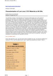
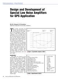
Fig. 1 Cavity-backed spiral<br />
antennas for 100 MHz to 40 GHz. ▼<br />
TABLE I<br />
REPRESENTATIVE <strong>SPIRAL</strong> <strong>ANTENNAS</strong><br />
Frequency Range Size (") Nominal Gain (dBiL)<br />
200 MHz to 1 GHz 21 dia. × 4.3 deep<br />
500 MHz to 2 GHz 10 dia. × 4 deep<br />
600 MHz to 18 GHz 2.4 dia. × 3.5 deep<br />
2 to 18 GHz 2.0 dia. × 1.6 deep<br />
2 to 40 GHz 2.0 dia. × 1.9 deep<br />
6 to 18 GHz 1.0 dia. × 1.6 deep<br />
18 to 40 GHz 0.75 dia. × 1.0 deep<br />
those of the equiangular spiral and it<br />
is easier to manufacture. Figure<br />
1 shows a family of Archimedean<br />
spiral antennas that provide operation<br />
over the frequency range of 100 MHz<br />
to 40 GHz.<br />
These spiral antennas consist of<br />
conducting spiral circuits etched on<br />
dielectric substrates and fed by internal<br />
balun or impedance transformer<br />
assemblies. The spirals are mounted<br />
atop cylindrical aluminum cavities<br />
that are filled with absorbing material,<br />
which work together to generate a<br />
unidirectional radiation pattern from<br />
the otherwise bi-directionally radiating<br />
spiral element. They can be used<br />
in free space, or installed in conducting<br />
ground planes such as the skin of<br />
an aircraft or other vehicle, or installed<br />
in an absorbing or dielectric<br />
structure.<br />
In communication applications<br />
spiral antennas are used as single elements,<br />
as arrays of elements, or as<br />
feeds for reflectors or other high gain<br />
apertures. Single elements are ideal<br />
for low gain systems where wide angular<br />
coverage is needed. Examples<br />
include low data rate satellite communications,<br />
global positioning system<br />
(GPS) and receive-only mobile<br />
systems. Spiral arrays and reflector<br />
systems are typically used in high<br />
gain applications such as high data<br />
rate satellite and terrestrial communication<br />
networks.<br />
In EW applications spiral antennas<br />
are typically used as single elements<br />
or in interferometer small arrays. Single<br />
elements are used in radar warning<br />
systems, SIGINT systems, or low<br />
power jamming systems. Interferometer<br />
arrays employ a set of a few (typically<br />
four) spiral antennas in amplitude<br />
or phasematched<br />
sets and<br />
–8.0 at 200 MHz<br />
+2.0 at 1 GHz<br />
–4.0 at 500 MHz<br />
+1.0 at 2 GHz<br />
–17.0 at 600 MHz<br />
+1.0 at 18 GHz<br />
–7.0 at 2 GHz<br />
+1.0 at 18 GHz<br />
–8.0 at 2 GHz<br />
0 at 40 GHz<br />
–3.0 at 6 GHz<br />
+2.0 at 18 GHz<br />
–2.0 at 18 GHz<br />
0 at 40 GHz<br />
are used to determine<br />
angle-of-arrival<br />
(AOA) of received<br />
signals.<br />
<strong>SPIRAL</strong> ANTENNA<br />
SIZE AND GAIN<br />
Although spiral<br />
antennas have nearly<br />
constant input<br />
impedance over<br />
very broad bandwidths,<br />
their useful<br />
bandwidth is usually<br />
limited by radiation<br />
efficiency at low<br />
frequencies. Most<br />
cavity-backed spiral<br />
antennas have constant peak gain of<br />
approximately 0 to +2 dBiL over a<br />
majority of their operational bandwidths.<br />
But at frequencies below<br />
where the spiral antenna size is less<br />
than approximately 1/3 wavelengths<br />
in diameter, gain rapidly decreases at<br />
a rate of –12 dB/octave. Because of<br />
this gain limitation, applications typically<br />
use spirals over bandwidths of a<br />
decade or less. This is illustrated by<br />
the data in Table 1, which lists frequency<br />
range, size and nominal gain<br />
for a number of different available<br />
spiral antennas. The data shows that<br />
each antenna has roughly the same<br />
gain at its highest frequencies, but<br />
that the electrically small spirals have<br />
low gain at their lowest frequencies.<br />
Note that for narrower bandwidth applications<br />
gain can be increased 2 to 3<br />
dB by eliminating absorbing material<br />
in the cavity.<br />
MODEL A4460 <strong>SPIRAL</strong> ANTENNA<br />
The Nurad model A4460 is an example<br />
of a spiral antenna that strikes<br />
an optimal balance between small<br />
size, broad bandwidth and radiation<br />
efficiency. As shown in Figure 2, this<br />
antenna is a compact cylindrical assembly<br />
with an integral balun and a<br />
single coaxial connector. This righthand<br />
circularly-polarized antenna is 2<br />
inches in diameter by 1.9 inches<br />
deep, operates over the 2 to 40 GHz<br />
frequency range with a nominal<br />
VSWR of less than 2, and provides<br />
high radiation efficiency over the upper<br />
end of its 20:1 bandwidth.<br />
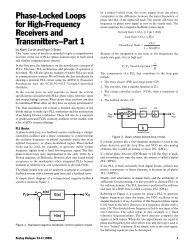
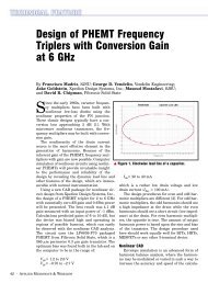
RADIATION PATTERNS<br />
Typical radiation patterns of the<br />
A4460 spiral antenna are shown in<br />
Figure 3. These spinning linear polar<br />
plots at 2 and 40 GHz exhibit the desired<br />
broad beam and symmetric radiation<br />
pattern with low axial ratio on<br />
axis. The antenna provides coverage<br />
0° 0°<br />
−30 30<br />
−30 30<br />
−60<br />
60<br />
−60<br />
60<br />
▲ Fig. 2 The Nurad A4460 Archimedean<br />
spiral antenna.<br />
−90<br />
90<br />
−90<br />
90<br />
−30<br />
−30<br />
−20<br />
−20<br />
−120<br />
−10 120<br />
−120<br />
−10 120<br />
0 dB<br />
0 dB<br />
(a)<br />
−150<br />
150<br />
−150<br />
150<br />
180<br />
(b) 180<br />
▲ Fig. 3 Radiation patterns of the Nurad A4460 antenna at (a) 2 GHz and (b) 40 GHz.
over a fairly wide angular region, with<br />
3 dB beamwidths of 102° at 2 GHz<br />
and 88° at 40 GHz. Peak gain increases<br />
with frequency from –8.0<br />
dBiL at 2 GHz, to 0 dBiL at 40 GHz.<br />
CONCLUSION<br />
A series of high performance spiral<br />
antennas has been developed for EW<br />
and communication applications. The<br />
new model A4460 cavity-backed spiral<br />
antenna operates over the 2 to 40 GHz<br />
frequency range, providing excellent<br />
radiation performance over the entire<br />
20:1 bandwidth. It is suitable for use in<br />
the extreme environment of high dynamic<br />
airborne flight, for which a protective<br />
radome can be included for a<br />
PRODUCT FEATURE<br />
complete airborne antenna system. In<br />
addition, it can be used in matched sets<br />
of phase or amplitude tracking units for<br />
angle-of-arrival detection systems.<br />
Nurad Technologies Inc.,<br />
a division of Chelton<br />
Microwave Corp.,<br />
Baltimore, MD (410) 542-1700,<br />
www.cheltonmicrowave.com.