
Create successful ePaper yourself
Turn your PDF publications into a flip-book with our unique Google optimized e-Paper software.
HYDROCAM ®<br />
The ultimate in flexible cam design*<br />
* HYDROCAM is protected by U. S. and international patents.
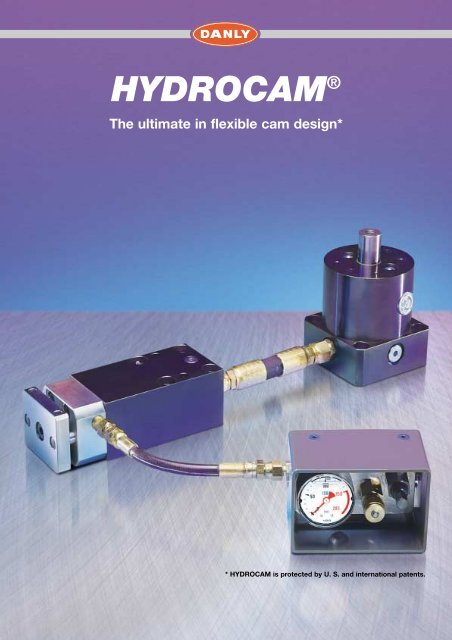
HYDROCAM ® – The standard cam with user flexibility<br />
powerful • compact • reliable • interchangeable<br />
HYDROCAM ® transfers the vertical press stroke<br />
into a precise cam action patenred hydraulic<br />
technology. Standard stocks units combine into<br />
systems. Customers can easily mount their own<br />
tooling to the machinable front plate creating a<br />
customized application.<br />
Here is how HYDROCAM ® operates:<br />
The press ram lowers, activating the piston rod of<br />
the H1 pump. Hydraulic pressure or force is<br />
transfered high pressure hoses to one or multiple<br />
H2 units.<br />
The H2 unit has an adjustable return force using<br />
proven nitrogen gas technology.<br />
• One H1 can serve up to four H2 units.<br />
• Mount the H2 at any angle up to 2 meters aqay<br />
from H1.<br />
• Each H2 can deliver from 2 to 31 tons of force.<br />
• H2 units are aviable with 25, 50, 75 and<br />
100 mm stroke lenghts depending on model<br />
selected.<br />
• Ideal for retrofits and engineering changes.<br />
Index<br />
Introduction HYDROCAM ® 2-3<br />
Selecting charts 4<br />
Calculations 5<br />
H2 Chart 6<br />
H2 Specifications 7<br />
H1 Chart 8<br />
H1 Specifications 9<br />
Installations Guide 10-11<br />
Nitrogen Accessories Control Panel 12<br />
Nitrogen Accessories Fittings 13<br />
Hydraulic Fittings 14<br />
Worksheet for HYDROCAM ® 15<br />
Piercing • Forming • Trimming<br />
2<br />
Changes of construction and errors of printing reserved. All pictures, sketches and details are not binding.
HYDROCAM ®<br />
has been carefully designed for maximum user flexibility.<br />
Our customers can easily mount the<br />
specialized tooling required for their<br />
application to our standard<br />
HYDROCAM ® systems.<br />
Order standard units from stock.<br />
HYDROCAM ® systems shown with control panel<br />
option to monitor and adjust nitrogen pressure in<br />
the H2 piercing/forming unit.<br />
Automotive die … piercing<br />
HYDROCAM ® – Ideal for retrofits and engineering changes<br />
Before<br />
• Costly and complicated<br />
mechanical cams.<br />
• Increased maintenanced costs<br />
due to mechanical wear.<br />
After<br />
• HYDROCAM ® makes retrofits easy.<br />
• Decreased maintenanced costs<br />
and downtime.<br />
Changes of construction and errors of printing reserved. All pictures, sketches and details are not binding.<br />
3
HYDROCAM ®<br />
– Selecting charts<br />
Selecting chart H1<br />
H1<br />
Model<br />
VT Total Volume<br />
V1 Volume/Stroke mm<br />
5<br />
Model<br />
cm 3 2,23<br />
cm 3 50<br />
8<br />
80<br />
3,32<br />
13<br />
130<br />
3,32<br />
20<br />
200<br />
7,85<br />
40<br />
400<br />
13,27<br />
66<br />
660<br />
13,27<br />
Selecting chart H2<br />
H2<br />
Model<br />
Model<br />
2,0<br />
3,2<br />
5,0<br />
7,8<br />
12,5<br />
20,0<br />
31,0<br />
Force<br />
kN<br />
19,63<br />
31,98<br />
49,98<br />
78,01<br />
124,73<br />
199,98<br />
309,97<br />
VC Volume/Stroke mm<br />
cm 3 /mm<br />
0,49<br />
0,8<br />
1,26<br />
1,97<br />
3,11<br />
5,03<br />
7,85<br />
Max. Force<br />
kN<br />
17,87<br />
28,85<br />
45,45<br />
70,94<br />
113,19<br />
188,19<br />
288,17<br />
Return Force at 100 bar<br />
kN<br />
1,76<br />
3,13<br />
4,53<br />
7,07<br />
11,54<br />
11,79<br />
21,8<br />
Note: 1kN = 102 kg<br />
Quick selecting chart<br />
Example:<br />
H2<br />
Model 2,0<br />
Model 3,2<br />
Model 5,0<br />
Model 7,8<br />
Model 12,5<br />
H1<br />
25 mm<br />
50 mm<br />
25 mm<br />
50 mm<br />
75 mm<br />
25 mm<br />
50 mm<br />
75 mm<br />
25 mm<br />
50 mm<br />
75 mm<br />
25 mm<br />
50 mm<br />
75 mm<br />
Model<br />
5<br />
1 (13,4)<br />
2 (18,9)<br />
3 (24,4)<br />
1 (18,9)<br />
1 (16,9)<br />
2 (25,9)<br />
1 (25,9)<br />
1 (22,1)<br />
Model<br />
8<br />
4 (22.7)<br />
2 (22,7)<br />
3 (26,0)<br />
1 (20,0)<br />
1 (26,0)<br />
2 (26,9)<br />
1 (26,9)<br />
1 (22,8)<br />
Model<br />
13<br />
3 (30,1)<br />
4 (37,1)<br />
4 (32,0)<br />
2 (32,0)<br />
1 (26,0)<br />
3 (36,4)<br />
1 (26,9)<br />
1 (36,4)<br />
2 (37,6)<br />
1 (37,6)<br />
1 (31,4)<br />
Model<br />
20<br />
3 (32,2)<br />
4 (28,3)<br />
2 (23,2)<br />
3 (30,9)<br />
4 (24,0)<br />
2 (24,0)<br />
1 (20,0)<br />
3 (26,8)<br />
1 (20,5)<br />
1 (26,8)<br />
2 (27,8)<br />
1 (27,8)<br />
Model<br />
40<br />
4 (26,0)<br />
3 (22,2)<br />
4 (26,9)<br />
2 (22,2)<br />
3 (29,3)<br />
4 (22,8)<br />
2 (22,8)<br />
3 (30,2)<br />
2 (30,2)<br />
3 (25,5)<br />
4 (31,4)<br />
2 (31,4)<br />
1 (25,5)<br />
Model<br />
66<br />
4 (36,4)<br />
4 (37,6)<br />
3 (41,4)<br />
4 (52,5)<br />
3 (43,1)<br />
2 (43,1)<br />
Step 1 and 2<br />
Step 3<br />
Step 4<br />
H2<br />
Locate the H2 unit and its stroke.<br />
In this example: model 3.2, stroke<br />
25 mm.<br />
Locate the number of H2 units to the<br />
right of the stroke lenght. The H1 pump´s<br />
piston rod travel is listed next to that<br />
number in parentheses.<br />
Read up to the column heading. This is<br />
the H1 model you need. In his example:<br />
H1, model 5.<br />
H1<br />
Model<br />
5<br />
Step 4<br />
Model 20,0<br />
Model 31,0<br />
100 mm<br />
25 mm<br />
50 mm<br />
75 mm<br />
100 mm<br />
25 mm<br />
50 mm<br />
1 (24,0)<br />
1 (31,4)<br />
2 (26,9)<br />
1 (26,9)<br />
1 (36,4)<br />
1 (22,7)<br />
1 (31,4)<br />
3 (36,4)<br />
4 (45,9)<br />
2 (45,9)<br />
1 (36,4)<br />
1 (45,9)<br />
2 (37,5)<br />
3 (52,3)<br />
1 (37,5)<br />
Step 2<br />
Step 1<br />
Model 2,0<br />
Model 3,2<br />
25 mm<br />
50 mm<br />
25 mm<br />
50 mm<br />
1 (13,4)<br />
2 (18,9)<br />
3 (24,4)<br />
1 (18,9)<br />
1 (16,9)<br />
2 (25,9)<br />
1 (25,9)<br />
Step 3<br />
75 mm<br />
1 (52,3)<br />
75 mm<br />
4<br />
Changes of construction and errors of printing reserved. All pictures, sketches and details are not binding.
HYDROCAM ®<br />
– Calculations<br />
Example:<br />
Piercing of 2 holes on each ends of a formed part.<br />
Hole diameter: 12 mm, Thickness of material 2 mm;<br />
Material strenghtness: aB 370 N/mm 2<br />
The piercing units makes a stroke of 17 mm before they were stopped by<br />
external tool stops.<br />
Piercing unit HYDROCAM H2<br />
A = d • π • s = 12 mm • π • 2 mm = 75,4 mm 2<br />
F = A • aB = 75,4 mm 2 • 370 N/mm 2 = 27898 N = 27,9 kN<br />
Note the needed force F should be maximum of 80 % of the working force F 2 :<br />
F 27,9 kN<br />
F 2min = –––– = ––––––– = 34,87 kN<br />
0,8 0,8<br />
A = work surface<br />
F = force<br />
aB = max. material tensile strenght<br />
F 2min = working force<br />
Need: Piercing unit HYDROCAM 2 – 5 x 25<br />
Pump HYDROCAM H1<br />
Needed volume for each piercing unit V N1<br />
V N1 = VC • Hub = 1,26 cm 3 /mm • 17 mm = 21,42 cm 3<br />
VT = V N1 • 2 = 21,42 cm 3 • 2 = 42,84 cm 3<br />
Note the needed volume should be maximum of 90% of the Total<br />
volume VT:<br />
VT min = –––<br />
V<br />
= –––––––––<br />
42,84 cm 3<br />
= 47,6 cm<br />
0,9 0,9<br />
3<br />
V N1 = working volume of H2<br />
VC = volume/stroke H2 (cm 3 /mm)<br />
Stroke = real stroke H2<br />
VT min = needed volume H1<br />
VT = total volume<br />
Need: Pump HYDROCAM 1 – 5<br />
Max. Volume stroke Ht4<br />
Ht4 = –––<br />
VT<br />
= –––––––––––<br />
42,84 cm 3<br />
= 19,2 mm<br />
V1 2,23 cm 3 /mm<br />
Total stroke H<br />
H = Ht4 + Ht5 = 19,2 mm + 8 mm = 27,2 mm<br />
V1 = volume/mm stroke H1<br />
Ht4 = max. working stroke H1<br />
Ht3 = total Piston stroke H1<br />
Ht5 = approach stroke H1<br />
Optional stroke gauge ring thickness t<br />
t = Ht3 - H = 31 mm - 27,2 mm = 3,8 mm<br />
Changes of construction and errors of printing reserved. All pictures, sketches and details are not binding.<br />
5
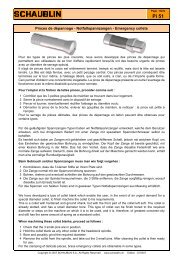
HYDROCAM ® – H2 Piercing unit<br />
Compact power with user<br />
flexibility<br />
The H2 piercing unit can be ordered from<br />
<strong>Danly</strong> with high pressure hose and<br />
connectors you specify.<br />
The H2 has seven standard stock sizes.<br />
The amount of force needed determines<br />
the size. Units deliver from 2 up to 31 tons<br />
of force at any angle selected. Standard<br />
stroke lenghts of 25, 50, 75 and 100 mm,<br />
depending on unit size.<br />
Standard features:<br />
• H2 unit comes with adjustable nitrogen<br />
gas return force.<br />
• Machinable front plate for customers to<br />
mount their tooling by application.<br />
• Compact and interchangeable for today´s<br />
demanding applications.<br />
Popular options:<br />
• Control panel option: DANLY recommends<br />
using this to monitor and adjust<br />
nitrogen return force.<br />
• Direct punch option: Remove front plate<br />
and piston will accept a head type punch.<br />
Punch size and shank limitations are<br />
noted on the H2 dimension chart, see D8<br />
below. A special "lockung nut" must be<br />
ordered.<br />
• Oil return option: Used on special<br />
applications. Must be engineered, please<br />
call <strong>Danly</strong> for support.<br />
Mounting suggestions<br />
• Mount H2 units against keys.<br />
• Provide a mounting platform that will<br />
resist any deflection.<br />
• The standard front plate should be guided<br />
during work stroke. Avoid off-centered<br />
loading.<br />
• Use always an stop block to limit the<br />
stroke of the unit H2.<br />
Example how to order:<br />
Size Stroke Option:<br />
HYDROCAM ® H2 – 5,0 x 25 + Standard<br />
front plate<br />
Note: 1 kN = 102 kg<br />
H2 Chart<br />
Piercing unit<br />
H2<br />
Force<br />
L1 Stroke 25 mm<br />
L1 Stroke 50 mm<br />
L1 Stroke 75 mm<br />
L1 Stroke 100 mm<br />
L2<br />
L3<br />
L4<br />
L5 Stroke 25 mm<br />
L5 Stroke 50 mm<br />
L5 Stroke 75 mm<br />
L5 Stroke 100 mm<br />
L6<br />
L7<br />
B1<br />
B2<br />
B3<br />
Ht1<br />
Ht2<br />
Ht3<br />
Ht4<br />
D1<br />
D2 H7 (x2)<br />
D3 H7 g6 (x2)<br />
D4<br />
Depth<br />
D5<br />
D6 (DIN 75 Km) (x4)<br />
D7 Piston-Ø<br />
D8 Nominal head-Ø<br />
Punch shank-Ø<br />
D9 Thread size of bolt<br />
G<br />
Model<br />
2,0 3,2 5,0 7,8 12,5 20,0 31,0<br />
20 kN 32 kN 50 kN 78 kN 125 kN 200 kN 310 kN<br />
108 128 141 149 172 190 211<br />
133 154 166 174 197 215 236<br />
- 179 191 199 222 240 261<br />
- - - - 247 265 -<br />
8 10 10 12 15 15 20<br />
36 52 55 64 64 77 82<br />
31 42 45 48 55 63 70<br />
101 120 132 138 158 172 190<br />
126 145 157 163 183 197 215<br />
- 170 182 188 208 222 240<br />
- - - - 233 247 265<br />
12 15 20 22 25 30 35<br />
6 8 10 12 16 20 24<br />
60 75 85 100 130 140 180<br />
44 55 65 76 100 110 140<br />
59 74 84 99 129 139 179<br />
50 60 70 80 100 110 150<br />
25 30 35 40 50 55 75<br />
25 30 35 40 50 55 75<br />
49 59 69 79 99 109 149<br />
20 25 32 40 50 70 85<br />
8 10 10 12 12 16 20<br />
12 12 14 16 20 20 24<br />
M12x1,0<br />
17<br />
15 18 20 26 32 32 32<br />
8 10 10 12 16 16 20<br />
25 32 40 50 63 80 100<br />
_<br />
_<br />
M16x1,5<br />
17<br />
13<br />
10<br />
M20x1,5<br />
20<br />
16<br />
13<br />
M30x2,0<br />
21<br />
23<br />
20<br />
M36x2,0<br />
32<br />
28<br />
25<br />
M48x2,0 M56x2,0<br />
38 48<br />
35<br />
32<br />
43<br />
40<br />
M8 M10 M12 M16 M20 M20 M20<br />
G 1/4 G 1/4 G 1/4 G 1/4 G 3/8 G 3/8 G 3/8<br />
6 Changes of construction and errors of printing reserved. All pictures, sketches and details are not binding.
HYDROCAM ®<br />
– H2 Specifications<br />
Direct punch option<br />
L2<br />
L3<br />
D6<br />
N2 inlet port G 1/8<br />
note: H2-2,0 is M6<br />
+ 0.5 mm<br />
L1<br />
L8<br />
L9<br />
B1 + 0.2 mm<br />
B2 + 0.02 mm<br />
G<br />
Vent screw<br />
D4<br />
Option:<br />
Direct round punch<br />
mounting<br />
(Note: limits on punch<br />
shank diameter)<br />
D8<br />
Direct punch<br />
(enlarged view)<br />
Optional: Direct<br />
punch mount<br />
L4 + 0.02 mm<br />
D2<br />
Top view<br />
Option: Standard front mounting plate<br />
D5 ø<br />
D9<br />
GØ – Oil<br />
support port<br />
L1 + 0.5 mm<br />
L6<br />
2x D3 ø<br />
Ht 3<br />
Ht 1 + 0.5 mm<br />
+ 0.02 mm<br />
Ht 2<br />
D1 ø<br />
(B2)<br />
D7 Piston-Ø<br />
B3<br />
Option:<br />
Standard front mounting plate<br />
L7<br />
L5<br />
Side view<br />
Option:<br />
Standard front<br />
mounting plate<br />
Cutaway photo:<br />
Changes of construction and errors of printing reserved. All pictures, sketches and details are not binding.<br />
7
HYDROCAM ®<br />
– H1 Pump<br />
The H1 pump is aviable in six standard<br />
sizes. Each pump has four ports to activate<br />
up to four H2 units. The quality, size and<br />
stroke lenght of the H2 units hosed to each<br />
pump determines the size and oil volume<br />
of the pump needed. Pumps can be up to<br />
six feet away from H2 units.<br />
This allows you to free up critical die space<br />
and balance die loads.<br />
Piston rod travel<br />
Piston rod travel controls oil volume going<br />
to H2 unit(s). Our selection example on<br />
page 5 provides you the formulas for<br />
calculation.<br />
Multiple H2 units activated by a common<br />
pump will effect piston rod travel, find the<br />
quick select chart on page 4.<br />
Optional stroke gauge ring<br />
Used as a visual gauge to assist in set-up.<br />
Ring is located on top pf pump boby and<br />
made to the appropriate height based upon<br />
piston rod travel calculation. This stroke<br />
gauge ring is not a stop block. See quick<br />
select chart on page 4 and calculate<br />
example on page 5 how to calculate.<br />
Mounting Suggestions:<br />
• The piston rod must always face up,<br />
perpendicular to ram/driver.<br />
Always activate piston rod with driver<br />
that is larger in diameter than the piston<br />
rod.<br />
• Driver may need to be custom ground<br />
to exact working height during<br />
HYDROCAM ® system set-up.<br />
• Locate pump higher in elevation than<br />
all H2 units it activates.<br />
• Specify hose lenght and allow for safe<br />
access from pump to H2 unit(s).<br />
Always use stop blocks.<br />
• Die storage blocks are recommended.<br />
Never store pump with piston rod<br />
depressed.<br />
H1 Chart<br />
Pump<br />
VT<br />
Total volume<br />
V1<br />
Volume/Stroke per mm<br />
Ht 1<br />
Die open hight<br />
Ht 2<br />
Height of base<br />
Ht 3<br />
Total stroke<br />
Ht 4<br />
max. volume stroke<br />
Ht 5<br />
Approach stroke<br />
D1<br />
Piston-Ø<br />
D2<br />
Rod-Ø<br />
D3<br />
Body-Ø<br />
D4 min.<br />
(not supported)<br />
D5<br />
Base cross corners<br />
D6<br />
Optional gauge<br />
4-kt 1<br />
4-kt 2<br />
M (x4)<br />
G (x4)<br />
H1<br />
P<br />
Piston area<br />
Example how to order:<br />
HYDROCAM ® H1 – 20<br />
Model<br />
5 8 13 20 40 66<br />
cm 3 50 80 130 200 400 660<br />
cm 3 2,23 3,32 3,32 7,85 13,27 13,27<br />
mm 133 145 195 166 195 275<br />
mm 41 42 57 46 50 70<br />
mm 31 32 47 34 38 58<br />
mm 23 24 39 26 30 50<br />
mm 8 8 8 8 8 8<br />
mm 53,34 65 65 100 130 130<br />
mm 20 25 25 50 60 60<br />
mm 82 100 100 147 182 182<br />
mm 45 55 55 95 120 120<br />
mm 120 141 141 203 246 246<br />
mm 80 98 98 145 180 180<br />
mm 90 105 105 150 185 185<br />
mm 72 84 84 125 150 150<br />
mm Km 8 Km 10 Km 12 Km 12 Km 16 Km 16<br />
BSPP G 1/4 G 1/4 G 1/4 G 3/8 G 3/8 G 3/8<br />
cm 2 22,3 33,2 33,2 78,5 132,7 132,7<br />
8 Changes of construction and errors of printing reserved. All pictures, sketches and details are not binding.
HYDROCAM ®<br />
– H1 Specifications<br />
Driver<br />
(not supplied)<br />
Ø D4<br />
Ht 1 + 0.5 mm<br />
Ht 2 Ht 3<br />
Ht 4 Ht 5<br />
Approach stroke<br />
Volume stroke<br />
G<br />
Piston-Ø<br />
Ø D1<br />
G<br />
Ø D2<br />
Ø D6<br />
Stroke gauge<br />
ring<br />
optional<br />
G<br />
Ø D3<br />
M<br />
G<br />
Ø D5<br />
4-kt 1<br />
4-kt 2<br />
G<br />
G<br />
G<br />
Changes of construction and errors of printing reserved. All pictures, sketches and details are not binding.<br />
9
HYDROCAM ®<br />
Installations guide<br />
Connecting the H1 pump, H2 piercing unit(s)<br />
and Nitrogen return control panel.<br />
1. Minimize the number of fittings in the hose system.<br />
2. Do not use a hose system that involves a fitting – to fitting<br />
– to fitting series of connections.<br />
3. Hose each identical H2 unit to a H1 Pump with ist own<br />
hose. Do not hose in series. Provide simple access for<br />
hose routing. Use only approved hose and fittings.<br />
4. Provide additional hose lenght to ensure appropriate<br />
radius and safe routing. Avoid high spots in the oil hose<br />
route that will trap and create air pockets.<br />
5. Maximum hose lenght is 2 m. Do not substitute the<br />
supplied hydraulic hose with a smaller or lighter duty<br />
hose.<br />
6. Rotating the H1 Pump 45° may simplify hose routing.<br />
7. Avoid turning fittings. If a hose turn requires a turning<br />
fitting, select a 45° fitting as a choice and a 90° fitting<br />
second. See page 12, 13 and 14 for accessories.<br />
Wrong<br />
Right<br />
Requied positions of H1 as compared to H2<br />
See above for proper positioning of the H1 pump.<br />
Sight gauge<br />
Vent Plug<br />
Oil supply port<br />
Vent Plug<br />
Nitrogen inlet port<br />
NOTE: We understand that a few applications will exceed this guide.<br />
Contact your representative for application support.<br />
Model<br />
H dimensions<br />
HYDROCAM H1-5 21 mm<br />
HYDROCAM H1-8 25 mm<br />
HYDROCAM H1-13 25 mm<br />
HYDROCAM H1-20 25 mm<br />
HYDROCAM H1-40 30 mm<br />
HYDROCAM H1-66 30 mm<br />
• Standard HYDROCAM ® systems operate using a<br />
simple hydraulic driven extension with a nitrogen<br />
return and require no special conditions or procedure<br />
to operate them.<br />
• DO NOT SUBSTITUTE ANY COMPONENT IN THIS<br />
SYSTEM! IMPROPER SUBSTITUTIONS MAY RESULT<br />
IN PERFORMANCE PROBLEMS ANS/OR SAFETY<br />
HAZARDS.<br />
• USE ONLY A PREMIUM GRADE HYDRAULIC OIL.<br />
• As with any air, hydraulic or nitrogen cylinder, neither<br />
the H1 Pump nor the H2 unit is designed to withstand<br />
side-thrust forces. Properly guiding the tool and cam<br />
station will limit damage to the cylinder and increase<br />
seal life.<br />
• THE MOST COMMON HYDROCAM ® OPERATING<br />
PROBLEM IS AIR CAUGHT IN THE HOSE<br />
SYSTEM. ENSURE THAT YOU HAVE PROPERLY<br />
LOCATED THE H1 PUMP, AVOIDED HIGH SPOTS IN<br />
THE HOSE SYSTEM AND BLED THE SYSTEM OF AIR.<br />
• Complete engeneering assistance, seminars and<br />
service support are available should a need arise for<br />
any our full line of metal forming products.Contact<br />
your representative for details.<br />
10 Changes of construction and errors of printing reserved. All pictures, sketches and details are not binding.
HYDROCAM ®<br />
Cutaway photos<br />
Follow the instructions for engeneering and production to give a long lifetime of HYDROCAM ® applications:<br />
Installation H2<br />
• The H2 piercing units should alway fixed by a thrust key.<br />
• The pins gives only the position.<br />
• The H2 unit is designed to provide force, not guidance. As with any air, hydraulic or nitrogen cylinder, neither<br />
the H1 Pump nor the H2 unit is designed to withstand side-thrust forces. Properly guiding the tool and cam<br />
station will minimize wear to the cylinders and increase seal life. This is especially true in applications with long<br />
strokes, heavy or large tooling mounted, or in applications that approach the work in a non-perpendicular<br />
presentation.<br />
Note for secure:<br />
Only use fittings and hoses which are proofed to run with 400 bar.<br />
Installation H1<br />
• Use max. hoses with 2 m.<br />
• The Position of the piston should always be right angled and vertical to the driver.<br />
• It don´t work reverse.<br />
• Put the Pump higher than the piercing unit(s).<br />
• Limit the stroke of the tool with a stop block.<br />
• Don´t use more stroke than calculated, compare with the gauge stop ring thickness.<br />
• Fill oil in up to to the middle of the oil sight glass.<br />
• Remove the air in the hoses with initial strokes.<br />
H1<br />
Piston<br />
Rod scraper<br />
Port plug<br />
fill port<br />
Exhaust valve<br />
Oil sight gauge<br />
Body<br />
Oil level<br />
Black ‘O’ Seal<br />
Green ‘O’ Seal<br />
H2<br />
Oil port fitting<br />
Venting<br />
plug<br />
Piston<br />
guide ring<br />
Front U-cup<br />
Seal - nitrogen<br />
Bush U-cup<br />
Seal - nitrogen<br />
Base<br />
Oil port<br />
Rod scraper<br />
seal<br />
Spring<br />
Piston<br />
plug<br />
Piston<br />
Rear U-cup<br />
Seal - oil<br />
H2 Body<br />
(steel)<br />
Front bush<br />
Body seal<br />
Front bush<br />
(bronze)<br />
Changes of construction and errors of printing reserved. All pictures, sketches and details are not binding.<br />
11
Nitrogen accessories control panel<br />
Control panel KA 110-01-250<br />
DANLY suggests to run each H2 with a single Control Panel.<br />
It can use to fill with gas and monitor the pressure.<br />
Each control console has build in a safety plug.<br />
Order-No. KA11001-250<br />
Location of mounting holes and fill connection<br />
15 mm<br />
tief<br />
1. Safety plug 2. Inlet valve 3. Exhaust valve<br />
4. Pressure gauge<br />
Fitting NP1000-3 Order-No. NP1000-3<br />
Order-No. RTUAL-04.0<br />
Fill and control panel<br />
RTUAL-04.0<br />
This is a multi functual unit. Used to<br />
refill and monitor the pressure of gas<br />
filled H2 systems.<br />
Plug Pos. 4<br />
1<br />
2<br />
3<br />
4<br />
5<br />
6<br />
7<br />
8<br />
9<br />
10<br />
11<br />
12<br />
Casing<br />
Pressure<br />
adjusting screw<br />
Body<br />
Threaded plug<br />
Inlet valve<br />
Outlet valve<br />
Retaining ring<br />
Circlips<br />
O-Ring<br />
O-Ring<br />
O-Ring<br />
Gauge<br />
Hoses to connect the<br />
control panels<br />
Important: The lenght should be 5%<br />
longer than the measured distance.<br />
While the systems are filled with high<br />
pressured gas the lenght of the hoses<br />
will be decreased under pressure.<br />
Note: Rebuild the inlet valve of the hoses<br />
units while working with an assembled<br />
control panel.<br />
37° JIC Hose Adaptor for H2-2,0<br />
Order-No. HM6G18<br />
Order-No. RT520410655-(*)<br />
(*) = lenght of the hoses<br />
Part-No.<br />
RT520410655-(*)<br />
Hose<br />
I.D.<br />
Hose<br />
O.D.<br />
Max. oper.<br />
pressure<br />
(bar)<br />
Min. Burst<br />
pressure<br />
(bar)<br />
Min.<br />
Bend radius<br />
Thread<br />
size<br />
A<br />
6-kt<br />
H<br />
6-kt<br />
W<br />
mm 4,8 10,9 345 1380 38 7/16-20 55 16 17 30<br />
B<br />
12 Changes of construction and errors of printing reserved. All pictures, sketches and details are not binding.
Nitrogen accessories fittings<br />
37° Fittings<br />
Straight connector* Swivel nut elbow 135°* 90° Degree elbow*<br />
Order-No. RT4F40MX-S Order-No. RT4V40MX-S Order-No. RT4C40MX-S<br />
* not to connect directly at HYDROCAM<br />
Swivel nut run tee<br />
Swivel nut run tee<br />
90° Degree elbow<br />
Order-No. RT4R6X-S<br />
Order-No. RT4S6X-S<br />
Order-No. RT4C6X-S<br />
Straight connector<br />
Connector for HYDROCAM<br />
Hollow hex plug<br />
Part-No.<br />
T5<br />
6-kt<br />
C5<br />
I1<br />
L1<br />
X Ø<br />
Torque<br />
(Nm)<br />
VSTI-R1/8ED<br />
G-1/8<br />
mm<br />
5<br />
8<br />
12<br />
14<br />
10<br />
VSTI-R1/4ED<br />
G-1/4<br />
mm<br />
6<br />
12<br />
17<br />
19<br />
30<br />
Order-No. NP1100-3<br />
VSTI-R3/8ED<br />
G-3/8<br />
mm<br />
8<br />
12<br />
17<br />
22<br />
35<br />
C5<br />
6-kt<br />
Quick connect fittings<br />
Order-No.:<br />
RT-QDM-6554-A<br />
RT-QDF-0202 (G1/4) Europa<br />
male<br />
female<br />
Connecting hose for nitrogen-gas-bottle<br />
Adaptor<br />
Quick connector<br />
Order-No. NPLS01<br />
Order-No. HDG14JIC12<br />
Order-No. RT-QDF-0202<br />
Changes of construction and errors of printing reserved. All pictures, sketches and details are not binding.<br />
13
Hydraulic fittings<br />
Straight fittings<br />
90° Swivel nut elbow fittings<br />
35<br />
36<br />
11<br />
22.6<br />
19<br />
31.8<br />
9.5<br />
16.7<br />
9.5<br />
16.7<br />
6.3<br />
26 7/16-20<br />
9.5<br />
37 3/4-16<br />
14<br />
22<br />
G-1/4<br />
19<br />
3/4-16<br />
G-3/8<br />
22<br />
3/4-16<br />
G-1/8<br />
G-3/8<br />
Order-No. HDG14<br />
Order-No. HDG38<br />
Order-No. H90G14<br />
Order-No. H90G38<br />
45° Swivel nut elbow<br />
24.9<br />
19<br />
3/4-16<br />
9.5<br />
33<br />
22<br />
G-3/8<br />
Order-No. H45G38<br />
32.5<br />
135° Swivel nut elbow<br />
21.8<br />
10<br />
25<br />
Order-No. HJIC135<br />
10<br />
19<br />
22<br />
3/4-16<br />
3/4-16<br />
90° Swivel nut elbow fitting<br />
1.38<br />
19<br />
24.1<br />
3/4-16<br />
31.8<br />
10<br />
Order-No. HJIC90<br />
22<br />
10<br />
3/4-16<br />
Flexible high pressure hoses and connectors<br />
• Minimize the number of fittings in the hose system.<br />
• Do not use a hose system that involves a fitting – to fitting – to fitting of<br />
connections.<br />
• Hose easch H2 unit to an H1 pump with ist own hose. Do not hose in series.<br />
Provide simple access for hose routing.<br />
• Provide additional hose lenght to ensure appropriate radius and safty routing.<br />
Avoid high spots in the oil hose route that will trap and create pockets.<br />
Hose to connect H1 to H2<br />
Hose Hose Max. oper. Min. Burst Min. Thread<br />
Part-No.<br />
pressure pressure Bend radius<br />
A 6-kt 6-kt B<br />
I.D. O.D.<br />
size<br />
(bar) (bar)<br />
H W<br />
H1H2-10 mm 10 21 445 1780 180 3/4-16 61 18 22 34<br />
H1H2-12 mm 12 25 415 1660 230 3/4-16 66 21 22 36<br />
In case of order the hose lenght is needed.<br />
DANLY Hand pump of 1,8 litre capacity (250 bar maximum output)<br />
Reduce HYDROCAM ® Set-up time by using this hand pump. This oil hand pump can<br />
be used for three different purposes:<br />
1. Directly connected to the H2 unit, it moves the<br />
piston to allow the toolmaker to align punch<br />
and die within the tool.<br />
2. Filling the H1 pump when the system is in the<br />
tool.<br />
3. Filling the oil/nitrogen-accumulator if using oil<br />
return option.<br />
DANLY suggest to use filtered oil SHELL TELLUS 32.<br />
Order-No. HYDPUMPAS<br />
Hand pump with hose<br />
and adapter fittings<br />
1. 2. 3.<br />
Extending H2 piston rod Filling oil drive system Filling oil return system<br />
14 Changes of construction and errors of printing reserved. All pictures, sketches and details are not binding.
For fast quotes … copy this and fax DANLY the details.<br />
Name:<br />
Title:<br />
Company:<br />
Address:<br />
DANLY No:<br />
Date:<br />
City:<br />
State:<br />
Zip:<br />
Telephone:<br />
Fax:<br />
Project, Part No.:<br />
Selection Criteria<br />
Are you piercing holes?<br />
Part material:<br />
B<br />
B<br />
Part thickness:<br />
Tensile strength: N/mm 2<br />
A<br />
A<br />
A<br />
A<br />
Worksheet for DANLY HYDROCAM ® 15<br />
Stripping force:<br />
RAM travel of press:<br />
RAM Strokes/minute:<br />
CAM Stroke length:<br />
Proximity H1 pump to CAM unit<br />
• The H1 pump will be connected by:<br />
Hose length<br />
• Special fittings needed:<br />
hole #1<br />
hole #2<br />
hole #3<br />
hole #4<br />
A<br />
mm<br />
A<br />
mm<br />
What type of stripper?<br />
B<br />
mm<br />
Punch/matrix clearance per side:<br />
A<br />
mm<br />
A<br />
mm<br />
B<br />
mm<br />
(% of part thickness)<br />
• Method used to strip<br />
Are you forming? Describe form:<br />
• Is this used for all holes?<br />
• Comments<br />
What CAM stroke length needed?<br />
H2 #1<br />
H2 #2<br />
H2 #3<br />
mm to be piercing hole #1<br />
mm to be piercing hole #2<br />
mm to be piercing hole #3<br />
Please note special concerns/timing:<br />
H2 #4<br />
mm to be piercing hole #4<br />
Do you want a standard front plate:<br />
or direct punch mount option:<br />
Proximity nitrogen return control<br />
panel to CAM unit<br />
The control panel will be connected by:<br />
• Hose length:<br />
• Special fittings needed:<br />
Sent your worksheet paper for inquiries and orders to:<br />
DANLY Deutschland GmbH · Daimlerstraße 29 · 78083 Dauchingen<br />
Telefon: (0 77 20) 97 23-0 · Telefax: (0 77 20) 97 23-50 · e-mail: info@danly.de · Internet: www.danly.de<br />
Changes of construction and errors of printing reserved. All pictures, sketches and details are not binding.
The Innovator of Our Industry SM<br />
Our factories and offices:<br />
U.S.A. • U.K. • France • Belgium • Germany • Sweden • Netherlands • Singapore<br />
DANLY UK LIMITED<br />
Unit 1, Mucklow Hill 1 Trading Estate,<br />
Mucklow Hill, Halesowen.<br />
West Midlands, B62 8DF<br />
Tel: 0121 585 7171<br />
Fax: 0121 585 7272<br />
DANLY UK LIMITED<br />
2 Aintree Road<br />
Perivale, Middlesex<br />
UB6 7LA<br />
Tel: 0208 998 5381<br />
Fax: 0208 991 2461<br />
E-mail: sales@danlyuk.com