DC Voltage Current Source ADCMT 6166 - Rohde & Schwarz ...
DC Voltage Current Source ADCMT 6166 - Rohde & Schwarz ...
DC Voltage Current Source ADCMT 6166 - Rohde & Schwarz ...

You also want an ePaper? Increase the reach of your titles
YUMPU automatically turns print PDFs into web optimized ePapers that Google loves.
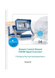
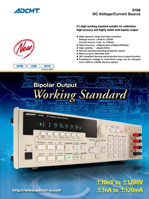
<strong>6166</strong><br />
<strong>DC</strong> <strong>Voltage</strong>/<strong>Current</strong> <strong>Source</strong><br />
6½-digit working standard suitable for calibration<br />
High-accuracy and highly stable with bipolar output<br />
l Wide dynamic range and high resolution<br />
<strong>Voltage</strong> source: ±10nV to ±1200V<br />
<strong>Current</strong> source: ±1nA to ±120mA<br />
l High accuracy: ±35ppm/year (±25ppm/90days)<br />
l High stability: ±5ppm/24hrs<br />
l Smooth polarity switching by bipolar output<br />
l Memory up to 1000 data sets<br />
l JIS-compliant thermal electromotive force output function<br />
l Compliance voltage in 1mA/10mA range can be changed<br />
from ±120V to ±1200V. (factory option)<br />
Factory option<br />
Bipolar Output<br />
Working Standard<br />
http://www.adcmt-e.com
The <strong>6166</strong> is a <strong>DC</strong> voltage/current source that uses a PWM<br />
system in the reference voltage generation block for high accuracy,<br />
high stability and high resolution.<br />
The <strong>DC</strong> voltage can be output over a wide range of ±10nV to<br />
±1199.999V and the <strong>DC</strong> current over a wide range of ±1nA to<br />
±119.9999mA. Especially with its high stability for <strong>DC</strong> voltage<br />
source of 25ppm per 90 days or 35ppm per year (typical<br />
value), the <strong>6166</strong> can be widely used for calibration of highprecision<br />
digital voltmeters or analog indicator instruments<br />
or as a generation source for a variety of tests.<br />
In addition, the <strong>6166</strong> has a built-in function to generate thermal<br />
electromotive force of thermocouples according to the<br />
JIS table, enabling easy calibration of thermometers and<br />
other instrumentation systems.<br />
The GPIB and USB interfaces are installed as standard so<br />
that voltage and current operations are externally programmable.<br />
Also, up to 1000 data including voltage, current, thermocouple,<br />
temperature, voltage limit and current limit can<br />
be stored by hand and read out freely. A simplified auto test<br />
system can be built by nothing but the <strong>6166</strong>.<br />
The BCD parallel interface is available optionally, allowing<br />
more flexible system architect.<br />
JIS-Compliant Thermal Electromotive<br />
Force Output Function<br />
The <strong>6166</strong> has a function to generate thermal electromotive force<br />
of thermocouples according to the JIS table. Selecting the type<br />
of thermocouple and temperature to be generated will output<br />
voltage corresponding to the setting temperature. The type of<br />
thermocouple is selectable from eight types: T, J, E, K, S, R, B<br />
and N. The JIS standard is JISC1602-1995 or JISC1602-1981.<br />
For type N, only JISC1602-1995 is applicable. The reference<br />
junction temperature can be set arbitrarily within a range from<br />
-270°C to 120°C.<br />
This function enables temperature calibration of thermometers<br />
and other instrumentation systems.<br />
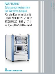
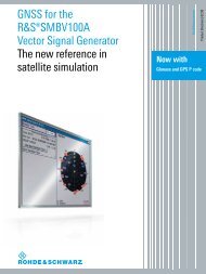
Smooth Polarity Switching by Bipolar Output<br />
As the <strong>6166</strong> employs bipolar output, the source polarity can<br />
alternate between negative and positive without switching the<br />
internal relays. Consequently, even zero-crossing evaluation<br />
is made smoothly in a shorter time. While offering improved<br />
operability, the <strong>6166</strong> can be used free from the concern of the<br />
mechanical parts lifetime.<br />
Unipolar output<br />
<strong>DC</strong> <strong>Voltage</strong>/<strong>Current</strong> Sourcing in 10nV/1nA Steps<br />
The output voltage normally can be set in four ranges of 0<br />
to ±1199.999V in the minimum 1μV steps. When the divider<br />
voltage function is selected, it can be set in three ranges of 0 to<br />
±1199.999mV in the minimum 10nV steps. This is ideal for the<br />
adjustment, test, maintenance and calibration of high-sensitivity<br />
devices and elements.<br />
The output current can be set in three ranges of 0 to<br />
±119.9999mA in 1nA steps.<br />
Both a voltage limit and a current limit can be set for voltage<br />
sourcing (except divider voltage) or current sourcing. They can<br />
protect against damage caused by an operation mistake.<br />
0V<br />
0V<br />
Discontinued around 0V<br />
<strong>6166</strong> bipolar output<br />
No discontinued point<br />
2
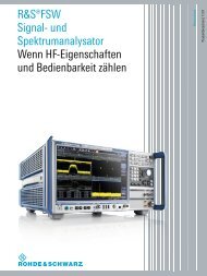
Easy Viewing Display (Dot Matrix VFD Display)<br />
The <strong>6166</strong> adopts an eye-friendly dot matrix vacuum fluorescent<br />
display with increased information capacity.<br />
By using the function, a simplified auto test system can be built<br />
easily and the operating efficiency can be greatly improved.<br />
1-line display: Displays the polarity, setting value and unit for sourcing.<br />
◀Program function capable of various sourcing<br />
using the memory with the capacity of<br />
1,000 data<br />
2-line display: Displays the voltage and current limit values and the<br />
source range in addition to the above. Menu-driven parameter<br />
setting is available, enhancing the usability.<br />
LCD backlighting is used on the primary keys. As the whole<br />
key emits light, the key operability is much improved.<br />
Expanded Specifications for System Use<br />
The <strong>6166</strong> is equipped with the GPIB and USB interfaces. The<br />
BCD parallel interface that is installed on the former model 6161<br />
is also available optionally.<br />
In addition to the TRIGGER IN signal input for starting the output<br />
voltage or current saved in the program memory, the INTER-<br />
LOCK signal input for controlling the output status by a foot<br />
switch, etc. is newly added in consideration of voltage sourcing<br />
up to 1200V, thereby securing easily the safety control.<br />
Greatly Improved Operating Efficiency<br />
by Program Function<br />
The <strong>6166</strong> has a memory with the capacity of 1,000 data sets for<br />
the program function. <strong>Voltage</strong>, current, thermal electromotive<br />
force, temperature, voltage limit and current limit can be stored<br />
in this memory. Any of these data can be output or the data<br />
from the first number through the last number can be scanned.<br />
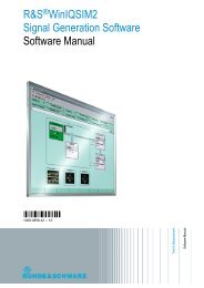
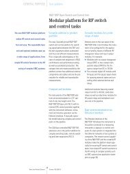
To give flexibility to the output lines incorporated in a system,<br />
the rear output terminals are also mounted.<br />
For external control, the remote commands of the former model<br />
6161 are available by using the compatible mode. The <strong>6166</strong> can<br />
be replaced with a minimum modification of an existing system.<br />
Rear output terminals<br />
USB interface<br />
Trigger signal input<br />
BCD parallel interface<br />
*Factory option<br />
Interlock signal input GPIB interface<br />
<strong>DC</strong> <strong>Voltage</strong> <strong>Current</strong> <strong>Source</strong><br />
3
Specifications<br />
<strong>Voltage</strong>/current source<br />
<strong>Voltage</strong> source range (The 10mV to 1000mV ranges are divided output.):<br />
Range <strong>Source</strong> range Setting resolution<br />
10mV 0 to ±11.99999mV 10nV<br />
100mV 0 to ±119.9999mV 100nV<br />
1000mV 0 to ±1199.999mV 1μV<br />
1V 0 to ±1.199999V 1μV<br />
10V 0 to ±11.99999V 10μV<br />
100V 0 to ±119.9999V 100μV<br />
1000V 0 to ±1199.999V 1mV<br />
<strong>Current</strong> source range:<br />
Range <strong>Source</strong> range Setting resolution<br />
1mA 0 to ±1.199999mA 1nA<br />
10mA 0 to ±11.99999mA 10nA<br />
100mA 0 to ±119.9999mA 100nA<br />
Accuracy (common) : At constant power and load, with a compliance voltage of ±10V or less<br />
Overall accuracy:<br />
Includes calibration accuracy, 1-day stability, the<br />
temperature coefficient, and linearity.<br />
At temperature of 23°C ±5°C and relative humidity of 70%<br />
or less.<br />
Relative accuracy: A value indicating overall accuracy except for the<br />
external standard traceability.<br />
1-day stability:<br />
At temperature of 23°C 1°C<br />
Temperature coefficient 1: At temperature of 23°C 10°C<br />
Temperature coefficient 2: At temperature of 0°C to 13°C, 33°C to 50°C<br />
<strong>Voltage</strong> source accuracy (The 10mV to 1000mV ranges are divided output.):<br />
Overall accuracy<br />
Range 1 year 180 days 90 days 1 day<br />
± (% of setting+V)<br />
10mV 0.0070+2.3μV 0.0065+2.3μV 0.0060+2.3μV 0.0055+0.7μV<br />
100mV 0.0055+2.5μV 0.0050+2.5μV 0.0045+2.5μV 0.0040+0.8μV<br />
1000mV 0.0045+8μV 0.0040+8μV 0.0035+8μV 0.0030+6μV<br />
1V 0.0035+12μV 0.0030+12μV 0.0025+11μV 0.0020+10μV<br />
10V 0.0035+70μV 0.0030+70μV 0.0025+70μV 0.0020+60μV<br />
100V 0.0035+700μV 0.0030+700μV 0.0025+700μV 0.0020+600μV<br />
1000V 0.0040+7mV 0.0035+7mV 0.0030+7mV 0.0025+6mV<br />
Relative accuracy<br />
Range 1 year 180 days 90 days 1 day<br />
± (% of setting+V)<br />
10mV 0.0030+2μV 0.0025+2μV 0.0020+2μV 0.0010+0.5μV<br />
100mV 0.0030+2μV 0.0025+2μV 0.0020+2μV 0.0010+0.5μV<br />
1000mV 0.0030+6μV 0.0025+6μV 0.0020+6μV 0.0010+4μV<br />
1V 0.0025+9μV 0.0020+9μV 0.0015+8μV 0.0005+6μV<br />
10V 0.0025+50μV 0.0020+50μV 0.0015+50μV 0.0005+40μV<br />
100V 0.0025+500μV 0.0020+500μV 0.0015+500μV 0.0005+400μV<br />
1000V 0.0025+5mV 0.0020+5mV 0.0015+5mV 0.0008+4mV<br />
Range<br />
1-day stability (23°C ±1°C) Temperature coefficient 1 Temperature coefficient 2<br />
± (% of setting+V) ± (% of setting+V) / ± (% of setting+V) /<br />
10mV 0.0007+0.3μV 0.0004+0.01μV 0.0005+0.03μV<br />
100mV 0.0007+0.3μV 0.0004+0.07μV 0.0005+0.08μV<br />
1000mV 0.0007+2μV 0.0004+0.6μV 0.0005+0.8μV<br />
1V 0.0005+3μV 0.0002+1μV 0.0004+1.5μV<br />
10V 0.0005+20μV 0.0002+6μV 0.0004+8μV<br />
100V 0.0005+200μV 0.0002+60μV 0.0004+80μV<br />
1000V 0.0005+2mV 0.0003+600μV 0.0005+800μV<br />
<strong>Current</strong> source accuracy:<br />
Overall accuracy<br />
Range 1 year 180 days 90 days 1 day<br />
± (% of setting+A)<br />
1mA 0.0070+9nA 0.0065+9nA 0.0060+9nA 0.0055+9nA<br />
10mA 0.0055+90nA 0.0050+90nA 0.0045+90nA 0.0040+90nA<br />
100mA 0.0055+900nA 0.0050+900nA 0.0045+900nA 0.0040+900nA<br />
Relative accuracy<br />
Range 1 year 180 days 90 days 1 day<br />
± (% of setting+A)<br />
1mA 0.0035+6nA 0.0030+6nA 0.0025+6nA 0.0015+5nA<br />
10mA 0.0030+60nA 0.0025+60nA 0.0020+60nA 0.0010+50nA<br />
100mA 0.0030+600nA 0.0025+600nA 0.0020+600nA 0.0010+500nA<br />
Range<br />
1-day stability (23°C ±1°C) Temperature coefficient 1 Temperature coefficient 2<br />
± (% of setting+A) ± (% of setting+A) / ± (% of setting+A) /<br />
1mA 0.0012+2nA 0.0006+0.7nA 0.0008+0.8nA<br />
10mA 0.0007+20nA 0.0004+7nA 0.0005+8nA<br />
100mA 0.0007+200nA 0.0004+70nA 0.0005+80nA<br />
<strong>Source</strong> linearity:<br />
At temperature of 23°C ±10°C, relative humidity of 70% or less and<br />
constant power and load<br />
For the current range, with a compliance voltage of ±10V or less<br />
(The 10mV to 1000mV ranges are divided output.)<br />
Load regulation/output resistance: In 2-wire connection<br />
(The 10mV to 1000mV ranges are divided output.)<br />
<strong>Voltage</strong> source<br />
<strong>Current</strong> source<br />
Range<br />
Range<br />
10mV<br />
100mV<br />
1000mV<br />
1V<br />
10V<br />
100V<br />
1000V<br />
1mA<br />
10mA<br />
100mA<br />
Load regulation<br />
(Load condition)<br />
Output<br />
resistance<br />
180Ω±0.5%<br />
198Ω±0.5%<br />
200Ω±0.5%<br />
10mV<br />
100mV<br />
—<br />
1000mV<br />
1V ±0.0008 (10Ω or higher) 100mΩ or less<br />
10V ±0.0002 (100Ω or higher) 100mΩ or less<br />
100V ±0.0002 (1kΩ or higher) 100mΩ or less<br />
11GΩ or higher when the compliance voltage exceeds 120V<br />
2Up to ±1200V for the 1mA and 10mA ranges of the OPT<strong>6166</strong>+20<br />
Linearity<br />
±0.03μV<br />
±0.3μV<br />
±4μV<br />
±3μV<br />
±30μV<br />
±400μV<br />
±5mV<br />
±3nA<br />
±30nA<br />
±500nA<br />
Maximum output<br />
Output noise: <strong>Voltage</strong> source: within the range from no-load to maximum load<br />
<strong>Current</strong> source: at load resistance of 1kΩ<br />
(The 10mV to 1000mV ranges are divided output.)<br />
<strong>Voltage</strong><br />
source<br />
<strong>Current</strong><br />
source<br />
3The values in parentheses are for the 1mA and 10mA ranges of the OPT<strong>6166</strong>+20<br />
—<br />
Output current ±120mA<br />
1000V ±0.0002 (100kΩ or higher) 100mΩ or less Output current ±12mA<br />
10mA ±0.0002 (1kΩ or less) 5GΩ or higher *1 Compliance voltage: ±120V *2<br />
1mA ±0.0002 (10kΩ or higher) 5GΩ or higher *1<br />
100mA ±0.0002 (100Ω or less) 1GΩ or higher<br />
Range<br />
Low frequency noise<br />
High frequency noise<br />
0.1Hz to 10Hz (rms) 10Hz to 10kHz (rms) <strong>DC</strong> to 20MHz (p-p)<br />
10mV 0.2μV 20μV 1mV<br />
100mV 0.5μV 20μV 1mV<br />
1000mV 1μV 20μV 1mV<br />
1V 2μV 100μV 3mV<br />
10V 10μV 100μV 3mV<br />
100V 100μV 100μV 3mV<br />
1000V 1mV 1mV 10mV<br />
1mA 5nA 50nA 2μA (10μA) *3<br />
10mA 20nA 200nA 2μA (10μA) *3<br />
100mA 200nA 500nA 10μA<br />
4
Settling time:<br />
Time to settle to the final value ±0.001% when varying from zero to the full scale.<br />
(For the 100mA range, time to settle to the final value ±0.0015%)<br />
(The 10mV to 1000mV ranges are divided output.)<br />
<strong>Voltage</strong> source<br />
<strong>Current</strong> source<br />
4Time to settle to the final value ±0.05% in the 1000V range is within 3s.<br />
For the OPT<strong>6166</strong>+20, time to settle to the final value ±0.005% in the 1mA<br />
and 10mA ranges is within 5s (at load of 1MΩ or less and 100kΩ or less<br />
respectively).<br />
Line regulation±0.0003% of range or less for 100VAC change of 10%<br />
Maximum load capacitance: Maximum value that does not oscillate in<br />
voltage source<br />
Maximum load inductance: Maximum value that does not oscillate in current source<br />
<strong>Current</strong> source: 1mH<br />
CMRR: At unbalanced impedance of 1kΩ between -OUTPUT/-SENSE<br />
terminal and GUARD terminal<br />
<strong>Voltage</strong> output <strong>DC</strong> 140dB or more<br />
50/60Hz ±1% 80dB or more<br />
<strong>Current</strong> output <strong>DC</strong> 140dB or more<br />
50/60Hz ±1% 80dB or more<br />
<strong>Voltage</strong>/current limiter:<br />
Setting range Resolution Setting accuracy<br />
<strong>Voltage</strong> limiter 10V to 1250V 1V ±3% of setting ±5V *5<br />
<strong>Current</strong> limiter 1mA to 125mA 1mA ±3% of setting ±0.8mA<br />
Available except for the divider voltage ranges (10mV, 100mV and 1000mV)<br />
51V is added for current source.<br />
Thermal electromotive force<br />
Thermal electromotive<br />
force source range<br />
Range Settling time Load condition<br />
10mV<br />
100mV<br />
1000mV<br />
1sec or less<br />
1V<br />
—<br />
10V<br />
100V<br />
1000V 10sec or less *4<br />
1mA<br />
100kΩ or less<br />
10mA 1sec or less 10kΩ or less<br />
100mA<br />
1kΩ or less<br />
Range<br />
10mV to 10V<br />
100V<br />
1000V<br />
Maximum load capacitance<br />
1000μF<br />
10μF<br />
1μF<br />
Thermocouple <strong>Source</strong> range Setting resolution<br />
T (CC) -220.0 to +400.0 0.1<br />
J (IC) -210.0 to +1200.0 0.1<br />
E (CRC) -220.0 to +1000.0 0.1<br />
K (CA) -220.0 to +1372.0 0.1<br />
S (PR10) -10.0 to +1768.0 0.1<br />
R (PR13) -10.0 to +1768.0 0.1<br />
B (PR30) +280.0 to +1820.0 0.1<br />
N -220.0 to +1300.0 0.1<br />
Reference junction temperature (cold junction compensation) setting range:<br />
-270°C to +120°C except for the following:<br />
Thermocouple type J: less than -210°C is deemed to be -210°C<br />
Thermocouple type S: less than -50°C is deemed to be -50°C<br />
Thermocouple type R: less than -50°C is deemed to be -50°C<br />
Thermocouple type B: less than 0°C is deemed to be 0°C<br />
Standard setting: JIS C1602-1995 or JIS C1602-1981<br />
For type N, JIS C1602-1995 is applied.<br />
Thermal electromotive force overall accuracy: At temperature of 23°C ±5°C and relative humidity of 70% or less for one year<br />
Thermocouple<br />
T (CC)<br />
J (IC)<br />
E (CRC)<br />
K (CA)<br />
S (PR10)<br />
R (PR13)<br />
B (PR30)<br />
N<br />
<strong>Source</strong> Function<br />
<strong>Source</strong> temperature –<br />
Reference junction temperature<br />
-220.0 to +400.0<br />
-210.0 to +1200.0<br />
-220.0 to +1000.0<br />
-220.0 to +1372.0<br />
-10.0 to +1768.0<br />
-10.0 to +1768.0<br />
+280.0 to +1820.0<br />
-220.0 to +1300.0<br />
Accuracy<br />
Range<br />
-220.0 to -190.1<br />
-190.0 to -70.1<br />
-70.0 to +50.0<br />
+50.1 to +400.0<br />
-210.0 to -170.1<br />
-170.0 to -100.1<br />
-100.0 to +1200.0<br />
-220.0 to -190.1<br />
-190.0 to -80.1<br />
-80.0 to +1000.0<br />
-220.0 to -190.1<br />
-190.0 to -130.1<br />
-130.0 to -80.1<br />
-80.0 to +1240.0<br />
+1240.1 to +1372.0<br />
-10.0 to +50.0<br />
+50.1 to +200.0<br />
+200.1 to +1768.0<br />
-10.0 to +40.0<br />
+40.1 to +160.0<br />
+160.1 to +1768.0<br />
+280.0 to +500.0<br />
+500.1 to +650.0<br />
+650.1 to +950.0<br />
+950.1 to +1550.0<br />
+1550.1 to +1820.0<br />
-220.0 to -210.1<br />
-210.0 to -180.1<br />
-180.0 to -30.1<br />
-30.0 to +1300.0<br />
± (% of setting+)<br />
0.012+0.2<br />
0.009+0.2<br />
0.006+0.1<br />
0.005+0.1<br />
0.006+0.1<br />
0.008+0.1<br />
0.011+0.2<br />
0.012+0.2<br />
0.009+0.1<br />
0.006+0.1<br />
0.012+0.3<br />
0.010+0.2<br />
0.006+0.1<br />
0.006+0.1<br />
0.007+0.1<br />
0.006+0.5<br />
0.006+0.4<br />
0.006+0.3<br />
0.006+0.5<br />
0.006+0.4<br />
0.006+0.3<br />
0.004+0.9<br />
0.004+0.7<br />
0.004+0.5<br />
0.004+0.4<br />
0.004+0.3<br />
0.015+0.4<br />
0.013+0.3<br />
0.009+0.2<br />
0.006+0.1<br />
Program function:<br />
Recall Specifies an arbitrary memory number.<br />
Scan Scans memory numbers one by one by trigger input.<br />
Increments memory numbers at step time intervals.<br />
Scan operation Hold Scans memory numbers one by one by trigger input.<br />
Single Scans from the first number to the last number.<br />
Repeat Scans repeatedly from the first number to the last number.<br />
Maximum memory: 1000 data<br />
Step time: Setting range 1s to 99s<br />
Setting resolution 1s<br />
Limiter:<br />
<strong>Current</strong> limiter<br />
<strong>Voltage</strong> limiter<br />
Output system: Floating, bipolar<br />
Output terminal: Front/rear, biding post<br />
+OUTPUT, +SENSE,<br />
-OUTPUT, -SENSE,<br />
DIVIDED OUTPUT HI,<br />
DIVIDED OUTPUT LO<br />
GUARD, GND<br />
For thermal electromotive force sourcing, the DIVIDED OUTPUT terminals are used.<br />
Maximum input between:<br />
+OUTPUT<br />
and -OUTPUT<br />
+SENSE - SENSE<br />
1200V output max<br />
OUTPUT and SENSE 0.5V peak max<br />
DIVIDED OUTPUT HI and LO 2V peak max<br />
-OUTPUT<br />
-SENSE<br />
DIVIDED OUTPUT LO<br />
and GUARD 50V peak max<br />
GUARD and chassis 50V peak max<br />
Maximum remote sensing voltage between:<br />
[+OUTPUT] and [+SENSE] ±0.1V peak max<br />
[-OUTPUT] and [–SENSE] ±0.1V peak max<br />
*The voltage between [±OUTPUT] and [±SENSE] must be 0.1V<br />
or less including voltage drop due to cable resistance.<br />
(Approx. 10ppm error at 0.1V)<br />
5
GPIB interface Compliant with IEEE-488.2-1987<br />
Interface function SH1, AH1, T6, L3, SR1, RL1, PP0,<br />
<strong>DC</strong>1, DT1, C0, E2<br />
Connector Amphenol 24 pin<br />
USB interface USB 2.0 Full-speed<br />
Connector Type B<br />
BCD parallel interface (factory option):<br />
Remote programming<br />
Output level, polarity, range, Operate,<br />
V/I mode, divider output, voltage limit,<br />
current limit, remote operate input,<br />
operate flag output, limit flag output<br />
Connector Amphenol 50 pin<br />
External control signal TRIGGER IN<br />
INTERLOCK<br />
Connectorn BNC<br />
General Specifications<br />
Operating environment conditions: Ambient temperature 0 to 50<br />
Relative humidity 85% or below, no condensation<br />
Storage environment conditions: Ambient temperature -25ºC to +70ºC,<br />
Relative humidity 85% or below, no condensation<br />
Warming up time : 60 minutes or longer (until the specified accuracy is reached.)<br />
Display:<br />
Dot matrix vacuum fluorescent display<br />
Power supply: AC power 100V/120V/220V/and240V (User selectable)<br />
Option No. Standard OPT. 32 OPT. 42 OPT. 44<br />
Power <strong>Voltage</strong> 100V 120V 220V 240V<br />
Specify the option number when ordering.<br />
When changing the power voltage, use only a power cable<br />
and rated fuse approved for the respective country.<br />
Line frequency: 50Hz/60Hz<br />
Power consumption: 90VA or less<br />
Dimensions: Approx. 424 (width) × 132 (height) × 450 (depth) mm<br />
Mass:<br />
17kg or less<br />
Safety:<br />
Compliant with IEC61010-1 Ed.3<br />
EMI:<br />
Compliant with EN61326 classA<br />
Supplied accessory<br />
Part number<br />
A01402 Power cable (JIS 2m)<br />
Name<br />
Options<br />
Option number<br />
Compliance voltage 1200V (1mA and 10mA ranges)<br />
OPT<strong>6166</strong>+20<br />
(factory option)<br />
BCD parallel interface<br />
OPT<strong>6166</strong>+04<br />
(factory option)<br />
Optional accessories<br />
Part number Name<br />
CC022003 Rack mount set (JIS 3U)<br />
CC024003 Rack mount set (EIA 3U)<br />
CC028003<br />
Front handle set (3U)<br />
A02615<br />
Slide rail set<br />
◦ Please read through the operation manual carefully before using the products.<br />
◦ All specifications are subject to change without notice.<br />
E-mail : kcc@adcmt.com URL : http://www.adcmt-e.com<br />
Head Office<br />
Shoei Bldg, 3-6-12, Kyobashi, Chuou-ku,<br />
Tokyo 104-0031, Japan<br />
Phone: +81-3-6272-4433 Fax: +81-3-6272-4437<br />
Higashimatsuyama Office (R&D Center)<br />
77-1, Miyako, Namegawa-machi, Hiki-gun,<br />
Saitama 355-0812, Japan<br />
Phone: +81-493-56-4433 Fax: +81-493-56-4281<br />
© 2011 A<strong>DC</strong> CORPORATION Printed in Japan <strong>6166</strong>-NP1E Jan. '11 AMS