Controlling External Generators and Power ... - Rohde & Schwarz
Controlling External Generators and Power ... - Rohde & Schwarz
Controlling External Generators and Power ... - Rohde & Schwarz

You also want an ePaper? Increase the reach of your titles
YUMPU automatically turns print PDFs into web optimized ePapers that Google loves.
POWERMEASMINFRQ<br />
= 10e6<br />
; maximum input frequency [Hz]<br />
POWERMEASMAXFRQ<br />
= 20e9<br />
; minimum input power [dBm]<br />
POWERMEASMINPOW = -20<br />
; maximum input power [dBm]<br />
POWERMEASMAXPOW = 10<br />
; IEEE 488 initialization string<br />
; This sequence is sent to the power<br />
; meter to initialize it.<br />
;<br />
POWERMEASINIT = C1,W5,U1,N1,A0,Q1,KF1<br />
; time needed after initialization [sec]<br />
POWERMEASINITDELAY = 1.0<br />
; define zero adjust IEEE 488 comm<strong>and</strong>.<br />
POWERMEASZEROADJUST<br />
= O1<br />
; define power query IEEE 488 comm<strong>and</strong>.<br />
; POWERMEASSETUP (not required)<br />
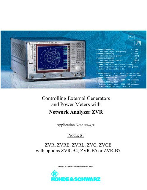
<strong>Controlling</strong> <strong>External</strong> <strong>Generators</strong><br />
<strong>and</strong> <strong>Power</strong> Meters with<br />
Network Analyzer ZVR<br />
Application Note 1EZ46_0E<br />
Products:<br />
ZVR, ZVRE, ZVRL, ZVC, ZVCE<br />
with options ZVR-B4, ZVR-B5 or ZVR-B7<br />
Subject to change - Johannes Ganzert 98-10
Contents<br />
1. Summary................................................................ 2<br />
2. Introduction ............................................................ 2<br />
3. Structure of a Configuration File for a Signal<br />
Generator............................................................... 2<br />
4. Configuration File for Signal Generator SME03..... 3<br />
5. Creating a Configuration File for a <strong>Power</strong> Meter.... 5<br />
6. Configuration File for <strong>Power</strong> Meter NRVS ............. 5<br />
7. References............................................................. 7<br />
8. Ordering Information .............................................. 7<br />
1. Summary<br />
With options ZVR-B4 (mixer measurements), ZVR-B5<br />
(nonlinear measurements) <strong>and</strong> ZVR-B7 (power<br />
calibration) installed, signal generators <strong>and</strong> power<br />
meters can be controlled from ZVR network analyzers<br />
via the IEC/IEEE bus.<br />
Customary signal generators <strong>and</strong> power meters are<br />
supported by the device firmware. This application<br />
note describes how user-specific configuration files<br />
can be generated for <strong>and</strong> adjusted to external<br />
equipment of these two categories.<br />
2. Introduction<br />
The configuration data are located in the directory<br />
C:\USER\DATA, which can be accessed by the user.<br />
Files describing the generator have the extension<br />
.gen, while files for power meters are of the .pwm<br />
type.<br />
If other types of equipment are to be controlled, the<br />
files supplied with the equipment software can be<br />
used as a basis. The originals must not be modified<br />
because they are overwritten during firmware<br />
updates.<br />
In the firmware selection lists, the generator or power<br />
meter is indicated by the associated file name.<br />
Example: The file describing generator SME06 is<br />
named SME06.GEN.<br />
3. Structure of a Configuration File<br />
for a Signal Generator<br />
As a prerequisite of being supported by the firmware,<br />
an external generator must be capable of performing<br />
frequency settings in the st<strong>and</strong>ard unit Hz. Level must<br />
be settable in dBm.<br />
The permissible frequency <strong>and</strong> level ranges are<br />
specified in section [EXT_SRC]:<br />
• GENERATORMINFRQ indicates the lower limit<br />
frequency in Hz;<br />
• GENERATORMAXFRQ indicates the upper limit<br />
frequency in Hz.<br />
In the same way<br />
• GENERATORMINPOW <strong>and</strong><br />
• GENERATORMAXPOW<br />
define the minimum <strong>and</strong> maximum permissible level<br />
in dBm.<br />
The field GENERATORINIT contains the initializing<br />
sequence for the generator. The comm<strong>and</strong>s are<br />
transmitted by the network analyzer as soon as the<br />
basic settings of the generator are initialized.<br />
GENERATORINITDELAY defines the wait time<br />
following initialization.<br />
By means of the comm<strong>and</strong> given in the field<br />
GENERATORINITCW, the generator is switched to<br />
fixed-frequency mode.<br />
The comm<strong>and</strong>s in the fields GENERATORFREQ <strong>and</strong><br />
GENERATORLEVEL are used for setting frequency <strong>and</strong><br />
level. At runtime, the characters %lf are replaced by<br />
the value to be set as a floating-point number. Hz <strong>and</strong><br />
dBm are always used as basic units.<br />
The synchronization mechanism on IEC/IEEE bus is<br />
selected via GENERATORUSEOPC. If the generator<br />
can respond to the comm<strong>and</strong> *OPC according to<br />
IEEE488, enter 1.<br />
If this type of synchronization is not supported, enter<br />
0. In this case, the time the generator has for settling<br />
after each new setting is given in seconds in the next<br />
field GENERATORUSEDELAY.<br />
The key words GENERATORREFEXT <strong>and</strong><br />
GENERATORREFINTERN describe the comm<strong>and</strong>s for<br />
switching to external/internal reference.<br />
1ez46_0e 2 <strong>Rohde</strong> & <strong>Schwarz</strong>
GENERATORIECAVAIL serves for defining whether<br />
the generator supports the hardware h<strong>and</strong>shake<br />
mode. This field contains the value TTL only for a few<br />
generators from <strong>Rohde</strong> & <strong>Schwarz</strong>; normally it is set<br />
to IEC/IEEE (no hardware h<strong>and</strong>shake). If it is set to<br />
IEC/IEEE, the entries<br />
GENERATORLISTMAX,<br />
GENERATORREADYINVALIDTIME,<br />
GENERATORREADYEXACTTIME,<br />
GENERATORFREQLIST,<br />
GENERATORLEVELFORFREQLIST,<br />
GENERATORLEVELLIST,<br />
GENERATORFREQFORLEVELLIST,<br />
GENERATORSELECTLISTBYNAME,<br />
GENERATORDELETELISTBYNAME,<br />
GENERATORSELECTLISTBYNUMBER,<br />
GENERATORDELETELISTBYNUMBER,<br />
GENERATORINITFREQLIST,<br />
GENERATORINITLEVELLIST,<br />
GENERATORINITFREQANDLEVELLIST<br />
<strong>and</strong><br />
GENERATORRESETLIST are irrelevant.<br />
In the field GENERATORERRORMODE, the supported<br />
error-message mode is shown. This value is SCPI for<br />
error messages according to the SCPI st<strong>and</strong>ard,<br />
IEEE if the registers STB <strong>and</strong> ESR according to<br />
IEEE488.2 are used <strong>and</strong> NONE if none of the<br />
mechanisms listed above is supported.<br />
The fields GENERATORRFOFF <strong>and</strong> GENERATORRFON<br />
describe which comm<strong>and</strong>s are to be used for<br />
switching RF power on <strong>and</strong> off.<br />
4. Configuration File for Signal Generator SME03<br />
;*******************************************************************************<br />
;<br />
; COPYRIGHT: (c) 1996 <strong>Rohde</strong> & <strong>Schwarz</strong>, Munich<br />
;<br />
; Generator description file for ZVR family<br />
;<br />
; supports SME03<br />
;<br />
; $Revision: 1.4 $<br />
;<br />
; +------------------------------------------------------------------------+<br />
; | This file must not be modified!. Future changes by R&S without notice. |<br />
; +------------------------------------------------------------------------+<br />
;<br />
; You can use this file as an example to create your own generator<br />
; descriptions. To do this copy the file to a different name! So software<br />
; updates will not modify your files. Your new file will then automatically<br />
; appear in the generator selection list box. We do not guarantee proper<br />
; operation with any generator file not delivered by R&S!<br />
;<br />
;********************************************************************************/<br />
[EXT_SRC]<br />
; minimum output frequency [Hz]<br />
GENERATORMINFRQ<br />
= 5e3<br />
; maximum output frequency [Hz]<br />
GENERATORMAXFRQ = 3.0e9<br />
; minimum output power [dBm]<br />
GENERATORMINPOW = -144<br />
; maximum output power [dBm]<br />
GENERATORMAXPOW = 16<br />
Frequency <strong>and</strong> level range of the<br />
generator<br />
; IEEE 488 initialization string<br />
: This sequence is sent to the generator to initialize it.<br />
; You must turn the generator to external reference, if not, there might<br />
; be problems measuring with small IF b<strong>and</strong>widths.<br />
; You can also set the frequency <strong>and</strong> power to initialization values.<br />
;<br />
GENERATORINIT<br />
= *RST;*CLS;:LIST:DEL:ALL;*ESE 1;*SRE 32;:POW -100DBM;:OUTP<br />
ON;:TRIG:SLOP NEG;:ROSC:EXT:FREQ 10e6;:ROSC:SOUR EXT ;<br />
; time needed after initialization [sec]<br />
GENERATORINITDELAY = 1.0<br />
Initialization of the generator<br />
; define continuous wave IEEE 488 comm<strong>and</strong><br />
GENERATORINITCW<br />
= :FREQ:MODE CW<br />
1ez46_0e 3 <strong>Rohde</strong> & <strong>Schwarz</strong>
; define frequency IEEE 488 comm<strong>and</strong>.<br />
; %lf will be replaced by the instrument with the current frequency [Hz]<br />
GENERATORFREQ<br />
= :FREQ %lf HZ<br />
; define power comm<strong>and</strong> IEEE 488 comm<strong>and</strong>.<br />
; %lf will be replaced by the instrument with the current power [dBm]<br />
GENERATORLEVEL<br />
= :POW %lf DBM<br />
Frequency <strong>and</strong><br />
level setting<br />
; select operation complete synchronization method<br />
; 1 = Use *OPC IEEE 488 comm<strong>and</strong><br />
; 0 = Use delay time<br />
;<br />
GENERATORUSEOPC = 1<br />
; delay time [sec], if GENERATORUSEOPC = 0<br />
GENERATORUSEDELAY = 0.05<br />
Synchronization<br />
mechanism<br />
; set reference oscillator<br />
GENERATORREFEXT<br />
GENERATORREFINTERN<br />
= :ROSC:EXT:FREQ 10e6;:ROSC:SOUR EXT<br />
= :ROSC:SOUR INT<br />
; Does the generator support hardware h<strong>and</strong>shake?<br />
; IEC = stepping with IEEE 488 comm<strong>and</strong>s<br />
; TTL = stepping through hardware h<strong>and</strong>shake.<br />
; Only supported with R&S generators<br />
GENERATORIECAVAIL<br />
= TTL<br />
<strong>External</strong><br />
reference<br />
Hardware<br />
h<strong>and</strong>shake<br />
; Hardware h<strong>and</strong>shake only supported with R&S generators<br />
; -----------------------------------------------------<br />
;<br />
; If GENERATORIECAVAIL = TTL you must set the following keywords correctly<br />
;<br />
; By using hardware h<strong>and</strong>shake the ZVR steps the generator by the hardware signals<br />
; BLANK <strong>and</strong> TRIGGER. These signals must be connected to use this mode!<br />
; In this case the generator is programmed with the stimulus values of the ZVR at<br />
; initialization time.<br />
: Using hardware h<strong>and</strong>shake the measurement speed is improved significantly.<br />
;<br />
; maximum number of points for generator list mode<br />
GENERATORLISTMAX = 2003<br />
; delay times for the hardware signals<br />
GENERATORREADYINVALIDTIME = 1200e-6<br />
GENERATORREADYEXACTTIME = 200e-6<br />
; sequences for programming frequency <strong>and</strong> power list<br />
;<br />
GENERATORFREQLIST = :FORM ASC;:LIST:FREQ %s<br />
GENERATORLEVELFORFREQLIST = :FORM ASC;:LIST:POW %lf<br />
GENERATORLEVELLIST = :FORM ASC;:LIST:POW %s<br />
GENERATORFREQFORLEVELLIST = :FORM ASC;:LIST:FREQ %lf<br />
GENERATORSELECTLISTBYNAME = :LIST:SEL "%s"<br />
GENERATORDELETELISTBYNAME = :FREQ:MODE CW;:POW -100DBM;:LIST:DEL "%s"<br />
GENERATORSELECTLISTBYNUMBER = :LIST:SEL "LIST%lu"<br />
GENERATORDELETELISTBYNUMBER = :FREQ:MODE CW;:POW -100DBM;:LIST:DEL "LIST%lu"<br />
GENERATORINITFREQLIST<br />
= :LIST:LEARN;:FREQ:MODE LIST;:LIST:MODE STEP;:TRIG:LIST:SOUR<br />
EXT;:ABOR:LIST<br />
GENERATORINITLEVELLIST = :LIST:LEARN;:FREQ:MODE LIST;:LIST:MODE STEP;:TRIG:LIST:SOUR<br />
EXT;:ABOR:LIST<br />
GENERATORINITFREQANDLEVELLIST = :LIST:LEARN;:FREQ:MODE LIST;:LIST:MODE STEP;:TRIG:LIST:SOUR<br />
EXT;:ABOR:LIST<br />
GENERATORRESETLIST<br />
= :ABOR:LIST<br />
; Error detection on external device:<br />
; NONE = no error detection<br />
; IEEE = error detection using IEEE 488.2 Registers STB <strong>and</strong> ESR Error h<strong>and</strong>ling<br />
; SCPI = error detection using IEEE 488.2 Registers STB <strong>and</strong> ESR<br />
; <strong>and</strong> SCPI Error Queue.<br />
GENERATORERRORMODE<br />
= IEEE<br />
; comm<strong>and</strong>s to turn RF output OFF <strong>and</strong> ON<br />
GENERATORRFOFF = :OUTP:STAT OFF<br />
GENERATORRFON = :OUTP:STAT ON<br />
1ez46_0e 4 <strong>Rohde</strong> & <strong>Schwarz</strong>
5. Creating a Configuration File<br />
for a <strong>Power</strong> Meter<br />
As a prerequisite of being supported by the<br />
firmware, an external power meter must be capable<br />
of indicating frequency ranges in the st<strong>and</strong>ard unit<br />
Hz. The level range must be settable in dBm.<br />
The measurement ranges for frequency <strong>and</strong> level<br />
are specified in the [POWERMETER] section:<br />
• POWERMEASMINFRQ indicates the lower limit<br />
frequency in Hz;<br />
• POWERMEASMAXFRQ indicates the upper limit<br />
frequency in Hz.<br />
In the same way<br />
• POWERMEASMINPOW <strong>and</strong><br />
• POWERMEASMAXPOW<br />
define the minimum <strong>and</strong> maximum measurable<br />
level in dBm.<br />
The field POWERMEASINIT contains the initializing<br />
sequence for the power meter. The comm<strong>and</strong>s are<br />
transmitted by the network analyzer as on the<br />
initialization of the basic settings of the power<br />
meter.<br />
POWERMEASINITDELAY defines the wait time<br />
following initialization.<br />
The comm<strong>and</strong> given in the field<br />
POWERMEASZEROADJUST serves for zeroing the<br />
power meter.<br />
The comm<strong>and</strong> in the field POWERMEASQUERY<br />
triggers level measurement <strong>and</strong> is followed by the<br />
measurement-result query.<br />
The value in the field POWERMEASUSECORR<br />
indicates whether the power meter carries out<br />
frequency correction at the sensor (= 1) or whether<br />
the table in the network analyzer is to be used (=1).<br />
In the latter case, the frequency of the signal to be<br />
measured is transmitted by means of the comm<strong>and</strong><br />
POWERMEASCORR. At runtime, the characters %lf<br />
are replaced by the value to be set as a floatingpoint<br />
number. Hz is always used as a basic unit.<br />
The comm<strong>and</strong> in the field POWERMEASEXIT is<br />
transmitted after the measurement sequence has<br />
been completed. This field may remain blank.<br />
The synchronization mechanism via IEC/IEEE bus<br />
is selected via POWERMEASUSEOPC. If the power<br />
meter can respond to the comm<strong>and</strong> *OPC<br />
according to IEEE488, enter 1.<br />
If this type of synchronization is not supported,<br />
enter 0. In this case, the time the power meter has<br />
for settling after each new setting is given in<br />
seconds in the next field POWERMEASUSEDELAY.<br />
In the field POWERMEASERRORMODE, the supported<br />
error-message mode is shown. This value is SCPI<br />
for error messages according to the SCPI st<strong>and</strong>ard,<br />
IEEE if the registers STB <strong>and</strong> ESR according to<br />
IEEE488.2 are used <strong>and</strong> NONE if none of the<br />
mechanisms listed above is supported.<br />
6. Configuration File for <strong>Power</strong> Meter NRVS<br />
;*******************************************************************************<br />
;<br />
; COPYRIGHT: (c) 1996 <strong>Rohde</strong> & <strong>Schwarz</strong>, Munich<br />
;<br />
; <strong>Power</strong> meter description file for ZVR family<br />
;<br />
; supports NRVS<br />
;<br />
; $Revision: 1.2 $<br />
;<br />
; +------------------------------------------------------------------------+<br />
; | This file must not be modified!. Future changes by R&S without notice. |<br />
; +------------------------------------------------------------------------+<br />
;<br />
; You can use this file as an example to create your own power meter<br />
; descriptions. To do this copy the file to a different name! So software<br />
; updates will not modify your files. Your new file will then automatically<br />
; appear in the power meter selection list box. We do not guarantee proper<br />
; operation with any power meter file not delivered by R&S!<br />
;<br />
;********************************************************************************/<br />
1ez46_0e 5 <strong>Rohde</strong> & <strong>Schwarz</strong>
[POWERMETER]<br />
; minimum input frequency [Hz]<br />
POWERMEASMINFRQ<br />
= 10e6<br />
; maximum input frequency [Hz]<br />
POWERMEASMAXFRQ<br />
= 20e9<br />
; minimum input power [dBm]<br />
POWERMEASMINPOW = -20<br />
; maximum input power [dBm]<br />
POWERMEASMAXPOW = 10<br />
Frequency <strong>and</strong> level range of the<br />
power meter<br />
; IEEE 488 initialization string<br />
; This sequence is sent to the power meter to initialize it.<br />
;<br />
POWERMEASINIT<br />
= C1,W5,U1,N1,A0,Q1,KF1<br />
; time needed after initialization [sec]<br />
POWERMEASINITDELAY = 1.0<br />
; define zero adjust IEEE 488 comm<strong>and</strong>.<br />
POWERMEASZEROADJUST<br />
= O1<br />
; define power query IEEE 488 comm<strong>and</strong>.<br />
; POWERMEASSETUP (not required)<br />
POWERMEASQUERY<br />
= X1<br />
; <strong>Power</strong> meters are able to correct the<br />
; frequeny-dependent losses for the power sensor.<br />
; The calibration factor for the power sensor is<br />
; saved in nonvolatile memory in the device.<br />
;<br />
; 1 = the power meter c a n do the correction,<br />
; the SENSOR X CAL FACTOR LIST is n o t used<br />
; 0 = the power meter c a n n o t do the correction,<br />
; the correction is done by the ZVR software<br />
; using the SENSOR X CAL FACTOR LIST<br />
;<br />
POWERMEASUSECORR = 1<br />
Initialization of the<br />
power meter<br />
Zeroing<br />
Query of<br />
measurement<br />
results<br />
; IEEE 488 comm<strong>and</strong> frequency for the correction of power sensor losses<br />
; %lf will be replaced by the instrument with the current frequency [Hz]<br />
POWERMEASCORR<br />
= DF %lf<br />
; IEEE 488 exit string<br />
; This sequence is sent to the power meter when<br />
; the ZVR stops using it.<br />
;<br />
POWERMEASEXIT =<br />
; select operation complete synchronization method<br />
; 0 = Use delay time<br />
; 1 = Use *OPC IEEE 488 comm<strong>and</strong><br />
; 2 = Wait for SRQ, but do not add *OPC to comm<strong>and</strong>s<br />
;<br />
POWERMEASUSEOPC = 2<br />
; delay time [sec], if POWERMEASUSEOPC = 0<br />
POWERMEASUSEDELAY = 0.5<br />
;<br />
; Error detection on external device:<br />
; NONE = no error detection<br />
; STB5 = Bit 5 in Status Byte indicates an error (old R&S instruments)<br />
; IEEE = error detection using IEEE 488.2 Registers STB <strong>and</strong> ESR<br />
; SCPI = error detection using IEEE 488.2 Registers STB <strong>and</strong> ESR<br />
; <strong>and</strong> SCPI Error Queue.<br />
POWERMEASERRORMODE<br />
= STB5<br />
Synchronization<br />
mechanism<br />
Error h<strong>and</strong>ling<br />
1ez46_0e 6 <strong>Rohde</strong> & <strong>Schwarz</strong>
7. References<br />
[1] H.-G. Krekels: Automatic Calibration of Vector Network<br />
Analyzer ZVR, Appl. Note 1EZ30_2E.<br />
[2] O. Ostwald: 3-Port Measurements with Vector Network<br />
Analyzer ZVR, Appl. Note 1EZ26_1E.<br />
[3] O. Ostwald: 4-Port Measurements with Vector Network<br />
Analyzer ZVR, Appl. Note 1EZ25_1E.<br />
[4] T. Bednorz: Measurement Uncertainties for Vector Network<br />
Analysis, Appl. Note 1EZ29_1E.<br />
[5] P. Kraus: Measurements on Frequency-Converting DUTs<br />
using Vector Network Analyzer ZVR, Appl. Note<br />
1EZ31_1E.<br />
[6] J. Ganzert: Accessing Measurement Data <strong>and</strong> <strong>Controlling</strong><br />
the Vector Network Analyzer via DDE, Appl. Note<br />
1EZ33_1E.<br />
[7] J. Ganzert: File Transfer between Analyzers FSE or ZVR<br />
<strong>and</strong> PC using MS-DOS Interlink, Appl. Note 1EZ34_1E.<br />
[8] O. Ostwald: Group <strong>and</strong> Phase Delay Measurements with<br />
Vector Network Analyzer ZVR, Appl. Note 1EZ35_1E.<br />
[9] O. Ostwald: Multiport Measurements using Vector<br />
Network Analyzer ZVR, Appl. Note 1EZ37_1E.<br />
[10] O. Ostwald: Frequently asked questions about Vector<br />
Network Analyzer ZVR, Appl. Note 1EZ38_3E.<br />
[11] A. Gleißner: Internal Data Transfer between Windows 3.1<br />
/ Excel <strong>and</strong> Vector Network AnalyzerZVR, Appl. Note<br />
1EZ39_1E.<br />
[12] A. Gleißner: <strong>Power</strong> Calibration of Vector Network Analyzer<br />
ZVR, Appl. Note 1EZ41_2E.<br />
[13] O. Ostwald: Pulsed Measurements on GSM Amplifier<br />
SMD ICs with Vector Network Analyzer ZVR, Appl. Note<br />
1EZ42_1E.<br />
[14] O.Ostwald: T-Check - Measurement Accuracy Test for<br />
Network Analyzers with a Tee, Appl. Note 1EZ43_0E.<br />
[15] O. Ostwald: Time Domain Measurements using Network<br />
AnalyzerZVR, Appl. Note 1EZ44_1E.<br />
[16] J. Simon: Virtual Embedding Networks for Vector<br />
Network AnalyzerZVR, Appl. Note 1EZ45_1E.<br />
8. Ordering Information<br />
Ordering<br />
designation<br />
Short<br />
desig.<br />
Frequency<br />
b<strong>and</strong><br />
Network Analyzers (test set contained) *<br />
3-channel unidir. 50 Ω,<br />
passive<br />
3-channel bidir. 50 Ω,<br />
passive<br />
3-channel bidir. 50 Ω,<br />
active<br />
4-channel bidir. 50 Ω,<br />
passive<br />
Order<br />
number<br />
ZVRL 9 kHz to 4 GHz 1043.0009.41<br />
ZVRE 9 kHz to 4 GHz 1043.0009.51<br />
ZVRE 300 kHz to 4 GHz 1043.0009.52<br />
ZVR 9 kHz to 4 GHz 1043.0009.61<br />
4-channel bidir. 50 Ω,<br />
active<br />
3-channel bidir.50 Ω,<br />
active<br />
4-channel bidir. 50 Ω,<br />
active<br />
Alternative test sets *<br />
75 Ω bridge for ZVRL (instead of 50 Ω) 1)<br />
ZVR 300 kHz to 4 GHz 1043.0009.62<br />
ZVCE 20 kHz to 8 GHz 1106.9020.50<br />
ZVC 20 kHz to 8 GHz 1106.9020.60<br />
75 Ω, passive ZVR-A71 9 kHz to 4 GHz 1043.7690.18<br />
75 Ω bridge pairs for ZVRE <strong>and</strong> ZVR (instead of 50 Ω) 1)<br />
75 Ω, passive ZVR-A75 9 kHz to 4 GHz 1043.7755.28<br />
75 Ω, active ZVR-A76 300 kHz to 4 GHz 1043.7755.29<br />
Options<br />
AutoKal ZVR-B1 0 to 8 GHz 1044.0625.02<br />
Time Domain<br />
Transformation<br />
ZVR-B2 as analyzer 1044.1009.02<br />
Mixer Measurements 2) ZVR-B4 as analyzer 1044.1215.02<br />
Reference Channel Ports ZVR-B6 as analyzer 1044.1415.02<br />
<strong>Power</strong> Calibration 3) ZVR-B7 as analyzer 1044.1544.02<br />
3-Port Adapter ZVR-B8 0 to 4 GHz 1086.0000.02<br />
Virtual Embedding ZVR-K9 as analyzer 1106.8830.02<br />
Networks 4)<br />
4-Port Adapter (2xSPDT) ZVR-B14 0 to 4 GHz 1106.7510.02<br />
4-Port Adapter (SP3T) ZVR-B14 0 to 4 GHz 1106.7510.03<br />
Controller (German) 5) ZVR-B15 - 1044.0290.02<br />
Controller (English) 5) ZVR-B15 - 1044.0290.03<br />
Ethernet BNC for ZVR-B15 FSE-B16 - 1073.5973.02<br />
Ethernet AUI for ZVR-B15 FSE-B16 - 1073.5973.03<br />
IEC/IEEE-bus interface for<br />
ZVR-B15<br />
FSE-B17 - 1066.4017.02<br />
Generator Step Attenuator<br />
PORT 1<br />
ZVR-B21 as analyzer 1044.0025.11<br />
Generator Step Attenuator ZVR-B22 as analyzer 1044.0025.21<br />
PORT 2 6)<br />
Generator Step Attenuator<br />
PORT 1<br />
ZVR-B23 as analyzer 1044.0025.12<br />
Generator Step Attenuator<br />
PORT 2<br />
ZVR-B24 as analyzer 1044.0025.22<br />
<strong>External</strong> Measurements<br />
50 Ω 7) ZVR-B25 10 Hz to 4 GHz<br />
(ZVR/E/L)<br />
20 kHz to 8 GHz<br />
(ZVC/E)<br />
1044.0460.02<br />
1) To be ordered together with ZVR/E/L.<br />
2) Harmonics measurements included.<br />
3) <strong>Power</strong> meter <strong>and</strong> sensor required.<br />
4) Only for ZVR or ZVC with ZVR-B15.<br />
5) DOS, Windows 3.11, keyboard <strong>and</strong> mouse included.<br />
6) For ZVR or ZVC only.<br />
7) Attenuators required.<br />
* Note:<br />
Active test sets, in contrast to passive test sets, contain internal bias networks,<br />
eg to supply DUTs.<br />
ROHDE & SCHWARZ GmbH & Co. KG . P.O.B. 80 14 69 . D-81614 München<br />
Telephone +49 89 4129 -0 · Telefax +49 89 4129 - 3777 . Internet: http://www.rsd.de