Product Instructions - Videx Security
Product Instructions - Videx Security
Product Instructions - Videx Security

You also want an ePaper? Increase the reach of your titles
YUMPU automatically turns print PDFs into web optimized ePapers that Google loves.
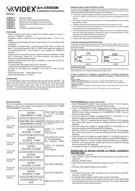
MODELS:<br />
VX800N-2<br />
VX800N-2L<br />
VX800N/F<br />
VX800N/S<br />
VX800N-3<br />
VX800N-3L<br />
Art.VX800N<br />
Installation <strong>Instructions</strong><br />
Module 2 Relay<br />
Module 2 Relay plus panel illumination<br />
Stand alone unit 2 Relay. Flush mounting<br />
Stand alone unit 2 Relay. Surface mounting<br />
3 Relay<br />
3 Relay plus panel illumination<br />
FEATURES<br />
Access control system with 2 codes and 2 Relay outputs (3 codes, 3<br />
relays on VX800N-3.. version).<br />
Engineer’s code to enter into the “Programming Menu” ( from 4 to 8<br />
digits).<br />
Programming of the activation time of each relay from 1 up to 99 seconds<br />
or latching.<br />
Possibility to activate relay 1 by shorting terminal ”SW1” to GND and<br />
relay 2 by shorting terminal “SW2” to GND. Both relays will operate for<br />
the programmed time ( this feature is not available on VX800N-3<br />
version).<br />
Keypad gives an acoustic (buzzer) signal during the entering of codes<br />
and a continuous melody for 4 or more seconds, according to the<br />
number of mistakes (self protection).<br />
Keypad includes panel illumination (VX800N-..L only) and 2 LED’s to<br />
show the following:<br />
Correct relay code (green LED on for 2 seconds).<br />
Red LED to indicate when in the “programming menu”.<br />
Contacts of the relays are available ( N.O and N.C) with 5A max<br />
24Vac/dc.<br />
Power requirements: 12/24VAC/DC, 2VA.<br />
Working temperature: -10 +50°C<br />
OPERATION<br />
To use the system, type in the programmed code and press “ENTER” , the<br />
green LED will illuminate and the relay will operate for the programmed<br />
time.To cancel remain open time, type in the same code and press<br />
“CLEAR”. If a wrong code is entered, a continuous melody will sound for 4<br />
or more seconds, according to the number of mistakes.<br />
GENERAL DIRECTIONS FOR INSTALLATION<br />
In order to achieve the best results from the schematics described it is necessary to<br />
install only original VIDEX equipment, strictly keeping to the items indicated on each<br />
schematic and follow these General Directions for Installation:<br />
The system must be installed according to national rules in force, in any case the<br />
running of cables of any intercom unit must be carried out separately from the<br />
mains;<br />
All multipair cables should be compliant to CW1308 specification (0.5mm twisted<br />
pair telephone cable.<br />
Cables for speech line and service should have a max resistance of 10<br />
Lock release wires should be doubled up (Lock release wires and power supply<br />
wires should have a max resistance of 3 );<br />
The cable sizes above can be used for distances up to 50m. On distances above<br />
50m the cable sizes should be increased to keep the overall resistance of the<br />
cable below the RESISTANCES indicated above;<br />
Double check the connections before power up;<br />
Power up the system then check all functions.<br />
LOCK RELEASE BACK EMF PROTECTION<br />
A capacitor must be fitted across the terminals on AC lock release (Fig.1A) and a<br />
diode must be fitted across the terminals on a DC lock release (Fig.1B) to suppress<br />
back EMF voltages.<br />
Connect the components to the lock releases as shown in figures.<br />
Fig.1A<br />
Fig.1B<br />
BUZZER BACK EMF<br />
When using intercoms with buzzer call (Art.924/926, SMART1/2, 3101/2, 3001/2 and<br />
3021/2) add one 0,1uF capacitor between terminals 6 and 3.<br />
If help is required for installing or operating this unit please contact our<br />
technical department on +39 0734 631669 (all countries) or +44 0191 224 3174<br />
(UK).<br />
Factory - Office<br />
VIDEX ELECTRONICS S.p.A. Via del lavoro,1 63020 MONTEGIBERTO (AP) - ITALY<br />
Phone: (+39) 0734 - 631669 Fax: (+39) 0734 - 632475 www.videx.it e-mail: info@videx.it<br />
Northern UK Office<br />
VIDEX LTD Unit 4-7 Chillingam Industrial Estate Chapman Street NEWCASTLE UPON TYNE<br />
Ne6 2XX<br />
Phone: (+44) 0870 3001240 Fax: (+44) 0191 - 2241559 www.videx-security.com<br />
INITIALIZATION<br />
When the installation is concluded and carried out according to the wiring<br />
diagram, power up the system and program it by following the “VX800<br />
PROGRAMMING” Flow Chart.<br />
Press Enter<br />
(Red LED will be<br />
ON)<br />
Press Enter<br />
(Melody)<br />
Press Enter<br />
(Melody)<br />
Press Enter<br />
(Melody)<br />
Press Enter<br />
(Melody)<br />
Press Enter<br />
(Melody)<br />
Press Enter<br />
(Melody)<br />
Press Enter<br />
(Melody)<br />
ENTER<br />
“ENGINEER’S CODE”<br />
CONFIRM OR CHANGE<br />
“ENGINEER’S CODE”<br />
ENTER<br />
“ACCESS 1 CODE”<br />
ENTER<br />
“ACCESS 1 TIME”<br />
ENTER<br />
“ACCESS 2 CODE”<br />
ENTER<br />
“ACCESS 2 TIME”<br />
ENTER<br />
“ACCESS 3 CODE”<br />
ENTER<br />
“ACCESS 3 TIME”<br />
SYSTEM READY TO<br />
USE<br />
FIRST TIME SIX TIMES<br />
1 “111111” FACTORY<br />
PRESET<br />
TYPE AGAIN SIX TIMES “1” OR<br />
THE NEW ENGINEER’S CODE<br />
4 TO 8 DIGITS<br />
CODE TO ENABLE<br />
RELAY 1<br />
4 TO 8 DIGITS<br />
TWO DIGITS (01 TO 99)<br />
I.E. 05=5 SECONDS<br />
00= REMAIN OPEN<br />
CODE TO ENABLE<br />
RELAY 2<br />
4 TO 8 DIGITS<br />
TWO DIGITS (01 TO 99)<br />
ONLY 800-3 VERSION<br />
ONLY 800-3 VERSION<br />
RED LED WILL BE OFF<br />
PROGRAMMING(refer also to flow chart)<br />
Enter “ENGINEER’S CODE”: first time type six times “1” (111111 factory<br />
preset) and press ENTER (The red LED will illuminate).<br />
Confirm “ENGINEER’S CODE” (typing again the same) or type the new<br />
code (4 to 8 digits) then press ENTER (Melody). Pressing twice the<br />
ENTER button without changing the “ENGINEER’S CODE”, will exit<br />
from the programming.<br />
Enter the code (4 to 8 digits) to enable “RELAY 1” (ACCESS 1) or reenter<br />
the existing code then press ENTER (Melody).<br />
Enter the “RELAY 1” operation time (2 digits 01 to 99 I.E. 05=5 seconds,<br />
00= remain open time) or re-enter the existing time then press ENTER<br />
(Melody).<br />
Enter the code (4 to 8 digits) to enable “RELAY 2” (ACCESS 2) or reenter<br />
the existing code then press ENTER (Melody).<br />
Enter the “RELAY 2” operation time (2 digits 01 to 99 I.E. 05=5 seconds,<br />
00= remain open time) or re-enter the existing time then press ENTER<br />
(Melody).<br />
Enter the code (4 to 8 digits) to enable “RELAY 3” (ACCESS 3 only for 3<br />
relay models) or re-enter the existing code then press ENTER (Melody).<br />
Enter the “RELAY 3” (only for 3 relay models) operation time (2 digits 01<br />
to 99 I.E. 05=5 seconds, 00= remain open time) or re-enter the existing<br />
time then press ENTER (Melody).<br />
The system is ready to use (the red LED will be off).<br />
INSTRUCTION TO RETURN SYSTEM TO PRESET ENGINEER’S<br />
FACTORY CODE<br />
Turn off power to code lock.<br />
Keep “ENTER” button pressed while turning back on the power to the<br />
code lock.<br />
Release “ENTER” button.<br />
The master code is now set at factory engineer’s code “111111” (six times<br />
“1”).<br />
Proceed with programming for a new system.<br />
NOTES<br />
To switch off any relay while operating, type in the relevant code then<br />
press the “CLEAR” button.<br />
To operate relays together, set the same code for each relay.<br />
If a wrong code is entered, the system will lock out for 5 seconds which<br />
will increase each time a wrong code is entered. The system will operate<br />
only when the correct code is entered.
RE-PROGRAMMING GUIDE<br />
Press Enter<br />
(Red light will<br />
illuminate*)<br />
Press Enter<br />
Press Enter<br />
Press Enter<br />
Repeat steps for<br />
relay 2 and 3<br />
ENTER THE<br />
ENGINEER’S CODE<br />
RE-ENTER THE<br />
ENGINEER’S CODE<br />
ENTER ACCESS CODE<br />
ENTER ACCESS TIME<br />
More<br />
DOORS ?<br />
YES<br />
NO<br />
PRESS ENTER TWICE TO<br />
EXIT PROGRAMMING<br />
ALTERNATIVELY ENTER<br />
A NEW ENGINEER’S<br />
CODE (4 TO 8 DIGITS)<br />
RELAY CODE (4-8 DIGITS)<br />
OPERATE THE DOOR OR<br />
GATE.**<br />
TWO DIGITS (01-99 Sec<br />
OR 00 FOR REMAIN<br />
OPEN)<br />
RED light will<br />
switch OFF<br />
Notes:<br />
* If the red light does not illuminate, the engineer’s code is incorrect. Follow<br />
instructions to return system to preset engineer’s factory code.<br />
** On the first loop of the flow chart its relay 1, second loop is relay 2 and the<br />
third loop is relay 3.<br />
Engineer’s Code<br />
Relay 1 Code<br />
Relay 2 Code<br />
Relay 3 Code<br />
Relay 1 Time<br />
Relay 2 Time<br />
Relay 3 Time<br />
18/12/2006