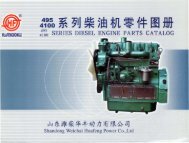
HUAFENGDONGLI 4102 Series Diesel Engine Operation And - Rotek
HUAFENGDONGLI 4102 Series Diesel Engine Operation And - Rotek
HUAFENGDONGLI 4102 Series Diesel Engine Operation And - Rotek
You also want an ePaper? Increase the reach of your titles
YUMPU automatically turns print PDFs into web optimized ePapers that Google loves.
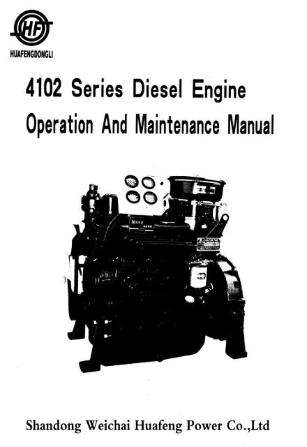
<strong>HUAFENGDONGLI</strong><br />
<strong>4102</strong> <strong>Series</strong> <strong>Diesel</strong> <strong>Engine</strong><br />
<strong>Operation</strong> <strong>And</strong> Maintenance Manual<br />
Shandong Weichai Huafeng Power Co.,Ltd
Preface<br />
HUAFENGDONGU brand <strong>4102</strong> series diesel engine is a four - stroke, water - cooled,<br />
inline and direct injecting combustion chamber type, high - speed diesel engine. <strong>4102</strong> series<br />
is bore - enlarged from 95 series.<br />
In 1980s our company adopted the comet V combustion<br />
system and diesel design technique of Ricardo Consulting <strong>Engine</strong>ers Company and have made<br />
great improvement in design. This type diesel engine possesses perfonnances of high power,<br />
economy and liability, and reaching a advanced level among the same kinds products all over<br />
the world.<br />
The National Science Congress prized HUAFENGDONGU brand <strong>4102</strong> series diesel engine<br />
and it is easy to adapt. According to the different application, through being changed for<br />
some of its parts accordingly, it can be llsed to match with middle tractors, engineering machinery,<br />
middle vehicles, generating sets, inigating machinery and agricultural machinery<br />
and so on..<br />
<strong>4102</strong> series is developed from 495 series, main parts are reinforced, Electrical<br />
system, Inlet system, Exhaust system, Cooling system have improved, and the output range<br />
is enlarged. ZH<strong>4102</strong> is developed from K<strong>4102</strong>. It adopts the direct injecting combustion<br />
chamber, and improved its economy further. The model, its make - up role and the meaning<br />
of the symbol for every type is as follows:<br />
ZH<br />
4<br />
102<br />
o<br />
o<br />
@<br />
o<br />
o<br />
@<br />
0--0<br />
K 4 102 0--0<br />
(]) @ @<br />
~ 00<br />
00: Distinguish symbol, Expressed with number sequence<br />
~: Version symbol, expressed with number sequence<br />
@:Application feature symbol, expressed with alphabet<br />
No alphabet: for common use; T: for tractor; G: for engineering machinery; Q: for vehicle;<br />
D: for generating set; C: for marine use; P: for power take - off unit; Y: for transporting<br />
vehicle use.<br />
@: Construction feature symbol, expressed with alphabet; no alphabet: for natural aspirated<br />
model; Z: for turbocharged model.<br />
®:Cylinder bore (nun)<br />
@:Cylinder number<br />
(J): Cylinder expanded (ZH: Direct injecting combustion chamber)<br />
period maximally, reduce the cost of usage, we compiled this manual on the basis of the "<br />
Nation Rated 495 <strong>Diesel</strong> <strong>Engine</strong> Manual" and the change and improvement of products to in-
troduce the operation and maintenance knowledge to the customers.<br />
This operation manual mainly introduces common usage type. For the products is changing<br />
and improving continually t there may be some slight difference between the products and<br />
that described in this manual and the users are advised to notice it kindly.<br />
The manual is complied by Yu Caihong, Wei Yunfeng, Zhao Ruian, Wang Jinghai, and<br />
Sun Chu~ai.<br />
HUaiq(~/<br />
Advised by Li Peiyan, Chen ling, and finally examined and approved by Li<br />
For the limit of the compilers, there may be some mistakes in the manual, if you find<br />
any, please point out so that we can be corrected.<br />
The compiler<br />
November 2005
Attention<br />
1. The diesel engine operators must familiarize themselves with this manual as well as engine<br />
comstIUction and strictly' follow the procedures of operation and maintenance especially the<br />
regulations for safety opera - lion described in this manual.<br />
2. Before operating an engine at full load, the 60 hours running in should be carried out as<br />
specified in the manual.<br />
3. Increase its speed gradually after stating a cold engine, never let it ron at highs speed abruptly,<br />
and dont stop the engine instantly while its cooling water is still hot, also don f let<br />
the engine running long time without load.<br />
4. H the ambient temperature falls below +S'C ,drain the cooling water out of the radiator,<br />
the lubricating oil cooler and the diesel engine itself completely after stopping the engine.<br />
Con - tinuous keeping the water in the oil cooler should be forbid - den.<br />
s. Never ron the diesel engine without and air cleaner so as to prev~nt the unfiltered air from<br />
entering the cylinders.<br />
6. The engine must be filled with specified grade fuel and lubri - eating oil,and a special and<br />
clean container for each oil should be used. The fuel oil should be settled for 72 hours and<br />
fil - tered before using.<br />
7. The inspection and repair of the components in electrical sys - tern must be carried out by<br />
the person who 'has a good knowledge of electricity.<br />
8. The working environment of the diesel engine should he well ventilated to avoid being polluted<br />
by waste gas or smoke.<br />
9. The power rating and amending of the diesel engine is ac - cording to GB6072. 1 - 2000<br />
the first section of reciprocating internal combustion engine: standard. basic condition, the<br />
rating and testing method of power, fuel consumption and engine oil consumption.<br />
10. The manufacturing of the diesel engine is according to the common technical requirement<br />
for low and middle level powered diesel engine in JB/T8895 -1999 and Q/WHFOO2 <br />
2005 495 series diesel engine enterprise standard.<br />
11. The No. of production license of this series diesel engine is:XK06 -205 -OOS24,XK06<br />
- 205 - 00279 0<br />
12. The position of safety warning marks:<br />
( 1 ) Theres guard. against burning mark at the end of the cylinder cover which is beside<br />
the exhaust manifold of the diesel engine.<br />
( 2 ) Theres a guard against fire mark at the oil filler.<br />
( 3 ) Theres a guard against twinning mark on the inlet man - ifold.
o<br />
N<br />
CO<br />
680<br />
828.5<br />
320<br />
600<br />
9-M12<br />
depth 19<br />
Outline. .dra:wift.f; for 1:111020 dioool onlY-no<br />
• 1 •
ge<br />
g/kW."h<br />
450<br />
420<br />
390<br />
360<br />
330<br />
300<br />
270<br />
240<br />
\<br />
\ \<br />
1 \<br />
~ \<br />
1500r/min<br />
1\ '<br />
V~<br />
~<br />
\ ~~ V"<br />
",1 \<br />
,<br />
1800r/min<br />
\ \ v v<br />
~<br />
\<br />
\ ~<br />
v<br />
,<br />
\<br />
V ~\<br />
\ \ 1\ /v<br />
\<br />
~ \<br />
\<br />
k'<br />
'\ '\ "<br />
~ f'..<br />
'" '" ~ ""~<br />
2000r/min<br />
" '""<br />
~<br />
r---.....<br />
r------....<br />
~ --. ~ ---<br />
I---.<br />
~ r----. ~ -<br />
10 15 20 25 30 35 40 pe kW<br />
Load characteristic curve for 1500,1800 ,<br />
2OOOr/min diesel engine<br />
• 2 •
<strong>4102</strong> Main Technical Specifications<br />
NO<br />
~<br />
1 Type<br />
2<br />
3<br />
Cylinder No. - Bore * Stroke<br />
(mm)<br />
Total Displacement of Piston<br />
(L)<br />
<strong>4102</strong> K<strong>4102</strong> K<strong>4102</strong>G K<strong>4102</strong>P ZH<strong>4102</strong>D<br />
Four strokes, Water Cooling, Inline,<br />
Swirl combustion chamber<br />
4 - -102 x 115<br />
3.76<br />
4 Pressure Ratio 19:1<br />
5 Firing Order 1-3-4-2<br />
6 Air Intake Mode Naturally Aspirated<br />
Ih Output 1<br />
Speed 44/2000 36.3/1500 46.6/2400 44/2000 36.3/1500<br />
Rated ( kW/r/min)<br />
7 Working<br />
Condition 12h Output 1<br />
Speed 40/2000 33/1500 40/2000 33/1500<br />
( kW/r/min)<br />
8<br />
9<br />
10<br />
Highest Idling Speed<br />
(r/miD)<br />
Lowest Idling Stable Speed<br />
( r/min)<br />
Max Torque/Speed<br />
(N. mlr/min)<br />
~2160 ~1575 ~2640 ~2160 ~1575<br />
~550<br />
219/1500 213/1680 219/1500<br />
Average<br />
11<br />
Effective 650 702 620 650 702<br />
I---<br />
Pressure( Kpa)<br />
12 Fuel<br />
Rated Consumption Rate ~258.4 ~266.6 ~258.4<br />
--- Working (g/kW. h)<br />
13 Condition<br />
Oil Consumption<br />
~2.04<br />
--- Rate{glkW. h)<br />
14<br />
Exhaust<br />
=::;;600<br />
temperature( CC )<br />
15 Crankshaft Rotating Direction Anti - clockwise (Facing to the power output end)<br />
16 Cooling Mode Forced Water Cooling<br />
17 Lubricating Mode Compound type with pressure and splash<br />
18 Startin2 Mode Electric startine<br />
19 Net Mass{ kg) 320 380 340 450 380<br />
• 3 •
Various temperature and pressure range<br />
Oil temperature<br />
Outlet cooling water temperature<br />
Oil pressure<br />
Fuel injection pressure<br />
~ l00'C ( the TC <strong>Engine</strong>)<br />
=s;:95'C (naturally aspirated)<br />
~98~(the TC <strong>Engine</strong>)<br />
===90CC (naturally aspirated)<br />
0.20 -0. 40MPa<br />
~O. 5MPa,when at idling speed<br />
12 +1.°MPa<br />
Main bolts tightening torque<br />
Cylinder head bolt<br />
Main bearing bolt<br />
Flywheel tightening bolt<br />
Connecting rod bolt<br />
Gear case bolt<br />
Flywheel housing bolt<br />
160 -180N. m (Direct injecting: 190 - 210)<br />
160 -180Na m<br />
100 -120N. m<br />
100 -120N. m<br />
30 -40N. m<br />
50 -60N. m<br />
Main adjusting data<br />
Valve lash( cold state)<br />
Air intake & exhaust valve<br />
Valve timing:<br />
Air intake valve open<br />
Air intake valve open<br />
Exhaust valve open<br />
Exhaust valve open<br />
Compression clearance<br />
Fuel delivery advance angle:<br />
1500 - J600r/min<br />
1800 -2000r/min<br />
2400r/min<br />
0.35 -O.45mm<br />
12 a :t:: 3 6 hefore top dead center<br />
36 lt ± 3 a after bottom dead center<br />
S6 a ± 3 6 before bottom dead center<br />
12a ± 3 a after top dead center<br />
1 -1.2mm<br />
15 a ± 2 0 before top dead center<br />
17 a ± 2° before top dead center<br />
• 4 •
Matched clearances and wear limit of main parts<br />
NO Matched parts Standard size Matched clearance Wear limit<br />
o .<br />
Crankshaft main journal neck Shaft cf)75· - o. 019<br />
1<br />
O. 070 - O. 154 0.30<br />
and main bearing<br />
Hole 4l 75:g:~<br />
2<br />
Crankshaft thrust ring and<br />
Axial clearance<br />
crankshaft 0.080 -0.230<br />
0.50<br />
Crankshaft & connecting rod Shaft 65 ~0.019<br />
3 journal neck and connecting<br />
bearing<br />
Hole 38 ~O.lOO 0.170 -0.430<br />
0.70<br />
5<br />
Piston skirt and cylinder liner<br />
Shaft 102 :g:}jg<br />
Hole 2. 5 ~O. 01S<br />
Hole 2.5:g:=<br />
0.040 -0.075 0.30<br />
9 Oil ring and ring grave<br />
Shaft 4>5 ~O.OIS<br />
H I 5 +O.O~<br />
o e +0.030<br />
0.030 -0.065 0.25<br />
10<br />
Gap of first compression ring Gauge within102.00 O. 250 - O. 500 3.00<br />
in cylinder -0. 1<br />
11<br />
Gap of second & third<br />
compression ring in cylinder<br />
Gauge within102.00 0.200 -0.450 3.00<br />
12 Gap of oil compression ring in Gauge within102.00 0.200 -0.450 3.00<br />
cylinder<br />
13<br />
CnInohoIt. journul neok and<br />
Shaft 50 - 0.080<br />
-0. lOS<br />
bushing<br />
0.0l!.0 - O. 130 0.2..:)<br />
Ho~e
NO Matched· parts Standard size Matched clearance Wear limit<br />
14<br />
Camshaft thrust plate<br />
and camshaft<br />
Shaft 4'12 :g:~<br />
Hole 4» 12 +00' 100<br />
O. 050 - O. 220 0.40<br />
15<br />
Cylinder liner over the<br />
cylinder block surface<br />
Shaft 4»10 ~o.oso <strong>Engine</strong> body projection<br />
Hole 16 ~0.018<br />
O. 016 - 0.052 0.20<br />
17<br />
18<br />
Idler shaft and idler Shaft 26 :g:~<br />
shaft bushing<br />
Hole W 26 ~o.021<br />
Shaft 9 -0.030<br />
Air intake valve and<br />
-o.mo<br />
valve guide Hole 9 ~0.022<br />
0.020 -0.062 0.20<br />
0.030 -0.072 0.25<br />
19<br />
Exhaust valve and<br />
Shaft 9 -0.040<br />
-0.060<br />
valve guid~ Hole fIl 9 +0.022<br />
. 0<br />
0.040 -0.082 0.25<br />
20<br />
Rocker ann shaft<br />
and bushing<br />
Shaft cl»16 -0.016<br />
-0.034<br />
Hole W 16 ~0.OI8<br />
0.016 - 0.052 0.25<br />
21 Idler and idler shaft<br />
Axial clearance<br />
0.100 -0.350<br />
22<br />
Contacting clearance of<br />
K:learance of tooth flam<br />
various timing gear 0.130 -0.170<br />
23<br />
Oil pump rotor and pump<br />
Adjusting clearance<br />
block surface 0.050 -0.100<br />
24<br />
Contacting clearance<br />
between the oil pump<br />
0.060 - O. 188 0.50<br />
25<br />
Water pump impeller<br />
Back clearance<br />
and pump body 0.200 -0.700<br />
26<br />
Water pump impeller<br />
Adjusting clearance<br />
and packing block 0.400 - o. 800<br />
· 6 ·
Electrical System<br />
<strong>4102</strong> series diesel engines have 12V and the 24V two kinds of electrical systems. For<br />
one wire system cathode earth. In the electrical system the electrical machinery rated voltage<br />
and the electric appliance rated voltage must tally with the electrical system voltage.<br />
The battery used for getting up is the diesel engine power equipment, Its penonnance affects<br />
the diesel engine directly the starting, According to the starting motor characteristic<br />
choices stipulation capacity of storage battery, the battery installs the position to have to approach<br />
the starting motor as far as possible, in order to reduce between the accumulator cell<br />
and the starting motor the connecting lead length, preventing when starting' the line pressure<br />
drop oversized. The connecting lead uses 35 square millimeter low - tension wires. Regarding<br />
12Vand 14V starting motor, when the starting current is biggest, the line pressure drop<br />
should not to be bigger than O. 5V and IV.<br />
The battery has not charged, before the use you must carry on the initial charge according<br />
to the battery request. In the diesel engine generating, you should pay attention to the<br />
charging current frequently the size, when the ampere meter indicated value approaches "0" ,<br />
it expressed ~e battery already filled the electricity, and you may shut off the charging circuit.<br />
The generator uses the JF series silicon rectification generator. The silicon rectification<br />
generator has the volume to be small, the structure to be simple, and the low speed charge<br />
perfonnance to be good and so on. On the generator top plate is loaded with two groups of silicon<br />
rectifier cell. The alternating current outputs which by three groups of windings passes<br />
through the three - phase bridge type full - wave rectification tum to direct current, by " +"<br />
wiring column outputs. Dont allow with the way which striking a light to earth inspects whether<br />
generates work normally, preventing the silicon rectifier cell hurning out.<br />
The voltage regulator function is that the voltage will be ~utomatic the output voltage t~<br />
stabilize in 13.5 -14. 5V or in the 27 - 29V scope when the rotational speed of 14V generator<br />
or 28 V generator changes. These two kinds of generators separately match FrIll and the<br />
FT211 regulator. IT you need to meet the battery control lamp, you change the Ff126 and the<br />
Ff226 regulator. When using the Frill and the Ff211 regulator, you should cut the battery<br />
after the engine off inunediately, Prevents the battery to the field coil electric discharge, the<br />
starting of diesel engine will effect next time. The regulator is the precision electric appliance.<br />
Do not have to disassemble the adjusbnent generally, when it is necessary to adjust on<br />
the special purpose equipment.<br />
Starting motor is a totally enclosed direct current series motor. The starting motor revolves<br />
electric current oversized, only pennits the short time work t each time starting time<br />
does not have to surpass lOs. If you must start continuously t<br />
the time interval does not have to<br />
• 7 •
he smaller than 2min,and starting the number of times does not to be supposed continuously<br />
to surpass 10 times generally, in order to avoid damage starting motor and battery.<br />
I<br />
lJ -1!_ cdntoctor<br />
r"Y neuc : Blue 600 1mm 2<br />
L _--..J5tOrting~ .. _ .. _ .. _ ..<br />
ery M I I --+----<br />
.. ---'<br />
Blue line 1mm 2<br />
Brock line 2.5mm 2<br />
White line 1mm 2<br />
Oil temperature sensor<br />
Water temperature sensor<br />
Electrical system schematic drawing<br />
<strong>4102</strong> series diesel engine has used the inductance measuring<br />
appliance, when using the meter the power source should use<br />
the 14V direct - current power supply or the battery.<br />
The circuit key switch has three working positions. The key turns clockwise to put<br />
through the preheating starting switch, the voltage regulator and other electric appliances, the<br />
diesel engine may start at. Mter th~ diesel engine is started the key should tum anti - clockwise<br />
extension, at the same time you should shut off the preheating starting switch, in order<br />
to avoid the accident.<br />
The preheating starting switch has four working positions. Turning to "preheating" only<br />
puts through the pre - heater, if you tum to " the preheating starting" , it may preheat and<br />
~tart. IT you do not nc;c;d pcc;hc;atin6 ~ou can turn to •• me :nllninr;·· dicecdy. ,The switch should<br />
automatically return to "0" after loosing your hand and the key - off.<br />
· 8 ·
Instaii schematic drawing of foundation and radiator<br />
for <strong>4102</strong>D series generates electricity diesel<br />
Shoch<br />
absorber<br />
I I I I<br />
;+.,. ;+.,.<br />
I""t-\<br />
......., ......., L---------<br />
"-J<br />
II<br />
II<br />
1<br />
r<br />
0<br />
N<br />
-<br />
I<br />
c.o co I<br />
~<br />
........-<br />
I<br />
I -<br />
0 C"'-J<br />
I co<br />
II<br />
1<br />
CD LO<br />
R7 I ........- -..r--"<br />
, ~<br />
8 sectiOf\ - f""-...<br />
J<br />
I<br />
C'l<br />
i<br />
\<br />
}II h.- ~rlh. 1""'\<br />
---------<br />
"'lV<br />
"IV<br />
10<br />
4section 80 125 680<br />
I<br />
I<br />
"'~<br />
tq<br />
C'J<br />
~<br />
""<br />
\ 4-lb18<br />
Note: the size in parenthesis are install hole distance<br />
when adopt welds front support<br />
• 9 ·


