


Create successful ePaper yourself
Turn your PDF publications into a flip-book with our unique Google optimized e-Paper software.
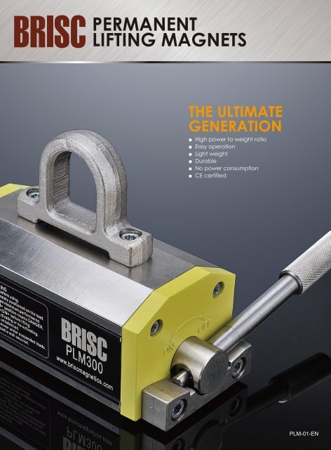
<strong>PERMANENT</strong><br />
<strong>LIFTING</strong> <strong>MAGNETS</strong><br />
THE ULTIMATE<br />
GENERATION<br />
■ High power to weight ratio<br />
■ Easy operation<br />
■ Light weight<br />
■ Durable<br />
■ No power consumption<br />
■ CE certified<br />
PLM-01-EN
THE BEST<br />
Show of<br />
FORCE.<br />
The complete choice for industrial lifting<br />
Soph specializes in permanent, electro-permanent and electro-magnetic<br />
technology covering the entire range of magnetic technology available on<br />
the market today. With more than 15 years experience and thousands of<br />
installations worldwide Soph will always offer the best technology for the<br />
application to meet our customer’s needs.<br />
<strong>PERMANENT</strong> <strong>LIFTING</strong> <strong>MAGNETS</strong>
THE ULTIMATE<br />
GENERATION<br />
The most practical, safe and economical way to<br />
handle ferrous loads.<br />
Hundreds of thousands of units are already in<br />
use all over the world confirming the great value<br />
of magnetic lifters each and everyday in many<br />
industrial sectors such as:<br />
- Tool and die shops<br />
- Machinery Builders<br />
- Steel fabrication shops<br />
- Steel distribution centers<br />
- Shipyards and Ports<br />
- Foundries and Steel mills<br />
- Construction<br />
- Warehousing and transportation
■ With safety, there is no room to play.<br />
Each lifter is tested to certify the real<br />
force is no less than 3X declared<br />
safe working load (SWL) and that the<br />
air gap curve is accurate.<br />
EXCLUS<br />
The best expression of power<br />
Through a qualitative selection process of top grade high energy magnets<br />
and high dimensional tolerances between the stator and rotor we have<br />
achieved a 20% higher rated force in the same size. This allows us to offer<br />
the same size magnets with more lifting capacity.<br />
Greater flexibility with thin gage loads<br />
PLM series magnets have been designed to meet the demand<br />
for handling thin loads in a safe and efficient way.<br />
The special design of the polar area together with a properly balanced<br />
magnetic field allows a lower flux depth. The properly balanced magnetic<br />
field allows for easier handle operation on thinner plates.<br />
Reliability<br />
The on and off cycle is performed by simply turning a lever. The<br />
high tolerance bearing surface in the lifter is designed for years of<br />
service.<br />
Permanently safe power<br />
High energy permanent magnets ensure great force and with<br />
good design we achieve concentrated power indefinitely. The 3X<br />
safety factor rating allows safe working conditions even with<br />
substantial air gaps.<br />
N<br />
S<br />
N<br />
S<br />
N<br />
S<br />
S<br />
N<br />
■ “Safety first” with the spring loaded safety handle design which<br />
prevents accidental de-mag.<br />
■ High power Neodymium magnets and the Isolated magnetic circuit<br />
design ensure a high power to weight ratio.<br />
■ With the maintenance free design, nickel plated steel parts the PLM<br />
lifter will provide a long lasting trouble free operational life.<br />
■ Advanced machining processes with stringent testing requirements<br />
ensures each Brisc lifter has the same strength and overall quality.<br />
Mag phase<br />
Durable and compact<br />
Demag phase<br />
The incredible power to weight ratio is provided by the specific<br />
isolation design and high tolerance parts.<br />
Product innovation, material selection and state of the art<br />
manufacturing processes have created a powerful product with no<br />
maintenance requirements and convenient pricing resulting in great<br />
international success making PLM the best selling close proximity<br />
lifter on the market.
IVE technology<br />
with UTMOST SAFETY.<br />
Best performances with suitable loads<br />
All magnetic performances are directly related to the actual size and shape of the load to be<br />
handled. In addition, air gaps, temperature, metallurgical composition and thickness of the<br />
load all play key roles in the performance of a specific magnet.<br />
Air gap vs Power<br />
The performance with irregular<br />
shaped loads that create a High air<br />
gap makes the Isolated magnetic<br />
circuit design shine above all other<br />
lifters with the same weight and<br />
size. With the isolated flux path<br />
design, the largest air gaps can be<br />
overcome relative to the quantity<br />
of magnetic materials in the lifter.<br />
AIR GAP (mm)<br />
Pull/Air gap curves on common Fe 370B<br />
with steel poles completely covered.<br />
(functional parameters)<br />
Force to material<br />
Common<br />
steel<br />
Medium alloyed<br />
steel<br />
Alloyed<br />
steel<br />
Cast<br />
iron
the ADVANCED<br />
manufacturing process<br />
The best show of force<br />
Due to the use of neodymium magnetic material these lift<br />
magnets have an enormous power to weight ratio. EXAMPLE:<br />
the PLM 300 has an actual break away force of 60 times it’s<br />
own weight.. The lifting magnets can easily be switiched by<br />
hand in case its magnet circlit is closed when the magnet is<br />
places on the workpiece.<br />
Greater flexibility, thin gage loads<br />
PLM series magnets have been designed to meet the demand<br />
for handling thin loads in a safe and efficient way.<br />
The special design of the polar area together with a properly<br />
balanced magnetic field allows a lower flux depth. The properly<br />
balanced magnetic field allows for easier handle operation on<br />
thinner plates.<br />
Force to thickness<br />
16000<br />
14000<br />
PLM-5000<br />
12000<br />
11000<br />
10000<br />
9000<br />
PLM-3000<br />
Force (daN)<br />
8000<br />
7000<br />
6000<br />
PLM-2000<br />
5000<br />
4000<br />
3000<br />
PLM-1000<br />
2000<br />
1000<br />
0<br />
10<br />
20<br />
30<br />
Load<br />
thickness (mm)<br />
40<br />
50<br />
60<br />
70<br />
80<br />
90<br />
PLM-500<br />
PLM-250<br />
SAFER-125
Operation sequence<br />
1<br />
Handle locked in “OFF” position<br />
2<br />
Pull out the handle<br />
3<br />
Turn the handle<br />
4<br />
Handle in “ON” position<br />
5<br />
Handle locked in “ON” position<br />
Concentrated power<br />
The Key elements for high power is the complete isolation of the<br />
north and south poles through the stator and rotor forcing all<br />
potential magnetic lines of flux through the part only with none<br />
being diverted through the frame of the lifter before reaching the<br />
part itself. This insures the customer gets all the power they paid<br />
for, where they need it, when they need it, for years to come.<br />
This design allows for the highest power to weight ratio in the<br />
industry.<br />
A revolutionary design<br />
The PLM series lifting magnet is an innovative design as a result of<br />
many successful lifting systems from Soph. in the development of<br />
application specific solutions in the permanent magnet lifting field.<br />
SAFETY<br />
and SIMPLICTY<br />
up front.
Specifications<br />
G<br />
H1<br />
F<br />
H2<br />
B<br />
L<br />
B1<br />
Features:<br />
compact and light<br />
at least 3 safety factor<br />
suitable for flat and round material<br />
maintenance free design<br />
safety device prevent accidental deactivation<br />
can be switched off by one hand only<br />
Model Size Safe Working Load Width LengthH1 H1 H2 B1 F G Net Weight<br />
PLM 100 100 kg/220 Ib 70 (2.76) 130 (5.12) 60 (2.36) 53 (2.09) 176 (6.93) 35 (1.38) 28 (1.10) 3.5 kg/8 Ib<br />
PLM 300 300 kg/660 Ib 95 (3.74) 205 (8.07) 83 (3.27) 70 (2.76) 220 (8.66) 47 (1.85) 40 (1.57) 10 kg/22 Ib<br />
PLM 600 600 kg/1320 Ib 125 (4.92) 272 (10.71) 104 (4.09) 95 (3.74) 296 (11.65) 64 (2.52) 50 (1.97) 23 kg/51 Ib<br />
PLM 1000 1000 kg/2200 Ib 160 (6.30) 318 (12.52) 140 (5.51) 95 (3.74) 410 (16.14) 64 (2.52) 50 (1.97) 44 kg/97 Ib<br />
PLM 2000 2000 kg/4400 Ib 160 (6.30) 496 (19.53) 140 (5.51) 120 (4.72) 508 (20.00) 80 (3.15) 60 (2.36) 72 kg/158 Ib<br />
PLM 3000 3000 kg/6600 Ib 230 (9.06) 510 (20.08) 212 (8.35) 155 (6.10) 600 (23.62) 100 (3.94) 70 (2.76) 160 kg/352 Ib<br />
PLM 5000 5000 kg/11000 lb 360 (14.17) 725 (28.54) 261 (10.28) 180 (7.09) 980 ( 38.58) 100 (3.94) 70 (2.76) 450 kg/990 lb<br />
Model Size Load Plate Max Plate Min Thickness Plate Max Length Load Round Max Round Min Thickness Round Max Diameter<br />
PLM 100 100 kg/220 Ib 15 (0.59) 1000 (39.37) 40 kg/88 lb 8 (0.31) 150 (5.9)<br />
PLM 300 300 kg/660 Ib 20 (0.79) 1500 (59.06) 120 kg/264 lb 12 (0.47) 180 (7.09)<br />
PLM 600 600 kg/1320 Ib 25 (0.98) 2000 (78.74) 240 kg/528 lb 20 (0.79) 250 (9.84)<br />
PLM 1000 1000 kg/2200 Ib 40 (1.57) 3000 (118.11) 400 kg/880 lb 25 (0.98) 280 (11.02)<br />
PLM 2000 2000 kg/4400 Ib 55 (2.17) 3000 (118.11) 800 kg/1760 lb 35 (1.38) 350 (13.78)<br />
PLM 3000 3000 kg/6600 Ib 70 (2.76) 3500 (137.8) 1200 kg/2640 lb 45 (1.77) 400 (15.75)<br />
PLM 5000 5000 kg/11000 lb 85 (3.35) 4000 (157.48) 2000 kg/4400 lb 55 (2.17) 450 (17.7)
Functional parameters<br />
minimum thickness 15mm<br />
100<br />
300<br />
LOAD(Kg)<br />
50<br />
150<br />
Force(daN)<br />
PLM100<br />
0<br />
0.5<br />
AIR GAP(mm)<br />
1.0<br />
minimum thickness 20mm<br />
LOAD(Kg)<br />
300<br />
150<br />
900<br />
450<br />
Force(daN)<br />
PLM300<br />
0<br />
0.5<br />
AIR GAP(mm)<br />
1.0 1.5<br />
minimum thickness 25mm<br />
LOAD(Kg)<br />
600<br />
450<br />
300<br />
150<br />
1800<br />
1350<br />
900<br />
450<br />
Force(daN)<br />
PLM600<br />
0<br />
0.5<br />
AIR GAP(mm)<br />
1.0<br />
1.5<br />
minimum thickness 40mm<br />
LOAD(Kg)<br />
1000<br />
750<br />
500<br />
250<br />
3000<br />
2250<br />
1500<br />
750<br />
Force(daN)<br />
PLM1000<br />
0 0.5 1.0<br />
1.5<br />
AIR GAP(mm)<br />
minimum thickness 55mm<br />
2000<br />
6000<br />
LOAD(Kg)<br />
1500<br />
1000<br />
500<br />
4500<br />
3000<br />
1500<br />
Force(daN)<br />
PLM2000<br />
0<br />
0.5<br />
AIR GAP(mm)<br />
1.0<br />
1.5<br />
minimum thickness 70mm<br />
LOAD(Kg)<br />
3000<br />
2500<br />
2000<br />
1500<br />
1000<br />
9000<br />
7500<br />
6000<br />
4500<br />
3000<br />
Force(daN)<br />
PLM3000<br />
0 0.5 1.0<br />
1.5<br />
AIR GAP(mm)<br />
2.0<br />
minimum thickness 85mm<br />
LOAD(Kg)<br />
5000<br />
4000<br />
3000<br />
2000<br />
1000<br />
15000<br />
12000<br />
9000<br />
6000<br />
3000<br />
Force(daN)<br />
PLM5000<br />
0 0.5 1.0<br />
1.5<br />
AIR GAP(mm)<br />
2.0
PLM Vertical System<br />
MVS<br />
PLM Vertical System<br />
MVS system is designed for the vertical handling of<br />
steel blocks.<br />
The typical application is loading / unloading a<br />
workpiece on a horizontal spindle milling machine.<br />
Can be used to flip parts over as needed in a<br />
safe manner using simple stalls is possible to fix the<br />
workpiece to the magnetic chuck from one side to<br />
other one, so as to work both faces.<br />
MVS is easily adaptable to workpieces of different<br />
sizes, changing the position of locking pins.<br />
MVS is available for PLM 300/600/1000.<br />
A<br />
E<br />
D<br />
C<br />
B<br />
Dimensions and Weights<br />
Model<br />
MVS 300 MVS 600 MVS 1000<br />
A (mm) 695 892 995<br />
B (mm) 250 320 352<br />
C (mm) 110 140 140<br />
D (mm) 100 160 252<br />
Weight (kg) 20 41 63<br />
Technical Characteristics<br />
Model MVS 300 MVS 600 MVS 1000<br />
Load Max (kg) 210 420 700<br />
Max length plate (mm) 800 1000 1000<br />
Max height plate (mm) 550 700 800<br />
Soph provides a line of accessories for PLM lifters to increase overall<br />
flexibility during use of horizontal andvertical material handling applications.<br />
The durable design makes them reliable over time with no required<br />
maintenance.
WARNING<br />
Read and follow instuctions before using.<br />
Activate lifter only when accurately positioned on the load.<br />
Engage all polar surfaces to get maximum performance.<br />
Difficult lever turning to position means DANGER.<br />
Ensure lever locked in pos. before lifting.<br />
Always hold the lever when activating or de-activating.<br />
Do not lift the load if it seems unbalanced.<br />
Never operate,pause or maneuver under suspended loads.<br />
Never deactivate lifter until load is well secured.<br />
PLM Fixed Beam<br />
MFB<br />
PLM Fixed Beam<br />
The MFB spreader beam allows for the mounting of<br />
2 PLM lifters increasing the load handling<br />
characteristics without complicating the overall<br />
simplicity of the process.<br />
MFB 500 handles loads up to 500 kgs and<br />
3000mm while MFB 2000 handles loads up to<br />
2000kg and 5000mm in length.<br />
Dimensions and Weights (mm)<br />
MFB 500<br />
A (mm) 1500<br />
B (mm) 300<br />
C (mm) 130<br />
D (mm) 15<br />
Weight (kg) 34<br />
B<br />
A<br />
C<br />
D<br />
MFB 2000<br />
A (mm) 1900<br />
B (mm) 415<br />
C (mm) 160<br />
D (mm) 20<br />
Weight (kg) 75<br />
PLM 1000<br />
www.briscmagnetics.com<br />
Technical Characteristics / load capacity<br />
MFB 500<br />
Plates Rounds<br />
in combination with: Load Max Length Max Width Load Max Length<br />
(kg) (mm) (mm) (kg) (mm)<br />
2 x PLM-300 480 3000 1500 240 3000<br />
2 x PLM-600 960 3000 1500 480 3000<br />
MFB 2000<br />
Plates Rounds<br />
in combination with: Load Max Length Max Width Load Max Length<br />
(kg) (mm) (mm) (kg) (mm)<br />
2 x PLM-600 960 3000 1500 480 3000<br />
2 x PLM-1000 1600 3000 1500 750 3000
SOPH GmbH<br />
Hermann-Buck-Weg 8<br />
22309 Hamburg<br />
Tel: 49-40-609463670<br />
Fax: 49-40-609463679<br />
info@soph-hamburg.de<br />
www.soph-hamburg.de<br />
SOPH Inc<br />
8060 Kensington Ct.<br />
Brighton, Michigan 48116<br />
Tel: 248-486-2616<br />
Fax: 248-486-2623<br />
info@soph-inc.com<br />
www.soph-inc.com<br />
SOPH Ltd<br />
No. 6, 555 Jin Du Xi Road<br />
Shanghai 201612<br />
Tel: 86-21-67649948<br />
Fax: 86-21-67649973<br />
info@soph-ltd.com<br />
www.soph-ltd.com<br />
Copyright<br />
All text, drawings, photos and product illustrations are subject to copyright and are the property of SOPH GmbH<br />
© 2014, SOPH GmbH, Hamburg, Germany<br />
Technical Changes<br />
The data and illustrations in this catalogue are not binding and only provide an approximate description. We reserve the right to make changes to the<br />
product delivered compared with the data and illustrations in this catalogue, e.g. in respect of technical data, design, fittings, material and external<br />
appearance.

