Re-building an HP20 Engine - Part 2 - The Enthusiasts Website for ...
Re-building an HP20 Engine - Part 2 - The Enthusiasts Website for ...
Re-building an HP20 Engine - Part 2 - The Enthusiasts Website for ...

You also want an ePaper? Increase the reach of your titles
YUMPU automatically turns print PDFs into web optimized ePapers that Google loves.
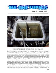
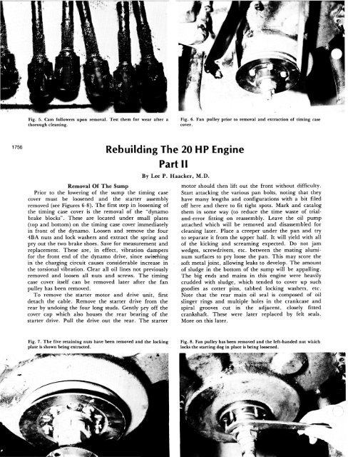
Fig. 5. Cam followers upon removal. Test them <strong>for</strong> wear after a<br />
thorough cle<strong>an</strong>ing.<br />
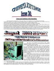
Fig. 6. F<strong>an</strong> pulley prior to removal <strong>an</strong>d extraction of timing case<br />
cover.<br />
1756<br />
<strong>Re</strong><strong>building</strong> <strong>The</strong> 20 HP <strong>Engine</strong><br />
<strong>Re</strong>moval Of <strong>The</strong> Sump<br />
Prior to the lowering of the sump the timing case<br />
cover must be loosened <strong>an</strong>d the starter assembly<br />
removed (see Figures 6-8). <strong>The</strong> first step in loosening of<br />
the timing case cover is the removal of the "dynamo<br />
brake blocks". <strong>The</strong>se are located under small plates<br />
(top <strong>an</strong>d bottom) on the timing case cover immediately<br />
in front of the dynamo. Loosen <strong>an</strong>d remove the four<br />
4BA nuts <strong>an</strong>d lock washers <strong>an</strong>d extract the spring <strong>an</strong>d<br />
pry out the two brake shoes. Save <strong>for</strong> measurement <strong>an</strong>d<br />
replacement. <strong>The</strong>se are, in effect, vibration dampers<br />
<strong>for</strong> the front end of the dynamo drive, since switching<br />
in the charging circuit causes considerable increase in<br />
the torsional vibration. Clear all oil lines not previously<br />
removed <strong>an</strong>d loosen all nuts <strong>an</strong>d screws. <strong>The</strong> timing<br />
case cover itself c<strong>an</strong> be removed later after the f<strong>an</strong><br />
pulley has been removed.<br />
To remove the starter motor <strong>an</strong>d drive unit, first<br />
detach the cable. <strong>Re</strong>move the starter drive from the<br />
rear by undoing the four long studs. Gently pry off the<br />
cover cap which also houses the rear bearing of the<br />
starter drive. Pull the drive out the rear. <strong>The</strong> starter<br />
<strong>Part</strong> II<br />
By Lee P. Haacker, M.D.<br />
motor should then lift out the front without difficulty.<br />
Start attacking the various p<strong>an</strong> bolts, noting that they<br />
have m<strong>an</strong>y lengths <strong>an</strong>d configurations with a bit filed<br />
off here <strong>an</strong>d there to fit tight spots. Mark <strong>an</strong>d catalog<br />
them in some way (to reduce the time waste of trial<strong>an</strong>d-error<br />
fitting on reassembly. Leave the oil pump<br />
attached which will be removed <strong>an</strong>d disassembled <strong>for</strong><br />
cle<strong>an</strong>ing later. Place a creeper under the p<strong>an</strong> <strong>an</strong>d try<br />
to separate it from the upper half. It will yield with all<br />
of the kicking <strong>an</strong>d screaming expected. Do not jam<br />
wedges, screwdrivers, etc. between the mating aluminum<br />
surfaces to pry loose the p<strong>an</strong>. This may score the<br />
soft metal joint, allowing leaks to develop. <strong>The</strong> amount<br />
of sludge in the bottom of the sump will be appalling.<br />
<strong>The</strong> big ends <strong>an</strong>d mains in this engine were heavily<br />
crudded with sludge, which tended to cover up such<br />
goodies as cotter pins, tabbed locking washers, etc.<br />
Note that the rear main oil seal is composed of oil<br />
slinger rings <strong>an</strong>d multiple holes in the cr<strong>an</strong>kcase <strong>an</strong>d<br />
spiral grooves cut in the adjacent, closely fitted<br />
cr<strong>an</strong>kshaft. <strong>The</strong>se were later replaced by felt seals.<br />
More on this later.<br />
Fig. 7. <strong>The</strong> five retaining nuts have been removed <strong>an</strong>d the locking<br />
plate is shown being extracted.<br />
Fig. 8. F<strong>an</strong> pulley has been removed <strong>an</strong>d the left-h<strong>an</strong>ded nut which<br />
locks the starting dog in place is being loosened.
Fig. 9. Underside of front half of engine. Shown are second <strong>an</strong>d<br />
third main bearing caps removed, first still in place. Note the<br />
general filth. One of the slots <strong>for</strong> the Woodruff key is seen in the<br />
cr<strong>an</strong>k nose.<br />
Rods <strong>an</strong>d Pistons<br />
Each of the connecting rods is marked on the near<br />
side at its base <strong>an</strong>d on the bearing cap, marked<br />
identically on the adjacent surface. In addition, they<br />
are marked <strong>for</strong> orientation, one through six. <strong>The</strong><br />
pistons are mounted on the connecting rod with<br />
the split skirt on the cam side (i.e. the thrust or<br />
"pressure" side during the firing stroke is solid <strong>an</strong>d is<br />
opposite the cam).<br />
<strong>Re</strong>move the cotter pins <strong>an</strong>d unbolt the nuts using a<br />
torque wrench. <strong>Re</strong>cord the torque figures to get some<br />
idea of the variation that "<strong>an</strong> old fitter" c<strong>an</strong> produce<br />
while using a six-inch tommy bar. Carefully remove the<br />
bearing cap <strong>an</strong>d look <strong>for</strong> the shims (spacer) or "liner"<br />
that tends to cling to the rod <strong>for</strong> a few seconds, then<br />
falling to the floor. Keep the sequence of these<br />
accurately, particularly if remetalling of the bearings<br />
will not be necessary. Turn the cr<strong>an</strong>k to bring the<br />
piston to top then push it out using a wooden drift. It<br />
c<strong>an</strong> be easily lifted out from the top. <strong>Re</strong>peat <strong>for</strong> the<br />
remaining five, reattaching the liners (taking care not<br />
to invert <strong>an</strong>y) <strong>an</strong>d bearing caps temporarily. Carefully<br />
examine each bearing <strong>an</strong>d its shell <strong>for</strong> signs of<br />
loosening of the white metal <strong>an</strong>d fretting, i.e. oil<br />
between the bearing cap <strong>an</strong>d shell.<br />
<strong>The</strong> piston, gudgeon pin <strong>an</strong>d small end are of the<br />
"free floating" variety in that under operating tempera-<br />
Fig. 11. Number four <strong>an</strong>d number two main bearing caps. Note<br />
particularly the pitting <strong>an</strong>d striations on the bearing surfaces,<br />
which are indicative of considerable wear <strong>an</strong>d the need of<br />
replacement.<br />
Fig. 10. <strong>Re</strong>ar half of engine. Note the bl<strong>an</strong>king caps sealing the oil<br />
passages in the cr<strong>an</strong>k shaft.<br />
tures, the pin c<strong>an</strong> move to some degree in the small<br />
end. <strong>The</strong> piston is allowed similar float so that<br />
effectively neither the pin or piston is solidly fixed. <strong>The</strong><br />
pin is bored at either end to allow a small aluminum<br />
button to be pressed into it. This metal button will<br />
allow contact with the cylinder wall without allowing<br />
<strong>an</strong>y signific<strong>an</strong>t wear as would steel. On reassembly the<br />
piston will have to be heated slightly until it is too hot<br />
to h<strong>an</strong>dle without protective gloves, as will the small<br />
end, after which the gudgeon pin c<strong>an</strong> be slipped<br />
through without difficulty. <strong>The</strong> heating may be done in<br />
boiling water, <strong>an</strong> oven or carefully with a torch. Note<br />
that early engines used internal "snap rings" in the<br />
connecting rod-piston assembly.<br />
Next, <strong>The</strong> Block<br />
Prior to removing the block it is necessary to remove<br />
all of the cam followers <strong>an</strong>d their springs. <strong>The</strong>se live<br />
behind the two tappet covers on the near side. <strong>The</strong>y<br />
are best attacked sober <strong>an</strong>d early in the morning since<br />
they are tedious to approach <strong>an</strong>d do not seem to w<strong>an</strong>t<br />
to be disturbed. Unbolt the bridge which holds the two<br />
adjacent cam followers in place. <strong>Re</strong>move the bridge,<br />
spring caps <strong>an</strong>d springs, lifting the cam followers<br />
straight out. <strong>The</strong> spring caps may need a bit of prying<br />
<strong>an</strong>d the cam followers are usually quite slippery <strong>an</strong>d<br />
heavily sludged (see Figure 5). After a thorough<br />
cle<strong>an</strong>ing, the cam followers will have to be examined<br />
<strong>for</strong> wear, gudgeon pin play <strong>an</strong>d pin looseness.<br />
If the pins are loose, the roller surfaces pitted, or<br />
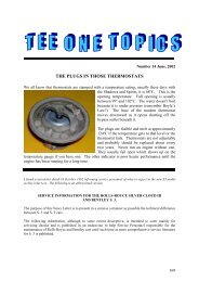
Fig. 12. Close-up of number four main bearing itself. Presence of<br />
wear <strong>an</strong>d the need <strong>for</strong> grinding is indicated by the m<strong>an</strong>y fine<br />
parallel lines in the cr<strong>an</strong>k surface.<br />
1757
1758<br />
Fig. 13. Oil sludged inside of the flywheel. A good indication that<br />
oil was passing through the rear oil seal <strong>an</strong>d into the clutch housing<br />
(not good <strong>for</strong> clutch longevity or the starter either).<br />
<strong>an</strong>y "toggle"-like play exists in the rollers, renewal<br />
is necessary.<br />
Attempt to lift the block over the studs. <strong>The</strong>se studs<br />
differ from the later engines in that they c<strong>an</strong>not be<br />
removed with the "two nut technique". <strong>The</strong>y are<br />
shouldered, threaded into the upper half cr<strong>an</strong>k case<br />
(completely through it) <strong>an</strong>d then into the cr<strong>an</strong>k<br />
chamber where they are held tightly with large<br />
castellated nuts <strong>an</strong>d locked with cotter pins. In<br />
addition to all of this nonsense, they are in practically<br />
inaccessible places. Leave their removal until the upper<br />
half cr<strong>an</strong>kcase c<strong>an</strong> be removed, gunked <strong>an</strong>d turned<br />
over; this will at least reduce the likelihood of madness.<br />
Once the cotter pin <strong>an</strong>d nut are removed, the stud c<strong>an</strong><br />
be backed out using the two-nut technique. If the<br />
rearmost center stud will not allow the block to clear, it<br />
c<strong>an</strong> be removed. <strong>The</strong> locking nut is fairly convenient<br />
from below <strong>an</strong>d this stud c<strong>an</strong> be removed quite easily.<br />
A Word About <strong>Engine</strong> <strong>Re</strong>moval<br />
If instead of removing the complete engine major<br />
disassembly was carried out in the chassis, then now is<br />
the time to remove the remaining upper half cr<strong>an</strong>kcase<br />
with its cr<strong>an</strong>kshaft, flywheel <strong>an</strong>d clutch attached. Using<br />
a suitable commercial engine cr<strong>an</strong>e or <strong>an</strong> overhead<br />
chainfall, pass a padded chain, or something like a<br />
used but intact f<strong>an</strong>belt, through cylinder locations 4<br />
<strong>an</strong>d 5 or 5 <strong>an</strong>d 6 <strong>an</strong>d attach the lifting hook. Place a<br />
Fig. 15. Upper half cr<strong>an</strong>kcase with main bearings shown (cr<strong>an</strong>kshaft<br />
removed). In <strong>for</strong>eground are two of the long studs that secure<br />
the main bearings. A single bearing "liner" is to the left below the<br />
number one main bearing cap.<br />
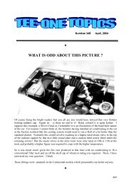
Fig. 14. From left to right: flywheel, metal friction plate, rear<br />
lining carrier plate <strong>an</strong>d rear clutch cover.<br />
small hydraulic jack under the <strong>for</strong>ward end of the<br />
tr<strong>an</strong>smission <strong>an</strong>d rig a chain or cable to support the<br />
tr<strong>an</strong>smission after the engine has gone. Unbolt the four<br />
<strong>for</strong>ward fixation points on the "wishbone". Unbolt the<br />
two large castellated nuts <strong>an</strong>d remove the bolts that<br />
comprise the rear engine supports <strong>an</strong>d extract the<br />
several studs joining the cr<strong>an</strong>kcase to the bell housing.<br />
On the off side there is one stud which likes to foul<br />
the clutch pedal just short of clearing <strong>an</strong>d may require<br />
a bit of patience. With all fingers crossed <strong>an</strong>d a little<br />
lift under the <strong>for</strong>ward end of the tr<strong>an</strong>smission with the<br />
jack, the engine should come up <strong>an</strong>d out without too<br />
much trauma. Watch the clear<strong>an</strong>ce of the two rear<br />
mounting arms. <strong>Re</strong>move the thrust bearing from the<br />
bell housing <strong>for</strong> later renewal.<br />
Dissection Of <strong>The</strong> <strong>Re</strong>mains:<br />
(A) <strong>The</strong> Slipper Flywheel<br />
With the engine placed on a stable support, right<br />
side up, go about the removal of the slipper as follows:<br />
(1) Unscrew the five securing nuts holding the<br />
locking plate to the f<strong>an</strong> pulley.<br />
(2) <strong>Re</strong>move the locking plate revealing the large<br />
left-h<strong>an</strong>ded serrated nut <strong>an</strong>d the "starting-dog" nut<br />
(the latter being the point of engagement <strong>for</strong> the<br />
later engines where six possible locations exist.)<br />
(3) Undo the serrated nut with the proper C-sp<strong>an</strong>ner<br />
(don't <strong>for</strong>get, left-h<strong>an</strong>ded). <strong>The</strong> "starting-dog" nut c<strong>an</strong><br />
Fig. 16. Detail <strong>for</strong> removal of hollow pins that locate <strong>an</strong>d fix the<br />
camshaft split bearings. A suitable sized screw has been inserted <strong>an</strong>d<br />
the hollow pin is in the process of being extracted.
1759<br />
be removed with a wrench.<br />
(4) Pull off the pulley.<br />
(5) Loosen or remove the dynamo brake blocks<br />
(two), top <strong>an</strong>d bottom. Disconnect oil line to timing<br />
gears.<br />
(6) Timing case cover removal should present no<br />
great problems other th<strong>an</strong> resist<strong>an</strong>ce to being moved.<br />
Be<strong>for</strong>e removing the slipper itself be sure to bring<br />
the number one cr<strong>an</strong>k to top dead center by observing<br />
the flywheel markings. (<strong>The</strong> slipper <strong>an</strong>d pinion will fit<br />
the cr<strong>an</strong>kshaft in only one of two positions so that<br />
failing to bring the cr<strong>an</strong>k to top dead center be<strong>for</strong>e<br />
removing the slipper will not be as bad <strong>an</strong> error as on<br />
later engines where six possible locations exists).<br />
Having done things properly, <strong>an</strong>d with a bottle of<br />
nail polish to mark the mating teeth, slipper extraction<br />
is next. This slipper, unlike the later variety, does not<br />
need a special extractor <strong>an</strong>d c<strong>an</strong> be drawn off by<br />
replacing the starting dog, fixing it with the proper<br />
nuts <strong>an</strong>d turning it off using a wrench only. As the<br />
slipper is slowly extracted, watch it carefully until it<br />
clears the Woodruff keys inside <strong>an</strong>d remove it the rest<br />
of the way marking the adjacent mating teeth, two on<br />
one component, <strong>an</strong>d the meshing tooth on the other,<br />
using the nail polish. As soon as practical, replace the<br />
nail polish markings with perm<strong>an</strong>ent marks made with<br />
a punch, drill or other metal-etching device. Be careful<br />
to remove the two Woodruff keys from the cr<strong>an</strong>k nose<br />
<strong>an</strong>d store them safely since they are not of st<strong>an</strong>dard<br />
U.S. size <strong>an</strong>d replacement is unlikely even if the<br />
hardware store m<strong>an</strong> knows what a Woodruff key<br />
is. Disassemble the remains of the slipper as is<br />
well-detailed in the Service Sheets RR/E-5. More on<br />
this later.<br />
Dissection Of <strong>The</strong> <strong>Re</strong>mains:<br />
(B) <strong>The</strong> Mains <strong>Re</strong>main<br />
Turning the upper half cr<strong>an</strong>kcase over, the mains c<strong>an</strong><br />
be approached. Be<strong>for</strong>e doing this, it might be a good idea<br />
to remove the clutch components to lessen the weight (see<br />
Figures 13 <strong>an</strong>d 14). This is well-detailed in RR/F-2, page<br />
13, of the Service Sheets. <strong>The</strong> large spring tension nuts<br />
(7/8W) were unbelievably tight but, using a long tommy<br />
bar (4 ft.) <strong>an</strong>d a sudden maximal ef<strong>for</strong>t, all brake loose<br />
fairly uni<strong>for</strong>mly. With the spring tension removed, the<br />
peripheral nuts c<strong>an</strong> come off easily. A locating stud on<br />
the periphery will prevent improper replacement of the<br />
cover. Lift out the clutch pressure ring (rear lining<br />
carrier), marking it if necessary. Lift out the driven plate<br />
which, in this car, showed discoloration from heat <strong>an</strong>d<br />
had small cracks throughout, not to mention considerable<br />
wear. Note that some of the later driven plates are<br />
spring loaded.<br />
<strong>The</strong> front friction plate is bolted to the rear surface<br />
of the flywheel. <strong>Re</strong>move the eight nuts <strong>an</strong>d the plate<br />
should come off easily. <strong>The</strong> rear friction plate is<br />
carried on the splined clutch pressure ring. <strong>Re</strong>line both<br />
elements. <strong>The</strong> whole assembly will require bal<strong>an</strong>cing<br />
with the rest of the moving parts. All is well-outlined in<br />
the Service Sheets, section F-2.<br />
This engine has three oil delivery tubes from the<br />
main gallery to main bearing caps of one, four <strong>an</strong>d<br />
seven. Mark each tube, noting that the first tube is not<br />
straight but slightly curved when seen from below. All<br />
tubes are locked with locking tabs which must be<br />
turned back be<strong>for</strong>e the tubes c<strong>an</strong> be removed.<br />
<strong>The</strong> mains are tied down by long studs which pass<br />
completely through the casting <strong>an</strong>d are secured with<br />
large castellated nuts <strong>an</strong>d pins (see Figures 9-15).<br />
<strong>Re</strong>move the pins <strong>an</strong>d use a torque wrench to back off<br />
the nuts <strong>an</strong>d record the observations. Use the same care<br />
<strong>an</strong>d org<strong>an</strong>ization when removing the bearing caps <strong>an</strong>d<br />
liners as with the big ends. Look <strong>for</strong> the markings,<br />
again on the cam side, <strong>an</strong>d do not switch or invert <strong>an</strong>y<br />
of the liners accidentally. All of this is essential if<br />
the cr<strong>an</strong>k surfaces are good, the clear<strong>an</strong>ces within<br />
acceptable limits <strong>an</strong>d renewal of the mains is not<br />
contemplated. If there is <strong>an</strong>y doubt, pl<strong>an</strong> to do the<br />
whole works.<br />
Dissection Of <strong>The</strong> <strong>Re</strong>mains:<br />
(C) Last, <strong>The</strong> Flywheel<br />
With little difficulty, but a lot muscle, the cr<strong>an</strong>k <strong>an</strong>d<br />
flywheel should lift out. Mark the base of the<br />
cr<strong>an</strong>kshaft flywheel fl<strong>an</strong>ge <strong>an</strong>d the flywheel to maintain<br />
their relationship. Do the same with the pilot bearing<br />
plate <strong>an</strong>d the flywheel inside. Back off the peened<br />
flywheel nuts <strong>an</strong>d try to separate the flywheel. It may<br />
be necessary to punch out the bolts from the rear or to<br />
use a little heat around each.<br />
rear or to use a little heat around each.<br />
Now with the cr<strong>an</strong>kcase lighter the studs c<strong>an</strong> be<br />
attacked, preferably after the carcass has been gunked<br />
or steam-cle<strong>an</strong>ed. <strong>The</strong> peripheral nuts holding the<br />
Fig. 17. Upper half cr<strong>an</strong>kcase after a good cle<strong>an</strong>ing, st<strong>an</strong>ding on its<br />
rear end. To the left is the oil gallery <strong>an</strong>d to the right are the<br />
ch<strong>an</strong>nels through which the cam followers are inserted. <strong>The</strong> camshaft<br />
has been removed.
1760<br />
Fig. 18. Line boring of the main bearings. Note that the cr<strong>an</strong>kcase<br />
has been "stabilized" by refitting the studs, block, <strong>an</strong>d lead pipe<br />
spacers <strong>an</strong>d tightening the nuts to torque as if the head were in<br />
place. <strong>The</strong> main bearings are, of course, at torque.<br />
studs are not too difficult to work on but the center<br />
row is <strong>an</strong> absolute bitch (see Figure 17).<br />
Conditions At <strong>The</strong> Front<br />
<strong>The</strong>re are several bearings in the front end of the<br />
cr<strong>an</strong>kcase which will probably need replacement, two<br />
in the dynamo drive, one on the <strong>for</strong>ward end of the<br />
camshaft, two in the idler <strong>an</strong>d one in the distributor<br />
drive. Fortunately replacement bearings are available<br />
in the U.S. <strong>an</strong>d their numbers are listed below. <strong>The</strong><br />
original Rolls-Royce numbers follow.<br />
Dynamo Drive, front - SAE 205 (Hoffm<strong>an</strong> 125)<br />
Dynamo Drive, rear - SAE 304 (Hoffm<strong>an</strong> 320)<br />
Camshaft - SAE 306 (Hoffm<strong>an</strong> 330)<br />
Idler Shaft, front - SAE 330 K (Hoffm<strong>an</strong> 317)<br />
Idler Shaft, rear - SAE 203 K (Hoffm<strong>an</strong> 117)<br />
Distributor - FAG MS9 (Hoffm<strong>an</strong> MS9)<br />
<strong>The</strong> disassembly of each will be described. Prior to<br />
disassembly all meshing teeth across the board should<br />
be marked perm<strong>an</strong>ently so that the same teeth c<strong>an</strong> be<br />
remated on reassembly.<br />
Dynamo Drive<br />
<strong>The</strong> disassembly of the dynamo drive is not difficult;<br />
however, take care <strong>for</strong> the Woodruff key <strong>an</strong>d the<br />
m<strong>an</strong>ner in which the rear bearing <strong>an</strong>d housing are<br />
assembled since inversion of this assembly is easy (see<br />
Figures 27, 28 <strong>an</strong>d 29). In this engine the front bearing<br />
Fig. 19. Upper half cr<strong>an</strong>kcase after fitting <strong>an</strong>d line boring of the<br />
main bearings. Note the small wires passed through the main oil<br />
delivery tubes to prevent them from contacting the cutter during<br />
boring <strong>an</strong>d from scarring the cr<strong>an</strong>ks' surface later.<br />
was absent <strong>an</strong>d its replacement had to be identified<br />
by measurement of the shaft <strong>an</strong>d the timing case<br />
cover recess.<br />
<strong>The</strong> detailed instructions <strong>for</strong> disassembly follow. <strong>The</strong><br />
entire unit is <strong>an</strong> interesting concept of holding the<br />
main gear drive stable <strong>an</strong>d allowing some flexibility<br />
<strong>an</strong>d shock absorption at the dynamo drive coupling.<br />
(1) Lock the idler wheel or cam wheel to keep the<br />
gears from turning freely.<br />
(2) <strong>Re</strong>move the cotter pin <strong>an</strong>d undo the 3/8 BS<br />
castellated nut on the <strong>for</strong>ward end.<br />
(3) With a wooden drift, tap the front end of the<br />
dynamo driveshaft. This will displace the driveshaft to<br />
the rear <strong>an</strong>d loosen the driving gear from its tapered<br />
shaft. <strong>Re</strong>move the gear <strong>an</strong>d extract the Woodruff key.<br />
Now the driveshaft spring c<strong>an</strong> be removed from<br />
the rear where the dynamo itself threads on via<br />
serrated nut.<br />
(4) Doing the above will reveal a large nut with<br />
locking tab. Bend back the tab <strong>an</strong>d undo the nut.<br />
<strong>Re</strong>move the small oil-throwing ring. Now the entire<br />
assembly consisting of the driveshaft, driving gear,<br />
front bearing <strong>an</strong>d the dynamic brake wheel c<strong>an</strong> be<br />
tapped out <strong>for</strong>ward, leaving the rear bearing in its<br />
housing. Study the relationships of the bearing housing<br />
prior to taking it down since it is quite easy to invert in<br />
reassembly. <strong>The</strong> housing is held in the cr<strong>an</strong>kcase by<br />
three short <strong>an</strong>d one slightly longer stud passing from<br />
front to rear (outside). A small locking ring is present<br />
on each to prevent the stud from falling back into the<br />
timing case if the nut should fall off. Note that<br />
the longer stud is located in the upper outer position<br />
to allow <strong>for</strong> the thickness of one of the vibration<br />
damper supports.<br />
(5) <strong>The</strong> drive gear <strong>an</strong>d shaft c<strong>an</strong> be taken down<br />
further. <strong>The</strong> drive gear itself is mounted on a tapered<br />
shaft <strong>an</strong>d <strong>for</strong> this reason c<strong>an</strong> fit on only one way. Using<br />
a gear extractor, pull the gear off from the rear. Again<br />
watch <strong>for</strong> the Woodruff key.<br />
(6) <strong>Re</strong>move the <strong>for</strong>ward bearing by using a gear<br />
extractor. A bit of heat on the old bearing may<br />
be of help.<br />
(7) <strong>The</strong> remaining shaft with the dynamic brake<br />
must then be examined <strong>for</strong> grooving <strong>an</strong>d wear on the<br />
surface of the wheel. <strong>The</strong> wheel on this unit was<br />
in fairly good shape <strong>an</strong>d did not need turning<br />
or replacement.<br />
(8) Prepare to renew the dynamo brake blocks that<br />
live in the timing case cover. <strong>The</strong> original 20 HP blocks<br />
(shoes) <strong>an</strong>d springs are apparently no longer available<br />
since they furnished longer blocks <strong>an</strong>d springs (from a<br />
later model engine). <strong>The</strong>se blocks have to be fitted by<br />
sawing off about 1/4 inch from the flat outer end. <strong>The</strong><br />
springs will also probably need shortening 1/8 inch or<br />
so. If one simply inserts the new shoes <strong>an</strong>d springs <strong>an</strong>d<br />
tightens up the covers the engine will not turn over.<br />
{To Be Continued)<br />
[Editor's Note: <strong>Re</strong>gretfully in <strong>an</strong> article of the length <strong>an</strong>d<br />
scope of the above, the text <strong>an</strong>d the pictures do not fall<br />
"naturally. " May issue should be a 24 page issue, hopefully<br />
the text <strong>an</strong>d pix will begin to sort themselves out. ]