Pioneer Pipe - Russel Metals, Inc.
Pioneer Pipe - Russel Metals, Inc.
Pioneer Pipe - Russel Metals, Inc.

You also want an ePaper? Increase the reach of your titles
YUMPU automatically turns print PDFs into web optimized ePapers that Google loves.
1.800.525.1266<br />
5th Edition 11
5th Edition<br />
October 2011<br />
Our Customers Come First<br />
<strong>Pioneer</strong> <strong>Pipe</strong> was founded in Denver, Colorado in 1974, and has become<br />
one of the leading distributors of standard and line pipe in the United<br />
States. <strong>Pioneer</strong>’s foundation is built on an extensive inventory of quality<br />
products, competitive pricing, excellent service, and friendly, experienced<br />
salespeople. Bringing these elements into unified focus helps to meet or<br />
exceed the expectations of customers in nearly every state and in several<br />
foreign counties.<br />
We sincerely believe the most important reason for our continued<br />
success is that our customers are our number one priority. We continue<br />
to serve our well-established customer base, in addition to building new<br />
customer relationships, by making it easy to do business with <strong>Pioneer</strong> at<br />
every point of contact. Whether you need line pipe or standard pipe in<br />
various grades, sizes, coatings, and end finishes; we will customize any<br />
order to meet your needs.<br />
<strong>Pioneer</strong> has proven ability to handle massive projects or small orders.<br />
Our pipe products have helped to build numerous oil & natural gas<br />
pipelines both domestic and international, international airports, the<br />
Luge Run for the 2002 Olympics, convention centers, snow-making<br />
pipelines, fiber-optic lines, and stadiums. We also provide pipe for<br />
plumbing in schools, churches, and community centers.<br />
In order to position the company for continued success and profitable<br />
growth, <strong>Pioneer</strong> became part of <strong>Russel</strong> <strong>Metals</strong>, <strong>Inc</strong>. in July of 1994.<br />
Based in Toronto, Canada, <strong>Russel</strong> <strong>Metals</strong> is one of the largest steel<br />
Service Center Operations in North America, with sales exceeding<br />
$3.4 billion. Joining <strong>Russel</strong> <strong>Metals</strong> enabled <strong>Pioneer</strong> to combine over 38<br />
years of excellence in pipe manufacturing and distribution with <strong>Russel</strong><br />
<strong>Metals</strong>’ heritage as a leader since 1784 in the North American <strong>Metals</strong><br />
Industry.<br />
www.pioneerpipe.com<br />
sales@pioneerpipe.com<br />
Phone: 303 289-3201<br />
Toll Free: 800 525-1266<br />
Fax: 303 289-6381<br />
1660 Lincoln, Suite 1950, Denver, C0 80264
Table of Contents<br />
Standards & Specifications .....................................................................2<br />
Submittal Data<br />
A53 Type F Grade A.......................................................................3<br />
A53 Type E Grade B.......................................................................4<br />
API 5L 44th Edition................................................................... 5-17<br />
A106 Type S Grade B...................................................................18<br />
A500..........................................................................................19<br />
A252 Piling <strong>Pipe</strong> ..........................................................................20<br />
Reject, Structural, Limited Service .................................................21<br />
Standard <strong>Pipe</strong> And Pressure Tubing Data ...............................................22<br />
Standard <strong>Pipe</strong> And Line <strong>Pipe</strong> Data .................................................... 23-40<br />
Charts, Formulas, Calculations & Conversions................................... 41-48<br />
External <strong>Pipe</strong> Coatings<br />
Types, Weights, & Calculations ..................................................... 49-52<br />
Galvanizing, Grooving, Threading, Zap-Lok.......................................... 53-58<br />
Glossary Of Terms.......................................................................... 59-61<br />
Legal Notice: This brochure is intended for general information only. <strong>Pioneer</strong> makes no warranty or representation, expressed or implied, of any kind with respect to the information<br />
contained herein and shall in no event assume liability or responsibility for any loss, damage or injury whatsoever resulting from the use of this information. In all cases, the customer<br />
is therefore requested to use this information at its own risk and responsibility.<br />
1
SUBMITTAL DATA<br />
Standards & Specifications<br />
ASTM A 120-84 Standard Specification for<br />
<strong>Pipe</strong>, Steel, Black and Hot Dipped Zinc-<br />
Coated (Galvanized) Welded and Seamless,<br />
for Ordinary Uses<br />
This specification covers black and hot-dipped galvanized welded and<br />
seamless steel pipe in NPS 1 /8" to NPS 16" inclusive. Formerly under<br />
the jurisdiction of ASTM Committee A-1 on Steel, Stainless Steel, and<br />
Related Alloys, this specification was discontinued in 1988 and<br />
replaced by Specification A 53, for <strong>Pipe</strong>, Steel, Black and Hot-<br />
Dipped, Zinc-Coated Welded and Seamless.<br />
AWWA Standard for Steel <strong>Pipe</strong> Six <strong>Inc</strong>hes<br />
and Larger<br />
By reference, the former AWWA C202 included API 5L and 5LX pipe<br />
grades manufactured to the American Petroleum Institute (API)<br />
standards for high pressure applications. With the advent of ASTM<br />
A570 and A572 high strength steels being included in AWWA C200,<br />
API high pressure pipe was omitted from AWWA C200 as being redundant.<br />
However, API 5L and 5LX pipe grades fully meet all requirements<br />
of AWWA C200 and can be used for water works applications if<br />
dictated by availability or other economic considerations.<br />
American National Standards Institute<br />
(ANSI)<br />
ANSI B2.1 Basic standard for steel pipe threads<br />
ANSI B36.10 Basic dimensional standard for all steel pipe<br />
ANSI B31 Code for design and construction of pressure piping<br />
systems, consisting of the following sections:<br />
ANSI B31.1 Power Piping Systems<br />
ANSI B31.2 Industrial Gas and Air Piping Systems<br />
ANSI B31.3 Petroleum Refinery Piping<br />
ANSI B31.4 Liquid Petroleum Transportation Piping<br />
ANSI B31.5 Refrigeration Piping Systems<br />
ANSI B31.6 Chemical Process Piping<br />
ANSI B31.7 Nuclear Power Piping<br />
ANSI B31.8 Gas Transmission and Distribution Piping<br />
American Petroleum Institute (API)<br />
API 5L Specification for Line <strong>Pipe</strong><br />
API 5LX Specification for High-Test Line <strong>Pipe</strong><br />
PSL<br />
Specification for High-Test Line <strong>Pipe</strong><br />
American Society for Testing and Materials<br />
(ASTM)<br />
ASTM A53 Welded and Seamless Steel <strong>Pipe</strong><br />
ASTM A106 Seamless Carbon Steel <strong>Pipe</strong> for High<br />
Temperature Service<br />
ASTM A135 Electric-Resistance-Welded <strong>Pipe</strong>, 30 inch and<br />
under, intended for conveying liquid, gas, or vapor<br />
ASTM A252 Welded and Seamless Steel <strong>Pipe</strong> Piles<br />
ASTM A333 Seamless and Welded Steel <strong>Pipe</strong> for Low<br />
Temperature Service<br />
American Water Works Association (AWWA)<br />
AWWA C200 AWWA Standard and Welded Carbon Steel Water<br />
Well <strong>Pipe</strong><br />
2<br />
Legal Notice: This brochure is intended for general information only. <strong>Pioneer</strong> makes no warranty or representation, expressed or implied, of any kind with respect to the information<br />
contained herein and shall in no event assume liability or responsibility for any loss, damage or injury whatsoever resulting from the use of this information. In all cases, the customer is<br />
therefore requested to use this information at its own risk and responsibility.
SUBMITTAL DATA<br />
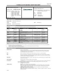
ASTM A53 Type F Grade A <strong>Pipe</strong><br />
Scope<br />
Covers black and hot-dipped galvanized furnace butt-welded<br />
(continuous welded) Grade A pipe. 1/8"-4" <strong>Pipe</strong> is intended<br />
for mechanical and pressure applications and is acceptable<br />
for ordinary uses in steam, water, gas and air lines. <strong>Pipe</strong><br />
is suitable for welding, threading, grooving and bending.<br />
Hot-Dipped Galvanized<br />
The average weight of zinc coating shall be not less than<br />
1.8 oz. per sq. ft. of surface (inside and outside).<br />
When galvanized pipe is bent or otherwise fabricated<br />
to a degree which causes zinc coating to stretch or compress<br />
beyond the limit of elasticity, some flaking of the coating<br />
may occur.<br />
Hydrostatic Testing<br />
Hydrostatic test pressures for plain-end pipe are<br />
indicated below.<br />
NPS Std. Weight Extra Strong<br />
1<br />
⁄8" through 1" 700 psi 850 psi<br />
1 ⁄4" through 3" 1000 psi 1300 psi<br />
3 1 ⁄2" through 4" 1200 psi 1700 psi<br />
Chemical Requirements<br />
Composition, max. %<br />
Carbon Manganese Phosphorus Sulfur<br />
.30 1.20 .05 .045<br />
*Copper *Nickel *Chromium *Molybdenum *Vanadium<br />
.40 .40 .40 .15 .08<br />
*The combination of these five elements<br />
shall not exceed 1.00%.<br />
Tensile Requirements<br />
Tensile Strength, min. 48,000 psi<br />
Yield Strength, min.<br />
30,000 psi<br />
Flattening Test<br />
As a test for quality of the weld for pipe 2 1 ⁄2" NPS and larger,<br />
position the weld at 90˚ from the direction of force and flatten until the<br />
OD is 3 ⁄4 of the original outside diameter. No cracks shall occur along<br />
the inside or outside surface of the weld.<br />
Frequency of Tests<br />
Tensile tests are required on each lot of 25 tons or fraction thereof<br />
of pipe NPS 1 ⁄2" and smaller and from each lot of 50 tons or fraction<br />
thereof of pipe NPS 2 and larger.<br />
For NPS 2 1 ⁄2" and larger, a flattening test is also required on each lot of<br />
50 tons.<br />
Dimensions and Weights<br />
The dimensions and weights furnished under this specification are in<br />
agreement with the standardized dimensions and weights specified in<br />
ASME B 36.10.<br />
Permissible<br />
Variations<br />
in Wall<br />
Thickness<br />
Minimum wall thickness<br />
at any point shall<br />
not be more than<br />
12.5% under nominal<br />
wall thickness<br />
specified.<br />
Nominal<br />
Size<br />
1<br />
/8"<br />
1<br />
/4"<br />
3<br />
/8"<br />
1<br />
/2"<br />
3<br />
/4"<br />
1"<br />
1 /4"<br />
1 /2"<br />
2"<br />
2 1 /2"<br />
3"<br />
3 1 /2"<br />
4"<br />
OD<br />
<strong>Inc</strong>hes<br />
Black Plain End<br />
.405<br />
.540<br />
.675<br />
.840<br />
1.050<br />
1.315<br />
1.660<br />
1.900<br />
2.375<br />
2.875<br />
3.500<br />
4.000<br />
4.500<br />
Sch. 40 Sch. 80<br />
Weight<br />
Weight<br />
Wall Lb./Ft. Wall Lbs./Ft.<br />
.068<br />
.088<br />
.091<br />
.109<br />
.113<br />
.133<br />
.140<br />
.145<br />
.154<br />
.203<br />
.216<br />
.226<br />
.237<br />
.24<br />
.43<br />
.57<br />
.85<br />
1.13<br />
1.68<br />
2.27<br />
2.72<br />
3.66<br />
5.80<br />
7.58<br />
9.12<br />
10.80<br />
.095<br />
.119<br />
.126<br />
.147<br />
.154<br />
.179<br />
.191<br />
.200<br />
.218<br />
.276<br />
.300<br />
.318<br />
.337<br />
Permissible Variations in Outside Diameter<br />
NPS 1 /2" and under: ± 1/64”<br />
NPS 2" and over: ± 1%<br />
Permissible Variations Weight Per Foot<br />
<strong>Pipe</strong> shall not vary more than ± 10% from the standard specified.<br />
Product Marking<br />
Each length of pipe 1 /2" NPS and larger is continuously stenciled to<br />
show the manufacturer, the grade of pipe (ASTM A53), the kind of pipe<br />
(F for continuous weld, A for Grade A), the size, XS for extra strong,<br />
and length.<br />
.31<br />
.54<br />
.74<br />
1.09<br />
1.48<br />
2.17<br />
3.00<br />
3.63<br />
5.03<br />
7.67<br />
10.26<br />
12.52<br />
15.00<br />
Legal Notice: This brochure is intended for general information only. <strong>Pioneer</strong> makes no warranty or representation, expressed or implied, of any kind with respect to the information<br />
contained herein and shall in no event assume liability or responsibility for any loss, damage or injury whatsoever resulting from the use of this information. In all cases, the customer<br />
is therefore requested to use this information at its own risk and responsibility.<br />
3
SUBMITTAL DATA<br />
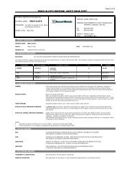
ASTM A53 Type E Grade B <strong>Pipe</strong><br />
Scope<br />
Covers black and hot-dipped galvanized electric-resistance welded<br />
Grade B pipe in NPS 2" - 26". <strong>Pipe</strong> is intended for mechanical and pressure<br />
applications and is acceptable for ordinary uses in steam, water,<br />
gas and air lines. <strong>Pipe</strong> is suitable for welding, threading, grooving.<br />
Manufacture<br />
The weld seam shall be heat treated after welding to a minimum of<br />
1000˚ F or be otherwise processed in such a manner that no untempered<br />
martensite remains.<br />
Hot-Dipped Galvanized<br />
The average weight of zinc coating shall be not less than 1.8 oz. per sq.<br />
ft. of surface (inside and outside).<br />
When galvanized pipe is bent or otherwise fabricated to a degree which<br />
causes zinc coating to stretch or compress beyond the limit of elasticity,<br />
some flaking of the coating may occur.<br />
Hydrostatic and Nondestructive Testing<br />
Hydrostatic inspection test pressures for plain-end pipe are listed in<br />
Table X2.2 of the A53 specification. Test pressures shall be maintained<br />
for a minimum of five seconds.<br />
Nondestructive testing of the weld seam is required on each length of<br />
ERW pipe NPS 2" and larger.<br />
Chemical Requirements<br />
Composition, max. %<br />
CarbonMaganesePhosphorusSulfer<br />
Manganese Phosphorus Sulfur<br />
.30 1.20 .05 .045<br />
*Copper *Nickel *Chromium *Molybdenum *Vanadium<br />
.40 .40 .40 .15 .08<br />
*The combination of these five elements<br />
shall not exceed 1.00%.<br />
Tensile Requirements<br />
Tensile Strength, min. 60,000 psi<br />
Yield Strength, min.<br />
35,000 psi<br />
Note: A transverse test is required on pipe NPS 8 and larger.<br />
Frequency of Tests<br />
Tensile tests are required on one length of pipe each lot of 500 lengths<br />
or fraction thereof for each size. Refer to A53 specification for frequency<br />
of flattening tests.<br />
Dimensions and Weights<br />
The dimensions and weights furnished under this specification are in<br />
agreement with the standardized dimensions and weights specified in<br />
ASME B 36.10.<br />
Permissible Variations in Wall Thickness<br />
Minimum wall<br />
thickness at any point Standard (Sch.40) Black Plain End<br />
shall not be more than<br />
12.5% under nominal Nominal OD Wall Weight<br />
wall thickness specified.<br />
Size <strong>Inc</strong>hes<br />
Lbs./Ft.<br />
2" 2.375 .154 3.66<br />
2 1 /2" 2.875 .203 5.80<br />
3" 3.500 .216 7.58<br />
3 1 /2" 4.000 .226 9.12<br />
4" 4.500 .237 10.80<br />
5" 5.563 .258 14.63<br />
6" 6.625 .280 18.99<br />
8" 8.625 .322 28.58<br />
Permissible<br />
Variations<br />
in Outside<br />
Diameter<br />
<strong>Pipe</strong> 2" NPS and<br />
larger shall not<br />
vary more than ± 1%<br />
from the standard<br />
specified.<br />
Nominal<br />
Size<br />
Extra Strong (Sch.80)<br />
Black Plain End<br />
OD<br />
<strong>Inc</strong>hes<br />
Wall<br />
2" 2.375 .218<br />
2 1 /2" 2.875 .276<br />
3" 3.500 .300<br />
3 1 /2" 4.000 .318<br />
4" 4.500 .337<br />
Permissible *For additional sizes and wall see pages 23-40.<br />
Variations in<br />
Weight per Foot<br />
<strong>Pipe</strong> shall not vary more than ± 10% from the standard specified.<br />
Weight<br />
Lbs./Ft.<br />
5.03<br />
7.67<br />
10.26<br />
12.52<br />
15.00<br />
Product Marking<br />
Each length of pipe is continuously stenciled to show the manufacturer,<br />
the grade of pipe (ASTM A53), the kind of pipe (E for electric-resistance<br />
welded, B for Grade B), the size, XS for extra strong, and length.<br />
Flattening Test<br />
As a test for quality of the weld for pipe 2" NPS and larger,<br />
position the weld at 0˚ to the direction of force and flatten until<br />
the OD is 2 ⁄3 of the original outside diameter. No cracks shall<br />
occur along the inside or outside surface of the weld.<br />
4<br />
Legal Notice: This brochure is intended for general information only. <strong>Pioneer</strong> makes no warranty or representation, expressed or implied, of any kind with respect to the information<br />
contained herein and shall in no event assume liability or responsibility for any loss, damage or injury whatsoever resulting from the use of this information. In all cases, the customer is<br />
therefore requested to use this information at its own risk and responsibility.
SUBMITTAL DATA<br />
API 5L API 5L Specifications 44th Edition<br />
Scope<br />
Covers WELDED and SEAMLESS pipe suitable for use in conveying<br />
gas, water, and oil in both the oil and natural gas industries.<br />
Product Specification Level<br />
This specification establishes requirements for two product specification<br />
levels (PSL 1 and PSL 2). These two PSL designations define different<br />
levels of standard technical requirements. PSL 2 has mandatory<br />
requirements for carbon equivalent, notch toughness, maximum yield<br />
strength, and maximum tensile strength. Requirements that apply to<br />
only PSL 1 or only PSL 2 are so designated. Requirements that are<br />
not designated to a specific PSL apply to both PSL 1 and PSL 2.<br />
Tensile Requirements<br />
Lists minimum yield and tensile strength for all grades as well as a<br />
maximum tensile strength for X80. Maximum yield-to-tensile ratios outlined<br />
for cold-expanded pipe may be waived when a fracture toughness<br />
requirement is specified.<br />
(See tables 6 & 7)h<br />
Mechanical Test Specified<br />
Tensile Test:<br />
Buttweld: All sizes- Longitudinal specimens<br />
Seamless and Electric Weld: Under 8 5 /8"- Longitudinal<br />
8 5 /8" and Larger - Transverse<br />
Grades and Dimensions<br />
PSL 1 can be supplied in grades A25 - X70 and sizes ranging<br />
from 1 /8" through 80".<br />
Bending Test: 9.5 API 44th Edition<br />
No cracks shall occur in any portion of the test piece and no opening of<br />
the weld shall occur. (See page 12)<br />
PSL 2 can be supplied in grades B - X80 and sizes ranging<br />
from 4½" through 80".<br />
Chemical Requirements<br />
(See tables 4 & 5)<br />
Hydrostatic Testing<br />
(See 9.4 on page 12)<br />
Test Pressures are held for not less than:<br />
Seamless (all sizes) — 5 seconds<br />
Welded (NPS 18" and smaller) — 5 seconds<br />
(NPS 20" and larger) — 10 seconds<br />
Flattening Test:<br />
Buttweld: NPS 2 1 /2" and larger.<br />
Electric-Weld: All sizes. (See page 12)<br />
Fracture Toughness Tests<br />
Charpy Impact tests<br />
PSL 1- Not required<br />
PSL 2-Required for pipe specified<br />
wall thicknesses in the table below<br />
(See Chart on page 11)<br />
Abbreviated Terms<br />
COWH<br />
COWL<br />
CTOD<br />
CVN<br />
CW<br />
DWT<br />
EDI<br />
EW<br />
HAZ<br />
HBW<br />
HFW<br />
HIC<br />
HRC<br />
combination helical welding process for pipe during<br />
manufacturing<br />
combination longitudinal welding process for pipe during<br />
manufacturing<br />
crack tip opening displacement<br />
Charpy V-notch<br />
continuous welding process for pipe during manufacturing<br />
drop-weight tear<br />
electronic data interchange<br />
electronic resistance or electric induction welding process for<br />
pipe during manufacturing<br />
heat-affected zone<br />
Brinell hardness<br />
high-frequency electric welding process for pipe during<br />
manufacturing<br />
hydrogen-induced cracking<br />
Rockwell hardness, C scale<br />
HV Vickers hardness<br />
IQI image quality indicator<br />
LFW low-frequency electric welding process for pipe during<br />
manufacturing<br />
LW laser welding process for pipe during manufacturing<br />
NDT non-destructive testing<br />
PSL product specification level<br />
SAWH submerged-arc helical welding process for pipe during<br />
manufacture<br />
SAWL submerged-arc longitudinal welding process for pipe during<br />
manufacture<br />
SSC sulfide stress cracking<br />
SWC step-wise cracking<br />
TFL through the flowline<br />
T2, T3 radiographic film classification<br />
USC United States customary<br />
Legal Notice: This brochure is intended for general information only. <strong>Pioneer</strong> makes no warranty or representation, expressed or implied, of any kind with respect to the information<br />
contained herein and shall in no event assume liability or responsibility for any loss, damage or injury whatsoever resulting from the use of this information. In all cases, the customer<br />
is therefore requested to use this information at its own risk and responsibility.<br />
5
SUBMITTAL DATA<br />
<strong>Pipe</strong> Grades, Steel Grades & Acceptable Delivery Conditions<br />
Table 1<br />
PSL Delivery Condition <strong>Pipe</strong> grade/steel<br />
grade a,b<br />
PSL 1 As-rolled, normalizing rolled, normalized or normalizing formed L175 or A25<br />
L175P or A25P<br />
L210 or A<br />
As-rolled, normalizing rolled, thermomechanical rolled, thermomechanical formed, normalizing formed, normalized, L245 or B<br />
normalized and tempered; or, if agreed, quenched and tempered for SMLS pipe only<br />
As-rolled, normalizing rolled, thermomechanical rolled, thermomechanical formed, normalizing formed, normalized, L290 or X42<br />
normalized and tempered or quenched and tempered<br />
L320 or X46<br />
L360 or X52<br />
L390 or X56<br />
L415 or X60<br />
L450 or X65<br />
L485 or X70<br />
PSL 2 As-Rolled L245R or BR<br />
delivery condition without any special rolling and/or heat-treatment<br />
L290R or X42R<br />
Normalizing rolled, normalizing formed, normalized or normalized and tempered<br />
L245N or BN<br />
Formed: pipe delivery condition resulting from the forming process in which the final deformation is carried out within a L290N or X42N<br />
certain temperature range, leading to a material condition equivalent to that obtained after normalizing, such that the<br />
L320N or X46N<br />
specified mechanical properties would still be met in the event of any subsequent normalizing.<br />
Rolled: pipe delivery condition resulting from the rolling process in which the final deformation is carried out within a certain<br />
L360N or X52N<br />
temperature range, leading to a material condition equivalent to that obtained after normalizing, such that the speci-<br />
fied mechanical properties would still be met in the event of any subsequent normalizing.<br />
L390N or X56N<br />
L415N or X60N<br />
Quenched and Tempered<br />
L245Q or BQ<br />
heat treatment consisting of quench hardening followed by tempering<br />
L290Q or X42Q<br />
L320Q or X46Q<br />
L360Q or X52Q<br />
L390Q or X56Q<br />
L415Q or X60Q<br />
L450Q or X65Q<br />
L485Q or X70Q<br />
L555Q or X80Q<br />
Thermomechanical Rolled or Thermomechanical Formed<br />
L245M or BM<br />
Rolled: pipe delivery condition resulting from the hot-rolling process for strip or plate, in which the final deformation is L290M or X42M<br />
carried out in a certain temperature range, leading to a material condition with certain properties that cannot be achieved<br />
L320M or X46M<br />
or repeated by heat treatment alone, and such deformation is followed by cooling, possibly with increased cooling rates,<br />
with or without tempering, self-tempering included<br />
L360M or X52M<br />
Formed: hot-forming process for pipe, in which the final deformation is carried out in a certain temperature range, leading<br />
to a material condition with certain properties that cannot be achieved or repeated by heat treatment alone, and such<br />
deformation is followed by cooling, possibly with increased cooling rates, with or without tempering, self-tempering<br />
included<br />
Thermomechanical Rolled<br />
L390M or X56M<br />
L415M or X60M<br />
L450M or X65M<br />
L485M or X70M<br />
L555M or X80M<br />
L625M or X90M<br />
L690M or X100M<br />
L830M or X120M<br />
a<br />
For intermediate grades, the steel grades shall be as agreed, but consistent with the above format.<br />
b<br />
The suffix (R, N, Q or M) for PSL 2 grades belongs to the steel grade.<br />
6<br />
Legal Notice: This brochure is intended for general information only. <strong>Pioneer</strong> makes no warranty or representation, expressed or implied, of any kind with respect to the information<br />
contained herein and shall in no event assume liability or responsibility for any loss, damage or injury whatsoever resulting from the use of this information. In all cases, the customer is<br />
therefore requested to use this information at its own risk and responsibility.
SUBMITTAL DATA<br />
Chemical Composition for PSL 1 <strong>Pipe</strong> with t ≤ 25.0 mm (0.984")<br />
Table 4<br />
Mass fraction, based upon heat and product analyses a<br />
Steel grade %<br />
(Steel name) C Mn P S V Nb Ti<br />
max. b max. b min. max. max. max. max. max.<br />
Seamless pipe<br />
L175 or A25 0.21 0.60 –– 0.030 0.030 –– –– ––<br />
L175P or A25P 0.21 0.60 0.045 0.080 0.030 –– –– ––<br />
L210 or A 0.22 0.90 –– 0.030 0.030 –– –– ––<br />
L245 or B 0.28 1.20 –– 0.030 0.030<br />
c,d c,d d<br />
L290 or X42 0.28 1.30 –– 0.030 0.030<br />
d d d<br />
L320 or X46 0.28 1.40 –– 0.030 0.030<br />
d d d<br />
L360 or X52 0.28 1.40 –– 0.030 0.030<br />
d d d<br />
L390 or X56 0.28 1.40 –– 0.030 0.030<br />
d d d<br />
L415 or X60 0.28 e 1.40 e –– 0.030 0.030<br />
f f f<br />
L450 or X65 0.28 e 1.40 e –– 0.030 0.030<br />
f f f<br />
L485 or X70 0.28 e 1.40 e –– 0.030 0.030<br />
f f f<br />
Welded pipe<br />
L175 or A25 0.21 0.60 –– 0.030 0.030 –– –– ––<br />
L175P or A25P 0.21 0.60 0.045 0.080 0.030 –– –– ––<br />
L210 or A 0.22 0.90 –– 0.030 0.030 –– –– ––<br />
L245 or B 0.26 1.20 –– 0.030 0.030<br />
c,d c,d d<br />
L290 or X42 0.26 1.30 –– 0.030 0.030<br />
d d d<br />
L320 or X46 0.26 1.40 –– 0.030 0.030<br />
d d d<br />
L360 or X52 0.26 1.40 –– 0.030 0.030<br />
d d d<br />
L390 or X56 0.26 1.40 –– 0.030 0.030<br />
d d d<br />
L415 or X60 0.26 e 1.40 e –– 0.030 0.030<br />
f f f<br />
L450 or X65 0.26 e 1.45 e –– 0.030 0.030<br />
f f f<br />
L485 or X70 0.26 e 1.65 e –– 0.030 0.030<br />
f f f<br />
a<br />
0.50% maximum for copper; 0.50 maximum for nickel; 0.50% maximum for chromium; and 0.15% maximum for molybdenum.<br />
For grades up to and including L360/X52, Cu, Cr and Ni shall not be added intentionally.<br />
b<br />
For each reduction of 0.01% below the specified maximum concentration for carbon, an increase of 0.05% above the specified maximum concentration<br />
for manganese is permissible, up to maximum of 1.65% for grades ≥ L245 or B, but ≤ L360 or X52; up to a maximum of 1.75% for grades > L360 or X52,<br />
but < L485 or X70; and up to a maximum of 2.00% for grade L485 or X70.<br />
c<br />
Unless otherwise agreed, the sum of the niobium and vanadium contents shall be ≤ 0.06%.<br />
d<br />
The sum of the niobium, vanadium and titanium concentrations shall be ≤ 0.15%.<br />
e<br />
Unless otherwise agreed.<br />
f<br />
Unless otherwise agreed, the sum of the niobium and titanium concentrations shall be ≤ 0.15%.<br />
Legal Notice: This brochure is intended for general information only. <strong>Pioneer</strong> makes no warranty or representation, expressed or implied, of any kind with respect to the information<br />
contained herein and shall in no event assume liability or responsibility for any loss, damage or injury whatsoever resulting from the use of this information. In all cases, the customer<br />
is therefore requested to use this information at its own risk and responsibility.<br />
7
SUBMITTAL DATA<br />
Chemical Composition for PSL 2 <strong>Pipe</strong> with t ≤ 25.0 mm (0.984”)<br />
Table 5<br />
Steel grade<br />
(Steel name)<br />
Mass fraction, based upon heat and product analyses<br />
% maximum<br />
Carbon<br />
equivalent a<br />
% maximum<br />
C b Si Mn b P S V Nb Ti Other CE IIW CE Pcm<br />
Seamless pipe and welded pipes<br />
L245R or BR 0.24 0.40 1.20 0.025 0.015<br />
c c<br />
0.04<br />
e<br />
0.43 0.25<br />
L290R or X42R 0.24 0.40 1.20 0.025 0.015 0.06 0.05 0.04<br />
e<br />
0.43 0.25<br />
L245N or BN 0.24 0.40 1.20 0.025 0.015<br />
c c<br />
0.04<br />
e<br />
0.43 0.25<br />
L290N or X42N 0.24 0.40 1.20 0.025 0.015 0.06 0.05 0.04<br />
e<br />
0.43 0.25<br />
L320N or X46N 0.24 0.40 1.40 0.025 0.015 0.07 0.05 0.04<br />
d,e<br />
0.43 0.25<br />
L360N or X52N 0.24 0.45 1.40 0.025 0.015 0.10 0.05 0.04<br />
d,e<br />
0.43 0.25<br />
L390N or X56N 0.24 0.45 1.40 0.025 0.015 0.10 f 0.05 0.04<br />
d,e<br />
0.43 0.25<br />
L415N or X60N 0.24 f 0.45 f 1.40 f 0.025 0.015 0.10 f 0.05 f 0.04 f g,h<br />
as agreed<br />
L245Q or BQ 0.18 0.45 1.40 0.025 0.015 0.05 0.05 0.04<br />
e<br />
0.43 0.25<br />
L290Q or X42Q 0.18 0.45 1.40 0.025 0.015 0.05 0.05 0.04<br />
e<br />
0.43 0.25<br />
L320Q or X46Q 0.18 0.45 1.40 0.025 0.015 0.05 0.05 0.04<br />
e<br />
0.43 0.25<br />
L360Q or X52Q 0.18 0.45 1.50 0.025 0.015 0.05 0.05 0.04<br />
e<br />
0.43 0.25<br />
L390Q or X56Q 0.18 0.45 1.50 0.025 0.015 0.07 0.05 0.04<br />
d,e<br />
0.43 0.25<br />
L415Q or X60Q 0.18 f 0.45 f 1.70 f 0.025 0.015 g g g h 0.43 0.25<br />
L450Q or X65Q 0.18 f 0.45 f 1.70 f 0.025 0.015<br />
g g g h<br />
0.43 0.25<br />
L485Q or L70Q 0.18 f 0.45 f 1.80 f 0.025 0.015<br />
g g g h<br />
0.43 0.25<br />
L555Q or X80Q 0.18 f 0.45 f 1.90 f 0.025 0.015<br />
g g g i,j<br />
as agreed<br />
Welded pipe<br />
L245M or BM 0.22 0.45 1.20 0.025 0.015 0.05 0.05 0.04<br />
e<br />
0.43 0.25<br />
L290M or X42M 0.22 0.45 1.30 0.025 0.015 0.05 0.05 0.04<br />
e<br />
0.43 0.25<br />
L320M or X46M 0.22 0.45 1.30 0.025 0.015 0.05 0.05 0.04<br />
e<br />
0.43 0.25<br />
L360M or X52M 0.22 0.45 1.40 0.025 0.015<br />
d d d e<br />
0.43 0.25<br />
L390M or X56M 0.22 0.45 1.40 0.025 0.015<br />
d d d e<br />
0.43 0.25<br />
L415M or X60M 0.12 f 0.45 f 1.60 f 0.025 0.015<br />
g g g h<br />
0.43 0.25<br />
L450M or X65M 0.12 f 0.45 f 1.60 f 0.025 0.015<br />
g g g h<br />
0.43 0.25<br />
L485M or X70M 0.12 f 0.45 f 1.70 f 0.025 0.015<br />
g g g h<br />
0.43 0.25<br />
L555M or X80M 0.12 f 0.45 f 1.85 f 0.025 0.015<br />
g g g i<br />
0.43 f 0.25<br />
L625M or X90M 0.10 0.55 f 2.10 f 0.020 0.010<br />
g g g i<br />
–– 0.25<br />
L690M or X100M 0.10 0.55 f 2.10 f 0.020 0.010<br />
g g g i,j<br />
–– 0.25<br />
L830M or X120M 0.10 0.55 f 2.10 f 0.020 0.010<br />
g g g i,j<br />
–– 0.25<br />
a<br />
Based upon product analysis. For seamless pipe with t > 20.0 mm (0.787 in), the carbon equivalent limits shall be as agreed. The CE IIW limits apply if the carbon mass<br />
fraction is greater that 0.12% and the CE Pcm limits apply if the carbon mass fraction is less than or equal to 0.12%.<br />
b<br />
For each reduction of 0.01% below the specified maximum for carbon, an increase of 0.05% above the specified maximum for manganese is permissible, up to a maximum<br />
of 1.65% for grades ≥ L245 or B but ≤ L360 or X52; up to maximum of 1.75% for grades > L360 or X52 < L485 or X70; up to a maximum of 2.00% for grades ≥ L485 or X70,<br />
but ≤ L555 or X80; and up to a maximum of 2.20% for grades > L555 or X80.<br />
c<br />
Unless otherwise agreed, the sum of the niobium and vanadium concentrations shall be ≤ 0.06%.<br />
d<br />
The sum of the niobium, vanadium and titanium concentrations shall be ≤ 0.15%.<br />
e<br />
f<br />
Unless otherwise agreed, 0.50% maximum for copper, 0.30% maximum for nickel, 0.30% maximum for chromium and 0.15% maximum for molybdenum.<br />
Unless otherwise agreed.<br />
g<br />
Unless otherwise agreed, the sum of the niobium, vanadium and titanium concentrations shall be ≤ 0.15%.<br />
h<br />
i<br />
j<br />
Unless otherwise agreed, 0.50% maximum for copper, 0.50% maximum for nickel, 0.50% maximum for chromium and 0.50% maximum for molybdenum.<br />
Unless otherwise agreed, 0.50% maximum for copper, 1.00% maximum for nickel, 0.50% maximum for chromium and 0.50% maximum for molybdenum.<br />
0.004% maximum for boron.<br />
8<br />
Legal Notice: This brochure is intended for general information only. <strong>Pioneer</strong> makes no warranty or representation, expressed or implied, of any kind with respect to the information<br />
contained herein and shall in no event assume liability or responsibility for any loss, damage or injury whatsoever resulting from the use of this information. In all cases, the customer is<br />
therefore requested to use this information at its own risk and responsibility.
SUBMITTAL DATA<br />
Requirements for the Results of Tensile Tests for PSL 1 <strong>Pipe</strong><br />
Table 6<br />
<strong>Pipe</strong> body of seamless and welded pipes<br />
Weld seam of EW,<br />
SAW and COW pipes<br />
Yield strength a<br />
Tensile strength a<br />
Elongation<br />
Tensile strength b<br />
<strong>Pipe</strong> grade<br />
R t 0,5<br />
MPa (psi)<br />
minimum<br />
R m<br />
MPa (psi)<br />
minimum<br />
A f<br />
%<br />
minimum<br />
R m<br />
MPa (psi)<br />
minimum<br />
L175 or A25 175 (25,400) 310 (45,000)<br />
c<br />
310 (45,000)<br />
L175P or A25P 175 (25,400) 310 (45,000)<br />
c<br />
310 (45,000)<br />
L210 or A 210 (30,500) 335 (48,600)<br />
c<br />
335 (48,600)<br />
L245 or B 245 (35,500) 415 (60,200)<br />
c<br />
415 (60,200)<br />
L290 or X42 290 (42,100) 415 (60,200)<br />
c<br />
415 (60,200)<br />
L320 or X46 320 (46,400) 435 (63,100)<br />
c<br />
435 (63,100)<br />
L360 or X52 360 (52,200) 460 (66,700)<br />
c<br />
460 (66,700)<br />
L390 or X56 390 (56,600) 490 (71,100)<br />
c<br />
490 (71,100)<br />
L415 x X60 415 (60,200) 520 (75,400)<br />
c<br />
520 (75,400)<br />
L450 or x65 450 (65,300) 535 (77,600)<br />
c<br />
535 (77,600)<br />
L485 or X70 485 (70,300) 570 (82,700)<br />
c<br />
570 (82,700)<br />
a<br />
For intermediate grades, the difference between the specified minimum tensile strength and the specified minimum yield strength for the pipe body<br />
shall be given in the table for the next higher grade.<br />
b<br />
For intermediate grades, the specified minimum tensile strength for the weld seam shall be the same value as was determined for the pipe body using<br />
footnote a).<br />
c<br />
The specified minimum elongation, A f , expressed in percent and rounded to the nearest percent, shall be as determined using the following equation:<br />
A 0.2<br />
xc<br />
A f = C<br />
U 0.9<br />
where<br />
C<br />
is 1,940 for calculations using SI units and 625,000 for calculations using USC units;<br />
A xc is the applicable tensile test piece cross-sectional area, expressed in square millimetres (square inches), as follows:<br />
– for circular cross-section test pieces, 130 mm 2 (0.20 in 2 ) for 12.5 mm (0.500 in) and 8.9 mm (0.350 in) diameter test pieces; and<br />
65 mm 2 (0.10 in 2 ) for 6.4 mm (0.250 in) diameter test pieces;<br />
– for full-section test pieces, the lesser of a) 485 mm 2 (0.75 in 2 ) and b) the cross-sectional area of the test piece, derived using the specified<br />
outside diameter and the specified wall thickness of the pipe, rounded to the nearest 10 mm 2 (0.01 in 2 );<br />
– for strip test pieces, the lesser of a) 485 mm 2 (0.75 in 2 ) and b) the cross-sectional area of the test price, derived using the specified width<br />
of the test piece and the specified wall thickness of the pipe, rounded to the nearest 10 mm 2 (0.01 in 2 );<br />
U<br />
is the specified minimum tensile strength, expressed in megapascals (pounds per square inch).<br />
Legal Notice: This brochure is intended for general information only. <strong>Pioneer</strong> makes no warranty or representation, expressed or implied, of any kind with respect to the information<br />
contained herein and shall in no event assume liability or responsibility for any loss, damage or injury whatsoever resulting from the use of this information. In all cases, the customer<br />
is therefore requested to use this information at its own risk and responsibility.<br />
9
SUBMITTAL DATA<br />
Requirements for the results of tensile tests for PSL 2 pipe<br />
Table 7<br />
<strong>Pipe</strong> body of seamless and welded pipes<br />
Weld seam of HFW,<br />
SAW and COW pipes<br />
Yield strength a<br />
Tensile strength a<br />
a, b, c<br />
Ratio<br />
Elongation<br />
Tensile strength d<br />
<strong>Pipe</strong> grade<br />
L245R or BR<br />
L245N or BN<br />
L245Q or BQ<br />
L245M or BM<br />
L290R or X42R<br />
L290N or X42N<br />
L290Q or X42Q<br />
L290M or X42M<br />
L320N or X46N<br />
L320Q or X46Q<br />
L320M or X46M<br />
L360N or X52N<br />
L360Q or X52Q<br />
L360M or X52M<br />
L390N or X56N<br />
L390Q or X56Q<br />
L390M or X56M<br />
L415N or X60N<br />
L415Q or X60Q<br />
L415M or X60M<br />
L450Q or X65Q<br />
L450M or X65M<br />
L485Q or X70Q<br />
L485M or X70M<br />
L555Q or X80Q<br />
L555M or X80M<br />
L625M or X90M<br />
L690M or X100M<br />
L830M or X120M<br />
minimum<br />
R t 0,5 b<br />
MPa (psi)<br />
maximum<br />
245 450 e<br />
(35,500) (65,300) e<br />
290 495<br />
(42,100) (71,800)<br />
320 525<br />
(46,400) (76,100)<br />
360 530<br />
(52,200) (76,900)<br />
390 545<br />
(56,600) (79,000)<br />
415 565<br />
(60,200) (81,900)<br />
450 600<br />
(65,300) (87,000)<br />
485 635<br />
(70,300) (92,100)<br />
555 705<br />
(80,500) (102,300)<br />
625 775<br />
(90,600) (112,400)<br />
690 840<br />
(100,100) (121,800)<br />
830 1 050<br />
(120,400) (152,300)<br />
minimum<br />
R m<br />
MPa (psi)<br />
maximum<br />
415 760<br />
(60,200) (110,200)<br />
415 760<br />
(60,200) (110,200)<br />
435 760<br />
(63,100) (110,200)<br />
460 760<br />
(66,700) (110,200)<br />
490 760<br />
(71,100) (110,200)<br />
520 760<br />
(75,400) (110,200)<br />
535 760<br />
(77,600) (110,200)<br />
570 760<br />
(82,700) (110,200)<br />
625 825<br />
(90,600) (119,700)<br />
695 915<br />
(100,800) (132,700)<br />
760 990<br />
(110,200) (143,600)<br />
915 1 145<br />
(132,700) (166,100)<br />
R t0,5 / R m<br />
maximum<br />
A f<br />
%<br />
minimum<br />
0.93<br />
f<br />
0.93<br />
f<br />
0.93<br />
f<br />
0.93<br />
f<br />
0.93<br />
f<br />
0.93<br />
f<br />
0.93<br />
f<br />
0.93<br />
f<br />
0.93<br />
f<br />
0.95<br />
f<br />
0.97 g f<br />
0.99 g f<br />
R m<br />
MPa (psi)<br />
minimum<br />
415<br />
(60,200)<br />
415<br />
(60,200)<br />
435<br />
(63,100)<br />
460<br />
(66,100)<br />
490<br />
(71,100)<br />
520<br />
(75,400)<br />
535<br />
(77,600)<br />
570<br />
(82,700)<br />
625<br />
(90,600)<br />
695<br />
(100,800)<br />
760<br />
(110,200)<br />
915<br />
(132,700)<br />
a<br />
For intermediate grades, the difference between the specified maximum yield strength and the specified minimum yield strength shall be as given in the table for the next<br />
higher grade, and the difference between the specified minimum tensile strength and the specified minimum yield strength shall be as given in the table for the next higher<br />
grade. For intermediate grades lower than Grade L555 or X80, the tensile strength shall be ≤ 760 MPa (110,200 psi). For intermediate grades higher than Grade L555 or X80,<br />
the maximum permissible tensile strength shall be obtained by interpolation. For SI units, the calculated value shall be rounded to the nearest 5 MPa. For USC units, the<br />
calculated value shall be rounded to the nearest 100 psi.<br />
b<br />
For grades > L625 or X90, Rp0.2 applies.<br />
c<br />
This limit applies for pipe with D > 323.9 mm (12.750 in).<br />
d<br />
For intermediate grades, the specified minimum tensile strength for the weld seam shall be the same value as was determined for pipe body using footnote a).<br />
e<br />
For pipe with D < 219.1 mm (8.625 in), the maximum yield strength shall be ≤ 495 MPa (71,800 psi).<br />
f<br />
The specified minimum elongation, A f , shall be as determined using the following equation:<br />
A 0.2<br />
xc<br />
A f = C<br />
U 0.9<br />
where<br />
C is 1,940 for calculations using SI units and 625,000 for calculations using USC units;<br />
A xc is the applicable tensile test piece cross-sectional area, expressed in square millimetres (square inches), as follows:<br />
– for circular cross-section test pieces, 130 mm 2 (0.20 in 2 ) for 12.5 mm (0.500 in) and 8.9 mm (0.350 in) diameter test pieces; and<br />
65 mm 2 (0.10 in 2 ) for 6.4 mm (0.250 in) diameter test pieces;<br />
– for full-section test pieces, the lesser of a) 485 mm 2 (0.75 in 2 ) and b) the cross-sectional area of the test piece, derived using the specified<br />
outside diameter and the specified wall thickness of the pipe, rounded to the nearest 10 mm 2 (0.01 in 2 );<br />
– for strip test pieces, the lesser of a) 485 mm 2 (0.75 in 2 ) and b) the cross-sectional area of the test price, derived using the specified width<br />
of the test piece and the specified wall thickness of the pipe, rounded to the nearest 10 mm 2 (0.01 in 2 );<br />
U is the specified minimum tensile strength, expressed in megapascals (pounds per square inch).<br />
g<br />
Lower R t0,5 /R m ratio values may be specified by agreement for L690 or X100 and L830 or X120 pipe.<br />
10<br />
Legal Notice: This brochure is intended for general information only. <strong>Pioneer</strong> makes no warranty or representation, expressed or implied, of any kind with respect to the information<br />
contained herein and shall in no event assume liability or responsibility for any loss, damage or injury whatsoever resulting from the use of this information. In all cases, the customer is<br />
therefore requested to use this information at its own risk and responsibility.
SUBMITTAL DATA<br />
CVN absorbed energy requirements for pipe body of PSL 2 pipe<br />
Table 8<br />
Specified outside<br />
diameter<br />
D<br />
mm (in)<br />
Full-size CVN absorbed energy,<br />
minimum<br />
K V<br />
J (ft • lbf)<br />
Grade<br />
> L415 or > L450 or > L485 or > L555 or > L625 or L690 or<br />
≤ L415 or X60 X65 X70 X80 X90 X100<br />
X60<br />
≤ L450 or ≤ L485 or ≤ L555 or ≤ L625 or ≤ L690 or ≤ L830 or<br />
X65 X70 X80 X90 X100 X120<br />
≤ 508 (20.000) 27 (20) 27 (20) 27 (20) 40 (30) 40 (30) 40 (30) 40 (30)<br />
> 508 (20.000) to<br />
≤ 762 (30.000)<br />
27 (20) 27 (20) 27 (20) 40 (30) 40 (30) 40 (30) 40 (30)<br />
> 762 (30.000) to<br />
≤ 914 (36.000)<br />
40 (30) 40 (30) 40 (30) 40 (30) 40 (30) 54 (40) 54 (40)<br />
> 914 (36.000) to<br />
≤ 1,219 (48.000)<br />
40 (30) 40 (30) 40 (30) 40 (30) 40 (30) 54 (40) 68 (50)<br />
> 1,219 (48.000) to<br />
≤ 1,422 (56.000)<br />
40 (30) 54 (40) 54 (40) 54 (40) 54 (40) 68 (50) 81 (60)<br />
> 1,422 (56.000) to<br />
≤ 2,134 (84.000)<br />
40 (30) 54 (40) 68 (50) 68 (50) 81 (60) 95 (70) 108 (80)<br />
Tolerances for Diameter and Out-of-Roundness<br />
Table 10<br />
Specified<br />
outside diameter<br />
D<br />
mm (in)<br />
< 60.3 (2.375)<br />
≥ 60.3 (2.375)<br />
to<br />
≤ 168.3 (6.625)<br />
> 168.3 (6.625)<br />
to<br />
≤ 610 (24.000)<br />
> 610 (24.000)<br />
to<br />
≤ 1,422 (56.000)<br />
<strong>Pipe</strong> except the end a<br />
SMLS pipe<br />
Welded pipe<br />
– 0.8 (0.031) to + 0.4 (0.016)<br />
± 0.007 5 D<br />
± 0.001 D<br />
± 0.007 5 D<br />
± 0.007 5 D<br />
but maximum<br />
of ± 3.2 (0.125)<br />
± 0.005 D,<br />
but maximum<br />
of ± 4.0 (0.160)<br />
Diameter tolerances<br />
mm (in)<br />
SMLS pipe<br />
<strong>Pipe</strong> end a, b c<br />
Welded pipe<br />
– 0.4 (0.016) to + 1.6 (0.063)<br />
± 0,0005 D,<br />
but maximum of ± 1.6 (0.063)<br />
± 2.0 (0.079) ± 1.6 (0.063)<br />
> 1,422 (56.000) as agreed<br />
Out-of-roundness tolerances<br />
<strong>Pipe</strong> except<br />
the end a<br />
mm (in)<br />
d<br />
<strong>Pipe</strong><br />
end<br />
a, b, c<br />
0.020 D 0.015 D<br />
0.015 D,<br />
but maximum<br />
of 15 (0.6),<br />
D<br />
for ––– ≤75<br />
t<br />
by agreement<br />
D<br />
for ––– ≤75<br />
t<br />
0.01 D,<br />
but maximum<br />
of 13 (0.5),<br />
D<br />
for ––– ≤75<br />
t<br />
by agreement<br />
D<br />
for ––– ≤75<br />
t<br />
a<br />
The pipe end includes a length of 100 mm (4.0 in) at each of the pipe extremities.<br />
b<br />
For SMLS pipe, the tolerances apply for t ≤ 25.0 mm (0.984 in), and the tolerances for thicker pipe shall be as agreed.<br />
c<br />
For expanded pipe with D ≥ 219.1 mm (8.625 in), and for non-expanded pipe, the diameter tolerance and the out-of-roundness tolerance may be<br />
determined using the calculated inside diameter (the specified outside diameter minus two times the specified wall thickness) or measured inside<br />
diameter rather than the specified outside diameter. (See 10.2.8.3.)<br />
d<br />
<strong>Inc</strong>luded in the diameter tolerance.<br />
Legal Notice: This brochure is intended for general information only. <strong>Pioneer</strong> makes no warranty or representation, expressed or implied, of any kind with respect to the information<br />
contained herein and shall in no event assume liability or responsibility for any loss, damage or injury whatsoever resulting from the use of this information. In all cases, the customer<br />
is therefore requested to use this information at its own risk and responsibility.<br />
11
SUBMITTAL DATA<br />
9.4 Hydrostatic test<br />
9.4.1 Except as allowed by 9.4.2, the pipe shall withstand the hydrostatic test without leakage through the weld seam or the pipe body.<br />
9.4.2 Jointers need not be hydrostatically tested, provided that the portions of pipe used in making the jointers were successfully hydrostatically tested prior<br />
to the joining operation.<br />
9.5 Bend test<br />
No cracks shall occur in any portion of the test piece and no opening of the weld shall occur.<br />
NOTE<br />
For all bend tests, the weld extends to a distance of 6.4 mm (0.25 in) on each side of the fusion line.<br />
9.6 Flattening test<br />
Acceptance criteria for flattening tests shall be as follows:<br />
a) EW pipe grades ≥ L210 or A and LW pipe with D < 323.9 mm (12.750 in):<br />
1) For grades ≥ L415 or X60 with t ≥ 12.7 mm (0.500 in), there shall be no opening of the weld before the distance between the plates is less<br />
than 66% of the original outside diameter. For all other combinations of pipe grade and specified wall thickness, there shall be no opening<br />
of the weld before the distance between the plates is less than 50% of the original outside diameter.<br />
b) EW and CW pipes in Grade L175, L175P, A25 or A25P:<br />
1) There shall be no opening of the weld before the distance between the plates is less than 75% of the original outside diameter.<br />
2) There shall be no cracks or breaks other than in the weld before the distance between the plates is less than 60% of the original outside diameter.<br />
NOTE 1 The weld extends to a distance, on each side of the weld line, of 6.4 mm (0.25 in) for D < 60.3 mm (2.375 in) and 13 mm (0.5 in) for D ≥ 60.3 mm<br />
(2.375 in).<br />
NOTE 2 For EW pipe that is processed through a hot-stretch mill and is flattened prior to such treatment, the original outside diameter is as designated by<br />
the manufacturer; for all other cases, the original outside diameter is the specified outside diameter.<br />
9.7 Guided-bend test<br />
9.7.1 Except as allowed by 9.7.2, the test pieces shall not<br />
a) fracture completely,<br />
b) reveal any cracks or ruptures in the weld metal longer than 3.2 mm (0.125 in), regardless of depth, or<br />
c) reveal any cracks or ruptures in the parent metal, HAZ or fusion line longer than 3.2 mm (0.125 in) or deeper than 12.5% of the specified wall<br />
thickness.<br />
9.7.2 Cracks that occur at the edges of the test piece during testing shall not be cause for rejection, provided that they are not longer than 6.4 mm<br />
(0.250 in).<br />
9.8 CVN impact test for PSL 2 pipe<br />
9.8.1 General<br />
9.8.1.1 If subsize test pieces are used, the required minimum average (set of three test pieces) absorbed energy values shall be the required values for<br />
full-size test pieces times the ratio of the specified width of the subsize test piece to the specified width of the full-size test piece, with such derived values<br />
rounded to the nearest joule (foot-pound force).<br />
9.8.1.2 Individual test values for any test piece shall be ≥ 75% of the required minimum average (of a set of three test pieces) absorbed energy values.<br />
9.8.1.3 Tests conducted at temperatures lower than the specified test temperature shall be acceptable if the applicable requirements for energy absorption<br />
and shear fracture area are met at such lower temperatures.<br />
9.8.2 <strong>Pipe</strong> body tests<br />
9.8.2.1 The minimum average (of a set of three test pieces) absorbed energy for each pipe body test shall be as given in Table 8, based upon full-size<br />
test pieces and a test temperature of 0° C (32° F) or, if agreed, a lower test temperature.<br />
NOTE<br />
The energy values specified in Table 8 provide sufficient fracture-initiation resistance for most pipeline designs.<br />
9.8.2.2 For welded pipe with D ≤ 508 mm (20.000 in), if agreed, the minimum average (set of three test pieces) shear fracture area for each test shall be<br />
at least 85%, based upon a test temperature of 0° C (32° F) or, if agreed, a lower test temperature.<br />
NOTE<br />
This percentage of shear fracture area ensures sufficiently ductile fracture at or above the test temperature.<br />
9.8.2.3 If 9.8.2.2 does not apply for the order item, for welded pipe with D ≤ 508 mm (20.000 in), the shear fracture area should be estimated and reported<br />
for information purposes, unless otherwise agreed.<br />
12<br />
Legal Notice: This brochure is intended for general information only. <strong>Pioneer</strong> makes no warranty or representation, expressed or implied, of any kind with respect to the information<br />
contained herein and shall in no event assume liability or responsibility for any loss, damage or injury whatsoever resulting from the use of this information. In all cases, the customer is<br />
therefore requested to use this information at its own risk and responsibility.
SUBMITTAL DATA<br />
Tolerances for Wall Thickness<br />
Table 11<br />
Wall thickness<br />
t<br />
mm (in)<br />
Tolerances a<br />
mm (in)<br />
≤ 4.0 (0.157)<br />
> 4.0 (0.157) to < 25.0 (0.984)<br />
≥ 25.0 (0.984)<br />
SMLS pipe b<br />
Welded pipe c, d<br />
+ 0.6 (0.024)<br />
– 0.5 (0.020)<br />
+ 0.150 t<br />
– 0.125 t<br />
+ 3.7 (0.146) or + 0.1 t, whichever is the greater<br />
– 3.0 (0.120) or – 0.1 t, whichever is the greater<br />
≤ 5.0 (0.197) ± 0.5 (0.020)<br />
> 5.0 (0.197) to < 15.0 (0.591) ± 0.1 t<br />
≥ 15.0 (0.591) ± 1.5 (0.060)<br />
a<br />
If the purchase order specifies a minus tolerance for wall thickness smaller than the applicable value given in this table, the plus tolerance for wall<br />
thickness shall be increased by an amount sufficient to maintain the applicable tolerance range.<br />
b<br />
For pipe with D ≥ 355.6 mm (14.000 in) and t ≥ 25.0 mm (0.984 in), the wall-thickness tolerance locally may exceed the plus tolerance for wall<br />
thickness by an additional 0.05 t, provided that the plus tolerance for mas (see 9.14) is not exceeded.<br />
c<br />
d<br />
The plus tolerance for wall thickness does not apply to the weld area.<br />
See 9.13.2 for additional restrictions.<br />
Tolerances for Random Length <strong>Pipe</strong><br />
Table 12<br />
Random length<br />
Minimum average length<br />
designation Minimum length for each order item Maximum length<br />
m (ft) m (ft) m (ft) m (ft)<br />
Threaded-and-coupled pipe<br />
6 (20) 4.88 (16.0) 5.33 (17.5) 6.86 (22.5)<br />
9 (30) 4.11 (13.5) 8.00 (26.2) 10.29 (33.8)<br />
12 (40) 6.71 (22.0) 10.67 (35.0) 13.72 (45.0)<br />
Plain-end pipe<br />
6 (20) 2.74 (9.0) 5.33 (17.5) 6.86 (22.5)<br />
9 (30) 4.11 (13.5) 8.00 (26.2) 10.29 (33.8)<br />
12 (40) 4.27 (14.0) 10.67 (35.0) 13.72 (45.0)<br />
15 (50) 5.33 (17.5) 13.35 (43.8) 16.76 (55.0)<br />
16 (60) 6.40 (21.0) 16.00 (52.5) 19.81 (65.0)<br />
24 (80) 8.53 (28.0) 21.34 (70.0) 25.91 (85.0)<br />
Legal Notice: This brochure is intended for general information only. <strong>Pioneer</strong> makes no warranty or representation, expressed or implied, of any kind with respect to the information<br />
contained herein and shall in no event assume liability or responsibility for any loss, damage or injury whatsoever resulting from the use of this information. In all cases, the customer is<br />
therefore requested to use this information at its own risk and responsibility.<br />
13
SUBMITTAL DATA<br />
Inspection Frequency for PSL 1 <strong>Pipe</strong><br />
Table 17<br />
Type of Inspection Type of pipe Frequency of inspection<br />
Heat analysis All pipe One analysis per heat of steel<br />
Product analysis SMLS, CW, LFW, HFW, LW, Two analyses per heat of steel (taken<br />
SAWL, SAWH, COWL or COWH from separate product items)<br />
Tensile testing of the pipe body of welded pipe with D ≤ 48.3 mm CW, LFW or HFW<br />
(1.900 in), in Grade L175 or A25<br />
Once per test unit e of not more than 25<br />
Tensile testing of the pipe body of welded pipe with D ≤ 48.3 mm CW<br />
tonnes (28 tons) of pipe<br />
(1.900 in), in Grade L175P or A25P<br />
Tensile testing of the pipe body of welded pipe with D > 48.3 mm CW, LFW or HFW<br />
(1.900 in), in Grade L175 or A25<br />
Once per test unit of not more than 50<br />
Tensile testing of the pipe body of welded pipe with D > 48.3 mm CW<br />
tonnes (55 tons) of pipe<br />
(1.900 in), in Grade L175P or A25P<br />
Tensile testing of the pipe body of seamless pipe<br />
SMLS<br />
Once per test unit of pipe with the same<br />
Tensile testing of the pipe body of welded pipe in grades higher than LFW, HFW, LW, SAWL, SAWH,<br />
Grade L175 or A25<br />
COWL, or COWH<br />
cold-expansion ratio a<br />
Tensile testing of the longitudinal or helical seam weld of welded LFW, HFW, LW, SAWL, SAWH Once per test unit of pipe with the same<br />
pipe with D ≥ 219.1 mm (8.625 in) COWL or COWH<br />
a, b, c<br />
cold-expansion ratio<br />
Tensile testing of the strip/plate end weld of welded pipe with D ≥ SAWH or COWH Once per test unit or not more than 100<br />
219.1 mm (8.625 in) lengths of pipe with the same coldexpansion<br />
ratio<br />
a, c, d<br />
Bend testing of the longitudinal seam weld of welded pipe with D ≥ CW, LFW, HFW or LW Once per test unit of not more than 25<br />
48.3 mm (1.900 in), in Grade L175, L175P, A25 or A25P tonnes (28 tons) of pipe<br />
Bend testing of the longitudinal seam weld of welded pipe with 48,3 CW, LFW, HFW or LW Once per test unit of not more than<br />
mm (1.900 in) < D ≤ 60.3 mm (2.375 in), in Grade L175, L175P,<br />
50 tonnes (55 tons) of pipe<br />
A25 or A25P<br />
Guided-bend testing of the longitudinal or helical-seam weld SAWL, SAWH, COWL or COWH Once per test unit of not more than 50<br />
of welded pipe<br />
lengths of pipe of the same grade<br />
Guided-bend testing of the strip/plate end weld of welded pipe SAWH or COWH Once per test unit of not more than 50<br />
lengths of pipe of the same grade d<br />
Guided-bend testing of the longitudinal seam weld of welded pipe with LW Once per test unit of not more than 50<br />
D ≥ 323.9 mm (12.750 in)<br />
lengths of pipe of the same grade<br />
Flattening test of welded pipe CW, LFW, HFW or LW As shown in Figure 6<br />
Hardness testing of hard spots in cold-formed welded pipe LFW, HFW, LW, SAWL, SAWH, Any hard spot exceeding 50 mm (2.0 in)<br />
COWL or COWH<br />
in any direction<br />
Hydrostatic testing SMLS, CW, LFW, LW, SAWL, Each pipe<br />
SAWH, COWL or COWH<br />
Macrographic testing of the longitudinal or helical-seam weld of SAWL, SAWH, COWL or COWH At least once per operating shift plus<br />
welded pipe<br />
whenever any change of pipe size occurs<br />
during the operating shift; or, if 10.2.5.3<br />
applies, at the beginning of the production<br />
of each combination of specified outside<br />
diameter and specified wall thickness<br />
Metallographic testing of the longitudinal seam weld of welded pipe LFW or HFW At least once per operating shift plus whenever<br />
changes of grade, specified outside<br />
diameter or specified wall thickness are<br />
made; plus whenever significant excursions<br />
from operating heat treatment conditions<br />
are encountered<br />
Visual inspection SMLS, CW, LFW, HFW, LW, Each pipe, except as allowed by 10.2.7.2<br />
SAWL, SAWH, COWL or COWH<br />
<strong>Pipe</strong> diameter and out-of-roundness SMLS, CW, LFW, HFW, LW, At least once per 4 h per operating shift<br />
SAWL, SAWH, COWL or COWH plus whenever any change of pipe size<br />
occurs during the operating shift<br />
Continued on next page...<br />
Legal Notice: This brochure is intended for general information only. <strong>Pioneer</strong> makes no warranty or representation, expressed or implied, of any kind with respect to the information<br />
contained herein and shall in no event assume liability or responsibility for any loss, damage or injury whatsoever resulting from the use of this information. In all cases, the customer<br />
is therefore requested to use this information at its own risk and responsibility.<br />
14
SUBMITTAL DATA<br />
Inspection Frequency for PSL 1 <strong>Pipe</strong><br />
Table 17 Cont...<br />
Type of Inspection Type of pipe Frequency of inspection<br />
Wall thickness measurement All pipes Each pipe (see 10.2.8.5)<br />
Weighing of pipe with D < 141.3 mm (5.563 in) SMLS, CW, LFW, HFW, LW, Each pipe or each convenient group of<br />
SAWL, SAWH, COWL, or COWH pipes, with the choice being at the<br />
discretion of the manufacturer<br />
Weighing of pipe with D ≥ 141.3 mm (5.563 in) SMLS, CW, LFW, HFW, LW, Each pipe<br />
SAWL, SAWH, COWL or COWH<br />
Non-destructive inspection SMLS, CW, LFW, HFW, LW, In accordance with Annex E<br />
SAWL, SAWH, COWL or COWH<br />
a<br />
The cold-expansion ratio is designed by the manufacturer, and is derived using the designated before-expansion outside diameter or circumference<br />
and the after-expansion outside diameter or circumference. An increase or decrease in the cold-expansion ratio of more than 0.002 requires the creation<br />
of a new test unit.<br />
b<br />
For double-seam pipe, both longitudinal weld seams in the pipe selected to represent the test unit shall be tested.<br />
c<br />
In addition, for each welding machine, at least one pipe per week shall be tested.<br />
d<br />
Applies only to finished helical-seam pipe containing strip/plate and welds.<br />
e<br />
“Test unit” is as defined in 4.49.<br />
Legal Notice: This brochure is intended for general information only. <strong>Pioneer</strong> makes no warranty or representation, expressed or implied, of any kind with respect to the information<br />
contained herein and shall in no event assume liability or responsibility for any loss, damage or injury whatsoever resulting from the use of this information. In all cases, the customer is<br />
therefore requested to use this information at its own risk and responsibility.<br />
15
SUBMITTAL DATA<br />
Inspection Frequency for PSL 2 <strong>Pipe</strong><br />
Table 18<br />
Type of Inspection Type of pipe Frequency of inspection<br />
Heat analysis All pipe One analysis per heat of steel<br />
Product analysis SMLS, HFW, SAWL, SAWH, Two analyses per heat of steel (taken from<br />
COWL or COWH<br />
separate product items)<br />
Tensile testing of the pipe body SMLW, HFW, SAWL, SAWH, Once per test unit e of pipe with the same<br />
COWL or COWH<br />
cold-expansion ratio a<br />
Tensile testing of the longitudinal or helical seam weld of welded pipe HFW, SAWL, SAWH, COWL or Once per test unit of pipe with the same<br />
with D ≥ 219.1 mm (8.625 in) COWH cold-expansion ratio a,b,c<br />
Tensile testing of the strip/plate end weld of weled pipe with D ≥ SAWH or COWH Once per test unit of not more than 100<br />
219.1 mm (8.625 in) lengths of pipe with the same coldexpansion<br />
ratio a,b,d<br />
CVN impact testing of the pipe body of pipe with specified outside SMLS, HFW, SAWL, SAWH, Once per test unit of pipe with the same<br />
diameter and specified wall thickness as given in Table 22 COWL or COWH cold-expansion ratio a<br />
If agreed, CVN impact testing of the longitudinal seam weld of welded HFW Once per test unit of pipe with the same<br />
pipe with specified outside diameter and specified wall thickness as<br />
cold-expansion ratio a,b<br />
given in Table 22<br />
CVN impact testing of the longitudinal or helical seam weld or welded SAWL, SAWH, COWL or COWH Once per test unit of pipe with the same<br />
pipe with specified outside diameter and specified wall thickness as<br />
cold-expansion ratio a,b,c<br />
given in Table 22<br />
CVN impact testing of the strip/plate end weld of welded pipe with SAWH or COWH Once per test unit nor more than 10 lengths<br />
specified outside diameter and specified wall thickness as given in<br />
of pipe with the same cold-expansion<br />
Table 22<br />
ratio a,b,d<br />
if agreed, DWT testing of the pipe body of welded pipe with D ≥ 508 HFW, SAWL, SAWH, COWL or Once per test unit of pipe with the same<br />
mm (20.000 in) COWH cold-expansion ratio a<br />
Guided-bend testing of the longitudinal or helical seam weld of SAWL, SAWH, COWL or COWH Once per test unit of not more than 50<br />
welded pipe<br />
lengths of pipe with the same coldexpansion<br />
ratio a<br />
Guided-bend testing of the strip/plate end weld of welded pipe SAWH or COWH Once per test unit of not more than 50<br />
lengths of pipe with the same coldexpansion<br />
ratio a.b.d<br />
Flattening test of welded pipe HFW As shown in Figure 6<br />
Hardness testing of hard spots in cold-formed welded pipe HFW, SAWL, SAWH, COWL or Any hard spot exceeding 50 mm (2.0 in)<br />
COWH<br />
in any direction<br />
Hydrostatic testing SMLS, HFW, SAWL, SAWH, Each pipe<br />
COWL or COWH<br />
Macrographic testing of the longitudinal or helical seam weld of SAWL, SAWH, COWL or COWH At least once per operating shift plus<br />
welded pipe<br />
whenever any change of pipe size occurs<br />
during the operating shift; or, if 10.2.5.3<br />
applies, at the beginning of the production<br />
of each combination of specified outside<br />
diameter and specified wall thickness<br />
Metallographic testing (or optional hardness test in lieu of HFW At least once per operating shift plus<br />
metallography) of the longitudinal seam weld of welded pipe<br />
whenever changes of grade, specified<br />
outside diameter or specified wall thickness<br />
are made; plus whenever significant<br />
excursions from operating heat treatment<br />
conditions are encountered<br />
Visual inspection SMLS, HFW, SAWL, SAWH, Each pipe, except at allowed by 10.2.7.2<br />
COWL or COWH<br />
<strong>Pipe</strong> diameter and out-of-roundness SMLS, HFW, SAWL, SAWH, At least once per 4 h per operating shift<br />
COWL or COWH<br />
plus whenever any change of pipe size<br />
occurs during the operating shift<br />
Wall thickness measurement All pipes Each pipe (see 10.2.8.5)<br />
Continued on next page...<br />
16<br />
Legal Notice: This brochure is intended for general information only. <strong>Pioneer</strong> makes no warranty or representation, expressed or implied, of any kind with respect to the information<br />
contained herein and shall in no event assume liability or responsibility for any loss, damage or injury whatsoever resulting from the use of this information. In all cases, the customer<br />
is therefore requested to use this information at its own risk and responsibility.
SUBMITTAL DATA<br />
Inspection Frequency for PSL 2 <strong>Pipe</strong><br />
Table 18 Cont...<br />
Type of Inspection Type of pipe Frequency of inspection<br />
Other dimensional testing SMLS, HFW, SAWL, SAWH, Random testing, with the details left to the<br />
COWL or COWH<br />
discretion of the manufacturer<br />
Weighing of pipe with D < 141.3 mm (5.563 in) SMLS, HFW, SAWL, SWH, Each pipe or each convenient group of<br />
COWL or COWH<br />
pipes, with the choice being at the<br />
discretion of the manufacturer<br />
Weighing of pipe with D ≥ 141.3 mm (5.563 in) SMLS, HFW, SAWL, SAWH, Each pipe<br />
COWL or COWH<br />
Non-destructive inspection SMLS, HFW, SAWL, SAWH, In accordance with Annex E<br />
COWL or COWH<br />
a<br />
The cold-expansion ratio is designed by the manufacturer, and is derived using the designed before-expansion outside diameter or circumference and<br />
the after-expansion outside diameter or circumference. An increase or decrease in the cold-expansion ratio of more than 0,002 requires the creation of a<br />
new test unit.<br />
b<br />
In addition, pipe produced by each welding machine shall be tested at least once per week.<br />
c<br />
For double-seam pipe, both longitudinal weld seams in the pipe selected to represent the test unit shall be tested.<br />
d<br />
Applies only to finished helical seam pipe containing strip/plate end welds.<br />
e<br />
“Test unit” is as defined in 4.49.<br />
Legal Notice: This brochure is intended for general information only. <strong>Pioneer</strong> makes no warranty or representation, expressed or implied, of any kind with respect to the information<br />
contained herein and shall in no event assume liability or responsibility for any loss, damage or injury whatsoever resulting from the use of this information. In all cases, the customer is<br />
therefore requested to use this information at its own risk and responsibility.<br />
17
SUBMITTAL DATA<br />
ASTM A106 Type S Grade B <strong>Pipe</strong><br />
Scope<br />
Covers SEAMLESS carbon steel nominal wall pipe for hightemperature<br />
service, suitable for bending, flanging and similar<br />
forming operations.<br />
Manufacture<br />
Sizes 1 /2" and under may be either hot finished or cold drawn.<br />
Sizes 2" and larger shall be hot finished unless otherwise specified.<br />
Hydrostatic and Nondestructive<br />
Inspection test pressures produce a stress in the pipe wall equal to<br />
60% of minimum specified Yield Point at room temperature. Maximum<br />
Pressures are not to exceed 2500 psi for sizes 3" and under, and<br />
2800 psi for the larger sizes. Pressure is maintained for not less than<br />
5 seconds.<br />
Tensile Requirements<br />
Tensile Strength, min. 60,000 psi<br />
Yield Point, min.<br />
35,000 psi<br />
End Finish<br />
NPS 1 1 /2" and Smaller: All walls shall be either plain-end square cut,<br />
or plain-end beveled at the option of the manufacturer.<br />
NPS 2" and Larger: Walls through extra strong weights, shall be<br />
plain-end beveled.<br />
NPS 2" and Larger: Walls over extra strong weights, shall be plainend<br />
square cut.<br />
Plain-end beveled is defined as plain-end pipe having a bevel angle of<br />
30˚, +5˚ - 0˚, as measured from a line drawn perpendicular to the axis<br />
of the pipe with a root face of 1 /16 in. ± 1 /32 in.<br />
Dimensions and Weights<br />
The dimensions and weights furnished under this specification are in<br />
agreement with the standardized dimensions and weights specified in<br />
ASME B 36.10.<br />
Lengths<br />
Single Random: 16'-22'.<br />
Double Random: Minimum length 22', Minimum average 35'.<br />
Chemical Requirements<br />
Carbon, max A 0.30<br />
Manganese 0.29-1.06<br />
Phosphorus, max 0.035<br />
Sulfur, max 0.035<br />
Silicon, min 0.10<br />
Chrome, max B 0.40<br />
Copper, max B 0.40<br />
Molybdenum, max B 0.15<br />
Nickel, max B 0.40<br />
Vanadium, max B 0.08<br />
A<br />
For each reduction of 0.01% below the specified carbon maximum, an<br />
increase of 0.06% manganese above the specified maximum will be<br />
permitted up to a maximum of 1.35%.<br />
B<br />
These five elements combined shall not exceed 1%.<br />
Permissible Variations in Outside Diameter<br />
Outside Diameter at any point shall not vary from standard specified<br />
more than— Over Under<br />
Sizes 1 /2" and smaller 1<br />
/64" 1<br />
/64"<br />
2"–4" 1<br />
/32" 1<br />
/32"<br />
5"–8" 1<br />
/16" 1<br />
/32"<br />
10"–18" 3<br />
/32" 1<br />
/32"<br />
20"–24" 1<br />
/8" 1 /32"<br />
Permissible Variations in Weights per Foot<br />
Weight of any length shall not vary more than 10% over and 3.5%<br />
under.<br />
Note—Size 4" and smaller—weighed in lots. Larger sizes—by length.<br />
Permissible Variations in Wall Thickness<br />
The minimum wall thickness at any point shall not be more than 12.5%<br />
under the nominal wall thickness specified.<br />
Required Markings on Each Length<br />
(On tags attached to each bundle in case of bundled pipe)<br />
Rolled, Stamped or Stenciled (Manufacturer’s option)<br />
• Manufacturer’s<br />
• ASA schedule number.<br />
private identifying mark.<br />
• Weight (4" and larger).<br />
• ASTM A106 A, A106 B, or A106 C. • Additional “S” if tested to<br />
• Hydrostatic test pressure.<br />
supplementary requirements.<br />
• Length of pipe.<br />
18<br />
Legal Notice: This brochure is intended for general information only. <strong>Pioneer</strong> makes no warranty or representation, expressed or implied, of any kind with respect to the information<br />
contained herein and shall in no event assume liability or responsibility for any loss, damage or injury whatsoever resulting from the use of this information. In all cases, the customer<br />
is therefore requested to use this information at its own risk and responsibility.
SUBMITTAL DATA<br />
ASTM A-500<br />
Scope<br />
This specification covers cold-formed welded and seamless carbon<br />
steel round, square, rectangular, or special shape structural tubing for<br />
general construction and structural purposes.<br />
Size Range<br />
Maximum O.D. of 64" and a maximum wall of .625 inch.<br />
Type<br />
Welded or seamless.<br />
Grades<br />
A, B, C<br />
Process Manufacture<br />
Steel shall be made by one or more of the following processes: openhearth,<br />
basic-oxygen, or electric-furnace. Steel may be strand cast.<br />
The longitudinal butt joint of welded tubing shall be welded across<br />
its thickness in such a manner that the structural design strength<br />
of the tubing section is assured.<br />
Structural tubing welded by electric-resistance methods is normally furnished<br />
without removal of inside flash.<br />
Chemistry<br />
Max%<br />
Carbon Manganese Phosphorus Sulfur<br />
Grade A .30 1.40 .045 .045<br />
Grade B .30 1.40 .045 .045<br />
Grade C .27 1.40 .045 .045<br />
Physical Properties<br />
Tensile Strength (min psi) Yield Strength (min psi)<br />
Grade A 45,000 33,000<br />
Grade B 58,000 42,000<br />
Grade C 62,000 46,000<br />
Hydrostatic Test<br />
None specified.<br />
Flattening Test<br />
The flattening test is required on round structural tubing.<br />
Bend Test<br />
None specified.<br />
Dimensions<br />
Diameter: The outside diameter shall not vary more than ± .75% of the<br />
nominal outside diameter specified.<br />
Wall: The wall thickness shall not vary more than ± 10% of the nominal<br />
wall thickness specified.<br />
Lengths<br />
Structural tubing is normally produced in random mill lengths 5 ft. and<br />
over, in multiple lengths, and in specified mill lengths.<br />
The permissible variation for straightness shall be 1 /8 inch times the<br />
number of feet of total length divided by 5.<br />
Ends<br />
The ends of structural tubing, unless otherwise specified, shall be furnished<br />
square cut and burr held to a minimum.<br />
General Information<br />
Each length of structural tubing shall be marked to show the following<br />
information: manufacturer’s name, brand, or trademark; the specification<br />
number; and grade letter.<br />
For tubing 4" or less, this information may be marked on a tag securely<br />
attached to each bundle.<br />
Legal Notice: This brochure is intended for general information only. <strong>Pioneer</strong> makes no warranty or representation, expressed or implied, of any kind with respect to the information<br />
contained herein and shall in no event assume liability or responsibility for any loss, damage or injury whatsoever resulting from the use of this information. In all cases, the customer is<br />
therefore requested to use this information at its own risk and responsibility.<br />
19
SUBMITTAL DATA<br />
ASTM A252 Piling <strong>Pipe</strong><br />
Scope<br />
Covers nominal (average) wall steel pipe piles of cylindrical<br />
shape and applies to pipe piles in which the steel cylinder acts<br />
as a permanent load-carrying member or as a shell to form<br />
cast-in-place concrete piles.<br />
Hydrostatic Testing<br />
None specified.<br />
Mechanical Test Specified<br />
Tensile Test:<br />
Either longitudinal or transverse at option of manufacturer. Minimum<br />
yield determined by the drop of the beam, by the halt in the gauge<br />
of the testing machine, or by the use of dividers.<br />
Tensile Requirements<br />
Grade 1 Grade 2 Grade 3<br />
Tensile Strength, min., psi 50,000 60,000 66,000<br />
Yield Strength, min., psi 30,000 35,000 45,000<br />
Lengths<br />
May be ordered in single or double random lengths<br />
or in uniform lengths:<br />
Single Random: 16'-25' incl.<br />
Double Random: Over 25' (min. avg. of 35').<br />
Uniform: Plus or minus 1" on length specified.<br />
Chemistry Requirements<br />
Seamless and Welded <strong>Pipe</strong>: Phosphorus Max %<br />
Open-hearth, Electric-furnace .05<br />
or Basic-oxygen<br />
Permissible Variations in Wall Thickness<br />
Not more than 12.5% under the nominal wall thickness specified.<br />
Permissible Variations in Outside Diameter<br />
Shall not vary more than plus or minus 1% from the diameter<br />
specified.<br />
Permissible Variations Weight Per Foot<br />
The weight of any length of pile shall not vary more than 15% over<br />
or 5% under the weight specified. Each length shall be weighed<br />
separately.<br />
Required Markings on Each Length<br />
(On tags attached to each bundle in case of bundled pipe)<br />
Rolled, Stamped or Stenciled (Manufacturer’s option)<br />
Manufacturer’s name, brand or trademark, heat number, method of<br />
pipe manufacture, size, weight, length, wall thickness and ASTM A252<br />
and the Grade.<br />
General Information<br />
Surface imperfections exceeding 25% of the nominal wall in depth are<br />
considered defects. Defects not exceeding 33.5% of the nominal wall<br />
in depth may be repaired by welding. Before welding, the defect shall<br />
be completely removed.<br />
20<br />
Legal Notice: This brochure is intended for general information only. <strong>Pioneer</strong> makes no warranty or representation, expressed or implied, of any kind with respect to the information<br />
contained herein and shall in no event assume liability or responsibility for any loss, damage or injury whatsoever resulting from the use of this information. In all cases, the customer<br />
is therefore requested to use this information at its own risk and responsibility.
SUBMITTAL DATA<br />
Reject, Structural Grade, Limited Service <strong>Pipe</strong><br />
Producing mills, at the time of manufacturing, reject pipe which<br />
cannot be classified as a prime product because<br />
of some physical or chemical defect. This material is sold<br />
by the mills to steel pipe distributors, distributors of steel<br />
products, fabricators, and consumers.<br />
Mill rejects are sold on an as is basis and carry no warranty<br />
of any kind either expressed or implied.<br />
Reject pipe is available in CW, ERW, DSAW and Seamless,<br />
in all sizes, weights, and classes of material. Although<br />
reject pipe carries no warranty whatsoever, it can have<br />
application for structural purpose. Some typical examples<br />
where reject pipe has been used are: handrails, columns,<br />
posts, piling, sandwash, casing, culverts, fence, caissons,<br />
sign poles, bumpers, bracing, parking meter posts, towers, supports,<br />
rollers, etc. Reject pipe is normally priced substantially<br />
under prime pipe and can affect large savings in<br />
the right application. However, the buyer should be kept<br />
continually aware that this material carries no warranty of<br />
any kind, either expressed or implied, from the producing<br />
mill or the pipe distributor.<br />
Reject pipe is also known in the trade as structural grade pipe<br />
and/or Limited Service <strong>Pipe</strong>. Limited Service <strong>Pipe</strong>, in certain<br />
instances, encompasses pipe which is manufactured to a<br />
specific ASTM or API specification, but because of some chemical<br />
or physical flaw does not meet the rigid requirements of the<br />
intended specification. This pipe could be subjected to lesser<br />
hydrostatic test pressures than the original specification<br />
required and this product could be classified as Limited Service<br />
or Minimum Test <strong>Pipe</strong>. Limited Service or Minimum Test <strong>Pipe</strong><br />
of this description can have application in low pressure situations<br />
such as water well or surface casing. Generally, when<br />
Limited Service <strong>Pipe</strong> has been subjected to a minimum test it<br />
will be clearly marked on the product.<br />
Legal Notice: This brochure is intended for general information only. <strong>Pioneer</strong> makes no warranty or representation, expressed or implied, of any kind with respect to the information<br />
contained herein and shall in no event assume liability or responsibility for any loss, damage or injury whatsoever resulting from the use of this information. In all cases, the customer is<br />
therefore requested to use this information at its own risk and responsibility.<br />
21
STANDARD PIPE & PRESSURE TUBING DATA<br />
NPS<br />
1/8<br />
1/4<br />
3/8<br />
1/2<br />
3/4<br />
1<br />
1 /4<br />
1 /2<br />
2<br />
2 1 /2<br />
3<br />
3 1 /2<br />
4<br />
Size<br />
OD<br />
<strong>Inc</strong>hes<br />
0.405<br />
0.540<br />
0.675<br />
0.84<br />
1.050<br />
1.315<br />
1.660<br />
1.900<br />
2.375<br />
2.875<br />
3.500<br />
4.00<br />
4.500<br />
Nom.<br />
Wall<br />
Thickness,<br />
<strong>Inc</strong>hes<br />
0.068<br />
0.095<br />
0.088<br />
0.119<br />
0.091<br />
0.126<br />
0.109<br />
0.147<br />
0.187<br />
0.294<br />
0.113<br />
0.154<br />
0.218<br />
0.308<br />
0.133<br />
0.179<br />
0.250<br />
0.358<br />
0.140<br />
0.191<br />
0.250<br />
0.382<br />
0.145<br />
0.200<br />
0.281<br />
0.400<br />
0.154<br />
0.218<br />
0.344<br />
0.436<br />
0.203<br />
0.276<br />
0.375<br />
0.552<br />
0.216<br />
0.300<br />
0.226<br />
0.318<br />
0.237<br />
0.337<br />
Weight<br />
Lb/Ft<br />
Plain End<br />
0.24<br />
0.31<br />
0.42<br />
0.54<br />
0.57<br />
0.74<br />
0.85<br />
1.09<br />
1.31<br />
1.71<br />
1.13<br />
1.47<br />
1.94<br />
2.44<br />
1.68<br />
2.17<br />
2.85<br />
3.66<br />
2.27<br />
3.00<br />
3.77<br />
5.21<br />
2.72<br />
3.63<br />
4.86<br />
6.41<br />
3.66<br />
5.03<br />
7.47<br />
9.04<br />
5.80<br />
7.67<br />
10.01<br />
13.70<br />
7.58<br />
10.26<br />
9.12<br />
12.52<br />
10.80<br />
15.00<br />
Class<br />
STD<br />
XS<br />
STD<br />
XS<br />
STD<br />
XS<br />
STD<br />
XS<br />
XXS<br />
STD<br />
XS<br />
XXS<br />
STD<br />
XS<br />
XXS<br />
STD<br />
XS<br />
XXS<br />
STD<br />
XS<br />
XXS<br />
STD<br />
XS<br />
XXS<br />
STD<br />
XS<br />
XXS<br />
STD<br />
XS<br />
STD<br />
XS<br />
STD<br />
XS<br />
Mill Hydrostatic Test Pressure* — psi<br />
Sched.<br />
No. Buttweld A106 SMLS<br />
40<br />
80<br />
40<br />
80<br />
40<br />
80<br />
40<br />
80<br />
160<br />
40<br />
80<br />
160<br />
40<br />
80<br />
160<br />
40<br />
80<br />
160<br />
40<br />
80<br />
160<br />
40<br />
80<br />
160<br />
40<br />
80<br />
160<br />
40<br />
80<br />
40<br />
80<br />
40<br />
80<br />
700<br />
850<br />
700<br />
850<br />
700<br />
850<br />
700<br />
850<br />
900<br />
1000<br />
700<br />
850<br />
900<br />
1000<br />
700<br />
850<br />
900<br />
1000<br />
1000<br />
1300<br />
1350<br />
1400<br />
1000<br />
1300<br />
1350<br />
1400<br />
1000<br />
1300<br />
1400<br />
1400<br />
1000<br />
1300<br />
1400<br />
1400<br />
1000<br />
1300<br />
1200<br />
1700<br />
1200<br />
1700<br />
2500<br />
2500<br />
2500<br />
2500<br />
2500<br />
2500<br />
2500<br />
2500<br />
2500<br />
2500<br />
2500<br />
2500<br />
2500<br />
2500<br />
2500<br />
2500<br />
2500<br />
2500<br />
2500<br />
2500<br />
2500<br />
2500<br />
2500<br />
2500<br />
2500<br />
2500<br />
2500<br />
2500<br />
2500<br />
2500<br />
2500<br />
2500<br />
2500<br />
2500<br />
2500<br />
2500<br />
2500<br />
2500<br />
2500<br />
2500<br />
22<br />
Legal Notice: This brochure is intended for general information only. <strong>Pioneer</strong> makes no warranty or representation, expressed or implied, of any kind with respect to the information<br />
contained herein and shall in no event assume liability or responsibility for any loss, damage or injury whatsoever resulting from the use of this information. In all cases, the customer<br />
is therefore requested to use this information at its own risk and responsibility.
standard pipe and line pipe data<br />
NPS<br />
Size<br />
OD<br />
<strong>Inc</strong>hes<br />
Nom.<br />
Wall<br />
Thickness,<br />
<strong>Inc</strong>hes<br />
Weight<br />
Lb/Ft<br />
Plain End<br />
Class<br />
Sched.<br />
No.<br />
Grade<br />
A<br />
Grade<br />
B<br />
0.154 3.66 STD 40 2330 2500 3000 3000 3000 3000 3000<br />
0.218 5.03 XS 80 2500 2500 3000 3000 3000 3000 3000<br />
2 2.375 0.344 7.47 160 2500 2500 3000 3000 3000 3000 3000<br />
(SMLS &<br />
ERW)<br />
Mill Hydrostatic Test Pressure* — psi<br />
0.436 9.04 XXS 2500 2500 3000 3000 3000 3000 3000<br />
Grade<br />
X-42<br />
Grade<br />
X-46<br />
Grade<br />
X-52<br />
Grade<br />
X-56<br />
Grade<br />
X-60<br />
2½ 2.875<br />
(SMLS &<br />
ERW)<br />
0.203 5.80 STD 40 2500 2500 3000 3000 3000 3000 3000<br />
0.276 7.67 XS 80 2500 2500 3000 3000 3000 3000 3000<br />
0.375 10.02 160 2500 2500 3000 3000 3000 3000 3000<br />
0.552 13.71 XXS 2500 2500 3000 3000 3000 3000 3000<br />
0.156 5.58 1600 1870 2810 3000 3000 3000 3000<br />
3 3.500 0.188 6.66 1930 2260 3000 3000 3000 3000 3000<br />
(Seamless<br />
0.216 7.58 STD 40 2220 2500 3000 3000 3000 3000 3000<br />
and<br />
Electric<br />
Resistance<br />
Weld)<br />
0.300 10.26 XS 80 2500 2500 3000 3000 3000 3000 3000<br />
0.438 14.34 160 2500 2500 3000 3000 3000 3000 3000<br />
0.600 18.60 XXS 2500 2500 3000 3000 3000 3000 3000<br />
0.226 9.12 STD 40 2030 2370 3000 3000 3000 3000 3000<br />
3½ 4.000 0.318 12.52 XS 80 2800 2800 3000 3000 3000 3000 3000<br />
0.636 22.87 XXS 2800 2800 3000 3000 3000 3000 3000<br />
(SMLS &<br />
ERW)<br />
0.156 7.24 1250 1460 2190 2410 2710 2940 3000<br />
0.188 8.67 1500 1750 2640 2910 3000 3000 3000<br />
4 4.500<br />
(Seamless<br />
and<br />
Electric<br />
Resistance<br />
Weld)<br />
0.203 9.32 1620 1890 2850 3000 3000 3000 3000<br />
0.219 10.02 1750 2040 3000 3000 3000 3000 3000<br />
0.237 10.80 STD 40 1900 2210 3000 3000 3000 3000 3000<br />
0.312 13.97 2500 2800 3000 3000 3000 3000 3000<br />
0.337 15.00 XS 80 2700 2800 3000 3000 3000 3000 3000<br />
0.438 19.02 120 2800 2800 3000 3000 3000 3000 3000<br />
0.531 22.53 160 2800 2800 3000 3000 3000 3000 3000<br />
0.674 27.57 XXS 2800 2800 3000 3000 3000 3000 3000<br />
0.188 10.80 1220 1420 2130 2350 2650 2870 3000<br />
0.258 14.63 STD 40 1670 1950 2930 3000 3000 3000 3000<br />
5 5.563 0.312 17.51 2020 2360 3000 3000 3000 3000 3000<br />
(Seamless<br />
0.375 20.80 XS 80 2430 2800 3000 3000 3000 3000 3000<br />
and<br />
Electric<br />
Resistance<br />
Weld)<br />
0.500 27.06 120 2800 2800 3000 3000 3000 3000 3000<br />
0.625 32.99 160 2800 2800 3000 3000 3000 3000 3000<br />
0.750 38.59 XXS 2800 2800 3000 3000 3000 3000 3000<br />
Legal Notice: This brochure is intended for general information only. <strong>Pioneer</strong> makes no warranty or representation, expressed or implied, of any kind with respect to the information<br />
contained herein and shall in no event assume liability or responsibility for any loss, damage or injury whatsoever resulting from the use of this information. In all cases, the customer<br />
is therefore requested to use this information at its own risk and responsibility.<br />
23
standard pipe and line pipe data<br />
NPS<br />
Size<br />
OD<br />
<strong>Inc</strong>hes<br />
Nom.<br />
Wall<br />
Thickness,<br />
<strong>Inc</strong>hes<br />
Weight<br />
Lb/Ft<br />
Plain End<br />
Class<br />
Sched.<br />
No.<br />
Grade<br />
A<br />
Grade<br />
B<br />
Mill Hydrostatic Test Pressure* — psi<br />
0.156 10.79 850 990 1490 1640 1840 2000 2130<br />
0.172 11.87 930 1090 1640 1810 2030 2200 2340<br />
0.188 12.94 1020 1190 1790 1980 2220 2410 2560<br />
Grade<br />
X-42<br />
Grade<br />
X-46<br />
Grade<br />
X-52<br />
Grade<br />
X-56<br />
Grade<br />
X-60<br />
0.203 13.94 1100 1290 1940 2130 2400 2600 2770<br />
0.219 15.00 1190 1390 2090 2300 2590 2810 2990<br />
0.250 17.04 1360 1580 2380 2630 2950 3000 3000<br />
0.280 18.99 STD 40 1520 1780 2670 2940 3000 3000 3000<br />
0.312 21.06 1700 1980 2970 3000 3000 3000 3000<br />
6 6.625 0.344 23.10 1870 2180 3000 3000 3000 3000 3000<br />
(Seamless<br />
and<br />
Electric<br />
Resistance<br />
Weld)<br />
0.375 25.05 2040 2380 3000 3000 3000 3000 3000<br />
0.432 28.60 XS 80 2350 2740 3000 3000 3000 3000 3000<br />
0.500 32.74 2720 2800 3000 3000 3000 3000 3000<br />
0.562 36.43 120 2800 2800 3000 3000 3000 3000 3000<br />
0.625 40.09 2800 2800 3000 3000 3000 3000 3000<br />
0.719 45.39 160 2800 2800 3000 3000 3000 3000 3000<br />
0.750 47.10 2800 2800 3000 3000 3000 3000 3000<br />
0.864 53.21 XXS 2800 2800 3000 3000 3000 3000 3000<br />
0.875 53.78 2800 2800 3000 3000 3000 3000 3000<br />
* The mill hydrostatic test pressures indicated were calculated on the basis of a fiber stress equal to a percentage of the specified minimum yield strength for the<br />
various sizes and grades, as follows:<br />
OD Sizes Grade Percent of Specified Minimum Yield<br />
2 3 /8” to 3 1 /2” <strong>Inc</strong>l. A-B 60% or 2500 psi – whichever is the lesser<br />
4” to 5 9 /16” <strong>Inc</strong>l. A-B 60% or 2800 psi – whichever is the lesser<br />
6 5 /8” to 44” <strong>Inc</strong>l. A-B 75% or 2800 psi – whichever is the lesser<br />
2 3 /8” to 8 5 /8” <strong>Inc</strong>l. **All X-Grades 75% or 3000 psi – whichever is the lesser<br />
10 3 /4” to 18” <strong>Inc</strong>l. All X-Grades 85% or 3000 psi – whichever is the lesser<br />
20” to 48” <strong>Inc</strong>l. All X-Grades 90% or 3000 psi – whichever is the lesser<br />
* Pressure values at yield and ultimate are calculated on the basis of minimum yield strength, minimum ultimate strength and nominal dimensions specified by API.<br />
**Due to columnar effects in lengths over 45 feet, it may become necessary in some cases to use standard test pressures.<br />
24<br />
Legal Notice: This brochure is intended for general information only. <strong>Pioneer</strong> makes no warranty or representation, expressed or implied, of any kind with respect to the information<br />
contained herein and shall in no event assume liability or responsibility for any loss, damage or injury whatsoever resulting from the use of this information. In all cases, the customer is<br />
therefore requested to use this information at its own risk and responsibility.
standard pipe and line pipe data<br />
NPS<br />
Size<br />
OD<br />
<strong>Inc</strong>hes<br />
Nom.<br />
Wall<br />
Thickness,<br />
<strong>Inc</strong>hes<br />
Weight<br />
Lb/Ft<br />
Plain End<br />
Class<br />
Sched.<br />
No.<br />
Grade<br />
A<br />
Grade<br />
B<br />
Mill Hydrostatic Test Pressure* — psi<br />
0.156 14.12 650 760 1140 1260 1420 1540 1630 1770 1910<br />
0.188 16.96 780 920 1380 1520 1710 1850 1970 2140 2300<br />
0.203 18.28 850 990 1490 1640 1840 2000 2130 2310 2480<br />
0.219 19.68 910 1070 1600 1770 1990 2160 2290 2490 2680<br />
0.250 22.38 20 1040 1220 1830 2020 2270 2460 2620 2840 3000<br />
Grade<br />
X-42<br />
Grade<br />
X-46<br />
Grade<br />
X-52<br />
Grade<br />
X-56<br />
Grade<br />
X-60<br />
Grade<br />
X-65<br />
Grade<br />
X-70<br />
0.277 24.72 30 1160 1350 2030 2240 2510 2730 2900 3000 3000<br />
0.312 27.73 1300 1520 2280 2520 2830 3000 3000 3000 3000<br />
0.322 28.58 STD 40 1340 1570 2360 2600 2920 3000 3000 3000 3000<br />
0.344 30.45 1440 1680 2520 2780 3000 3000 3000 3000 3000<br />
0.375 33.07 1570 1830 2750 3000 3000 3000 3000 3000 3000<br />
0.406 35.67 60 1700 2000 2970 3000 3000 3000 3000 3000 3000<br />
8 8.625 0.438 38.33 1830 2130 3000 3000 3000 3000 3000 3000 3000<br />
(Seamless 0.500 43.43 XS 80 2090 2430 3000 3000 3000 3000 3000 3000 3000<br />
and<br />
Electric<br />
Resistance<br />
Weld)<br />
0.562 48.44 2350 2740 3000 3000 3000 3000 3000 3000 3000<br />
0.594 51.00 100 2500 2800 3000 3000 3000 3000 3000 3000 3000<br />
0.625 53.45 2610 2800 3000 3000 3000 3000 3000 3000 3000<br />
0.719 60.77 120 2800 2800 3000 3000 3000 3000 3000 3000 3000<br />
0.750 63.14 2800 2800 3000 3000 3000 3000 3000 3000 3000<br />
0.812 67.82 140 2800 2800 3000 3000 3000 3000 3000 3000 3000<br />
0.875 72.49 XXS 2800 2800 3000 3000 3000 3000 3000 3000 3000<br />
0.906 74.76 160 2800 2800 3000 3000 3000 3000 3000 3000 3000<br />
1.000 81.51 2800 2800 3000 3000 3000 3000 3000 3000 3000<br />
* The mill hydrostatic test pressures indicated were calculated on the basis of a fiber stress equal to a percentage of the specified minimum yield strength for the<br />
various sizes and grades, as follows:<br />
OD Sizes Grade Percent of Specified Minimum Yield<br />
2 3 /8” to 3 1 /2” <strong>Inc</strong>l. A-B 60% or 2500 psi – whichever is the lesser<br />
4” to 5 9 /16” <strong>Inc</strong>l. A-B 60% or 2800 psi – whichever is the lesser<br />
6 5 /8” to 44” <strong>Inc</strong>l. A-B 75% or 2800 psi – whichever is the lesser<br />
2 3 /8” to 8 5 /8” <strong>Inc</strong>l. **All X-Grades 75% or 3000 psi – whichever is the lesser<br />
10 3 /4” to 18” <strong>Inc</strong>l. All X-Grades 85% or 3000 psi – whichever is the lesser<br />
20” to 48” <strong>Inc</strong>l. All X-Grades 90% or 3000 psi – whichever is the lesser<br />
* Pressure values at yield and ultimate are calculated on the basis of minimum yield strength, minimum ultimate strength and nominal dimensions specified by API.<br />
**Due to columnar effects in lengths over 45 feet, it may become necessary in some cases to use standard test pressures.<br />
Legal Notice: This brochure is intended for general information only. <strong>Pioneer</strong> makes no warranty or representation, expressed or implied, of any kind with respect to the information<br />
contained herein and shall in no event assume liability or responsibility for any loss, damage or injury whatsoever resulting from the use of this information. In all cases, the customer<br />
is therefore requested to use this information at its own risk and responsibility.<br />
25
standard pipe and line pipe data<br />
NPS<br />
Size<br />
OD<br />
<strong>Inc</strong>hes<br />
Nom.<br />
Wall<br />
Thickness,<br />
<strong>Inc</strong>hes<br />
Weight<br />
Lb/Ft<br />
Plain End<br />
Class<br />
Sched.<br />
No.<br />
Grade<br />
A<br />
Grade<br />
B<br />
Mill Hydrostatic Test Pressure* — psi<br />
0.188 21.23 630 730 1250 1380 1550 1680 1790 1940 2090<br />
0.203 22.89 680 790 1350 1490 1680 1820 1930 2100 2260<br />
0.219 24.65 730 860 1460 1610 1810 1960 2080 2260 2430<br />
0.250 28.06 20 840 980 1660 1830 2060 2240 2380 2580 2780<br />
Grade<br />
X-42<br />
Grade<br />
X-46<br />
Grade<br />
X-52<br />
Grade<br />
X-56<br />
Grade<br />
X-60<br />
Grade<br />
X-65<br />
Grade<br />
X-70<br />
0.279 31.23 930 1090 1860 2050 2300 2500 2660 2880 3000<br />
0.307 34.27 30 1030 1200 2040 2250 2530 2750 2920 3000 3000<br />
0.344 38.27 1150 1340 2290 2520 2840 3000 3000 3000 3000<br />
0.365 40.52 STD 40 1220 1430 2430 2680 3000 3000 3000 3000 3000<br />
10 10.750 0.438 48.28 1470 1710 2920 3000 3000 3000 3000 3000 3000<br />
(Seamless<br />
0.500 54.79 XS 60 1670 1950 3000 3000 3000 3000 3000 3000 3000<br />
and<br />
Electric<br />
Resistance<br />
Weld)<br />
0.562 61.21 1880 2200 3000 3000 3000 3000 3000 3000 3000<br />
0.594 64.49 80 1990 2320 3000 3000 3000 3000 3000 3000 3000<br />
0.625 67.65 2090 2440 3000 3000 3000 3000 3000 3000 3000<br />
0.719 77.10 100 2410 2800 3000 3000 3000 3000 3000 3000 3000<br />
0.812 86.26 2720 2800 3000 3000 3000 3000 3000 3000 3000<br />
0.844 89.38 120 2800 2800 3000 3000 3000 3000 3000 3000 3000<br />
0.875 92.37 2800 2800 3000 3000 3000 3000 3000 3000 3000<br />
0.938 98.39 2800 2800 3000 3000 3000 3000 3000 3000 3000<br />
1.000 104.23 XXS 140 2800 2800 3000 3000 3000 3000 3000 3000 3000<br />
1.125 115.75 160 2800 2800 3000 3000 3000 3000 3000 3000 3000<br />
1.250 126.94 2800 2800 3000 3000 3000 3000 3000 3000 3000<br />
* The mill hydrostatic test pressures indicated were calculated on the basis of a fiber stress equal to a percentage of the specified minimum yield strength for the<br />
various sizes and grades, as follows:<br />
OD Sizes Grade Percent of Specified Minimum Yield<br />
2 3 /8” to 3 1 /2” <strong>Inc</strong>l. A-B 60% or 2500 psi – whichever is the lesser<br />
4” to 5 9 /16” <strong>Inc</strong>l. A-B 60% or 2800 psi – whichever is the lesser<br />
6 5 /8” to 44” <strong>Inc</strong>l. A-B 75% or 2800 psi – whichever is the lesser<br />
2 3 /8” to 8 5 /8” <strong>Inc</strong>l. **All X-Grades 75% or 3000 psi – whichever is the lesser<br />
10 3 /4” to 18” <strong>Inc</strong>l. All X-Grades 85% or 3000 psi – whichever is the lesser<br />
20” to 48” <strong>Inc</strong>l. All X-Grades 90% or 3000 psi – whichever is the lesser<br />
* Pressure values at yield and ultimate are calculated on the basis of minimum yield strength, minimum ultimate strength and nominal dimensions specified by API.<br />
**Due to columnar effects in lengths over 45 feet, it may become necessary in some cases to use standard test pressures.<br />
26<br />
Legal Notice: This brochure is intended for general information only. <strong>Pioneer</strong> makes no warranty or representation, expressed or implied, of any kind with respect to the information<br />
contained herein and shall in no event assume liability or responsibility for any loss, damage or injury whatsoever resulting from the use of this information. In all cases, the customer is<br />
therefore requested to use this information at its own risk and responsibility.
standard pipe and line pipe data<br />
NPS<br />
Size<br />
OD<br />
<strong>Inc</strong>hes<br />
Nom.<br />
Wall<br />
Thickness,<br />
<strong>Inc</strong>hes<br />
Weight<br />
Lb/Ft<br />
Plain End<br />
Class<br />
Sched.<br />
No.<br />
Grade<br />
A<br />
Grade<br />
B<br />
Mill Hydrostatic Test Pressure* — psi<br />
0.188 25.25 530 620 1050 1160 1310 1420 1510 1640 1760<br />
0.203 27.23 570 670 1140 1260 1410 1530 1630 1770 1900<br />
0.219 29.34 620 720 1230 1350 1520 1650 1760 1910 2050<br />
0.250 33.41 20 710 820 1400 1550 1740 1890 2010 2180 2340<br />
Grade<br />
X-42<br />
Grade<br />
X-46<br />
Grade<br />
X-52<br />
Grade<br />
X-56<br />
Grade<br />
X-60<br />
Grade<br />
X-65<br />
Grade<br />
X-70<br />
0.281 37.46 790 930 1580 1740 1960 2120 2260 2450 2630<br />
0.312 41.48 880 1030 1750 1930 2170 2350 2500 2720 2920<br />
0.330 43.81 30 930 1090 1850 2040 2300 2490 2650 2870 3000<br />
0.344 45.62 970 1130 1930 2130 2390 2600 2760 3000 3000<br />
0.375 49.61 STD 1060 1240 2110 2320 2610 2830 3000 3000 3000<br />
0.406 53.57 40 1150 1340 2280 2510 2830 3000 3000 3000 3000<br />
12 12.750 0.438 57.65 1240 1440 2460 2710 3000 3000 3000 3000 3000<br />
(Seamless<br />
0.500 65.48 XS 1410 1650 2810 3000 3000 3000 3000 3000 3000<br />
and<br />
Electric<br />
Resistance<br />
Weld)<br />
0.562 73.22 60 1590 1850 3000 3000 3000 3000 3000 3000 3000<br />
0.625 81.01 1760 2060 3000 3000 3000 3000 3000 3000 3000<br />
0.688 88.71 80 1940 2270 3000 3000 3000 3000 3000 3000 3000<br />
0.750 96.21 2120 2470 3000 3000 3000 3000 3000 3000 3000<br />
0.812 103.63 2290 2670 3000 3000 3000 3000 3000 3000 3000<br />
0.844 107.42 100 2390 2780 3000 3000 3000 3000 3000 3000 3000<br />
0.875 111.08 2470 2800 3000 3000 3000 3000 3000 3000 3000<br />
0.938 118.44 2650 2800 3000 3000 3000 3000 3000 3000 3000<br />
1.000 125.61 XXS 120 2800 2800 3000 3000 3000 3000 3000 3000 3000<br />
1.125 139.81 140 2800 2800 3000 3000 3000 3000 3000 3000 3000<br />
1.250 153.67 2800 2800 3000 3000 3000 3000 3000 3000 3000<br />
1.312 160.42 160 2800 2800 3000 3000 3000 3000 3000 3000 3000<br />
* The mill hydrostatic test pressures indicated were calculated on the basis of a fiber stress equal to a percentage of the specified minimum yield strength for the<br />
various sizes and grades, as follows:<br />
OD Sizes Grade Percent of Specified Minimum Yield<br />
2 3 /8” to 3 1 /2” <strong>Inc</strong>l. A-B 60% or 2500 psi – whichever is the lesser<br />
4” to 5 9 /16” <strong>Inc</strong>l. A-B 60% or 2800 psi – whichever is the lesser<br />
6 5 /8” to 44” <strong>Inc</strong>l. A-B 75% or 2800 psi – whichever is the lesser<br />
2 3 /8” to 8 5 /8” <strong>Inc</strong>l. **All X-Grades 75% or 3000 psi – whichever is the lesser<br />
10 3 /4” to 18” <strong>Inc</strong>l. All X-Grades 85% or 3000 psi – whichever is the lesser<br />
20” to 48” <strong>Inc</strong>l. All X-Grades 90% or 3000 psi – whichever is the lesser<br />
* Pressure values at yield and ultimate are calculated on the basis of minimum yield strength, minimum ultimate strength and nominal dimensions specified by API.<br />
**Due to columnar effects in lengths over 45 feet, it may become necessary in some cases to use standard test pressures.<br />
Legal Notice: This brochure is intended for general information only. <strong>Pioneer</strong> makes no warranty or representation, expressed or implied, of any kind with respect to the information<br />
contained herein and shall in no event assume liability or responsibility for any loss, damage or injury whatsoever resulting from the use of this information. In all cases, the customer<br />
is therefore requested to use this information at its own risk and responsibility.<br />
27
standard pipe and line pipe data<br />
NPS<br />
Size<br />
OD<br />
<strong>Inc</strong>hes<br />
Nom.<br />
Wall<br />
Thickness,<br />
<strong>Inc</strong>hes<br />
Weight<br />
Lb/Ft<br />
Plain End<br />
Class<br />
Sched.<br />
No.<br />
Grade<br />
A<br />
Grade<br />
B<br />
Mill Hydrostatic Test Pressure* — psi<br />
0.219 32.26 560 660 1120 1230 1390 1510 1600 1740 1870<br />
0.250 36.75 10 640 750 1280 1410 1580 1720 1830 1980 2130<br />
0.281 41.21 720 840 1440 1580 1780 1930 2050 2230 2400<br />
0.312 45.65 20 800 940 1600 1760 1980 2140 2280 2470 2660<br />
Grade<br />
X-42<br />
Grade<br />
X-46<br />
Grade<br />
X-52<br />
Grade<br />
X-56<br />
Grade<br />
X-60<br />
Grade<br />
X-65<br />
Grade<br />
X-70<br />
0.344 50.22 880 1030 1760 1940 2180 2360 2510 2730 2940<br />
0.375 54.62 STD 30 960 1130 1920 2120 2380 2580 2740 2970 3000<br />
0.406 59.00 1040 1220 2080 2290 2570 2790 2970 3000 3000<br />
0.438 63.50 40 1130 1310 2240 2470 2780 3000 3000 3000 3000<br />
0.469 67.84 1210 1410 2400 2640 2970 3000 3000 3000 3000<br />
0.500 72.16 XS 1290 1500 2560 2820 3000 3000 3000 3000 3000<br />
14 14.000 0.562 80.73 1450 1690 2870 3000 3000 3000 3000 3000 3000<br />
(Seamless<br />
and<br />
Electric<br />
Resistance<br />
Weld)<br />
0.594 85.13 60 1530 1790 3000 3000 3000 3000 3000 3000 3000<br />
0.625 89.36 1610 1880 3000 3000 3000 3000 3000 3000 3000<br />
0.688 97.91 1770 2060 3000 3000 3000 3000 3000 3000 3000<br />
0.750 106.23 80 1930 2250 3000 3000 3000 3000 3000 3000 3000<br />
0.812 114.48 2090 2440 3000 3000 3000 3000 3000 3000 3000<br />
0.875 122.77 2250 2630 3000 3000 3000 3000 3000 3000 3000<br />
0.938 130.98 100 2410 2800 3000 3000 3000 3000 3000 3000 3000<br />
1.000 138.97 2570 2800 3000 3000 3000 3000 3000 3000 3000<br />
1.094 150.93 120 2800 2800 3000 3000 3000 3000 3000 3000 3000<br />
1.125 154.84 2800 2800 3000 3000 3000 3000 3000 3000 3000<br />
1.250 170.37 140 2800 2800 3000 3000 3000 3000 3000 3000 3000<br />
1.406 189.29 160 2800 2800 3000 3000 3000 3000 3000 3000 3000<br />
* The mill hydrostatic test pressures indicated were calculated on the basis of a fiber stress equal to a percentage of the specified minimum yield strength for the<br />
various sizes and grades, as follows:<br />
OD Sizes Grade Percent of Specified Minimum Yield<br />
2 3 /8” to 3 1 /2” <strong>Inc</strong>l. A-B 60% or 2500 psi – whichever is the lesser<br />
4” to 5 9 /16” <strong>Inc</strong>l. A-B 60% or 2800 psi – whichever is the lesser<br />
6 5 /8” to 44” <strong>Inc</strong>l. A-B 75% or 2800 psi – whichever is the lesser<br />
2 3 /8” to 8 5 /8” <strong>Inc</strong>l. **All X-Grades 75% or 3000 psi – whichever is the lesser<br />
10 3 /4” to 18” <strong>Inc</strong>l. All X-Grades 85% or 3000 psi – whichever is the lesser<br />
20” to 48” <strong>Inc</strong>l. All X-Grades 90% or 3000 psi – whichever is the lesser<br />
* Pressure values at yield and ultimate are calculated on the basis of minimum yield strength, minimum ultimate strength and nominal dimensions specified by API.<br />
**Due to columnar effects in lengths over 45 feet, it may become necessary in some cases to use standard test pressures.<br />
28<br />
Legal Notice: This brochure is intended for general information only. <strong>Pioneer</strong> makes no warranty or representation, expressed or implied, of any kind with respect to the information<br />
contained herein and shall in no event assume liability or responsibility for any loss, damage or injury whatsoever resulting from the use of this information. In all cases, the customer is<br />
therefore requested to use this information at its own risk and responsibility.
standard pipe and line pipe data<br />
NPS<br />
Size<br />
OD<br />
<strong>Inc</strong>hes<br />
Nom.<br />
Wall<br />
Thickness,<br />
<strong>Inc</strong>hes<br />
Weight<br />
Lb/Ft<br />
Plain End<br />
Class<br />
Sched.<br />
No.<br />
Grade<br />
A<br />
Grade<br />
B<br />
Mill Hydrostatic Test Pressure* — psi<br />
0.219 36.95 490 570 980 1080 1210 1320 1400 1520 1640<br />
0.250 42.09 10 560 660 1120 1230 1390 1500 1600 1730 1870<br />
0.281 47.22 630 740 1260 1390 1560 1690 1800 1950 2100<br />
0.312 52.32 20 700 820 1390 1540 1730 1880 2000 2160 2330<br />
Grade<br />
X-42<br />
Grade<br />
X-46<br />
Grade<br />
X-52<br />
Grade<br />
X-56<br />
Grade<br />
X-60<br />
Grade<br />
X-65<br />
Grade<br />
X-70<br />
0.344 57.57 770 900 1540 1700 1900 2070 2200 2390 2570<br />
0.375 62.64 STD 30 840 980 1680 1850 2080 2260 2400 2600 2800<br />
0.406 67.68 910 1070 1820 2000 2250 2440 2600 2820 3000<br />
0.438 72.86 990 1150 1960 2160 2430 2630 2800 3000 3000<br />
0.469 77.87 1060 1230 2100 2310 2600 2820 3000 3000 3000<br />
0.500 82.85 XS 40 1130 1310 2240 2470 2770 3000 3000 3000 3000<br />
16 16.00 0.562 92.75 1260 1480 2510 2770 3000 3000 3000 3000 3000<br />
(Seamless<br />
and<br />
Electric<br />
Resistance<br />
Weld)<br />
0.625 102.72 1410 1640 2800 3000 3000 3000 3000 3000 3000<br />
0.656 107.60 60 1480 1720 2930 3000 3000 3000 3000 3000 3000<br />
0.688 112.62 1550 1810 3000 3000 3000 3000 3000 3000 3000<br />
0.750 122.27 1690 1970 3000 3000 3000 3000 3000 3000 3000<br />
0.812 131.84 1830 2130 3000 3000 3000 3000 3000 3000 3000<br />
0.844 136.74 80 1900 2220 3000 3000 3000 3000 3000 3000 3000<br />
0.875 141.48 1970 2300 3000 3000 3000 3000 3000 3000 3000<br />
1.000 160.35 2250 2630 3000 3000 3000 3000 3000 3000 3000<br />
1.031 164.98 100 2320 2710 3000 3000 3000 3000 3000 3000 3000<br />
1.125 178.89 2530 2800 3000 3000 3000 3000 3000 3000 3000<br />
1.188 188.11 2670 2800 3000 3000 3000 3000 3000 3000 3000<br />
1.219 192.61 120 2800 2800 3000 3000 3000 3000 3000 3000 3000<br />
1.250 197.10 2800 2800 3000 3000 3000 3000 3000 3000 3000<br />
1.438 223.85 140 2800 2800 3000 3000 3000 3000 3000 3000 3000<br />
1.594 245.48 160 2800 2800 3000 3000 3000 3000 3000 3000 3000<br />
* The mill hydrostatic test pressures indicated were calculated on the basis of a fiber stress equal to a percentage of the specified minimum yield strength for the<br />
various sizes and grades, as follows:<br />
OD Sizes Grade Percent of Specified Minimum Yield<br />
2 3 /8” to 3 1 /2” <strong>Inc</strong>l. A-B 60% or 2500 psi – whichever is the lesser<br />
4” to 5 9 /16” <strong>Inc</strong>l. A-B 60% or 2800 psi – whichever is the lesser<br />
6 5 /8” to 44” <strong>Inc</strong>l. A-B 75% or 2800 psi – whichever is the lesser<br />
2 3 /8” to 8 5 /8” <strong>Inc</strong>l. **All X-Grades 75% or 3000 psi – whichever is the lesser<br />
10 3 /4” to 18” <strong>Inc</strong>l. All X-Grades 85% or 3000 psi – whichever is the lesser<br />
20” to 48” <strong>Inc</strong>l. All X-Grades 90% or 3000 psi – whichever is the lesser<br />
* Pressure values at yield and ultimate are calculated on the basis of minimum yield strength, minimum ultimate strength and nominal dimensions specified by API.<br />
**Due to columnar effects in lengths over 45 feet, it may become necessary in some cases to use standard test pressures.<br />
Legal Notice: This brochure is intended for general information only. <strong>Pioneer</strong> makes no warranty or representation, expressed or implied, of any kind with respect to the information<br />
contained herein and shall in no event assume liability or responsibility for any loss, damage or injury whatsoever resulting from the use of this information. In all cases, the customer<br />
is therefore requested to use this information at its own risk and responsibility.<br />
29
standard pipe and line pipe data<br />
NPS<br />
Size<br />
OD<br />
<strong>Inc</strong>hes<br />
Nom.<br />
Wall<br />
Thickness,<br />
<strong>Inc</strong>hes<br />
Weight<br />
Lb/Ft<br />
Plain End<br />
Class<br />
Sched.<br />
No.<br />
Grade<br />
A<br />
Grade<br />
B<br />
Mill Hydrostatic Test Pressure* — psi<br />
0.250 47.44 10 500 580 990 1100 1230 1340 1420 1540 1660<br />
0.281 53.23 560 660 1120 1230 1390 1500 1600 1730 1870<br />
0.312 58.99 20 620 730 1240 1370 1540 1670 1770 1920 2070<br />
0.344 64.93 690 800 1370 1510 1700 1840 1960 2120 2280<br />
Grade<br />
X-42<br />
Grade<br />
X-46<br />
Grade<br />
X-52<br />
Grade<br />
X-56<br />
Grade<br />
X-60<br />
Grade<br />
X-65<br />
Grade<br />
X-70<br />
0.375 70.65 STD 750 880 1490 1640 1850 2000 2130 2310 2490<br />
0.406 76.36 810 950 1610 1780 2000 2170 2310 2500 2700<br />
0.438 82.23 30 880 1020 1740 1920 2160 2340 2490 2700 2910<br />
18 18.000 0.469 87.89 940 1090 1860 2060 2310 2510 2670 2890 3000<br />
(Seamless<br />
and<br />
Electric<br />
Resistance<br />
Weld)<br />
0.500 93.54 XS 1000 1170 1990 2190 2470 2670 2840 3000 3000<br />
0.562 104.76 40 1120 1310 2230 2460 2770 3000 3000 3000 3000<br />
0.625 116.09 1250 1460 2490 2740 3000 3000 3000 3000 3000<br />
0.688 127.32 1380 1610 2740 3000 3000 3000 3000 3000 3000<br />
0.750 138.30 60 1500 1750 2980 3000 3000 3000 3000 3000 3000<br />
0.812 149.20 1620 1890 3000 3000 3000 3000 3000 3000 3000<br />
0.875 160.18 1750 2040 3000 3000 3000 3000 3000 3000 3000<br />
0.938 171.08 80 1880 2190 3000 3000 3000 3000 3000 3000 3000<br />
1.000 181.73 2000 2330 3000 3000 3000 3000 3000 3000 3000<br />
1.125 202.94 2250 2630 3000 3000 3000 3000 3000 3000 3000<br />
1.156 208.15 100 2800 2800 3000 3000 3000 3000 3000 3000 3000<br />
1.188 213.51 2380 2770 3000 3000 3000 3000 3000 3000 3000<br />
1.250 223.82 2500 2800 3000 3000 3000 3000 3000 3000 3000<br />
1.375 244.37 120 2800 2800 3000 3000 3000 3000 3000 3000 3000<br />
1.562 274.48 140 2800 2800 3000 3000 3000 3000 3000 3000 3000<br />
* The mill hydrostatic test pressures indicated were calculated on the basis of a fiber stress equal to a percentage of the specified minimum yield strength for the<br />
various sizes and grades, as follows:<br />
OD Sizes Grade Percent of Specified Minimum Yield<br />
2 3 /8” to 3 1 /2” <strong>Inc</strong>l. A-B 60% or 2500 psi – whichever is the lesser<br />
4” to 5 9 /16” <strong>Inc</strong>l. A-B 60% or 2800 psi – whichever is the lesser<br />
6 5 /8” to 44” <strong>Inc</strong>l. A-B 75% or 2800 psi – whichever is the lesser<br />
2 3 /8” to 8 5 /8” <strong>Inc</strong>l. **All X-Grades 75% or 3000 psi – whichever is the lesser<br />
10 3 /4” to 18” <strong>Inc</strong>l. All X-Grades 85% or 3000 psi – whichever is the lesser<br />
20” to 48” <strong>Inc</strong>l. All X-Grades 90% or 3000 psi – whichever is the lesser<br />
* Pressure values at yield and ultimate are calculated on the basis of minimum yield strength, minimum ultimate strength and nominal dimensions specified by API.<br />
**Due to columnar effects in lengths over 45 feet, it may become necessary in some cases to use standard test pressures.<br />
30<br />
Legal Notice: This brochure is intended for general information only. <strong>Pioneer</strong> makes no warranty or representation, expressed or implied, of any kind with respect to the information<br />
contained herein and shall in no event assume liability or responsibility for any loss, damage or injury whatsoever resulting from the use of this information. In all cases, the customer is<br />
therefore requested to use this information at its own risk and responsibility.
standard pipe and line pipe data<br />
NPS<br />
Size<br />
OD<br />
<strong>Inc</strong>hes<br />
Nom.<br />
Wall<br />
Thickness,<br />
<strong>Inc</strong>hes<br />
Weight<br />
Lb/Ft<br />
Plain End<br />
Class<br />
Sched.<br />
No.<br />
Grade<br />
A<br />
Grade<br />
B<br />
Mill Hydrostatic Test Pressure* — psi<br />
0.250 52.78 10 450 530 950 1040 1170 1270 1350 1470 1580<br />
0.281 59.23 510 590 1060 1170 1320 1430 1520 1650 1780<br />
0.312 65.66 560 660 1180 1300 1470 1590 1690 1830 1970<br />
0.344 72.28 620 720 1300 1440 1620 1750 1860 2020 2180<br />
Grade<br />
X-42<br />
Grade<br />
X-46<br />
Grade<br />
X-52<br />
Grade<br />
X-56<br />
Grade<br />
X-60<br />
Grade<br />
X-65<br />
Grade<br />
X-70<br />
0.375 78.67 STD 20 680 790 1420 1570 1760 1910 2030 2200 2370<br />
0.406 85.04 730 850 1540 1700 1910 2070 2200 2390 2570<br />
0.438 91.59 790 820 1660 1830 2060 2230 2370 2570 2770<br />
20 20.000 0.469 97.92 840 980 1780 1960 2200 2390 2540 2760 2970<br />
(Seamless<br />
and<br />
Electric<br />
Resistance<br />
Weld)<br />
0.500 104.23 XS 30 900 1050 1890 2090 2350 2550 2710 2940 3000<br />
0.562 116.78 1010 1180 2130 2350 2640 2860 3000 3000 3000<br />
0.594 123.23 40 1170 1250 2250 2480 2790 3000 3000 3000 3000<br />
0.625 129.45 1180 1310 2370 2610 2940 3000 3000 3000 3000<br />
0.688 142.03 1240 1440 2610 2870 3000 3000 3000 3000 3000<br />
0.750 154.34 1350 1580 2840 3000 3000 3000 3000 3000 3000<br />
0.812 166.56 60 1460 1710 3000 3000 3000 3000 3000 3000 3000<br />
0.875 178.89 1580 1840 3000 3000 3000 3000 3000 3000 3000<br />
1.000 203.11 1800 2100 3000 3000 3000 3000 3000 3000 3000<br />
1.031 209.06 80 1860 2170 3000 3000 3000 3000 3000 3000 3000<br />
1.125 227.00 2030 2360 3000 3000 3000 3000 3000 3000 3000<br />
1.188 238.91 2140 2490 3000 3000 3000 3000 3000 3000 3000<br />
1.250 250.55 2250 2630 3000 3000 3000 3000 3000 3000 3000<br />
1.281 256.34 100 2800 2800 3000 3000 3000 3000 3000 3000 3000<br />
* The mill hydrostatic test pressures indicated were calculated on the basis of a fiber stress equal to a percentage of the specified minimum yield strength for the<br />
various sizes and grades, as follows:<br />
OD Sizes Grade Percent of Specified Minimum Yield<br />
2 3 /8” to 3 1 /2” <strong>Inc</strong>l. A-B 60% or 2500 psi – whichever is the lesser<br />
4” to 5 9 /16” <strong>Inc</strong>l. A-B 60% or 2800 psi – whichever is the lesser<br />
6 5 /8” to 44” <strong>Inc</strong>l. A-B 75% or 2800 psi – whichever is the lesser<br />
2 3 /8” to 8 5 /8” <strong>Inc</strong>l. **All X-Grades 75% or 3000 psi – whichever is the lesser<br />
10 3 /4” to 18” <strong>Inc</strong>l. All X-Grades 85% or 3000 psi – whichever is the lesser<br />
20” to 48” <strong>Inc</strong>l. All X-Grades 90% or 3000 psi – whichever is the lesser<br />
* Pressure values at yield and ultimate are calculated on the basis of minimum yield strength, minimum ultimate strength and nominal dimensions specified by API.<br />
**Due to columnar effects in lengths over 45 feet, it may become necessary in some cases to use standard test pressures.<br />
Legal Notice: This brochure is intended for general information only. <strong>Pioneer</strong> makes no warranty or representation, expressed or implied, of any kind with respect to the information<br />
contained herein and shall in no event assume liability or responsibility for any loss, damage or injury whatsoever resulting from the use of this information. In all cases, the customer<br />
is therefore requested to use this information at its own risk and responsibility.<br />
31
standard pipe and line pipe data<br />
NPS<br />
Size<br />
OD<br />
<strong>Inc</strong>hes<br />
Nom.<br />
Wall<br />
Thickness,<br />
<strong>Inc</strong>hes<br />
Weight<br />
Lb/Ft<br />
Plain End<br />
Class<br />
Sched.<br />
No.<br />
Grade<br />
A<br />
Grade<br />
B<br />
Mill Hydrostatic Test Pressure* — psi<br />
0.250 58.13 410 480 860 950 1070 1160 1230 1340 1440<br />
0.281 65.24 460 540 970 1070 1200 1300 1380 1500 1620<br />
0.312 72.34 510 600<br />
Size<br />
1070 1180 1330 1440 1540 1670 1790<br />
0.344 79.64 560 660 1180 1310 1470 1590 1690 1840 1980<br />
0.375 86.69 STD 20 610 720 1290 1420 1610 1740 1850 2000 2160<br />
Grade<br />
X-42<br />
Grade<br />
X-46<br />
Grade<br />
X-52<br />
Grade<br />
X-56<br />
Grade<br />
X-60<br />
Grade<br />
X-65<br />
Grade<br />
X-70<br />
0.406 93.72 660 780 1400 1540 1730 1880 2000 2170 2340<br />
0.438 100.96 720 840 1510 1660 1870 2030 2160 2340 2520<br />
0.469 107.95 770 900 1620 1780 2000 2170 2310 2510 2700<br />
0.500 114.92 XS 30 820 950 1720 1900 2140 2320 2460 2670 2880<br />
22 22.000 0.562 128.79 920 1070 1940 2130 2400 2600 2770 3000 3000<br />
(Seamless<br />
and<br />
Electric<br />
Resistance<br />
Weld)<br />
0.625 142.81 1020 1190 2150 2370 2670 2890 3000 3000 3000<br />
0.688 156.74 1130 1310 2370 2610 2940 3000 3000 3000 3000<br />
0.750 170.37 1230 1430 2580 2850 3000 3000 3000 3000 3000<br />
0.812 183.92 1330 1550 2800 3000 3000 3000 3000 3000 3000<br />
0.875 197.60 60 1430 1670 3000 3000 3000 3000 3000 3000 3000<br />
1.000 224.49 1640 1910 3000 3000 3000 3000 3000 3000 3000<br />
1.250 277.27 2050 2390 3000 3000 3000 3000 3000 3000 3000<br />
* The mill hydrostatic test pressures indicated were calculated on the basis of a fiber stress equal to a percentage of the specified minimum yield strength for the<br />
various sizes and grades, as follows:<br />
OD Sizes Grade Percent of Specified Minimum Yield<br />
2 3 /8” to 3 1 /2” <strong>Inc</strong>l. A-B 60% or 2500 psi – whichever is the lesser<br />
4” to 5 9 /16” <strong>Inc</strong>l. A-B 60% or 2800 psi – whichever is the lesser<br />
6 5 /8” to 44” <strong>Inc</strong>l. A-B 75% or 2800 psi – whichever is the lesser<br />
2 3 /8” to 8 5 /8” <strong>Inc</strong>l. **All X-Grades 75% or 3000 psi – whichever is the lesser<br />
10 3 /4” to 18” <strong>Inc</strong>l. All X-Grades 85% or 3000 psi – whichever is the lesser<br />
20” to 48” <strong>Inc</strong>l. All X-Grades 90% or 3000 psi – whichever is the lesser<br />
* Pressure values at yield and ultimate are calculated on the basis of minimum yield strength, minimum ultimate strength and nominal dimensions specified by API.<br />
**Due to columnar effects in lengths over 45 feet, it may become necessary in some cases to use standard test pressures.<br />
32<br />
Legal Notice: This brochure is intended for general information only. <strong>Pioneer</strong> makes no warranty or representation, expressed or implied, of any kind with respect to the information<br />
contained herein and shall in no event assume liability or responsibility for any loss, damage or injury whatsoever resulting from the use of this information. In all cases, the customer is<br />
therefore requested to use this information at its own risk and responsibility.
standard pipe and line pipe data<br />
NPS<br />
Size<br />
OD<br />
<strong>Inc</strong>hes<br />
Nom.<br />
Wall<br />
Thickness,<br />
<strong>Inc</strong>hes<br />
Weight<br />
Lb/Ft<br />
Plain End<br />
Class<br />
Sched.<br />
No.<br />
Mill Hydrostatic Test Pressure* — psi<br />
Grade Grade Grade Grade Grade Grade Grade Grade Grade Grade<br />
A B X-42 X-46 X-52 X-56 X-60 X-65 X-70 X-80<br />
0.250 63.47 10 380 440 790 870 980 1060 1130 1220 1320 1510<br />
0.281 71.25 420 490 890 980 1100 1190 1270 1380 1480 1700<br />
0.312 79.01 470 550<br />
Size<br />
990 1090 1220 1320 1410 1530 1650 1880<br />
0.344 86.99 520 600 1090 1200 1350 1460 1550 1680 1810 2080<br />
0.375 94.71 STD 20 560 660 1180 1300 1470 1590 1690 1840 1980 2260<br />
0.406 102.40 610 710 1280 1410 1590 1720 1830 1990 2140 2450<br />
0.438 110.32 660 770 1380 1520 1710 1860 1980 2150 2310 2640<br />
0.469 117.98 700 820 1480 1630 1840 1990 2120 2300 2470 2830<br />
0.500 125.61 XS 750 880 1580 1740 1960 2120 2260 2450 2640 3000<br />
0.562 140.81 30 840 980 1770 1960 2200 2390 2540 2750 2960 3000<br />
0.625 156.17 940 1090 1970 2180 2450 2650 2820 3000 3000 3000<br />
24 24.00 0.688 171.45 40 1030 1200 2170 2390 2690 2920 3000 3000 3000 3000<br />
(Seamless<br />
and<br />
Electric<br />
Resistance<br />
Weld)<br />
0.750 186.41 1130 1310 2370 2610 2940 3000 3000 3000 3000 3000<br />
0.812 201.28 1220 1420 2560 2830 3000 3000 3000 3000 3000 3000<br />
0.875 216.31 1310 1530 2760 3000 3000 3000 3000 3000 3000 3000<br />
0.938 231.25 1410 1640 2960 3000 3000 3000 3000 3000 3000 3000<br />
0.969 238.57 60 1450 1700 3000 3000 3000 3000 3000 3000 3000 3000<br />
1.000 245.87 1500 1750 3000 3000 3000 3000 3000 3000 3000 3000<br />
1.125 275.10 1690 1970 3000 3000 3000 3000 3000 3000 3000 3000<br />
1.219 296.86 80 1830 2130 3000 3000 3000 3000 3000 3000 3000 3000<br />
1.250 304.00 1880 2190 3000 3000 3000 3000 3000 3000 3000 3000<br />
* The mill hydrostatic test pressures indicated were calculated on the basis of a fiber stress equal to a percentage of the specified minimum yield strength for the<br />
various sizes and grades, as follows:<br />
OD Sizes Grade Percent of Specified Minimum Yield<br />
2 3 /8” to 3 1 /2” <strong>Inc</strong>l. A-B 60% or 2500 psi – whichever is the lesser<br />
4” to 5 9 /16” <strong>Inc</strong>l. A-B 60% or 2800 psi – whichever is the lesser<br />
6 5 /8” to 44” <strong>Inc</strong>l. A-B 75% or 2800 psi – whichever is the lesser<br />
2 3 /8” to 8 5 /8” <strong>Inc</strong>l. **All X-Grades 75% or 3000 psi – whichever is the lesser<br />
10 3 /4” to 18” <strong>Inc</strong>l. All X-Grades 85% or 3000 psi – whichever is the lesser<br />
20” to 48” <strong>Inc</strong>l. All X-Grades 90% or 3000 psi – whichever is the lesser<br />
* Pressure values at yield and ultimate are calculated on the basis of minimum yield strength, minimum ultimate strength and nominal dimensions specified by API.<br />
**Due to columnar effects in lengths over 45 feet, it may become necessary in some cases to use standard test pressures.<br />
Legal Notice: This brochure is intended for general information only. <strong>Pioneer</strong> makes no warranty or representation, expressed or implied, of any kind with respect to the information<br />
contained herein and shall in no event assume liability or responsibility for any loss, damage or injury whatsoever resulting from the use of this information. In all cases, the customer<br />
is therefore requested to use this information at its own risk and responsibility.<br />
33
standard pipe and line pipe data<br />
NPS<br />
Size<br />
OD<br />
<strong>Inc</strong>hes<br />
Nom.<br />
Wall<br />
Thickness,<br />
<strong>Inc</strong>hes<br />
Weight<br />
Lb/Ft<br />
Plain End<br />
Class<br />
Sched.<br />
No.<br />
Mill Hydrostatic Test Pressure* — psi<br />
Grade Grade Grade Grade Grade Grade Grade Grade Grade Grade<br />
A B X-42 X-46 X-52 X-56 X-60 X-65 X-70 X-80<br />
0.250 68.82 350 400 730 800 900 980 1040 1130 1220 1390<br />
0.281 77.26 390 450 820 900 1020 1100 1170 1270 1370 1570<br />
0.312 85.68 10 430 500 910 1000 1130 1220 1300 1410 1520 1740<br />
0.344 94.35 480 560 1000 1110 1240 1350 1430 1560 1670 1920<br />
0.375 102.72 STD 520 610 1090 1200 1360 1470 1560 1700 1830 2090<br />
0.406 111.08 560 660 1180 1300 1470 1590 1690 1840 1980 2260<br />
0.438 119.69 610 710 1280 1410 1580 1720 1830 1980 2130 2440<br />
0.469 128.00 650 760 1370 1510 1690 1840 1950 2120 2280 2610<br />
0.500 136.30 XS 20 690 810 1460 1610 1810 1960 2080 2260 2430 2790<br />
0.562 152.83 780 910 1640 1810 2030 2200 2340 2540 2740 3000<br />
26 26.000 0.625 169.54 30 870 1010 1820 2010 2260 2450 2600 2830 3000 3000<br />
0.688 186.16 950 1110 2010 2210 2490 2700 2870 3000 3000 3000<br />
0.750 202.44 1040 1210 2190 2410 2710 2940 3000 3000 3000 3000<br />
0.812 218.64 1120 1310 2370 2610 2930 3000 3000 3000 3000 3000<br />
0.875 235.01 1210 1410 2550 2810 3000 3000 3000 3000 3000 3000<br />
0.938 251.30 1300 1520 2730 3000 3000 3000 3000 3000 3000 3000<br />
1.000 267.25 1380 1620 2910 3000 3000 3000 3000 3000 3000 3000<br />
* The mill hydrostatic test pressures indicated were calculated on the basis of a fiber stress equal to a percentage of the specified minimum yield strength for the<br />
various sizes and grades, as follows:<br />
OD Sizes Grade Percent of Specified Minimum Yield<br />
2 3 /8” to 3 1 /2” <strong>Inc</strong>l. A-B 60% or 2500 psi – whichever is the lesser<br />
4” to 5 9 /16” <strong>Inc</strong>l. A-B 60% or 2800 psi – whichever is the lesser<br />
6 5 /8” to 44” <strong>Inc</strong>l. A-B 75% or 2800 psi – whichever is the lesser<br />
2 3 /8” to 8 5 /8” <strong>Inc</strong>l. **All X-Grades 75% or 3000 psi – whichever is the lesser<br />
10 3 /4” to 18” <strong>Inc</strong>l. All X-Grades 85% or 3000 psi – whichever is the lesser<br />
20” to 48” <strong>Inc</strong>l. All X-Grades 90% or 3000 psi – whichever is the lesser<br />
* Pressure values at yield and ultimate are calculated on the basis of minimum yield strength, minimum ultimate strength and nominal dimensions specified by API.<br />
**Due to columnar effects in lengths over 45 feet, it may become necessary in some cases to use standard test pressures.<br />
34<br />
Legal Notice: This brochure is intended for general information only. <strong>Pioneer</strong> makes no warranty or representation, expressed or implied, of any kind with respect to the information<br />
contained herein and shall in no event assume liability or responsibility for any loss, damage or injury whatsoever resulting from the use of this information. In all cases, the customer is<br />
therefore requested to use this information at its own risk and responsibility.
standard pipe and line pipe data<br />
NPS<br />
Size<br />
OD<br />
<strong>Inc</strong>hes<br />
Nom.<br />
Wall<br />
Thickness,<br />
<strong>Inc</strong>hes<br />
Weight<br />
Lb/Ft<br />
Plain End<br />
Class<br />
Sched.<br />
No.<br />
Mill Hydrostatic Test Pressure* — psi<br />
Grade Grade Grade Grade Grade Grade Grade Grade Grade Grade<br />
A B X-42 X-46 X-52 X-56 X-60 X-65 X-70 X-80<br />
0.250 74.16 320 380 680 750 840 910 970 1050 1130 1290<br />
0.281 83.26 360 420 760 840 940 1020 1090 1180 1270 1450<br />
0.312 92.35 10 400 470 840 930 1050 1140 1210 1310 1410 1610<br />
0.344 101.70 440 520 930 1030 1150 1250 1330 1440 1550 1780<br />
0.375 110.74 STD 480 560 1010 1120 1260 1360 1450 1570 1690 1940<br />
0.406 119.74 520 610 1100 1210 1360 1480 1570 1700 1830 2100<br />
0.438 129.05 560 660 1190 1310 1470 1590 1700 1840 1980 2270<br />
0.469 138.03 600 700 1270 1400 1570 1710 1820 1970 2120 2430<br />
28 28.000<br />
0.500 146.99 XS 20 640 750 1350 1490 1680 1820 1940 2100 2260 2590<br />
0.562 164.84 720 840 1520 1680 1890 2040 2170 2360 2540 2910<br />
0 .562 0.625 182.90 30 800 940 1690 1860 2100 2270 2420 2620 2820 3000<br />
0.688 200.87 880 1030 1860 2050 2310 2500 2660 2890 3000 3000<br />
0.750 218.48 960 1130 2030 2240 2520 2730 2900 3000 3000 3000<br />
0.812 236.00 1040 1220 2200 2420 2720 2950 3000 3000 3000 3000<br />
0.875 253.72 1130 1310 2370 2610 2940 3000 3000 3000 3000 3000<br />
0.938 271.36 1210 1410 2540 2800 3000 3000 3000 3000 3000 3000<br />
1.000 288.63 1290 1500 2710 2980 3000 3000 3000 3000 3000 3000<br />
* The mill hydrostatic test pressures indicated were calculated on the basis of a fiber stress equal to a percentage of the specified minimum yield strength for the<br />
various sizes and grades, as follows:<br />
OD Sizes Grade Percent of Specified Minimum Yield<br />
2 3 /8” to 3 1 /2” <strong>Inc</strong>l. A-B 60% or 2500 psi – whichever is the lesser<br />
4” to 5 9 /16” <strong>Inc</strong>l. A-B 60% or 2800 psi – whichever is the lesser<br />
6 5 /8” to 44” <strong>Inc</strong>l. A-B 75% or 2800 psi – whichever is the lesser<br />
2 3 /8” to 8 5 /8” <strong>Inc</strong>l. **All X-Grades 75% or 3000 psi – whichever is the lesser<br />
10 3 /4” to 18” <strong>Inc</strong>l. All X-Grades 85% or 3000 psi – whichever is the lesser<br />
20” to 48” <strong>Inc</strong>l. All X-Grades 90% or 3000 psi – whichever is the lesser<br />
* Pressure values at yield and ultimate are calculated on the basis of minimum yield strength, minimum ultimate strength and nominal dimensions specified by API.<br />
**Due to columnar effects in lengths over 45 feet, it may become necessary in some cases to use standard test pressures.<br />
Legal Notice: This brochure is intended for general information only. <strong>Pioneer</strong> makes no warranty or representation, expressed or implied, of any kind with respect to the information<br />
contained herein and shall in no event assume liability or responsibility for any loss, damage or injury whatsoever resulting from the use of this information. In all cases, the customer<br />
is therefore requested to use this information at its own risk and responsibility.<br />
35
standard pipe and line pipe data<br />
NPS<br />
Size<br />
OD<br />
<strong>Inc</strong>hes<br />
Nom.<br />
Wall<br />
Thickness,<br />
<strong>Inc</strong>hes<br />
Weight<br />
Lb/Ft<br />
Plain End<br />
Class<br />
Sched.<br />
No.<br />
Mill Hydrostatic Test Pressure* — psi<br />
Grade Grade Grade Grade Grade Grade Grade Grade Grade Grade<br />
A B X-42 X-46 X-52 X-56 X-60 X-65 X-70 X-80<br />
0.250 79.51 300 350 630 700 780 850 900 980 1050 1210<br />
0.281 89.27 340 390 710 780 880 950 1010 1100 1190 1360<br />
0.312 99.02 10 370 440 790 870 980 1060 1130 1220 1320 1510<br />
0.344 109.06 410 480 870 960 1080 1170 1240 1350 1450 1660<br />
0.375 118.76 STD 450 530 950 1040 1170 1270 1350 1470 1580 1810<br />
0.406 128.44 490 570 1030 1130 1270 1380 1470 1590 1710 1960<br />
0.438 138.42 530 610 1110 1220 1370 1490 1580 1720 1850 2120<br />
0.469 148.06 560 660 1180 1310 1470 1590 1690 1840 1980 2270<br />
0.500 157.68 XS 20 600 700 1260 1390 1570 1700 1810 1960 2110 2420<br />
0.562 176.86 670 790 1420 1560 1760 1910 2030 2200 2370 2710<br />
30 30.000 0.625 196.26 30 750 880 1580 1740 1960 2120 2260 2450 2640 3000<br />
0.688 215.58 830 960 1740 1920 2150 2340 2490 2700 2900 3000<br />
0.750 234.51 900 1050 1890 2090 2350 2550 2710 2940 3000 3000<br />
0.812 253.36 970 1140 2050 2260 2540 2760 2930 3000 3000 3000<br />
0.875 272.43 1050 1230 2210 2440 2740 2970 3000 3000 3000 3000<br />
0.938 291.41 1130 1310 2370 2610 2940 3000 3000 3000 3000 3000<br />
1.000 310.01 1200 1400 2530 2780 3000 3000 3000 3000 3000 3000<br />
1.125 347.26 1350 1580 2840 3000 3000 3000 3000 3000 3000 3000<br />
1.250 384.17 1500 1750 3000 3000 3000 3000 3000 3000 3000 3000<br />
* The mill hydrostatic test pressures indicated were calculated on the basis of a fiber stress equal to a percentage of the specified minimum yield strength for the<br />
various sizes and grades, as follows:<br />
OD Sizes Grade Percent of Specified Minimum Yield<br />
2 3 /8” to 3 1 /2” <strong>Inc</strong>l. A-B 60% or 2500 psi – whichever is the lesser<br />
4” to 5 9 /16” <strong>Inc</strong>l. A-B 60% or 2800 psi – whichever is the lesser<br />
6 5 /8” to 44” <strong>Inc</strong>l. A-B 75% or 2800 psi – whichever is the lesser<br />
2 3 /8” to 8 5 /8” <strong>Inc</strong>l. **All X-Grades 75% or 3000 psi – whichever is the lesser<br />
10 3 /4” to 18” <strong>Inc</strong>l. All X-Grades 85% or 3000 psi – whichever is the lesser<br />
20” to 48” <strong>Inc</strong>l. All X-Grades 90% or 3000 psi – whichever is the lesser<br />
* Pressure values at yield and ultimate are calculated on the basis of minimum yield strength, minimum ultimate strength and nominal dimensions specified by API.<br />
**Due to columnar effects in lengths over 45 feet, it may become necessary in some cases to use standard test pressures.<br />
36<br />
Legal Notice: This brochure is intended for general information only. <strong>Pioneer</strong> makes no warranty or representation, expressed or implied, of any kind with respect to the information<br />
contained herein and shall in no event assume liability or responsibility for any loss, damage or injury whatsoever resulting from the use of this information. In all cases, the customer is<br />
therefore requested to use this information at its own risk and responsibility.
standard pipe and line pipe data<br />
NPS<br />
Size<br />
OD<br />
<strong>Inc</strong>hes<br />
Nom.<br />
Wall<br />
Thickness,<br />
<strong>Inc</strong>hes<br />
Weight<br />
Lb/Ft<br />
Plain End<br />
Class<br />
Sched.<br />
No.<br />
Mill Hydrostatic Test Pressure* — psi<br />
Grade Grade Grade Grade Grade Grade Grade Grade Grade Grade<br />
A B X-42 X-46 X-52 X-56 X-60 X-65 X-70 X-80<br />
0.250 84.85 280 330 590 650 730 800 850 920 990 1130<br />
0.281 95.28 320 370 670 730 830 890 950 1030 1110 1270<br />
0.312 105.69 10 350 410 740 810 920 990 1060 1150 1230 1410<br />
0.344 116.41 390 450 810 900 1010 1100 1160 1260 1360 1560<br />
0.375 126.78 STD 420 490 890 980 1100 1190 1270 1380 1480 1700<br />
0.406 137.12 460 530 960 1060 1190 1290 1370 1490 1610 1840<br />
0.438 147.78 490 570 1040 1140 1290 1390 1480 1610 1730 1980<br />
0.469 158.08 530 620 1110 1220 1380 1490 1590 1720 1850 2120<br />
0.500 168.37 XS 20 560 660 1180 1310 1470 1590 1690 1840 1980 2260<br />
0.562 188.87 630 740 1330 1470 1650 1790 1900 2060 2220 2540<br />
32 32.00 0.625 209.62 30 700 820 1480 1630 1840 1990 2120 2300 2470 2830<br />
0.688 230.29 40 770 900 1630 1800 2020 2190 2330 2530 2720 3000<br />
0.750 250.55 840 980 1780 1960 2200 2390 2540 2750 2970 3000<br />
0.812 270.72 910 1070 1920 2120 2380 2590 2750 2980 3000 3000<br />
0.875 291.14 980 1150 2070 2280 2570 2790 2960 3000 3000 3000<br />
0.938 311.47 1060 1230 2220 2450 2750 2990 3000 3000 3000 3000<br />
1.000 331.39 1130 1310 2370 2610 2940 3000 3000 3000 3000 3000<br />
1.125 371.31 1270 1480 2660 2940 3000 3000 3000 3000 3000 3000<br />
1.250 410.90 1410 1640 2960 3000 3000 3000 3000 3000 3000 3000<br />
* The mill hydrostatic test pressures indicated were calculated on the basis of a fiber stress equal to a percentage of the specified minimum yield strength for the<br />
various sizes and grades, as follows:<br />
OD Sizes Grade Percent of Specified Minimum Yield<br />
2 3 /8” to 3 1 /2” <strong>Inc</strong>l. A-B 60% or 2500 psi – whichever is the lesser<br />
4” to 5 9 /16” <strong>Inc</strong>l. A-B 60% or 2800 psi – whichever is the lesser<br />
6 5 /8” to 44” <strong>Inc</strong>l. A-B 75% or 2800 psi – whichever is the lesser<br />
2 3 /8” to 8 5 /8” <strong>Inc</strong>l. **All X-Grades 75% or 3000 psi – whichever is the lesser<br />
10 3 /4” to 18” <strong>Inc</strong>l. All X-Grades 85% or 3000 psi – whichever is the lesser<br />
20” to 48” <strong>Inc</strong>l. All X-Grades 90% or 3000 psi – whichever is the lesser<br />
* Pressure values at yield and ultimate are calculated on the basis of minimum yield strength, minimum ultimate strength and nominal dimensions specified by API.<br />
**Due to columnar effects in lengths over 45 feet, it may become necessary in some cases to use standard test pressures.<br />
Legal Notice: This brochure is intended for general information only. <strong>Pioneer</strong> makes no warranty or representation, expressed or implied, of any kind with respect to the information<br />
contained herein and shall in no event assume liability or responsibility for any loss, damage or injury whatsoever resulting from the use of this information. In all cases, the customer<br />
is therefore requested to use this information at its own risk and responsibility.<br />
37
standard pipe and line pipe data<br />
NPS<br />
Size<br />
OD<br />
<strong>Inc</strong>hes<br />
Nom.<br />
Wall<br />
Thickness,<br />
<strong>Inc</strong>hes<br />
Weight<br />
Lb/Ft<br />
Plain End<br />
Class<br />
Sched.<br />
No.<br />
Mill Hydrostatic Test Pressure* — psi<br />
Grade Grade Grade Grade Grade Grade Grade Grade Grade Grade<br />
A B X-42 X-46 X-52 X-56 X-60 X-65 X-70 X-80<br />
0.250 95.54 250 290 530 580 650 710 750 820 880 1010<br />
0.281 107.30 280 330 590 650 730 800 850 920 990 1130<br />
0.312 119.03 10 310 360 660 720 810 880 940 1020 1100 1260<br />
0.344 131.12 340 400 720 800 900 970 1040 1120 1210 1380<br />
0.375 142.81 STD 380 440 790 870 980 1060 1130 1220 1320 1510<br />
0.406 154.48 410 470 850 940 1060 1150 1220 1330 1430 1630<br />
0.438 166.51 440 510 920 1020 1140 1240 1320 1430 1540 1760<br />
0.469 178.14 470 550 990 1090 1220 1330 1410 1530 1650 1890<br />
0.500 189.75 XS 20 500 580 1050 1160 1310 1420 1510 1630 1760 2010<br />
0.562 212.90 560 660 1180 1300 1470 1590 1690 1830 1980 2260<br />
36 36.000 0.625 236.35 30 630 730 1320 1450 1630 1770 1880 2040 2200 2520<br />
0.688 259.71 690 800 1450 1600 1800 1950 2070 2250 2420 2770<br />
0.750 282.62 40 750 880 1580 1740 1960 2120 2260 2450 2640 3000<br />
0.812 305.44 810 950 1710 1880 2120 2300 2440 2650 2850 3000<br />
0.875 328.55 880 1020 1840 2030 2280 2480 2630 2860 3000 3000<br />
0.938 351.57 940 1090 1970 2180 2450 2650 2820 3000 3000 3000<br />
1.000 374.15 1000 1170 2110 2320 2610 2830 3000 3000 3000 3000<br />
1.125 419.42 1130 1310 2370 2610 2940 3000 3000 3000 3000 3000<br />
1.250 464.35 1250 1460 2630 2900 3000 3000 3000 3000 3000 3000<br />
* The mill hydrostatic test pressures indicated were calculated on the basis of a fiber stress equal to a percentage of the specified minimum yield strength for the<br />
various sizes and grades, as follows:<br />
OD Sizes Grade Percent of Specified Minimum Yield<br />
2 3 /8” to 3 1 /2” <strong>Inc</strong>l. A-B 60% or 2500 psi – whichever is the lesser<br />
4” to 5 9 /16” <strong>Inc</strong>l. A-B 60% or 2800 psi – whichever is the lesser<br />
6 5 /8” to 44” <strong>Inc</strong>l. A-B 75% or 2800 psi – whichever is the lesser<br />
2 3 /8” to 8 5 /8” <strong>Inc</strong>l. **All X-Grades 75% or 3000 psi – whichever is the lesser<br />
10 3 /4” to 18” <strong>Inc</strong>l. All X-Grades 85% or 3000 psi – whichever is the lesser<br />
20” to 48” <strong>Inc</strong>l. All X-Grades 90% or 3000 psi – whichever is the lesser<br />
* Pressure values at yield and ultimate are calculated on the basis of minimum yield strength, minimum ultimate strength and nominal dimensions specified by API.<br />
**Due to columnar effects in lengths over 45 feet, it may become necessary in some cases to use standard test pressures.<br />
38<br />
Legal Notice: This brochure is intended for general information only. <strong>Pioneer</strong> makes no warranty or representation, expressed or implied, of any kind with respect to the information<br />
contained herein and shall in no event assume liability or responsibility for any loss, damage or injury whatsoever resulting from the use of this information. In all cases, the customer is<br />
therefore requested to use this information at its own risk and responsibility.
standard pipe and line pipe data<br />
NPS<br />
Size<br />
OD<br />
<strong>Inc</strong>hes<br />
Nom.<br />
Wall<br />
Thickness,<br />
<strong>Inc</strong>hes<br />
Weight<br />
Lb/Ft<br />
Plain End<br />
Class<br />
Sched.<br />
No.<br />
Mill Hydrostatic Test Pressure* — psi<br />
Grade Grade Grade Grade Grade Grade Grade Grade Grade Grade<br />
A B X-42 X-46 X-52 X-56 X-60 X-65 X-70 X-80<br />
0.344 153.18 290 340 620 680 770 830 890 960 1040 1190<br />
0.375 166.86 STD 320 380 680 750 840 910 970 1050 1130 1290<br />
0.406 180.52 350 410 730 810 910 980 1050 1140 1220 1400<br />
0.438 194.60 380 440 790 870 980 1060 1130 1230 1320 1510<br />
0.469 208.22 400 470 850 930 1050 1140 1210 1310 1410 1620<br />
0.500 221.82 XS 430 500 900 990 1120 1210 1290 1400 1510 1730<br />
0.562 248.95 480 560 1010 1120 1260 1360 1450 1570 1690 1940<br />
0.625 276.44 540 630 1130 1240 1400 1510 1610 1750 1880 2160<br />
42 42.000 0.688 303.84 590 690 1240 1370 1540 1670 1780 1930 2070 2370<br />
0.750 330.72 640 750 1350 1490 1680 1820 1940 2100 2260 2590<br />
0.812 357.52 700 810 1470 1610 1820 1970 2090 2270 2450 2800<br />
0.875 384.67 750 880 1580 1740 1960 2120 2260 2450 2640 3000<br />
0.938 411.74 800 940 1690 1870 2100 2280 2420 2630 2830 3000<br />
1.000 438.29 860 1000 1800 1990 2240 2430 2580 2800 3000 3000<br />
1.125 491.57 960 1130 2030 2240 2520 2730 2900 3000 3000 3000<br />
1.250 544.52 1070 1250 2260 2490 2800 3000 3000 3000 3000 3000<br />
* The mill hydrostatic test pressures indicated were calculated on the basis of a fiber stress equal to a percentage of the specified minimum yield strength for the<br />
various sizes and grades, as follows:<br />
OD Sizes Grade Percent of Specified Minimum Yield<br />
2 3 /8” to 3 1 /2” <strong>Inc</strong>l. A-B 60% or 2500 psi – whichever is the lesser<br />
4” to 5 9 /16” <strong>Inc</strong>l. A-B 60% or 2800 psi – whichever is the lesser<br />
6 5 /8” to 44” <strong>Inc</strong>l. A-B 75% or 2800 psi – whichever is the lesser<br />
2 3 /8” to 8 5 /8” <strong>Inc</strong>l. **All X-Grades 75% or 3000 psi – whichever is the lesser<br />
10 3 /4” to 18” <strong>Inc</strong>l. All X-Grades 85% or 3000 psi – whichever is the lesser<br />
20” to 48” <strong>Inc</strong>l. All X-Grades 90% or 3000 psi – whichever is the lesser<br />
* Pressure values at yield and ultimate are calculated on the basis of minimum yield strength, minimum ultimate strength and nominal dimensions specified by API.<br />
**Due to columnar effects in lengths over 45 feet, it may become necessary in some cases to use standard test pressures.<br />
Legal Notice: This brochure is intended for general information only. <strong>Pioneer</strong> makes no warranty or representation, expressed or implied, of any kind with respect to the information<br />
contained herein and shall in no event assume liability or responsibility for any loss, damage or injury whatsoever resulting from the use of this information. In all cases, the customer<br />
is therefore requested to use this information at its own risk and responsibility.<br />
39
standard pipe and line pipe data<br />
NPS<br />
Size<br />
OD<br />
<strong>Inc</strong>hes<br />
Nom.<br />
Wall<br />
Thickness,<br />
<strong>Inc</strong>hes<br />
Weight<br />
Lb/Ft<br />
Plain End<br />
Class<br />
Sched.<br />
No.<br />
Mill Hydrostatic Test Pressure* — psi<br />
Grade Grade Grade Grade Grade Grade Grade Grade Grade Grade<br />
A B X-42 X-46 X-52 X-56 X-60 X-65 X-70 X-80<br />
0.344 175.25 260 300 540 600 670 730 780 840 910 1040<br />
0.375 190.92 STD 280 330 590 650 730 800 850 920 990 1130<br />
0.406 206.56 300 360 640 710 790 860 920 990 1070 1230<br />
0.438 222.70 330 380 690 760 860 930 990 1070 1150 1320<br />
0.469 238.30 350 410 740 820 920 1000 1060 1150 1240 1420<br />
0.500 253.89 XS 380 440 790 870 980 1060 1130 1220 1320 1510<br />
0.562 285.00 420 490 890 980 1100 1190 1270 1380 1480 1700<br />
0.625 316.52 470 550 990 1090 1220 1330 1410 1530 1650 1890<br />
48 48.000 0.688 347.97 520 600 1090 1200 1350 1460 1550 1680 1810 2080<br />
0.750 378.83 560 660 1180 1310 1470 1590 1690 1840 1980 2260<br />
0.812 409.61 610 710 1280 1410 1590 1720 1830 1990 2140 2450<br />
0.875 440.80 660 770 1380 1520 1710 1860 1980 2140 2310 2640<br />
0.938 471.90 700 820 1480 1630 1840 1990 2120 2300 2470 2830<br />
1.000 502.43 750 880 1580 1740 1960 2120 2260 2450 2640 3000<br />
1.125 563.73 840 980 1780 1960 2200 2388 2540 2750 2970 3000<br />
1.250 624.70 940 1090 1970 2180 2450 2650 2820 3000 3000 3000<br />
* The mill hydrostatic test pressures indicated were calculated on the basis of a fiber stress equal to a percentage of the specified minimum yield strength for the<br />
various sizes and grades, as follows:<br />
OD Sizes Grade Percent of Specified Minimum Yield<br />
2 3 /8” to 3 1 /2” <strong>Inc</strong>l. A-B 60% or 2500 psi – whichever is the lesser<br />
4” to 5 9 /16” <strong>Inc</strong>l. A-B 60% or 2800 psi – whichever is the lesser<br />
6 5 /8” to 44” <strong>Inc</strong>l. A-B 75% or 2800 psi – whichever is the lesser<br />
2 3 /8” to 8 5 /8” <strong>Inc</strong>l. **All X-Grades 75% or 3000 psi – whichever is the lesser<br />
10 3 /4” to 18” <strong>Inc</strong>l. All X-Grades 85% or 3000 psi – whichever is the lesser<br />
20” to 48” <strong>Inc</strong>l. All X-Grades 90% or 3000 psi – whichever is the lesser<br />
* Pressure values at yield and ultimate are calculated on the basis of minimum yield strength, minimum ultimate strength and nominal dimensions specified by API.<br />
**Due to columnar effects in lengths over 45 feet, it may become necessary in some cases to use standard test pressures.<br />
40<br />
Legal Notice: This brochure is intended for general information only. <strong>Pioneer</strong> makes no warranty or representation, expressed or implied, of any kind with respect to the information<br />
contained herein and shall in no event assume liability or responsibility for any loss, damage or injury whatsoever resulting from the use of this information. In all cases, the customer is<br />
therefore requested to use this information at its own risk and responsibility.
charts, FORMULAS, CALCULATIONS & conversions<br />
Pressure Determinations and Wall Thickness<br />
Pressure Determinations<br />
Barlow’s Formula is commonly used to determine<br />
1. Internal Pressure at Minimum Yield, 2. Ultimate Bursting<br />
Pressure, 3. Maximum Allowable Operating Pressure and,<br />
4. Mill Hydrostatic Test Pressure<br />
2St<br />
This formula is expressed as P = D<br />
where:<br />
P = pressure, psig<br />
t = nominal wall thickness, inch<br />
D = outside diameter, inch<br />
S = allowable stress, psi, which depends<br />
on the pressure being determined<br />
To illustrate, assume a piping system 8 5 /8” OD x 0.375” wall<br />
specified to ASTM A53 Grade B which has a specified yield<br />
strength (SMYS) of 35,000 psi and a specified minimum tensile<br />
strength (SMTS) of 60,000 psi.<br />
For 1. Internal Pressure at Minimum Yield,<br />
S = SMYS (35,000 psi) and<br />
P = 2St = (2) (35,000) (0.375)<br />
D<br />
8.625<br />
= 3043 or 3040 psig (rounded to nearest 10 psig)<br />
For 2. Ultimate Bursting Pressure,<br />
S = SMTS (60,000 psi) and<br />
P =<br />
2St<br />
=<br />
(2) (60,000) (0.375)<br />
D<br />
8.625<br />
= 5217 or 5220 psig (rounded to nearest 10 psig)<br />
For 3. Maximum Allowable Operating Pressure (MAOP),<br />
S = SMYS (35,000 psi) reduced by a design factor,<br />
for example 0.72 and<br />
P =<br />
2St<br />
=<br />
(2) (35,000 x 0.72) (0.375)<br />
D<br />
8.625<br />
= 2191 or 2190 psig (rounded to nearest 10 psig)<br />
For 4. Mill Hydrostatic Test Pressure,<br />
S = SMYS (35,000 psi) reduced by a factor depending<br />
on OD and grade (0.60 for 8 5 /8" OD grade B) and<br />
P =<br />
2St<br />
=<br />
(2) (35,000 x 0.60) (0.375)<br />
D<br />
8.625<br />
= 1826 or 1830 psig (rounded to nearest 10 psig)<br />
Some safety codes and regulatory agencies also assign a longitudinal<br />
joint factor to account for weld efficiency. The more common are 0.85<br />
for ERW pipe and 0.60 for CW pipe. Seamless pipe enjoys a joint factor<br />
of 1.00. This means that some some designers consider ERW<br />
pipe 85 percent as efficient as seamless pipe and CW pipe only 60<br />
percent as efficient for the same application, ERW pipe would require a<br />
heavier wall than seamless pipe, and CW pipe, in turn, would require a<br />
heavier wall than ERW pipe.<br />
Distributors who stock pipe in a combination of seamless, ERW and<br />
CW must exercise extreme care to see that pipe with joint efficiency<br />
factors of 0.85 or 0.60 is not used on jobs which require pipe with a<br />
joint factor of 1.00.<br />
Wall Thickness<br />
Barlow’s Formula is also useful in determining the wall thickness<br />
required for a piping system. To illustrate, assume a piping system has<br />
been designed with the following criteria:<br />
1. A working pressure of 2000 psig (P)<br />
2. The pipe to be used is 8 5 /8" OD (D) specified to ASTM A53 grade B<br />
(SMYS = 35,000 psi)<br />
Rearranging Barlow’s Formula to solve for wall thickness gives:<br />
t = PD = (2000) (8.625) = 0.246" wall<br />
2S (2) (35,000)<br />
Wall thickness does not affect the outside diameter—only the inside<br />
diameter is affected. For example, the outside diameter of a one-inch<br />
extra-strong piece of pipe compared with a one-inch standard weight<br />
piece of pipe is identical; however, the inside diameter of the extra<br />
strong is smaller than the inside diameter of the standard weight<br />
because the wall thickness is greater in the extra-strong pipe.<br />
The American National Standards Institute (ANSI) assigns “schedule<br />
numbers” to classify wall thicknesses for different pressure uses. ANSI<br />
schedule numbers cover all pipe sizes from NPS 1 /8" through NPS 36".<br />
In pipe sizes NPS 1 /8"-10", ANSI Schedule 40 thicknesses are identical<br />
to standard weight pipe; Schedule 80 (NPS 1 /8" through 8") is identical<br />
to extra-strong pipe; and, Schedule 160 falls between extra-strong and<br />
double extra-strong pipe.<br />
Calculations<br />
Price/Ton to Price/Foot Conversion<br />
1. (Price/ton ÷ 2,000) x wt./ft. of pipe<br />
2. (Wt./ft. x price/ton) ÷ 2,000<br />
Calculating Theoretical I.D.<br />
Wall thickness x 2, subtract from O.D.<br />
Carbon Equivalent<br />
For pipe grades up to Grade X70 inclusive, the carbon equivalent, CE,<br />
calculated using product analysis and the following equation shall not<br />
exceed 0.43%:<br />
Mn Cr + Mo + V Ni + CU<br />
+<br />
+<br />
CE = C + 6 5 15<br />
Legal Notice: This brochure is intended for general information only. <strong>Pioneer</strong> makes no warranty or representation, expressed or implied, of any kind with respect to the information<br />
contained herein and shall in no event assume liability or responsibility for any loss, damage or injury whatsoever resulting from the use of this information. In all cases, the customer<br />
is therefore requested to use this information at its own risk and responsibility.<br />
41
charts, FORMULAS, CALCULATIONS & conversions<br />
Formula For Calculating Weight<br />
Per Foot On Stainless And<br />
Carbon Steel Tubing And <strong>Pipe</strong><br />
In determining the Average Wall Weight of a tube, the following<br />
formula was used:<br />
W = 10.69 (D - t)t<br />
In determining the Minimum Wall Weight of a tube, the following<br />
formula was used:<br />
t t<br />
W = 10.69 ( D -<br />
0.875 0.875<br />
Where W = Weight in pounds per foot (carried to four digits)<br />
D = Outside diameter in inches (to three decimal places)<br />
t = Wall thickness in decimals (to three decimal places)<br />
(<br />
The computed weight is for either Hot Finished or Cold Drawn<br />
round tubes.*<br />
All weights are carried to four digits only, the fifth digit being carried forward<br />
if five or over, or dropped if under five.<br />
Outside diameters and wall thickness are carried to three decimal places,<br />
the fourth decimal being carried forward if five or over, or dropped if<br />
under five.<br />
*To determine Average or Minimum Wall Weight of square or rectangular<br />
tubing, substitute 13.60 for 10.68 in the above formula.<br />
Conversion Constants<br />
To Change To Multiply By<br />
<strong>Inc</strong>hes Feet 0.0833<br />
<strong>Inc</strong>hes Millimeters 25.4<br />
Feet <strong>Inc</strong>hes 12<br />
Feet Yards 0.3333<br />
Yards Feet 3<br />
Meters <strong>Inc</strong>hes 39.37<br />
Meters Feet 3.281<br />
<strong>Inc</strong>hes Meters 0.0254<br />
Feet Meters 0.3048<br />
Gallons Cubic inches 231<br />
Gallons Cubic feet 0.1337<br />
Gallons Pounds of water 8.33<br />
Pounds of water Gallons 0.12004<br />
Pounds Ounces 16<br />
<strong>Inc</strong>hes of water Pounds per square foot 0.0361<br />
<strong>Inc</strong>hes of water Ounces per square inch 0.578<br />
<strong>Inc</strong>hes of water Pounds per square inch 5.2<br />
Ounces per square inch <strong>Inc</strong>hes of water 1.733<br />
Pounds per square inch <strong>Inc</strong>hes of water 27.72<br />
Pounds per square inch Feet of water 2.310<br />
Feet of water Pounds per square inch 0.434<br />
Feet of water Pounds per square foot 62.5<br />
Long tons Pounds 2240<br />
Short tons Pounds 2000<br />
Long tons Short tons 0.892857<br />
Short tons Metric tons 1.102<br />
Metric tons Short tons 0.907<br />
To Change To Multiply By<br />
Kilograms Pounds 2.2046<br />
U.S. gallon Imperial gallon 0.833<br />
Imperial gallon U.S. gallon 1.2009<br />
Decimal Equivalents<br />
1<br />
1<br />
64<br />
32<br />
3<br />
1<br />
64<br />
16<br />
5<br />
3<br />
64<br />
32<br />
7<br />
1<br />
64<br />
8<br />
9<br />
5<br />
64<br />
32<br />
11<br />
64<br />
3<br />
16<br />
13<br />
64<br />
7<br />
32<br />
15<br />
1<br />
64<br />
4<br />
17<br />
9<br />
64<br />
32<br />
19<br />
5<br />
64<br />
16<br />
21<br />
11<br />
64<br />
32<br />
23<br />
3<br />
64<br />
8<br />
25<br />
64<br />
13<br />
32<br />
27<br />
7<br />
64<br />
15<br />
16<br />
29<br />
16<br />
15<br />
64<br />
31<br />
32<br />
31<br />
32<br />
64<br />
1<br />
2 1<br />
.015625 .515625<br />
64<br />
17<br />
.03125 .53125<br />
32<br />
35<br />
.046875 .546875<br />
64<br />
9<br />
.0625 .5625<br />
16<br />
37<br />
.078125 .578125<br />
64<br />
19<br />
.09375 .59375<br />
32<br />
39<br />
.109375 .609375<br />
64<br />
5<br />
.125 .625<br />
8<br />
41<br />
.140625<br />
64<br />
.640625<br />
21<br />
.15625 .65625<br />
32<br />
43<br />
.171875<br />
64<br />
.671875<br />
11<br />
.1875 .6875<br />
16<br />
45<br />
.203125 64 .703125<br />
23<br />
.21875 .71875<br />
32<br />
47<br />
.234375 .734375<br />
64<br />
3<br />
.25 4 .75<br />
49<br />
.265625 .765625<br />
64<br />
25<br />
.28125 .78125<br />
32<br />
51<br />
.296875 .796875<br />
64<br />
13<br />
.3125<br />
16<br />
.8125<br />
53<br />
.328125 .828125<br />
64<br />
27<br />
.34375 .84375<br />
32<br />
55<br />
.359375 .859375<br />
64<br />
7<br />
.375 .875<br />
8<br />
57<br />
.390625<br />
64<br />
.890625<br />
29<br />
.40625 .90625<br />
32<br />
59<br />
.421875 .921875<br />
.4375 .9375<br />
.453125 .953125<br />
.46875 .96875<br />
.484375 .984375<br />
.5 1.<br />
Gauge Wall Thickness<br />
BWG<br />
<strong>Inc</strong>hes<br />
20 .035<br />
18 .049<br />
16 .065<br />
14 .083<br />
12 .109<br />
11 .120<br />
10 .134<br />
9 .148<br />
8 .165<br />
7 .180<br />
6 .203<br />
5 .220<br />
4 .238<br />
3 .259<br />
33<br />
64<br />
61<br />
64<br />
63<br />
64<br />
42<br />
Legal Notice: This brochure is intended for general information only. <strong>Pioneer</strong> makes no warranty or representation, expressed or implied, of any kind with respect to the information<br />
contained herein and shall in no event assume liability or responsibility for any loss, damage or injury whatsoever resulting from the use of this information. In all cases, the customer is<br />
therefore requested to use this information at its own risk and responsibility.
charts, FORMULAS, CALCULATIONS & conversions<br />
<strong>Pipe</strong> Size Metric Conversion Table<br />
Diameter<br />
Nominal Size Outside Diameter Nominal Size Outside Diameter<br />
Millimeters <strong>Inc</strong>hes Millimeters <strong>Inc</strong>hes Millimeters <strong>Inc</strong>hes Millimeters <strong>Inc</strong>hes<br />
6 1<br />
/8 10.3 0.405 350 14 355.6 14.000<br />
8 1<br />
/4 13.7 0.540 400 16 406.4 16.000<br />
10 3<br />
/8 17.1 0.675 450 18 457.2 18.000<br />
15 1<br />
/2 21.3 0.840 500 20 508.0 20.000<br />
20 3<br />
/4 26.7 1.050 550 22 558.8 22.000<br />
25 1 33.4 1.315 600 24 609.6 24.000<br />
32 1 /4 42.2 1.660 650 26 660.4 26.000<br />
40 1 /2 48.3 1.900 700 28 711.2 28.000<br />
50 2 60.3 2.375 750 30 762.0 30.000<br />
65 2 1 /2 73.0 2.875 800 32 812.8 32.000<br />
80 3 88.9 3.500 850 34 863.6 34.000<br />
90 3 1 /2 101.6 4.000 900 36 914.4 36.000<br />
100 4 114.3 4.500 950 38 965.2 38.000<br />
125 5 141.3 5.563 1000 40 1016.0 40.000<br />
150 6 168.3 6.625 1050 42 1066.8 42.000<br />
200 8 219.1 8.625 1100 44 1117.6 44.000<br />
250 10 273.0 10.750<br />
300 12 323.8 12.750<br />
Millimeters <strong>Inc</strong>hes Millimeters <strong>Inc</strong>hes Millimeters <strong>Inc</strong>hes Millimeters <strong>Inc</strong>hes<br />
1.73 .068 5.16 .203 8.74 .344 21.95 .864<br />
2.24 .088 5.49 .216 9.27 .365 22.23 .875<br />
2.31 .091 5.54 .218 9.53 .375 23.01 .906<br />
2.41 .095 5.56 .219 10.31 .406 23.83 .938<br />
2.77 .109 5.74 .226 10.97 .432 24.61 .969<br />
2.79 .110 6.02 .237 11.07 .436 25.40 1.000<br />
2.87 .113 6.35 .250 11.13 .438 26.19 1.031<br />
2.90 .114 6.55 .258 11.91 .469 27.79 1.094<br />
3.02 .119 7.01 .276 12.70 .500 28.58 1.125<br />
3.07 .121 7.04 .277 14.02 .552 29.36 1.156<br />
3.20 .126 7.09 .279 14.27 .562 30.96 1.219<br />
3.38 .133 7.11 .280 15.09 .594 32.54 1.281<br />
3.56 .140 7.14 .281 15.88 .625 33.32 1.312<br />
3.68 .145 7.62 .300 16.66 .656 35.71 1.406<br />
3.91 .154 7.80 .307 17.12 .674 38.10 1.500<br />
3.96 .156 7.92 .312 17.48 .688 44.45 1.750<br />
4.55 .179 8.08 .318 18.26 .719 50.80 2.000<br />
4.78 .188 8.18 .322 19.05 .750<br />
4.85 .191 8.38 .330 20.62 .812<br />
5.08 .200 8.56 .337 21.44 .844<br />
CSA Grade 290 = API 5L x 42<br />
CSA Grade 359 = API 5L x 52<br />
Wall Thickness<br />
Grades<br />
CSA Grade 386 = API 5L x 56<br />
CSA Grade 414 = API 5L x 60<br />
CSA Grade 448 = API 5L x 65<br />
CSA Grade 483 = API 5L x 70<br />
Legal Notice: This brochure is intended for general information only. <strong>Pioneer</strong> makes no warranty or representation, expressed or implied, of any kind with respect to the information<br />
contained herein and shall in no event assume liability or responsibility for any loss, damage or injury whatsoever resulting from the use of this information. In all cases, the customer<br />
is therefore requested to use this information at its own risk and responsibility.<br />
43
charts, FORMULAS, CALCULATIONS & conversions<br />
.156<br />
5.58<br />
.188<br />
6.66<br />
.156<br />
7.24<br />
.188<br />
8.67<br />
.156<br />
10.79<br />
.188<br />
12.94<br />
.219<br />
15.00<br />
.250<br />
17.04<br />
.281<br />
15.87<br />
.156<br />
14.12<br />
.188<br />
16.96<br />
.219<br />
19.68<br />
.344<br />
30.45<br />
.188<br />
21.23<br />
.203<br />
22.89<br />
.219<br />
24.65<br />
.279<br />
31.23<br />
.344<br />
38.27<br />
.219<br />
32.26<br />
.219<br />
36.95<br />
.188<br />
25.25<br />
.203<br />
27.23<br />
.219<br />
29.34<br />
.281 .312<br />
37.46 41.48<br />
.344<br />
57.57<br />
.312<br />
65.66<br />
.312<br />
79.01<br />
.344<br />
86.99<br />
.250<br />
79.51<br />
.250<br />
95.54<br />
*Other sizes may be available, please call with your inquiries.<br />
Information also applies to seamless for standard and extra<br />
heavy walls.<br />
This chart gives general information only and is not intended<br />
for design.<br />
44<br />
The formula used to calculate the weight PER FOOT of steel pipe:<br />
W = (D-T) x T x 10.69<br />
D = Outside diameter to three decimal places<br />
T = Wall thickness to three decimal places<br />
W = Weight per foot<br />
Legal Notice: This brochure is intended for general information only. <strong>Pioneer</strong> makes no warranty or representation, expressed or implied, of any kind with respect to the information<br />
contained herein and shall in no event assume liability or responsibility for any loss, damage or injury whatsoever resulting from the use of this information. In all cases, the customer is<br />
therefore requested to use this information at its own risk and responsibility.
charts, FORMULAS, CALCULATIONS & conversions<br />
Pre-Packaged Lifts<br />
Domestic<br />
Standard <strong>Pipe</strong> (Sch.40) Black or Galvanized<br />
Extra Strong <strong>Pipe</strong> (Sch.80)<br />
Plain End or Threaded & Coupled, 21 Foot Length<br />
Black Plain End, 21 Foot Lengths<br />
Size Length of pipe Pcs per Lift Footage per Lift Size Length of pipe Pcs per Lift Footage per Lift<br />
1/8”<br />
*<br />
21’ 30 630 1/8” * 21’ 30 630<br />
1/4” *<br />
21’ 24 504 1/4” * 21’ 24 504<br />
3/8”<br />
*<br />
21’ 18 378 3/8” * 21’ 18 378<br />
1/2” 21’ 132 2772 1/2” 21’ 96 2016<br />
3/4” 21’ 98 2058 3/4” 21’ 70 1470<br />
1” 21’ 65 1365 1” 21’ 50 1050<br />
1-1/4” 21’ 48 1008 1-1/4” 21’ 36 756<br />
1-1/2” 21’ 39 819 1-1/2” 21’ 30 630<br />
2” 21’ 28 588 2” 21’ 21 441<br />
2-1/2” 21’ 18 378 2-1/2” 21’ 14 294<br />
3” 21’ 14 294 3” 21’ 10 210<br />
3-1/2” 21’ 11 231 3-1/2” 21’ 8 168<br />
4” 21’ 10 210 4” 21’ 7 147<br />
standard <strong>Pipe</strong> (Sch.40)<br />
Standard <strong>Pipe</strong>, API Couplings (Sch.40)<br />
10 Foot Length (Thread x Thread) Black Threaded & Coupled, 25 Foot Length<br />
Size Length of pipe Pcs per Lift Footage per Lift Size Length of pipe Pcs per Lift Footage per Lift<br />
1/2” 10’ 130 1300 1” 25’ 60 1500<br />
3/4” 10’ 100 1000 2” 25’ 26 650<br />
1” 10’ 65 650 3” 25’ 12 300<br />
1-1/4” 10’ 50 500 4” 25’ 9 225<br />
1-1/2” 10’ 45 450<br />
2” 10’ 30 300<br />
2-1/2” 10’ 20 200<br />
3” 10’ 10 100<br />
4” 10’ 10 100<br />
*Bundle <strong>Inc</strong>rements<br />
Import<br />
Standard <strong>Pipe</strong> (Sch.40) Black or Galvanized<br />
Extra Strong <strong>Pipe</strong> (Sch.80)<br />
Plain End or Threaded & Coupled, 21 Foot Length<br />
Black Plain End, 21 Foot Length<br />
Size Length of pipe Pcs per Lift Footage per Lift Size Length of pipe Pcs per Lift Footage per Lift<br />
1/2” 21’ 120 2520 1/2” 21’ 120 2520<br />
3/4” 21’ 84 1764 3/4” 21’ 84 1764<br />
1” 21’ 60 1260 1” 21’ 60 1260<br />
1-1/4” 21’ 42 882 1-1/4” 21’ 42 882<br />
1-1/2” 21’ 36 756 1-1/2” 21’ 36 756<br />
2” 21’ 26 546 2” 21’ 26 546<br />
2-12” 21’ 18 378<br />
3” 21’ 14 294<br />
4” 21’ 10 210<br />
Threaded & Coupled, API Couplings (Sch.40)<br />
Black, 25 Foot Length<br />
Size Length of pipe Pcs per Lift Footage per Lift<br />
1” 25’ 60 1500<br />
2” 25’ 26 650<br />
3” 25’ 13 325<br />
4” 25’ 9 225<br />
Legal Notice: This brochure is intended for general information only. <strong>Pioneer</strong> makes no warranty or representation, expressed or implied, of any kind with respect to the information<br />
contained herein and shall in no event assume liability or responsibility for any loss, damage or injury whatsoever resulting from the use of this information. In all cases, the customer<br />
is therefore requested to use this information at its own risk and responsibility.<br />
45
charts, FORMULAS, CALCULATIONS & conversions<br />
Weight and Load Chart<br />
Normal Wall Schedule <strong>Pipe</strong> Footage per Truckload Footage per Truckload<br />
Size Weight per Bare Fusion Bond Coated<br />
Foot Pyramid Strip Pyramid Strip<br />
2" 0.154 40/STD 3.66 12,307 12,307 12,054 12,054<br />
2" 0.218 80/XH 5.03 8,952 8,952 8,817 8,817<br />
2" 0.343 160 7.45 6,040 6,040 5,978 5,978<br />
2½" 0.203 40/STD 5.80 7,761 7,761 7,638 7,638<br />
2½" 0.276 80/XH 7.67 5,868 5,868 5,798 5,798<br />
2½" 0.375 160 10.02 4,490 4,490 4,449 4,449<br />
3" 0.156 5.58 8,069 8,069 7,909 7,909<br />
3" 0.188 6.66 6,761 6,761 6,648 6,648<br />
3" 0.216 40/STD 7.58 5,934 5,934 5,847 5,847<br />
3" 0.300 80/XH 10.26 4,385 4,385 4,337 4,337<br />
3" 0.438 160 14.34 3,139 3,139 3,114 3,114<br />
3½" 0.226 40/STD 9.12 4,935 4,935 4,867 4,867<br />
3½" 0.318 80/XH 12.52 3,595 3,595 3,559 3,559<br />
4" 0.156 7.24 6,212 6,212 6,090 6,090<br />
4" 0.188 8.67 5,193 5,193 5,107 5,107<br />
4" 0.237 40/STD 10.80 4,166 4,166 4,111 4,111<br />
4" 0.337 80/XH 15.00 3,001 3,001 2,972 2,972<br />
4" 0.438 120 19.02 2,366 2,366 2,348 2,348<br />
4½" 0.247 STD 12.55 3,586 3,586 3,545 3,545<br />
4½" 0.355 XH 17.63 2,553 2,553 2,532 2,532<br />
5" 0.258 40/STD 14.63 3,076 3,076 3,037 3,037<br />
5" 0.375 80/XH 20.80 2,164 2,164 2,145 2,145<br />
6" 0.156 10.79 3,780 4,171 3,780 4,090<br />
6" 0.188 12.94 3,479 3,479 3,422 3,422<br />
6" 0.219 15.00 3,001 3,001 2,958 2,958<br />
6" 0.250 17.04 2,641 2,641 2,609 2,609<br />
6" 0.280 40/STD 18.99 2,369 2,369 2,343 2,343<br />
6" 0.432 80/XH 28.60 1,573 1,573 1,562 1,562<br />
6" 0.562 120 36.43 1,235 1,235 1,228 1,228<br />
8" 0.156 14.12 2,268 3,186 2,268 3,125<br />
8" 0.188 16.96 2,268 2,654 2,268 2,611<br />
8" 0.219 19.68 2,268 2,287 2,255 2,255<br />
8" 0.250 20 22.38 2,011 2,011 1,986 1,986<br />
8" 0.277 30 24.72 1,820 1,820 1,800 1,800<br />
8" 0.322 40/STD 28.58 1,575 1,575 1,559 1,559<br />
8" 0.500 80/XH 43.43 1,036 1,036 1,030 1,030<br />
8" 0.594 100 51.00 882 882 878 878<br />
10" 0.188 21.23 1,470 2,120 1,470 2,086<br />
10" 0.219 24.65 1,470 1,825 1,470 1,800<br />
10" 0.250 20 28.06 1,470 1,604 1,470 1,584<br />
10" 0.279 31.23 1,441 1,441 1,425 1,425<br />
10" 0.307 30 34.27 1,313 1,313 1,300 1,300<br />
10" 0.365 40/STD 40.56 1,111 1,111 1,101 1,101<br />
10" 0.500 60/XH 54.79 821 821 816 816<br />
10" 0.594 80 64.49 698 698 694 694<br />
Above calculations are based upon the following:<br />
1. Loading 45,000#/s maximum/truck.<br />
2. Trailer width of 96" (some trailers are 102").<br />
3. The maximum load height is 13'6".<br />
4. The pipe and coating weights are theoretical. Please verify for each industry requirement.<br />
46<br />
Legal Notice: This brochure is intended for general information only. <strong>Pioneer</strong> makes no warranty or representation, expressed or implied, of any kind with respect to the information<br />
contained herein and shall in no event assume liability or responsibility for any loss, damage or injury whatsoever resulting from the use of this information. In all cases, the customer is<br />
therefore requested to use this information at its own risk and responsibility.
charts, FORMULAS, CALCULATIONS & conversions<br />
Normal Wall Schedule <strong>Pipe</strong> Footage per Truckload Footage per Truckload<br />
Size Weight per Bare Fusion Bond Coated<br />
Foot Pyramid Strip Pyramid Strip<br />
12" 0.188 25.25 1,134 1,782 1,134 1,754<br />
12" 0.219 29.34 1,134 1,534 1,134 1,513<br />
12" 0.250 20 33.41 1,134 1,347 1,134 1,331<br />
12" 0.281 37.46 1,134 1,201 1,134 1,188<br />
12" 0.312 41.48 1,085 1,085 1,074 1,074<br />
12" 0.330 30 43.81 1,027 1,027 1,018 1,018<br />
12" 0.375 STD 49.61 907 907 900 900<br />
12" 0.406 40 53.57 840 840 834 834<br />
12" 0.500 XH 65.48 687 687 683 683<br />
12" 0.562 60 73.22 615 615 611 611<br />
12" 0.688 80 88.71 507 507 505 505<br />
14" 0.188 10 27.76 840 1,512 840 1,512<br />
14" 0.219 32.26 840 1,395 840 1,376<br />
14" 0.250 10 36.75 840 1,225 840 1,210<br />
14" 0.312 20 45.65 840 986 840 976<br />
14" 0.375 30/STD 54.62 824 824 817 817<br />
14" 0.438 40 63.50 709 709 704 704<br />
14" 0.500 XH 72.16 624 624 620 620<br />
14" 0.594 60 85.13 529 529 526 526<br />
16" 0.219 36.95 840 1,218 840 1,201<br />
16" 0.250 10 42.09 840 1,069 840 1,056<br />
16" 0.281 47.22 840 953 840 943<br />
16" 0.312 20 52.32 840 860 840 852<br />
16" 0.375 30/STD 62.64 718 718 713 713<br />
16" 0.500 40/XH 82.85 543 543 540 540<br />
16" 0.656 60 107.60 418 418 416 416<br />
18" 0.250 10 47.44 588 840 588 937<br />
18" 0.312 20 58.99 588 763 588 755<br />
18" 0.375 STD 70.65 588 637 588 632<br />
18" 0.500 XH 93.54 481 481 478 478<br />
18" 0.562 40 104.76 430 430 427 427<br />
18" 0.750 60 138.30 325 325 324 324<br />
20" 0.250 10 52.78 588 840 588 842<br />
20" 0.312 65.66 588 685 588 679<br />
20" 0.375 20/STD 78.67 572 572 567 567<br />
20" 0.500 30/XH 104.23 432 432 429 429<br />
20" 0.594 40 123.23 365 365 363 363<br />
20" 0.750 154.34 292 292 290 290<br />
22" 0.250 10 58.13 378 672 378 672<br />
22" 0.375 20/STD 86.69 378 519 378 515<br />
22" 0.500 30/XH 114.92 378 392 378 389<br />
22" 0.688 40 156.74 287 287 286 286<br />
22" 0.750 170.37 264 264 263 263<br />
24" 0.250 10 63.47 378 504 378 504<br />
24" 0.312 79.04 378 504 378 504<br />
24" 0.375 20/STD 94.71 378 475 378 475<br />
24" 0.500 XH 125.61 358 358 378 358<br />
24" 0.562 30 140.81 320 320 320 320<br />
24" 0.688 40 171.45 262 262 262 262<br />
24" 0.750 186.41 241 241 241 241<br />
Legal Notice: This brochure is intended for general information only. <strong>Pioneer</strong> makes no warranty or representation, expressed or implied, of any kind with respect to the information<br />
contained herein and shall in no event assume liability or responsibility for any loss, damage or injury whatsoever resulting from the use of this information. In all cases, the customer<br />
is therefore requested to use this information at its own risk and responsibility.<br />
47
charts, FORMULAS, CALCULATIONS & conversions<br />
Normal Wall Schedule <strong>Pipe</strong> Footage per Truckload Footage per Truckload<br />
Size Weight per Bare Fusion Bond Coated<br />
Foot Pyramid Strip Pyramid Strip<br />
26" 0.375 102.72 200' 360' 200' 360'<br />
26" 0.500 136.30 200' 320' 200' 320'<br />
26" 0.625 169.54 200' 240' 200' 240'<br />
26" 0.750 202.25 200' 200' 200' 200'<br />
26" 1.000 267.25 200' 160' 200' 160'<br />
28" 0.375 110.74 200' 360' 200' 360'<br />
28" 0.500 147.00 200' 280' 200' 280'<br />
28" 0.625 182.70 200' 240' 200' 240'<br />
28" 0.750 218.48 200' 200' 200' 200'<br />
28" 1.000 288.63 160' 160' 160' 160'<br />
30" 0.250 79.51 200' 360' 200' 360'<br />
30" 0.312 99.02 200' 360' 200' 360'<br />
30" 0.375 118.77 200' 360' 200' 360'<br />
30" 0.406 128.43 200' 360' 200' 360'<br />
30" 0.429 135.61 200' 320' 200' 320'<br />
30" 0.500 157.68 200' 280' 200' 280'<br />
30" 0.625 196.33 200' 200' 200' 200'<br />
30" 0.688 215.58 200' 200' 200' 200'<br />
30" 0.750 234.51 200' 200' 200' 200'<br />
30" 0.877 274.00 160' 160' 160' 160'<br />
30" 1.500 456.99 80' 80' 80' 80'<br />
32" 0.375 126.78 200' 240' 200' 240'<br />
32" 0.500 168.37 200' 240' 200' 240'<br />
34" 0.375 79.06 120' 160' 120' 160'<br />
34" 0.500 134.80 120' 160' 120' 160'<br />
36" 0.375 142.81 120' 160' 120' 160'<br />
36" 0.500 189.57 120' 160' 120' 160'<br />
36" 0.529 200.59 120' 160' 120' 160'<br />
36" 0.625 236.35 120' 160' 120' 160'<br />
36" 0.750 282.62 120' 160' 120' 160'<br />
36" 1.000 374.15 120' 120' 120' 120'<br />
36" 1.500 553.21 80' 80' 80' 80'<br />
40" 0.375 158.85 120' 160' 120' 160'<br />
40" 0.500 211.13 120' 160' 120' 160'<br />
42" 0.375 166.86 120' 160' 120' 160'<br />
42" 0.486 215.68 120' 160' 120' 160'<br />
42" 0.500 221.82 120' 160' 120' 160'<br />
42" 0.625 276.44 120' 160' 120' 160'<br />
42" 0.750 330.71 120' 120' 120' 120'<br />
42" 0.888 390.26 80' 80' 80' 80'<br />
42" 1.000 438.29 80' 80' 80' 80'<br />
42" 1.500 649.42 40' 40' 40' 40'<br />
48" 0.375 190.89 120' 160' 120' 160'<br />
48" 0.500 253.89 120' 160' 120' 160'<br />
48" 0.688 347.97 120' 120' 120' 120'<br />
48" 0.750 378.83 120' 120' 120' 120'<br />
48" 1.000 502.43 80' 80' 80' 80'<br />
48" 1.500 745.63 40' 40' 40' 40'<br />
48<br />
Legal Notice: This brochure is intended for general information only. <strong>Pioneer</strong> makes no warranty or representation, expressed or implied, of any kind with respect to the information<br />
contained herein and shall in no event assume liability or responsibility for any loss, damage or injury whatsoever resulting from the use of this information. In all cases, the customer is<br />
therefore requested to use this information at its own risk and responsibility.
COATING<br />
Types of Coating<br />
Extruded Polyethylene Coating<br />
X-tru coat corrosion protection pipe coating is a tough, resilient<br />
plastic, of a high-density polyethylene or polypropylene, tightly<br />
bonded to the pipe by a flexible bituminous mastic effectively eliminating<br />
moisture and oxygen, migration and permeation, respectively.<br />
Cathodic disbondment is minimized resulting in reduced cathodic<br />
protection costs. It stays just as strong, just as flexible, impermeable<br />
and unaffected by contaminants throughout its entire range.<br />
Polypropylene is available for high temperature applications.<br />
The approximate maximum operating temperature for polyethylene<br />
is 165°F*, and 190°F* for polypropylene.<br />
Fusion Bonded Epoxy<br />
FBE coatings are made with thermosetting epoxy based powders.<br />
Properly applied to the preheated pipe, the powder melts, flows,<br />
and bonds to form a continuous corrosion-resistant coating to the steel<br />
substrate. Because the coating is a thermosetting epoxy,<br />
its inherent durability and flexibility give it excellent resistance to<br />
damage and ultra-violet ray deterioration under normal transportation<br />
or storage conditions. Fusion bonded epoxy is an economical,<br />
efficient and effective method of extending the life of steel line pipe.<br />
The approximate maximum operating temperature is 200°F*.<br />
provides a smooth surface that allows the pipeline to be pulled under<br />
the crossing in a “slick bore” operation with much less drag resistance<br />
than conventional concrete. It can also be used as a rockshield.<br />
Pritec<br />
Pritec ® is a dual side extrusion application, butyl/polyethylene coating<br />
that combines a special butyl rubber adhesive with a tough, impervious,<br />
high-density polyethylene. Applied in overlapping films, they<br />
create a protective barrier that is not only superior in its impact,<br />
abrasion, ductility and bonding properties, but one that shrugs off<br />
almost every environmental contaminant and actually has the ability to<br />
“heal” small cuts and gouges in its surfaces. The approximate maximum<br />
operating temperature is 180°F*.<br />
Synergy<br />
The Synergy <strong>Pipe</strong>line Coating System is composed of three specially<br />
engineered, co-dependent layers: a high tack adhesive primer,<br />
a crosslinked elastomer inner layer, and a polyolefin outer layer.<br />
The layers are thermally fused into a composite coating that provides<br />
proven performance-superior resistance to soil stress, cathodic disbondment,<br />
and mechanical damage, along with excellent bendability.<br />
The Synergy system is white in color and 50 Mils in thickness. The<br />
approximate maximum operating temperature is 180°F*.<br />
<strong>Pipe</strong> Clad 2040<br />
<strong>Pipe</strong> Clad 2040 is a super durable protective coating that is applied<br />
over a Fusion Bonded Epoxy (FBE) corrosion coating. It is used<br />
in applications where coating flexibility is not a major design consideration.<br />
<strong>Pipe</strong> Clad 2040 is formulated to have proper reactivity for<br />
optimum cure on both large and small diameter pipe. The <strong>Pipe</strong> Clad<br />
2040 powder undergoes a chemical reaction when heated during<br />
the controlled application process. The resulting thermoset polymer<br />
structure provides optimum corrosion protection, and protection against<br />
mechanical damage during pipe storage, transportation,<br />
construction, and underground pipeline service conditions.<br />
<strong>Pipe</strong> Clad 2040’s durability and high degree of scrape and mar resistance<br />
allows consideration for use in specialty applications, such as<br />
horizontal directional bores and impingement concrete applications<br />
(e.g., road crossings, road bores and river crossings). It also improves<br />
resistance to loss of adhesion in wet, elevated temperature environments.<br />
Under dry conditions, <strong>Pipe</strong> Clad 2040 withstands operating<br />
temperatures up to 250°F*.<br />
Powercrete<br />
Powercrete is an epoxy based polymer concrete. Its main purpose is<br />
to protect the fusion bonded epoxy coating on steel pipe under severe<br />
handing conditions. The highly abrasion resistant Powercrete<br />
TGF III or TF III<br />
EP-10 Epoxy-Enamel TGF-3: The EP-10 Coating System consists<br />
of an epoxy primer combined with 3 /32" of a High Operating Temperature<br />
Coal Tar Enamel together with an innerlayer of fiberglass, an outerlayer<br />
of coal tar saturated fiberglass outerwrap and an outerlayer of kraft<br />
paper. The EP-10 gives the superior bonding of an epoxy, the water<br />
resistance of coal tar enamel, and the operational temperature<br />
capability of far more costly hybrid systems. The EP-10 can withstand<br />
operating temperatures of up to 230°F*.<br />
Three Layer Coatings<br />
This three-layer system combines the best features of fusion bonded<br />
epoxy and stabilized polyethylene or polypropylene.<br />
• A fusion bonded epoxy primer bonds the steel to the adhesive layer.<br />
• The copolymer adhesive tightly bonds to the outer polyethylene/<br />
polypropylene coating.<br />
• The fully stabilized coating, with all the outstanding mechanical<br />
properties of either polyethylene or polypropylene, yields optimal<br />
corrosion protection.<br />
• This superior 3-layer system is so tough, it exceeds the specified<br />
DIN-values—maintaining the integrity of the pipe during handling,<br />
storage, and pipeline construction.<br />
*Approximate maximum operating temperature may vary depending on application.<br />
Legal Notice: This brochure is intended for general information only. <strong>Pioneer</strong> makes no warranty or representation, expressed or implied, of any kind with respect to the information<br />
contained herein and shall in no event assume liability or responsibility for any loss, damage or injury whatsoever resulting from the use of this information. In all cases, the customer<br />
is therefore requested to use this information at its own risk and responsibility.<br />
49
coating<br />
Types of Coating (cont.)<br />
Three Layer Coatings (cont.)<br />
• Three-layer polyethylene/polypropylene systems provide particularly<br />
high resistance against diffusion and disbonding, even under<br />
extreme conditions of corrosion, elevated temperatures up to 230ºF<br />
(dependent on system) and cathodic protection.<br />
YG III<br />
The YGIII system is a highly effective anti-corrosion system for<br />
in-ground pipelines. Its primary components are a primer, anti-corrosion<br />
innerwrap and multiple layers of outerwrap. The complete YGIII<br />
system provides maximum mechanical protection during transportation,<br />
handling and installation. The approximate maximum operating temperature<br />
is 150°F.<br />
Concrete Coating<br />
Plant-applied concrete coating. With this coating you may specify<br />
slogging, crack inducers, buckle arresters and sacrificial anodes.<br />
• Densities lesser or greater than the normal range of 140 to 190<br />
pounds/cubic floor (PCF) bases on available aggregates.<br />
• Thicknesses from 1 to 9 inches.<br />
• Reinforcement-welded steel cages-welded wire meshgalvanized<br />
wire-fabricated and placed to specification.<br />
• Concrete core compressive strengths from 3,000 to 6,000 psi.<br />
• Application over polyethylene, fusion bonded epoxy, or<br />
polyurethane insulated pipe.<br />
Spray Foam Insulation<br />
Hot and cold service pipelines require special engineering<br />
and economic considerations. Today, use of plant-applied polyurethane<br />
foam insulation is the most widely accepted,<br />
and most economical technique for controlling heat transfer<br />
in above or below ground pipelines.<br />
Coating Weights<br />
Theoretical Coating Weights/100 L.F.<br />
Nominal <strong>Pipe</strong><br />
Size Actual O.D.<br />
Fusion Bonded<br />
15 Mils<br />
Pritec<br />
50 Mils<br />
X-Tru<br />
Std.<br />
Multi-Layer<br />
60 Mils Synergy TGF<br />
PowerCrete<br />
30 mils<br />
2 2.375 7.7 16 13 17.00 57.00 25.00<br />
2 1 /2 2.875 9.3 19 16 22.60 69.00 30.00<br />
3 3.5 11.3 24 22 28.00 84.00 37.00<br />
4 4.5 14.5 30 28 44.5 35.00 108.00 47.00<br />
6 6.625 21.4 44 45 65.5 51.00 157.00 69.00<br />
8 8.625 27.8 58 59 85.3 67.00 204.00 90.00<br />
10 10.75 34.7 72 73 106.3 84.00 254.00 113.00<br />
12 12.75 41.1 85 87 126 100.00 300.00 134.00<br />
14 14 45.1 93 96 138.4 110.00 329.00 147.00<br />
16 16 51.6 106 110 158.2 125.00 377.00 168.00<br />
18 18 58 120 144 177.9 141.00 424.00 188.00<br />
20 20 64.5 133 160 197.7 157.00 469.00 209.00<br />
24 24 77.4 160 237.3 188.00 563.00 251.00<br />
26 26 83.8 173 257 210.00 611.00 272.00<br />
30 30 96.7 199 296.6 235.00 704.00 314.00<br />
36 36 116.1 239 355.2 282.00 847.00 377.00<br />
42 42 135.4 278 415.2 330.00 986.00 440.00<br />
50<br />
Legal Notice: This brochure is intended for general information only. <strong>Pioneer</strong> makes no warranty or representation, expressed or implied, of any kind with respect to the information<br />
contained herein and shall in no event assume liability or responsibility for any loss, damage or injury whatsoever resulting from the use of this information. In all cases, the customer is<br />
therefore requested to use this information at its own risk and responsibility.
COATING<br />
Weights & Conversions<br />
Square Footage Conversion<br />
Size<br />
SqFt/LFt<br />
Size<br />
SqFt/LFt<br />
Size<br />
SqFt/LFt<br />
2"<br />
0.622<br />
12"<br />
3.338<br />
26"<br />
6.807<br />
2 1 /2"<br />
0.753<br />
14"<br />
3.665<br />
28"<br />
7.330<br />
3"<br />
0.916<br />
16"<br />
4.189<br />
30"<br />
7.854<br />
4"<br />
1.178<br />
18"<br />
4.712<br />
36"<br />
9.425<br />
6"<br />
1.734<br />
20"<br />
5.236<br />
40"<br />
10.472<br />
8"<br />
2.258<br />
22"<br />
5.760<br />
42"<br />
10.996<br />
10"<br />
2.814<br />
24"<br />
6.283<br />
48"<br />
12.566<br />
Concrete Coating Weights & Formulas<br />
Weight Of Concrete Coating Per Linear Foot Of 26 <strong>Pipe</strong>*<br />
Concrete Coating<br />
Thickness<br />
O.D. <strong>Pipe</strong> Size<br />
4 1 /2" 6 5 /8" 8 5 /8" 10 3 /4" 12 3 /4" 14" 16" 18" 20" 22" 24" 26"<br />
30" 32" 34" 36" 38" 40" 42"<br />
1" 17 24 30 37<br />
1 1 /4" 22 31 39 47<br />
1 1 /2" 28 38 47 57<br />
2" 40 54 66 80 92 100 112 125 137 150 162 175 200 212 225 237 250 262 275<br />
2 1 /4" 105 114 128 142 156 170 184 198 226 240 254 268 283 297 311<br />
2 1 /2" 119 129 144 160 175 191 207 222 253 269 285 300 316 331 347<br />
2 3 /4" 133 144 161 178 195 212 229 247 281 298 315 332 350 367 384<br />
3" 147 159 178 197 215 234 253 271 309 328 346 365 384 402 421<br />
3 1 /4" 162 175 195 215 236 256 276 297 337 357 378 398 418 438 459<br />
3 1 /2" 177 191 213 235 257 278 300 322 366 388 409 431 453 475 497<br />
3 3 /4" 193 208 231 254 278 301 325 348 395 418 442 465 488 512 535<br />
4" 209 225 250 275 299 324 349 375 424 449 474 499 524 549 574<br />
*Above weights are based on the industry standard of 145#/cu.ft.<br />
Legal Notice: This brochure is intended for general information only. <strong>Pioneer</strong> makes no warranty or representation, expressed or implied, of any kind with respect to the information<br />
contained herein and shall in no event assume liability or responsibility for any loss, damage or injury whatsoever resulting from the use of this information. In all cases, the customer<br />
is therefore requested to use this information at its own risk and responsibility.<br />
51
coating<br />
Calculation of Concrete <strong>Pipe</strong> Coating<br />
Procedure:<br />
1. Read the volume displaced and weight of your pipe and the mud<br />
density. Calculate Upward Buoyancy = Volume Displaced x Mud<br />
Density and Net Buoyancy = Upward Buoyancy — Weight <strong>Pipe</strong><br />
2. Read the weight of concrete in your mud. Calculate:<br />
Weight Concrete/Ft. <strong>Pipe</strong> =<br />
Select Concrete Coating Thickness.<br />
Yards Concrete =<br />
Net Buoyancy<br />
(Wt. Concrete in Mud) x 143<br />
(Weight Concrete/Ft. <strong>Pipe</strong>) x Length <strong>Pipe</strong> (Ft.)<br />
3861<br />
(Note: All calculations based on 143#/cu. ft. or 3861#/cu. yd. concrete)<br />
Example:<br />
36" O.D. <strong>Pipe</strong><br />
0.375" Wall<br />
2000' crossing with 1.25 specific gravity mud<br />
Volume Displaced = 7.069 Cubic Feet<br />
Weight = 142.68<br />
1.25 Sp. Gr. Mud Density = 78<br />
Upward Buoyancy = 7.069 x 78 = 551.4<br />
Net Buoyancy = 551.4 - 142.73 = 408.7<br />
Concrete Weight in 1.25 Specific Gravity Mud = 65<br />
Weight Concrete/Ft. <strong>Pipe</strong> = 408.7 x 143/65 = 899<br />
Select 6 3 /4" Coating Thickness<br />
Weight of 6 3 /4" Coating = 900#/Ft.<br />
Yards Concrete = 900 x 2000/3861 = 466 Cubic Yards<br />
52<br />
Legal Notice: This brochure is intended for general information only. <strong>Pioneer</strong> makes no warranty or representation, expressed or implied, of any kind with respect to the information<br />
contained herein and shall in no event assume liability or responsibility for any loss, damage or injury whatsoever resulting from the use of this information. In all cases, the customer is<br />
therefore requested to use this information at its own risk and responsibility.
galvanizing, grooving<br />
Galvanizing<br />
Hot-Dipped Galvanized <strong>Pipe</strong><br />
The average weight of zinc coating shall be not less than 1.8 oz.<br />
per sq. ft. of surface (inside and outside) as detailed in ASTM<br />
specification A53.<br />
When galvanized pipe is bent, roll grooved or otherwise fabricated<br />
to a degree which causes zinc coating to stretch or compress beyond<br />
the limit of elasticity, some flaking of the coating may occur.<br />
Grooving<br />
Roll Grooved <strong>Pipe</strong><br />
Roll grooving removes no metal, cold forming a groove by the action of<br />
an upper male roll being forced into the pipe as it is rotated by a lower<br />
female drive roll. Roll groove configuration has rounded edges which<br />
reduce the available pipe end movement (expansion, contraction and<br />
deflection) to one-half of the amount shown for a standard cut groove.<br />
Note: It is common practice to leave the bevels on when roll<br />
grooving.<br />
Standard Roll Groove Specifications For Steel <strong>Pipe</strong><br />
<strong>Pipe</strong><br />
Min.<br />
Nomimal<br />
Outside Diameter<br />
Gasket Groove Groove Diameter Groove Allow.<br />
<strong>Pipe</strong><br />
O.D.<br />
Seat Width<br />
C<br />
Depth Wall Thick. Allow.<br />
Size<br />
A B<br />
D T Flare<br />
<strong>Inc</strong>hes Basic<br />
Tolerance<br />
±0.03 ±0.03 Basic Tolerance (ref.) Max. Dia.<br />
2 2.375 +0.024 -0.024 0.625 0.344 2.250 -0.015 0.063 0.065 2.48<br />
2 1 /2 2.875 +0.029 -0.029 0.625 0.344 2.720 -0.018 0.078 0.083 2.98<br />
3 3.500 +0.035 -0.031 0.625 0.344 3.344 -0.018 0.078 0.083 3.60<br />
3 1 /2 4.000 +0.040 -0.031 0.625 0.344 3.834 -0.020 0.083 0.083 4.10<br />
4 4.500 +0.045 -0.031 0.625 0.344 4.334 -0.020 0.083 0.083 4.60<br />
5 5.563 +0.056 -0.031 0.625 0.344 5.395 -0.022 0.084 0.109 5.66<br />
6 6.625 +0.063 -0.031 0.625 0.344 6.455 -0.022 0.085 0.109 6.73<br />
8 8.625 +0.063 -0.031 0.750 0.469 8.441 -0.025 0.092 0.109 8.80<br />
10 10.750 +0.063 -0.031 0.750 0.469 10.562 -0.027 0.094 0.134 10.92<br />
12 12.750 +0.063 -0.031 0.750 0.469 12.531 -0.030 0.109 0.156 12.92<br />
14 O.D. 14.000 +0.063 -0.031 0.938 0.469 13.781 -0.030 0.109 0.156 14.10<br />
16 O.D. 16.000 +0.063 -0.031 0.938 0.469 15.781 -0.030 0.109 0.165 16.10<br />
18 O.D. 18.000 +0.063 -0.031 1.000 0.469 17.781 -0.030 0.109 0.165 18.16<br />
20 O.D. 20.000 +0.063 -0.031 1.000 0.469 19.781 -0.030 0.109 0.188 20.16<br />
24 O.D. 24.000 +0.063 -0.031 1.000 0.500 23.656 -0.030 0.172 0.218 24.20<br />
Legal Notice: This brochure is intended for general information only. <strong>Pioneer</strong> makes no warranty or representation, expressed or implied, of any kind with respect to the information<br />
contained herein and shall in no event assume liability or responsibility for any loss, damage or injury whatsoever resulting from the use of this information. In all cases, the customer<br />
is therefore requested to use this information at its own risk and responsibility.<br />
53
grooving<br />
Grooving (cont.)<br />
Cut Grooved <strong>Pipe</strong><br />
Cut grooving standard steel pipe removes less metal, to less depth,<br />
than threading, maintaining the designed integrity of the pipe.<br />
<strong>Pipe</strong><br />
Outside Diameter<br />
O.D.<br />
Standard Cut Groove Specifications For Steel <strong>Pipe</strong><br />
Gasket<br />
Seat<br />
A<br />
±0.03<br />
Groove Diameter<br />
C<br />
Nomimal <strong>Pipe</strong><br />
Size<br />
<strong>Inc</strong>hes Basic<br />
Tolerance<br />
±0.03 Basic Tolerance<br />
2 2.375 +0.024 -0.024 0.625 0.313 2.250 -0.015 0.063 0.154<br />
2 1 /2 2.875 +0.029 -0.029 0.625 0.313 2.720 -0.018 0.078 0.188<br />
3 3.500 +0.035 -0.031 0.625 0.313 3.344 -0.018 0.078 0.188<br />
3 1 /2 4.000 +0.040 -0.031 0.625 0.313 3.834 -0.020 0.083 0.188<br />
4 4.500 +0.045 -0.031 0.625 0.375 4.334 -0.020 0.083 0.203<br />
5 5.563 +0.056 -0.031 0.625 0.375 5.395 -0.022 0.084 0.203<br />
6 6.625 +0.063 -0.031 0.625 0.375 6.455 -0.022 0.085 0.219<br />
8 8.625 +0.063 -0.031 0.750 0.438 8.441 -0.025 0.092 0.238<br />
10 10.750 +0.063 -0.031 0.750 0.500 10.562 -0.027 0.094 0.250<br />
12 12.750 +0.063 -0.031 0.750 0.500 12.531 -0.030 0.109 0.279<br />
14 O.D. 14.000 +0.063 -0.031 0.938 0.500 13.781 -0.030 0.109 0.281<br />
16 O.D. 16.000 +0.063 -0.031 0.938 0.500 15.781 -0.030 0.109 0.312<br />
18 O.D. 18.000 +0.063 -0.031 1.000 0.500 17.781 -0.030 0.109 0.312<br />
20 O.D. 20.000 +0.063 -0.031 1.000 0.500 19.781 -0.030 0.109 0.312<br />
24 O.D. 24.000 +0.063 -0.031 1.000 0.563 23.656 -0.030 0.172 0.375<br />
Groove<br />
Width<br />
B<br />
Groove<br />
Depth<br />
D<br />
(ref.)<br />
Min.<br />
Allow.<br />
Wall Thick.<br />
T<br />
54<br />
Legal Notice: This brochure is intended for general information only. <strong>Pioneer</strong> makes no warranty or representation, expressed or implied, of any kind with respect to the information<br />
contained herein and shall in no event assume liability or responsibility for any loss, damage or injury whatsoever resulting from the use of this information. In all cases, the customer is<br />
therefore requested to use this information at its own risk and responsibility.
threading<br />
Threading<br />
Threads:<br />
<strong>Pipe</strong> threads for general purpose applications are covered by an<br />
American National Standard <strong>Pipe</strong> Threads, General Purpose (INCH)<br />
ANSI/ASME B1.20.0. Threads for Line <strong>Pipe</strong> are covered by an<br />
American Petroleum Institute Standard API Specification 5B.<br />
The thread form, number of threads per inch and other thread<br />
dimension details are shown in the drawings and tables which follow.<br />
Dimensions for grooving pipe ends to be used with Victaulic Couplings<br />
are also included.<br />
Couplings<br />
<strong>Pipe</strong> Couplings for general purpose applications are covered by ASTM<br />
Standard A865-86 Threaded Couplings, Steel, Black or Zinc Coated<br />
(Galvanized), Welded or Seamless, for use in Steel <strong>Pipe</strong> Joints.<br />
The normal practice is to utilize non-recessed straight tapped<br />
(NPSC threads) couplings with standard weight pipe for trade sizes 1 /8"<br />
through 2" and taper tapped (NPT Thread) Non-Recessed Couplings<br />
with standard weight pipe for trade sizes 2 1 /2" through 6". The specifications<br />
for the coupling threads are covered in the<br />
American National Standard <strong>Pipe</strong> Threads General Purpose (INCH)<br />
ANSI/ASME B1.20.1.<br />
Taper Tapped Couplings (non-recessed) may be specified for pipe<br />
trade sizes 2" and under. It is normal practice to utilize Taper Tapped<br />
(NPT threads) Recessed Couplings for Extra-Strong and Double-Extra-<br />
Strong pipe in all trade sizes, and for standard pipe in trade sizes 8"<br />
and larger. The Taper Tapped (NPT) Recessed Couplings are the<br />
same as those for Line <strong>Pipe</strong> and are covered by the American<br />
Petroleum Institute Standard API Specifications 5L.<br />
Line <strong>Pipe</strong> Couplings are approximately 30 percent longer than merchant<br />
couplings and with the exception of the 1 /4", 2", 2 1 /2" and 4"<br />
trade sizes, have the same outside diameters. Line <strong>Pipe</strong> Couplings<br />
are recessed for two purposes. The recess helps to center the pipe in<br />
the coupling and guides it into the threads. The recess also covers the<br />
incomplete threads on the pipe created by the taper of the threads and<br />
thereby minimizes corrosion at that point. The specifications for Line<br />
<strong>Pipe</strong> Couplings are covered in the American Petroleum Institute specification<br />
API Specification 5L.<br />
Table 2<br />
Coupling Thread Dimension—Straight-Tapped (NPSC) for Standard Weight <strong>Pipe</strong><br />
NPS<br />
Threads/in.<br />
Outside diameter, in.<br />
W<br />
Coupling min length, in.<br />
Pitch diameter, in.<br />
NL min max<br />
1<br />
/8 27 0.563 3<br />
/4 0.370 0.377<br />
1<br />
/4 18 0.719 1 1 /8 0.486 0.497<br />
3<br />
/8 18 0.875 1 1 /8 0.622 0.632<br />
1<br />
/2 14 1.063 1 1 /2 0.772 0.785<br />
3<br />
/4 14 1.313 1 9 /16 0.982 0.996<br />
1 11 1 /2 1.576 1 5 /16 1.231 1.247<br />
1 1 /4 11 1 /2 1.900 2 1.575 1.592<br />
1 1 /2 11 1 /2 2.200 2 1.814 1.831<br />
2 11 1 /2 2.750 2 1 /16 2.288 2.304<br />
Outside diameter tolerances: For sizes 1 1 /2 and under +0.015 -0.031 in.<br />
2 in. and over ±1%<br />
Legal Notice: This brochure is intended for general information only. <strong>Pioneer</strong> makes no warranty or representation, expressed or implied, of any kind with respect to the information<br />
contained herein and shall in no event assume liability or responsibility for any loss, damage or injury whatsoever resulting from the use of this information. In all cases, the customer<br />
is therefore requested to use this information at its own risk and responsibility.<br />
55
threading<br />
Threading (cont.)<br />
NPS<br />
Table 3 Coupling Thread Dimensions—Taper-Tapped (NPT) Non-Recessed for Standard Weight <strong>Pipe</strong><br />
Threads/in.<br />
Outside diameter, in.<br />
W<br />
Coupling min length, in.<br />
NL<br />
Pitch diameter, in. (E 1<br />
)<br />
Handtight engagement<br />
1<br />
/8 27 0.563 3<br />
/4 0.3736<br />
1<br />
/4 18 0.719 1 1 /8 0.4916<br />
3<br />
/8 18 0.875 1 1 /8 0.6270<br />
1<br />
/2 14 1.063 1 1 /2 0.7784<br />
3<br />
/4 14 1.313 1 9 /16 0.9889<br />
1 11 1 /2 1.576 1 15 /16 1.2386<br />
1 1 /4 11 1 /2 1.900 2 1.5834<br />
1 1 /2 11 1 /2 2.200 2 1.8223<br />
2 11 1 /2 2.750 2 1 /16 2.2963<br />
2 1 /2 8 3.250 3 1 /16 2.7622<br />
3 8 4.000 3 3 /16 3.3885<br />
3 1 /2 8 4.625 3 5 /16 3.8888<br />
4 8 5.000 3 7 /16 4.3871<br />
5 8 6.296 3 11 /16 5.4493<br />
6 8 7.390 3 15 /16 6.5060<br />
Outside diameter tolerances: For sizes 1 1 /2 and under +0.015 -0.031 in.<br />
2 in. and over ±1%<br />
FIG. 1 Straight-Tapped Coupling and <strong>Pipe</strong><br />
(See Table 2 for Coupling Dimensions)<br />
FIG. 2 Nonrecessed Taper-Tapped Coupling and <strong>Pipe</strong><br />
(See Table 3 for Coupling Dimensions)<br />
56<br />
Legal Notice: This brochure is intended for general information only. <strong>Pioneer</strong> makes no warranty or representation, expressed or implied, of any kind with respect to the information<br />
contained herein and shall in no event assume liability or responsibility for any loss, damage or injury whatsoever resulting from the use of this information. In all cases, the customer is<br />
therefore requested to use this information at its own risk and responsibility.
threading<br />
Threading (cont.)<br />
NPS<br />
Table 4 Coupling Thread Dimensions—Taper-Tapped (NPT) Recessed for Extra-Strong and Double-Extra-Strong <strong>Pipe</strong><br />
(Dimensions conform to Line <strong>Pipe</strong> Couplings in accordance with API 5L) A<br />
Threads/in.<br />
Outside diameter, in.<br />
W<br />
Coupling min length, in.<br />
NL<br />
Pitch diameter, in. (E 1<br />
)<br />
Handtight engagement<br />
1<br />
/8 27 0.563 1 1 /16 0.3736<br />
1<br />
/4 18 0.719 1 5 /8 0.4916<br />
3<br />
/8 18 0.875 1 5 /8 0.6270<br />
1<br />
/2 14 1.063 2 1 /8 0.7784<br />
3<br />
/4 14 1.313 2 1 /8 0.9889<br />
1 11 1 /2 1.576 2 5 /8 1.2386<br />
1 1 /4 11 1 /2 1.900 2 3 /4 1.5834<br />
1 1 /2 11 1 /2 2.200 2 3 /4 1.8223<br />
2 11 1 /2 2.750 2 7 /8 2.2963<br />
2 1 /2 8 3.250 4 1 /8 2.7622<br />
3 8 4.000 4 1 /4 3.3885<br />
3 1 /2 8 4.625 4 3 /8 3.8888<br />
4 8 5.000 4 1 /2 4.3871<br />
5 8 6.296 4 5 /8 5.4493<br />
6 8 7.390 4 7 /8 6.5060<br />
8 8 9.625 5 1 /4 8.5000<br />
10 8 11.750 5 3 /4 10.6209<br />
12 8 14.000 6 1 /8 12.6178<br />
14 8 15.000 6 3 /8 13.8726<br />
16 8 17.000 6 3 /4 15.8758<br />
18 8 19.000 7 1 /8 17.8750<br />
20 8 21.000 7 5 /8 19.8703<br />
Outside diameter tolerances: For sizes 1 1 /2 and under +0.015 -0.031 in.<br />
2 in. and over ±1%<br />
Stand off tolerances:<br />
±1 thread<br />
Legal Notice: This brochure is intended for general information only. <strong>Pioneer</strong> makes no warranty or representation, expressed or implied, of any kind with respect to the information<br />
contained herein and shall in no event assume liability or responsibility for any loss, damage or injury whatsoever resulting from the use of this information. In all cases, the customer<br />
is therefore requested to use this information at its own risk and responsibility.<br />
57
zap-lok ®<br />
The Zap-Lok Connection ®<br />
The Zap-Lok joint is a widely used mechanical interference joint for<br />
pipeline use. The joint has pressure, mechanical and fatigue strength<br />
suitable for the same service as welded butt joints.<br />
Typical applications include gathering and distribution systems, transmission<br />
lines and specialized pipe installations. Thousands of miles of<br />
pipe have been joined, using the Zap-Lok process under a wide range<br />
of operating conditions. Zap-Lok pipe joining machines have performed<br />
on virtually every type of terrain, under severe weather conditions<br />
and in hostile environments. They have been used to install portions<br />
of offshore pipeline systems and in joining both internally and<br />
externally coated pipe.<br />
used in the same pressure service as welded lines. This allows the<br />
pipeline system design to be based on 100% joint strength. Extensive<br />
independent evaluations under varied laboratory test conditions and inservice<br />
performance records have proven the Zap-Lok joint to be<br />
strong, reliable and leakproof.<br />
<strong>Pipe</strong> ends can be belled and grooved at the pipe mill or at the pipe<br />
yard, and then joined by a hydraulic Zap-Lok unit in the field.<br />
The Zap-Lok method of joining pipe complies with Section 192.273<br />
of the United States Department of Transportation <strong>Pipe</strong>line Safety<br />
Standards, the requirements of ASME codes B31.4 and B31.8.<br />
The basic concept of the Zap-Lok process is relatively simple. A bell,<br />
or expanded area, is formed on one end of a joint of pipe, and a<br />
groove is formed on the opposite end. Both end-forming operations<br />
are accomplished with a hydraulic joining unit and a hydraulic groover,<br />
respectively, operated by hydraulic power units. These end preparations<br />
are automatically controlled to specifications required for the Zap-<br />
Lok joint. The belled end of one length of pipe and grooved end of<br />
another are forced together with a thin coating of Zapoxy serving as a<br />
lubricant. The resulting joint is a mechanical connection, with an<br />
Zapoxy “O” ring seal. The Zap-Lok joint is made cold and formed from<br />
the pipe itself. A Zap-Lok joint cross section is shown in Figure1.<br />
The Zap-Lok process produces strong, permanent joints which can be<br />
The Zap-Lok method is recognized by several state regulatory and<br />
pipeline controlling bodies in the United States and Canada and thousands<br />
of miles of Zap-Lok pipelines have been installed in North<br />
America to the requirements of these regulators.<br />
Belled end<br />
preparation<br />
Epoxy secondary<br />
resillent seal<br />
Epoxy lubricant<br />
& sealant<br />
Grooved end<br />
preparation<br />
Figure 1: Zap-Lok Joint<br />
Epoxy lubricant<br />
& sealant<br />
58<br />
Legal Notice: This brochure is intended for general information only. <strong>Pioneer</strong> makes no warranty or representation, expressed or implied, of any kind with respect to the information<br />
contained herein and shall in no event assume liability or responsibility for any loss, damage or injury whatsoever resulting from the use of this information. In all cases, the customer is<br />
therefore requested to use this information at its own risk and responsibility.
glossary<br />
Glossary of Terms<br />
ALLOY STEEL - Steel is commercially classified as alloy when<br />
the maximum of the range given for the content of alloying<br />
elements exceeds one or more of the following: manganese, 1.65%;<br />
silicon, 0.60%; copper, 0.60%; or in which a definite range or a definite<br />
minimum quantity of any of the following elements is specified or<br />
required within the limits of the recognized field of constructional alloy<br />
steels: aluminum, boron, chromium up to 3.99%, cobalt, columbium,<br />
molybendum, nickel, titanium, tungsten, vanadium, zirconium, or any<br />
other alloying element added to obtain a desired alloying effect.<br />
ALLOYING ELEMENTS - Chemical elements added<br />
for improving the properties of the finished products. Chief alloying<br />
elements in medium alloy steels are: nickel, chromium, manganese,<br />
molybdenum, vanadium, silicon, copper.<br />
ANNEALING - A process involving heating of steel to above the<br />
critical temperature. Usually applied to induce softening. The term<br />
also refers to treatments intended to alter mechanical or physical properties,<br />
produce a definite microstructure, or remove gases. Desired<br />
properties of the steel are developed by controlling the<br />
cooling rate.<br />
API - American Petroleum Institute.<br />
ANSI - American National Standards Institute. Formerly the ASA<br />
American Standards Association.<br />
ASME - American Society of Mechanical Engineers.<br />
ASTM - American Society for Testing Materials.<br />
AWWA - American Water Works Association.<br />
BEND TEST - Various tests used to determine the ductility<br />
of sheet, plate or tubulars that are subjected to bending. These<br />
tests may include determination of the minimum radius or diameter<br />
required to make a satisfactory bend and the number of repeated<br />
bends that the material can withstand without failure when it is bent<br />
through a given angle and over a definite radius.<br />
BEVEL - The angle formed between the prepared edge of<br />
the end of the pipe and a plane perpendicular to the surface of<br />
the member. The standard bevel for line pipe is 30 degrees to<br />
facilitate welding.<br />
BLACK - Term associated with pipe surface whereby material<br />
ordered in this manner is protected with a varnish-type oil on the O.D.<br />
for temporary corrosion protection during transit and in storage.<br />
BLACK BARE - Term associated with pipe surface whereby<br />
the pipe will not be coated with mill spray oil and grease spots and cutting<br />
oil will be removed by washing.<br />
BOP OR BOF - Basic oxygen process or basic oxygen<br />
furnace.<br />
BURST TEST - A destructive hydraulic test employed to determine<br />
actual yield strength and ultimate strength of both seamless and<br />
welded pipe.<br />
CARBON STEEL - Steel which owes its properties chiefly<br />
to various percentages of carbon without substantial amounts of<br />
other alloying elements; also known as steel when no minimum<br />
content of elements other than carbon is specified or required to obtain<br />
a desired alloying effect; when the specified minimum for<br />
copper does not exceed 0.40%; or the maximum content for the<br />
following does not exceed the percentage noted: manganese, 1.65;<br />
silicon, 0.60; and copper, 060.<br />
CHARPY TEST - A method for measuring the amount<br />
of energy absorbed by a notched specimen during fracture as a<br />
result of an impact load.<br />
CHECK ANALYSIS - A chemical analysis of the metal<br />
after it has been rolled or forged into semifinished or finished forms.<br />
COLUMBIUM - An alloying element added to high-strength low<br />
alloy steels. Retards grain growth and recrystalization during controlled<br />
rolling; increases strength.<br />
CONDUIT - <strong>Pipe</strong> serving as a duct for electrical wiring.<br />
COUPLING - Threaded sleeve used to connect two lengths<br />
of pipe.<br />
CONTINUOUS WELD - In common usage, a phrase<br />
for continuous butt weld. Furnace-welded pipe produced in continuous<br />
lengths from coiled skelp and subsequently cut into individual lengths,<br />
having its longitudinal butt joint forge welded by the chemical pressure<br />
developed in rolling the hot-formed skelp through a series<br />
of round pass welding rolls.<br />
CRACK, HOOK - Metal separations resulting from imperfections<br />
at the edge of the plate or skelp, parallel to the surface, which<br />
turn towards the I.D. or O.D. surfaces when the edges are upset<br />
during welding.<br />
DOUBLE EXTRA STRONG - Standard pipe weight designation<br />
(XXS). Sometimes described as XXH (double extra heavy).<br />
DOUBLE JOINTED - Two standard length pipe joints welded<br />
together to form a single joint or double length.<br />
DRL - Double Random Length (35' minimum average or as defined<br />
in specifications).<br />
DROP WEIGHT TEAR TEST - An impact test used<br />
to determine the nil ductility transition temperature of ferritic steel.<br />
DUCTILITY - The property that permits permanent deformation<br />
before fracture by stress in tension.<br />
EDDY-CURRENT TESTING - A nondestructive<br />
testing method in which Eddy-Current flow is induced in the test object.<br />
Changes in the flow caused by variations in the specimen<br />
are reflected into a nearby coil or coils for subsequent analysis<br />
by suitable instrumentation and techniques.<br />
ELONGATION - In tensile testing, the increase in the gage<br />
length, measured after fracture of the specimen within the gage length,<br />
usually expressed as a percentage of the original gage length.<br />
ERW - Electric Resistance Weld. See high frequency welding.<br />
EXPANDERS - Mechanical device used to expand pipe to<br />
obtain increased transverse yield strength and the desired O.D. size.<br />
EXTRA STRONG - Standard pipe weight designation (XS).<br />
Sometimes described as XH (extra heavy).<br />
FLATTENING TEST - A quality test for tubing in flattened<br />
between parallel plates that are closed to a specified height.<br />
FRACTURE TEST - Breaking a piece of metal for the purpose<br />
of examining the fractured surface to determine the structure or<br />
carbon content of the metal, or to detect the presence of internal<br />
defects.<br />
Legal Notice: This brochure is intended for general information only. <strong>Pioneer</strong> makes no warranty or representation, expressed or implied, of any kind with respect to the information<br />
contained herein and shall in no event assume liability or responsibility for any loss, damage or injury whatsoever resulting from the use of this information. In all cases, the customer<br />
is therefore requested to use this information at its own risk and responsibility.<br />
59
glossary<br />
Glossary of Terms (cont.)<br />
FULL BODY NORMALIZING - Uniformly heating the<br />
pipe to a temperature slightly above the point at which grain structure<br />
is effected (known as the critical temperature), followed by cooling in<br />
still air. This produces uniform grain structure and hardness throughout<br />
the pipe.<br />
GALVANIZING - Covering of iron or steel surfaces with a protective<br />
layer of zinc (weight defined in specifications).<br />
GRADE - The term grade designates divisions within different<br />
types based on carbon content or mechanical properties; for example:<br />
“This is a high tensile (grade) structural steel”.<br />
HARDNESS - Defined in terms (usually stated as a Rockwell<br />
number, Brinell number or Vicker number) of the method of measurement.<br />
(1) Usually the resistance to indentation. (2) Stiffness or temper<br />
of wrought products. (3) Machinability characteristics.<br />
HEAT - (1) A form of energy which raises the temperature of<br />
bodies into which it is absorbed. (2) An individual bath of metal as<br />
it is melted in a furnace.<br />
HEAT TREATMENT - A combination of heating and cooling<br />
operations applied to a metal or alloy in the solid state to obtain<br />
desired conditions or properties.<br />
HIC TEST - A test ofr Hydrogen Induced Cracking, a form of corrosion<br />
in pipelines characterized by stepwise cracking along the rolling<br />
direction of the steel. The cracks are the adverse effect of the absorption<br />
of hydrogen generated by the corrosion of steel in wet hydrogen<br />
sulfide (H2S). The standard method for HIC tests is described in the<br />
National Association of Corrosion Engineers Standard Test Method<br />
0284 (NACE TM0284).<br />
HIGH FREQUENCY WELDING - A technique employed<br />
in the manufacture of electric resistance weld pipe. Typical radio frequency<br />
power for welding is supplied at 450,000 cycles/sec.<br />
HIGH STRENGTH STEEL - Low alloy steels forming<br />
a specific class in which enhanced mechanical properties and, in most<br />
cases, good resistance to atmospheric corrosion are obtained by the<br />
incorporation of moderate proportions of one or more alloying elements<br />
other than carbon. The preferred terminology is now “high strength,<br />
low-alloy steels”.<br />
HYDROSTATIC TEST - Normal mill test as required by<br />
specifications. The pipe ends are sealed and high pressure water is<br />
introduced to predetermined pressures as required by specifications.<br />
I.D. - Inside Diameter.<br />
IMPACT TEST - A test to determine the energy absorbed in<br />
fracturing a test bar at high velocity. The test may be in tension or in<br />
bending, or it may properly be a notch test if a notch is present, creating<br />
multiaxial stresses.<br />
LADLE - A large vessel into which molten metal or molten slag is<br />
received and handled. Molten metal may transported short distances<br />
by carrying it in a ladle.<br />
LADLE ANALYSIS - The term applied to the chemical analysis<br />
representative of a heat or blow of steel and is the analysis reported<br />
to the purchaser. It is determined by analyzing, (for such elements<br />
as have been specified) a test ingot sample obtained from the first part<br />
or middle part of the heat or blow during the pouring<br />
of the steel from a ladle.<br />
LAND - Face at pipe and between the bevel and the interior<br />
surface.<br />
LIFTS - Term associated with separated segments of pipe (banded<br />
or unbanded for ease of handling).<br />
MAGNAFLUX TEST - An inspection given to important<br />
or highly stressed parts or pipe for critical applications. It consists<br />
in suitably magnetizing the material and applying a prepared magnetic<br />
powder which adheres to it along lines of flux leakage. It shows the<br />
existence of surfaces and subsurface non-uniformities and<br />
electromagnetic current.<br />
MAGNETIC PARTICLE INSPECTION - A nondestructive<br />
testing method for detecting cracks and other discontinuities<br />
at or near the surface in ferromagnetic materials utilizing iron powder<br />
and electromagnetic current.<br />
MECHANICAL PROPERTIES - Those properties of<br />
a material that reveal the elastic and inelastic reaction when force is<br />
applied, or that involve the relationship between stress and strain; for<br />
example, the modulus of elasticity, tensile strength and fatigue limit.<br />
These properties have often been designated as “physical properties”,<br />
but the term “mechanical properties” is much to be preferred.<br />
METALLURGY - The science which deals with the extraction of<br />
metals from their ores and the adaptation and application of these metals<br />
to the uses for which they are intended.<br />
MILL FINISH - A surface finish produced on sheet and plate,<br />
characteristic of the ground finish on the rolls used to fabrication.<br />
MOLYBDENUM - A special alloying element commonly used<br />
to increase hardenability of steel. Molybdenum is sometimes added to<br />
stainless steel to enhance its corrosion resistance to certain chemicals.<br />
Molybdenum is commonly called “moly”.<br />
N.D.E. - Nondestructive examination is the utilization of nondestructive<br />
testing methods primarily, eddy current, liquid penetrant, magnetic<br />
particle, radiography, and ultrasonics.<br />
NOMINAL - Name given to standard pipe size designation<br />
through 12" nominal or 12 3 /4" O.D. Wall thicknesses: are also<br />
expressed as nominal. Example: 4 1 /2" has a nominal .237 wall.<br />
Maximum wall is .272, minimum wall is .208.<br />
NORMALIZE - The normalizing process which is commonly<br />
applied to steel articles of heavy section consists of: heating to<br />
a temperature about 100 degrees F. above the critical range and cooling<br />
in still air.<br />
NPS - Nominal <strong>Pipe</strong> Size<br />
O.D. - Outside Diameter.<br />
PE - Plain End.<br />
PICKLING - <strong>Pipe</strong> immersed into acid bath for removal of scale,<br />
oil, dirt, etc.<br />
PILING - A form of rolled structural shape of two types; sheet piling,<br />
and bearing piling. The three forms of sheet pile—straight, arch type<br />
and zee—are used for such types of construction as docks, breakwaters,<br />
coffer dams, etc. Bearing piles—which range from 14 in. to 8 in. in<br />
depth, are heavy, wide flange sections for foundation work, etc.<br />
Legal Notice: This brochure is intended for general information only. <strong>Pioneer</strong> makes no warranty or representation, expressed or implied, of any kind with respect to the information contained<br />
herein and shall in no event assume liability or responsibility for any loss, damage or injury whatsoever resulting from the use of this information. In all cases, the customer is therefore requested<br />
to use this information at its own risk and responsibility.<br />
60
glossary<br />
Glossary of Terms (cont.)<br />
PLATE - Carbon steel plate comprise that group of flat rolled<br />
finished steel products within the following size limitation:<br />
.0180 in. or thicker, over 48 in. wide<br />
.0230 in. or thicker, over 6 in. wide<br />
7.53 lb./ sq. ft. or heavier, over 48 in. wide<br />
9.62 lb./ sq. ft. or heavier, over 6 in. wide<br />
PREHEATING - (1) A general term used to describe heating<br />
applied as a preliminary to some further thermal or mechanical<br />
treatment. (2) A term applied specifically to tool steel to describe<br />
a process in which the steel is heated slowly and uniformly to a<br />
temperature below the hardening temperature and is then transferred<br />
to a furnace in which the temperature is substantially above the<br />
preheating temperature.<br />
PSI - Pounds per square inch gage.<br />
PSL - Product Specification Level<br />
QUENCHING - A process of rapid cooling from an elevated<br />
temperature by contact with liquids, gases or solids.<br />
RANDOM LENGTHS - Lengths can be specified, but, if random<br />
lengths are permitted, cutters have a spread from 2 to 5 feet,<br />
depending on ordered length and size.<br />
SCALE - An oxide of iron which forms on the surface of hot<br />
steel. Sometimes it forms in large sheets which fall off when the<br />
steel is rolled.<br />
SCARFING - Cutting surface areas of metal objects, ordinarily by<br />
using a gas touch. The operation permits surface defects to be cut<br />
from ingots, billets, or the edges of plate that is to be beveled for butt<br />
welding.<br />
SCHEDULE NUMBERS - ANSI numbers assigned to pipe<br />
depending upon wall thickness (Becoming obsolete).<br />
SEAM ANNEALED - Heating a weld seam to a temperature<br />
slightly below the point at which grain structure is effected (known as<br />
the critical temperature), followed by cooling in still air. This reduces<br />
weld hardness without changing the grain structure.<br />
SKELP - A plate of steel or wrought iron from which pipe or tubing<br />
is made by rolling the skelp into shape longitudinally and welding or riveting<br />
the edges together.<br />
SLAB - A semifinished block of steel cut from a rolled ingot, with its<br />
width at least twice its thickness. It differs from a bloom which is<br />
square or nearly so. Slabs are the product of a slabbing mill, or a<br />
blooming mill.<br />
STRESS RELIEVING - A process of reducing residual<br />
stresses in a metal object by heating the object to a suitable temperature<br />
and holding for a sufficient time, and cooling slowly. This treatment<br />
may be applied to relative stresses induced by casting, quenching,<br />
normalizing, machining, cold working or welding.<br />
STRETCH REDUCTION - Property of absorbing considerable<br />
energy before fracture; usually represented by the area under a<br />
stress-strain curve, and therefore involving both ductility and strength.<br />
TBE - Threaded Both Ends.<br />
T&C - Threaded and Coupled.<br />
TENSILE STRENGTH - The value obtained by dividing the<br />
maximum load observed during tensile straining until breakage occurs<br />
by the specimen cross-sectional area before straining. Also called “ultimate<br />
strength”.<br />
TOUGHNESS - Property of absorbing considerable energy<br />
before fracture; usually represented by the area under a stress-strain<br />
curve, and therefore involving both ductility and strength.<br />
TURN - A work shift in the mill of usually 8 hours duration.<br />
ULTRASONIC - A nondestructive testing method of detecting,<br />
locating, and measuring both surface and subsurface defects in metals<br />
with the use of high frequency sound.<br />
VICTAULIC - Registered trademark of Victaulic Corp. of<br />
American.<br />
VIC-VICTAULIC Groove.<br />
WALL-HEAVY - Wall thickness more than the specified minimum<br />
wall thickness called for by the pipe standard designated in the<br />
purchase order specifications.<br />
WALL-THIN - Wall thickness less than the specified minimum<br />
wall thickness called for by the pipe standard designated in the purchase<br />
order specifications.<br />
YIELD STRENGTH - The stress at which a material exhibits<br />
a specified deviation from proportionality of stress and strain. An offset<br />
of 0.2% is used for many metals including steel. API 5L and API 5LX<br />
state that the yield strength shall be the tensile stress required to produce<br />
a total elongation of 0.5% of the gauge length as determined by<br />
an extensometer or by multiplying dividers. Usually expressed in<br />
pounds per square inch.<br />
SMLS - Seamless.<br />
SRL - Single Random Lengths-(16-22 ft. for standard weight ASTM<br />
pipe or as defined in specifications).<br />
STENCIL - Paint spray identification placed on pipe.<br />
Specification, size, wall, grade, test pressure, method of manufacture<br />
and normal mill characters and mill identification are usually included;<br />
however, detail varies by specification. “Made in USA” is included.<br />
Legal Notice: This brochure is intended for general information only. <strong>Pioneer</strong> makes no warranty or representation, expressed or implied, of any kind with respect to the information<br />
contained herein and shall in no event assume liability or responsibility for any loss, damage or injury whatsoever resulting from the use of this information. In all cases, the customer<br />
is therefore requested to use this information at its own risk and responsibility.<br />
61
sales locations<br />
Main Office<br />
1660 Lincoln, Suite 1950<br />
Denver, CO 80264<br />
California<br />
2430-A N. Glassel St.<br />
Orange, CA 92865<br />
Missouri<br />
225 S. Meramec, Ste. 1028T<br />
Clayton, MO 63105<br />
Texas<br />
2002 Timberloch Pl., Ste. 200<br />
The Woodlands, TX 77380<br />
Washington<br />
1780 Down River Dr.<br />
Woodland, WA 98674<br />
stocking locations<br />
Blytheville, AR | Fontana, CA | Aurora, CO | Schererville, IN | New Iberia, LA | Sidney, NE<br />
McKeesport, PA | Baytown, TX | Houston, TX | Lone Star, TX | Vineyard, UT | Woodland, WA<br />
1.800.525.1266<br />
www.pioneerpipe.com