Integrated Sensor Suite Installation Manual
Integrated Sensor Suite Installation Manual
Integrated Sensor Suite Installation Manual

Create successful ePaper yourself
Turn your PDF publications into a flip-book with our unique Google optimized e-Paper software.
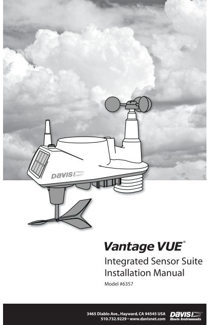
<strong>Integrated</strong> <strong>Sensor</strong> <strong>Suite</strong><br />
<strong>Installation</strong> <strong>Manual</strong><br />
Model #6357<br />
®<br />
3465 Diablo Ave., Hayward, CA 94545 USA<br />
510.732.9229 • www.davisnet.com
Table of Contents<br />
Introduction ........................................................................................................1<br />
Included Components and Hardware .................................................................1<br />
Vantage Vue ISS Components ...............................................................1<br />
Hardware ................................................................................................2<br />
Tools Needed ..........................................................................................2<br />
Preparing the ISS for <strong>Installation</strong> .......................................................................2<br />
Attach the Wind Cups to the Anemometer ............................................3<br />
Attach the Wind Vane ............................................................................3<br />
Install the Rain Collector Tipping Spoon Assembly...............................4<br />
Install the Debris Screen .........................................................................4<br />
Install the Battery ...................................................................................4<br />
Advanced <strong>Installation</strong>s: Confirm the Transmitter ID..............................5<br />
Advanced <strong>Installation</strong>s: Set a New Transmitter ID.................................5<br />
Verify Data from the ISS ........................................................................6<br />
Installing the ISS ................................................................................................7<br />
Choosing a Location for the ISS ........................................................................7<br />
ISS <strong>Installation</strong> Guidelines ................................................................................7<br />
Mounting the ISS ................................................................................................8<br />
Finishing the <strong>Installation</strong> ..................................................................................10<br />
Maintenance and Troubleshooting ...................................................................11<br />
Appendix A: Specifications .............................................................................13<br />
FCC Part 15 Class B Registration Warning<br />
This equipment has been tested and found to comply with the limits for a Class B digital device, pursuant to Part<br />
15 of the FCC Rules. These limits are designed to provide reasonable protection against harmful interference in<br />
a residential installation. This equipment generates, uses, and can radiate radio frequency energy and, if not<br />
installed and used in accordance with the instructions, may cause harmful interference to radio communications.<br />
However, there is no guarantee that interference will not occur in a particular installation. If this equipment does<br />
cause harmful interference to radio or television reception, which can be determined by turning the equipment on<br />
and off, the user is encouraged to try to correct the interference by one or more of the following measures:<br />
• Reorient or relocate the receiving antenna.<br />
• Increase the separation between the equipment and receiver.<br />
• Connect the equipment into an outlet on a circuit different from that to which the receiver is connected.<br />
• Consult the dealer or an experienced radio/TV technician for help.<br />
Changes or modification not expressly approved in writing by Davis Instruments may void the warranty and void<br />
the user's authority to operate this equipment.<br />
FCC ID: IR2DWW6357 IC: 3788A-6357<br />
EC EMC Compliance: This product complies with the essential protection requirements of the EC EMC Directive<br />
2004/108/EC; Low Voltage Directive 2006/95/EC; and Eco-Design Directive 2005/32/EC >.5 watt no-load adaptor.<br />
RoHS Compliant<br />
3465 Diablo Avenue, Hayward, CA 94545-2778 U.S.A.<br />
510-732-9229 • Fax: 510-732-9188<br />
E-mail: info@davisnet.com • www.davisnet.com<br />
®<br />
<strong>Integrated</strong> <strong>Sensor</strong> <strong>Suite</strong> <strong>Installation</strong> <strong>Manual</strong>.<br />
Rev. D, June 1, 2011<br />
Document Part Number: 07395.262<br />
For Vantage Vue Weather Stations and Systems<br />
Vantage Vue ® is a registered trademark of Davis<br />
Instruments Corp., Hayward, CA.<br />
© Davis Instruments Corp. 2011. All rights reserved.<br />
Information in this document subject to change without<br />
notice. Davis Instruments Quality Management<br />
System is ISO 9001 certified.
Introduction<br />
The Vantage Vue® wireless <strong>Integrated</strong> <strong>Sensor</strong> <strong>Suite</strong> (ISS) collects outside weather data<br />
and sends the data wirelessly to a Vantage Vue console via a low-power radio. The ISS is<br />
solar powered and includes a battery back-up.<br />
The Vantage Vue ISS contains a rain collector, temperature/humidity sensor,<br />
anemometer, and wind vane. The temperature/humidity sensor is mounted in a passive<br />
radiation shield to minimize the impact of solar radiation on sensor readings. The<br />
anemometer measures wind speed, and the wind vane measures wind direction.<br />
The <strong>Sensor</strong> Interface Module (SIM) is housed within the ISS and comprises the “brains”<br />
of the Vantage Vue system and the radio transmitter. The SIM collects outside weather<br />
data from the ISS sensors and transmits that data to your Vantage Vue console.<br />
Note:<br />
Your Vantage Vue ISS can transmit to an unlimited number of consoles, so you can purchase additional<br />
consoles to use in different rooms. It can also transmit to Davis Vantage Pro2 consoles and<br />
Davis Weather Envoys as well as Vantage Vue consoles.<br />
Included Components and Hardware<br />
Vantage Vue ISS Components<br />
Rain collector<br />
debris screen<br />
Wind cups<br />
Solar panel<br />
Radiation<br />
shield<br />
Wind vane<br />
Tipping spoon<br />
(rain) assembly<br />
1
Hardware<br />
Hardware included with the Vantage Vue ISS:<br />
U-Bolt<br />
Battery cover with<br />
thumbscrew<br />
3-Volt lithium battery<br />
Backing plate<br />
1/4” lock washers<br />
1/4” hex nuts<br />
Debris screen<br />
0.05” Allen wrench<br />
Note:<br />
If any of the hardware components are missing or not included, contact Customer Service toll free at<br />
1-800-678-3669 about receiving replacement hardware or other components.<br />
Tools Needed<br />
• Adjustable wrench or 7/16” (11 mm) wrench<br />
• Compass or local area map<br />
Preparing the ISS for <strong>Installation</strong><br />
Follow the steps in the order; each builds on tasks completed in previous steps.<br />
Note:<br />
Use a clean, well-lit work table or work area to prepare the ISS for installation.<br />
1. Attach the wind cups to the anemometer<br />
2. Attach the wind vane<br />
3. Install the rain collector tipping spoon assembly<br />
4. Install the debris screen in the rain collector<br />
5. Install the ISS battery to apply power<br />
Note:<br />
At this point, we recommend that you set up your console, and then come back to finish the installation of<br />
the ISS. See your Vantage Vue Console <strong>Manual</strong>.<br />
Additional steps for advanced set up:<br />
• Verify transmitter ID<br />
• Change the transmitter ID for wireless communication, if necessary<br />
6. Verify data from the ISS<br />
2
Attach the Wind Cups to the Anemometer<br />
The Vantage Vue anemometer measures wind speed. The wind cups are mounted on the<br />
anemometer shaft on the top of the ISS assembly.<br />
1. Gently slide the wind cup assembly<br />
down onto the anemometer’s<br />
stainless steel shaft as far as it will<br />
go, as shown.<br />
2. Use the Allen wrench provided to<br />
tighten the set screw near the top of<br />
the “hub” section of the wind cups,<br />
as shown. Ensure that the set screw<br />
is screwed in fully and is tight.<br />
3. Pull gently on the hub to ensure<br />
that the anemometer is securely<br />
fastened to the shaft.<br />
4. Spin the wind cups to make sure<br />
they spin freely.<br />
Install cups onto<br />
stainless steel shaft.<br />
Tighten set screw<br />
with Allen wrench.<br />
Note:<br />
If the wind cups don’t spin freely, loosen the set screw, remove them from the shaft, and repeat the wind<br />
cup installation process.<br />
Attach the Wind Vane<br />
The Vantage Vue wind vane measures wind direction. The wind vane is mounted on a stainless<br />
steel shaft on the opposite side of the ISS assembly from the wind cups.<br />
1. Hold the ISS assembly on its side with<br />
the anemometer and radiation shields<br />
on your left, the wind vane shaft on<br />
your right and the wind cups away<br />
from you.<br />
2. When the ISS is held in this manner,<br />
the wind vane shaft is horizontal, and<br />
will orient itself so that its flat side will<br />
be facing to the right, as shown.<br />
3. Holding the ISS assembly with your<br />
left hand, grasp the wind vane with<br />
your right hand so that the “arrowhead”<br />
end is pointed down.<br />
4. Gently slide the wind vane onto the wind vane shaft, rotating the wind vane slightly left and<br />
right if necessary, until the end of the shaft is visible and protrudes slightly from the bottom<br />
surface of the wind vane.<br />
5. Secure the wind vane to the shaft by firmly tightening the wind vane set screw with the<br />
Allen wrench provided.<br />
3
Install the Rain Collector Tipping Spoon<br />
Assembly<br />
1. Locate the tipping spoon assembly slot on the<br />
underside of the ISS Base.<br />
2. Insert the wider end of the tipping spoon assembly<br />
into the slot first, sliding it under the raised lip of the<br />
slot.<br />
3. Fit the narrow end into the slot and tighten the<br />
thumbscrew securely.<br />
Tipping spoon<br />
assembly slot<br />
Install the Debris Screen<br />
The Vantage Vue ISS rain collector debris screen captures<br />
debris that may otherwise clog your rain collector.<br />
1. Locate the small black plastic ISS debris screen in your<br />
hardware package.<br />
The debris screen has four small tabs that hold it in place<br />
in the base of the rain collector.<br />
2. Holding the ISS assembly with one hand, and holding the<br />
debris screen by the top, press it into the opening in the<br />
rain collector until the tabs snap into the opening.<br />
Tipping spoon<br />
assembly<br />
Install the Battery<br />
The Vantage Vue ISS SIM board stores energy from the solar panel for power at night. A 3-<br />
volt lithium battery provides a backup power source. The battery compartment is located on<br />
the underside of the ISS base. The compartment cover is included in the hardware packet.<br />
To install the ISS backup battery.<br />
1. Insert the 3-volt lithium battery into<br />
the ISS battery compartment, being<br />
sure to match the “+” sign on the<br />
battery with the “+” sign embossed<br />
on the inside of the battery<br />
compartment.<br />
2. Ensure that the battery is properly in<br />
place, install the battery compartment<br />
cover, and tighten the thumbscrew.<br />
Transmitter ID<br />
pushbutton<br />
Transmitter ID<br />
LED<br />
Battery<br />
compartment<br />
Battery compartment<br />
cover<br />
To verify power, wait 30 seconds<br />
then push and release the white transmitter ID pushbutton next to the battery compartment.<br />
The green transmitter ID LED next to the battery compartment will illuminate when you<br />
press the pushbutton.<br />
Note:<br />
Press the pushbutton once and release it. Do not press it multiple times or hold it down.<br />
4
When you release the pushbutton, the LED will blink once (indicating transmitter ID 1),<br />
then begin to flash every 2.5 seconds to show transmission of a data packet. This flashing<br />
will stop within a few minutes to conserve battery life.<br />
Note:<br />
If you have not already set up and powered your Vantage Vue console, do so before continuing with the<br />
ISS installation. For best reception, the console and ISS should be at least 10 feet (3 meters) apart.<br />
3. The console acquires the radio signal and populates data fields. This usually occurs quickly,<br />
but in some enviromental conditions it can take up to 10 minutes.<br />
Advanced <strong>Installation</strong>s: Confirm the Transmitter ID of the ISS<br />
Your Vantage Vue console can be used to listen to a Vantage Pro2 ISS instead of a Vantage<br />
Vue ISS, and an optional anemometer transmitter kit.<br />
Note:<br />
If you are using only the Vantage Vue console and ISS, and there are no other Davis weather stations<br />
nearby, you can skip to “Verify Data from the ISS” on page 6.<br />
In order to communicate, the console and ISS<br />
must have the same transmitter ID. At the<br />
factory, both IDs are set to a default of number<br />
1. To confirm the transmitter ID of your<br />
Vantage Vue ISS:<br />
1. Push and release the transmitter ID<br />
pushbutton once. It will illuminate and go<br />
off when you release it.<br />
2. After a short pause, it will blink one or<br />
more (up to 8) times. Note the number of<br />
times the transmitter ID LED blinks, indicating<br />
its transmitter ID.<br />
Transmitter ID<br />
pushbutton<br />
Transmitter ID<br />
LED<br />
Unless you have intentionally changed your transmitter ID, the LED should blink one time<br />
because the default transmitter ID for the ISS is “1.” If you have changed the ID, the LED<br />
should blink the number of times equal to the ID you have set (i.e., twice for an ID of ‘2,’<br />
three times for an ID of ‘3,’ etc.).<br />
After blinking the transmitter ID, the light will begin to flash every 2.5 seconds, indicating<br />
packet transmission.<br />
Note:<br />
Note:<br />
The transmitter on the ISS and receiver on the console will communicate with each other only when both<br />
are set to the same transmitter ID.<br />
If you hold the pushbutton too long and accidentally enter the “set new transmitter ID” mode when you did<br />
not want to, simply release the pushbutton and wait four seconds. As long as you do not press the pushbutton<br />
again, the original transmitter ID will remain in effect.<br />
Advanced <strong>Installation</strong>s: Set a New Transmitter ID on the ISS<br />
Note:<br />
In most cases, it will not be necessary to change the transmitter ID. If it is necessary to change the transmitter<br />
ID, you must use the same ID for the ISS and console.<br />
The Vantage Vue ISS transmits weather information to the Vantage Vue console using one of<br />
eight selectable transmitter IDs. The default transmitter ID for both the ISS and the Vantage<br />
Vue console is 1. Change the transmitter ID if another Davis Instruments wireless weather station<br />
is operating nearby and already uses transmitter ID 1, or if you have an optional Ane-<br />
5
mometer Transmitter Kit with ID 1.<br />
To set a new transmitter ID:<br />
1. Push and hold the transmitter ID pushbutton until the LED begins flashing quickly. This<br />
indicates it is in the setup mode.<br />
2. Release the pushbutton, and the LED will go dark.<br />
3. Push the pushbutton the number of times equal to your desired new transmitter ID. That is,<br />
if you want to change the ID to “3,” push the pushbutton three times; for a desired ID of<br />
“4,” push the pushbutton four times.<br />
After four seconds have elapsed with no further presses, the LED will blink the same number<br />
of times as the new transmitter ID. (After blinking the transmitter ID number, the light<br />
will begin to flash each time a packet is transmitted, about every 2.5 seconds.)<br />
Verify Data from the ISS<br />
To verify reception of ISS data by the Vantage Vue console, you will need your powered-up<br />
console and the ISS. For best reception, the console and ISS should be at least 10 feet (3<br />
meters) apart.<br />
1. If the console is in Setup Mode, press and hold DONE until the Current Weather screen<br />
displays. The antenna icon appears under the wind compass rose. Watch this icon to see<br />
that “transmission waves” appear, indicating reception of a packet.<br />
<strong>Sensor</strong> readings from the ISS should display on the screen within a few minutes.<br />
2. At the top right corner of the screen, look for the outside temperature.<br />
3. Gently spin the wind cups to check wind speed, pressing the WIND button on the console<br />
to alternate between speed and direction in the windcompass rose.<br />
4. Gently turn the wind vane, and allow 5 seconds for the wind direction display to stabilize<br />
before moving it again.<br />
Note:<br />
A good way to ensure that your console is listening to your ISS and not another Davis station nearby, is to<br />
make sure the wind values displayed match your wind vane’s direction in reference to the solar panels,<br />
which are assumed to be facing south. For example, if you move the vane to point directly away from the<br />
ISS, the console should show a wind direction of south; if you then turn the vane 180° so it is pointed<br />
back at the radiation shield, the wind direction on the console should change to north.<br />
5. Approximately one minute after acquisition of the signal, the outside relative humidity<br />
reading should be displayed on the console, below the outside temperature display.<br />
6. Confirm rain display. On your console screen, select the RAIN DAY display. (See Vantage<br />
Vue Console <strong>Manual</strong>.). Carefully hold your ISS over a sink and, while watching the RAIN<br />
DAY display on your console, slowly pour one-half cup of water into the Rain Collector.<br />
Wait two seconds to see if the display registers a rain reading.<br />
Note:<br />
This method confirms that the rain display is functioning. It cannot be used to verify accuracy.<br />
7. Current data displayed on the console confirms successful communication.<br />
Note:<br />
In some cases it may take as long as ten minutes for a reading to register on your console.<br />
If communication problems exist between the wireless ISS and the console, see<br />
“Troubleshooting ISS Reception” on page 12.<br />
6
Installing the ISS<br />
Choosing a Location for the ISS<br />
The ISS assembly includes the rain collector, wind vane, anemometer, temperature and<br />
humidity sensors, radiation shield, and SIM housing. You will use the U-bolt and associated<br />
nuts and washers that are included with your ISS mounting hardware package to install the ISS<br />
on a pole. (See “Hardware” on page 2.)<br />
To ensure that the Vantage Vue weather station performs at its best, use these guidelines to<br />
select the optimum mounting location for the ISS. Be sure to take into consideration ease of<br />
access for maintenance and wireless transmission range when siting the station.<br />
Note:<br />
When selecting a location for installing your ISS, especially on a rooftop, make sure it is a location far<br />
from power lines. Seek professional help if you are uncertain about the safety of your installation.<br />
ISS <strong>Installation</strong> Guidelines<br />
Note:<br />
These siting guidelines reflect an ideal condition. Rarely is it possible to create the perfect installation.<br />
The better the siting, the more accurate your data will be.<br />
• Place the ISS away from sources of heat such as chimneys, heaters, air conditioners and<br />
exhaust vents.<br />
• Place the ISS at least 100' (30 m) away from any asphalt or concrete roadway that readily<br />
absorbs and radiates heat from the sun. Avoid installations near fences or sides of buildings<br />
that receive a lot of sun during the day.<br />
• Install the ISS as level as possible to ensure accurate rain and wind measurements. Use the<br />
built in bubble level on the top of the ISS, just above the solar panel, to make sure the ISS<br />
is level.<br />
• In the Northern Hemisphere, the solar panel should face south for maximum sun exposure.<br />
• In the Southern Hemisphere, the solar panel should face north for maximum sun exposure.<br />
SOUTH<br />
(in the Northern<br />
Hemisphere)<br />
NORTH<br />
(in the Southern<br />
Hemisphere)<br />
Solar Panel<br />
Note:<br />
If you install the ISS with the solar panel pointing in a direction other than south, you will need to use the<br />
wind direction calibration function in the Vantage Vue console in order to obtain accurate wind direction<br />
readings. See Vantage Vue Console <strong>Manual</strong> for more information.<br />
7
ISS <strong>Installation</strong> Guidelines<br />
• Ideally, mount the ISS so that it is between 5’ (1.5 m) and 7’ (2.1 m) above the ground in<br />
the middle of a gently sloping or flat, regularly mowed grassy or naturally landscaped area<br />
that drains well when it rains. You can also mount the ISS on the roof, between 5’ (1.5 m)<br />
and 7’ (2.1 m) above the roof surface. For areas with average maximum yearly snow<br />
depths over 3’ (0.9 m), mount the ISS at least 2’ (0.6 m) above this depth.<br />
• Never install the ISS where it will be directly sprayed by a sprinkler system.<br />
• Avoid installations near bodies of water such as swimming pools or ponds.<br />
• Do not locate the ISS under tree canopies or near the sides of buildings that create “rain<br />
shadows.” For heavily forested areas, site the ISS in a clearing or meadow.<br />
• Site the ISS in a location with good sun exposure throughout the day.<br />
• For agricultural applications:<br />
• Install the ISS so that it is between 5’ (1.5 m) and 7’ (2.1 m) above the ground and in<br />
the middle of the farm between similar crop types (ie. two orchards, two vineyards,<br />
or two row crops), if possible.<br />
• Avoid areas exposed to extensive or frequent applications of agricultural chemicals<br />
(which can degrade the sensors).<br />
• Avoid installation over bare soils. The ISS performs best when installed over wellirrigated,<br />
regularly mowed grass<br />
• If the last three guidelines cannot be met, install the ISS at the edge of the primary<br />
crop of interest.<br />
Siting guidelines that may affect the anemometer<br />
• For optimal wind data, mount the ISS so that the wind cups are at least 7’ (2.1 m) above<br />
obstructions such as trees or buildings that may obstruct wind flow.<br />
• For optimal wind data, you may mount the ISS on a roof, keeping in mind ease of access<br />
to the ISS for maintenance and safety considerations. Ideally, mount it so that the wind<br />
cups are at least 7’ (2.1 m) above the roof apex.<br />
• The standard for meteorological and aviation applications is to place the anemometer 33’<br />
(10 m) above the ground. Seek professional help for this such installation.<br />
• The standard for agricultural applications is to place the wind cups 6’ (2 m) above the<br />
ground. This is important for evapotranspiration (ET) calculations.<br />
Note:<br />
Note:<br />
For roof mounting, and ease of installation, we recommend using the optional tripod (#7716). For other<br />
installations, use the Mounting Pole Kit (#7717).<br />
For more detailed siting suggestions, see Application Note #30 on the Davis Support website (http://<br />
www.davisnet.com/support/weather).<br />
Mounting the ISS<br />
The Vantage Vue ISS can only be mounted on the top of a pole or rod.<br />
Note:<br />
A mounting pole is not included with your Vantage Vue ISS and must be purchased separately, either<br />
from Davis Instruments or from your local hardware retailer.<br />
8
ISS <strong>Installation</strong> Guidelines<br />
Recommended Accessories for Pole Mounting<br />
• Use the Mounting Tripod (#7716) for easiest mounting.<br />
• Use the Mounting Pole Kit (#7717) to raise the installation height of the ISS by up to<br />
37.5" (0.95 m).<br />
General Guidelines for Installing on a Pole<br />
• With the supplied U-bolt, the ISS can be mounted on a pole or rod having an outside<br />
diameter ranging from 1" to 1.75" (25 – 44 mm).<br />
• To mount on a smaller pole, obtain a U-bolt that fits the base openings but that has a longer<br />
threaded section. If mounting the ISS on a smaller pole with the included U-bolt, the<br />
threaded sections of the U-bolt will be too short to securely mount the ISS.<br />
C-shaped<br />
bracke<br />
Installing the ISS on a Pole<br />
1. If you are mounting your ISS on a Davis Mounting Tripod or the pole included with a<br />
Davis Mounting Pole Kit, follow the instructions included with those Davis products for<br />
proper installation.<br />
If you are not using one of these Davis products, mount on a galvanized steel pole having<br />
an outside diameter ranging from 1" to 1.75" (25 – 44 mm).<br />
Note:<br />
It is important that the mounting pole be plumb. You may wish to use a level such as a magnetic ”torpedo<br />
level” to assure that the ISS, when mounted on top of the pole, will be level.<br />
2. Using the illustration above as a guide, hold the ISS so that the wind cups and radiation<br />
shield are on the left and gently place the ISS on top of the pole.<br />
3. While holding the mounting base of the ISS against the pole, place the two ends of the U-<br />
bolt around the pole and through the two holes in the C-shaped bracket on the base.<br />
4. Slide the metal backing plate over the bolt ends where they extend out from the far side of<br />
the bracket.<br />
5. Secure the backing plate with a lock washer and hex nut on each of the bolt ends, as shown<br />
in the illustration.<br />
6. Tighten the hex nuts with your fingers only so that the ISS is just secure enough on the<br />
pole for you to release your grip.<br />
9
ISS <strong>Installation</strong> Guidelines<br />
7. If you are in the Northern Hemisphere, rotate the ISS on the pole so that the solar panel is<br />
facing south; if you are in the Southern Hemisphere, rotate the ISS so that the solar panel is<br />
facing north. The more precisely the solar panels face due south or north, the more accurate<br />
your wind direction readings will be.<br />
Note:<br />
Do not rely on a compass unless it is properly calibrated. In North America there can be up to 15° variation<br />
between true north and a raw compass reading.<br />
8. When the ISS is properly oriented, tighten the hex nuts with a wrench. Do not exceed 96<br />
inch-pounds (10.8 newton-meters) of torque.<br />
Note:<br />
You can refer to the bubble level on the top of the ISS to make sure it is as level as possible.<br />
Finishing the <strong>Installation</strong><br />
The wind vane is calibrated at the factory to be accurate when the solar panel is pointing south.<br />
If your solar panel does not point south, you must calibrate your console so that it displays<br />
accurate wind direction readings. In any case, you can also calibrate your console to fine-tune<br />
your station for greatest accuracy. Refer to your Vantage Vue Console <strong>Manual</strong> to calibrate your<br />
console.<br />
Note:<br />
Calibration must be done if you are in the Southern Hemisphere, or if you are in the Northern Hemisphere<br />
and cannot install your ISS with the solar panel facing south.<br />
Clearing Data Collected During Testing and <strong>Installation</strong><br />
Now that the ISS is mounted outside, any data that was collected and stored in the console<br />
during testing and mounting should be cleared.<br />
To clear all the collected data on the console:<br />
On the console, press WIND so that selection arrow appears adjacent to the wind data on<br />
the display. Confirm that wind speed is displayed on the compass rose.<br />
Press 2ND, then press and hold CLEAR for at least six seconds and until you see<br />
“CLEARING NOW” in the weather center.<br />
10
Maintenance and Troubleshooting<br />
Maintenance<br />
Cleaning the Radiation Shield<br />
The outer surface of the radiation shield should be cleaned when there is excessive dirt and<br />
build-up on the plates. Use a damp cloth to clean the outer edge of each ring.<br />
Note:<br />
Spraying down or using water excessively to clean the radiation shield can damage the sensitive sensors<br />
or alter the data the ISS is transmitting.<br />
Check the radiation shield for debris or insect nests at<br />
least once a year and clean when necessary. A buildup<br />
of material inside the shield reduces its effectiveness<br />
and may cause inaccurate temperature and humidity<br />
readings.<br />
1. Using a Phillips head screwdriver, loosen the two<br />
#6 x 2 1 / 2 ” screws holding the five radiation shield<br />
plates together, as shown.<br />
2. Taking care to maintain the order in which the five<br />
plates are assembled, separate the plates as shown<br />
and remove all debris from inside the shield.<br />
3. Reassemble the plates in the same order in which<br />
they were disassembled, and fasten them together<br />
using a Phillips head screwdriver to tighten the #6<br />
x 2 1 / 2 ” screws, as shown.<br />
Solid plates,<br />
drain holes<br />
toward<br />
mounting pole<br />
Cleaning the Rain Collector, Debris<br />
Screen, and Tipping Spoon Module<br />
To maintain accuracy, thoroughly clean the rain collector cone and debris screen as needed or<br />
at least once a year.<br />
Note:<br />
Cleaning the rain collector and tipping spoon may cause false rain readings. See “Clearing Data Collected<br />
During Testing and <strong>Installation</strong>” on page 10.<br />
1. Use a damp, soft cloth to remove any debris from the rain collector and debris screen.<br />
2. Use pipe cleaners to clear any debris remaining in the screen.<br />
3. When all parts are clean, rinse with clear water.<br />
To clean the tipping spoon assembly, it must first be removed from the ISS base.<br />
11
Troubleshooting<br />
1. Unscrew the thumbscrew securing the tipping spoon<br />
assembly to the ISS base. Slide the assembly down and<br />
away from the base.<br />
2. Use a damp, soft cloth to gently remove any debris from<br />
the tipping spoon assembly, being careful not to damage<br />
any moving parts or scratch the spoon.<br />
3. When all parts are clean, rinse with clear water, and<br />
replace the assembly. (See “Install the Rain Collector<br />
Tipping Spoon Assembly” on page 4.)<br />
Troubleshooting<br />
Troubleshooting ISS Reception<br />
If the console isn’t displaying data from the ISS:<br />
1. Verify that the ISS and console are powered and that the console is not in Setup Mode. (See<br />
Vantage Vue Console <strong>Manual</strong>.)<br />
2. Make sure that the ISS battery is properly installed.<br />
3. Walk around the room with the console, standing for a few moments in various locations, to<br />
see if you are picking up signals from the ISS. Look on the screen below the wind compass<br />
rose for the small graphic of a radio antenna.<br />
Note:<br />
If you do not see the antenna icon, press 2ND and SETUP to enter Setup Mode, then press DONE to<br />
return to the Current Weather Screen. The icon should appear.<br />
Note:<br />
4. Small “transmission waves” display above the antenna icon and toggle on and off when the<br />
console receives a transmission.<br />
If you do not see the antenna’s transmission wave graphic slowly blinking, regardless of<br />
where you stand with the console, you should call Technical Support.<br />
5. If the Transmitter ID LED does not light after pressing the Transmitter Pushbutton, there is<br />
a problem with the ISS transmitter. Call Technical Support.<br />
6. If, after pressing the Transmitter Pushbutton, the Transmitter ID LED flashes every 2.5 seconds<br />
(indicating transmission) but your console isn’t picking up a signal anywhere in the<br />
room, it could be related to one of the following causes:<br />
• You changed the ISS Transmitter ID at the ISS or console, but not at both.<br />
• Reception is being disrupted by frequency interference from outside sources, or the distance<br />
and barriers are too great.<br />
Interference has to be strong to prevent the console from receiving a signal while in the same room as the<br />
ISS.<br />
• There is a problem with the Vantage Vue console.<br />
7. If a problem with receiving the wireless transmission still exists, please contact Technical<br />
Support.<br />
Note: See “Contacting Davis Instruments” on page 12.<br />
12
Troubleshooting<br />
Note:<br />
Problems Using Two Transmitting Stations<br />
A single Vantage Vue console can receive signals from one ISS, either a Vantage Vue or a<br />
Vantage Pro2 ISS, and an optional anemometer transmitter kit. Make sure the transmitter IDs<br />
are configured correctly. See your Vantage Vue Console <strong>Manual</strong> for information on configuring<br />
transmitter IDs.<br />
Most Common Rain Collector Problem<br />
“My rain data seems too low.”<br />
If the rain collector seems to be under-reporting rainfall, clean the debris screen and<br />
tipping spoon module to clear out any debris.<br />
Most Common Anemometer Problems<br />
“The wind cups are spinning but my console displays 0 mph.”<br />
The wind cups may not be turning the shaft. Remove the cups from the anemometer by<br />
loosening the set screw. Put the cups back onto the shaft and make sure to slide them<br />
down the shaft as far as possible. Retighten the set screw.<br />
“The wind cups don’t spin or don’t spin as fast as they should.”<br />
The anemometer may be located where wind is blocked by something, or there may be<br />
friction interfering with the cups’ rotation. Remove the wind cups by loosening the set<br />
screw, and clear out any insects or debris which may be interfering with the cup rotation.<br />
Turn the shaft the cups rotate on. If it feels gritty or stiff, contact Davis Technical<br />
Support.<br />
Do not lubricate the shaft or bearings in any way.<br />
“Readings aren’t what I expected them to be.”<br />
Comparing data from your ISS to measurements from TV, radio, newspapers, or a<br />
neighbor is NOT a valid method of verifying your readings. Readings can vary<br />
considerably over short distances. How you site the ISS and anemometer can also make<br />
a big difference. If you have questions, contact Davis Technical Support.<br />
Contacting Davis Instruments<br />
If you have questions about the ISS or Vantage Vue system, or encounter problems installing<br />
or operating the weather station, please contact Davis Technical Support.<br />
Note:<br />
Please do not return items to the factory for repair without prior authorization.<br />
(510) 732-7814 – Technical Support phone, Monday – Friday, 7:00 a.m. – 5:30 p.m. Pacific<br />
Time.<br />
(510) 670-0589 – Technical Support Fax.<br />
support@davisnet.com – E-mail to Technical Support.<br />
info@davisnet.com – General e-mail.<br />
www.davisnet.com – Download manuals and specifications from the Support section. Watch<br />
for FAQs and other updates. Subscribe to the e-newsletter.<br />
13
Appendix A: Specifications<br />
See complete specifications for your Vantage Vue station on our website:<br />
www.davisnet.com<br />
<strong>Integrated</strong> <strong>Sensor</strong> <strong>Suite</strong> (ISS) Specifications<br />
Operating Temperature...................................-40° to +150°F (-40° to +65°C)<br />
Non-operating (Storage) Temperature ............-40° to +158°F (-40° to +70°C)<br />
Current Draw (ISS SIM only)...........................0.20 mA (average), 30 mA (peak) at 3.3<br />
VDC<br />
Solar Power Panel (ISS SIM) ..........................0.5 Watts<br />
Battery (ISS SIM)............................................CR-123 3-Volt Lithium cell<br />
Battery Life (3-Volt Lithium cell) ......................8 months without sunlight - greater than<br />
2 years depending on solar charging<br />
Connectors, <strong>Sensor</strong> ........................................Pogo Pins<br />
Cable Type .....................................................6-conductor, 28 AWG<br />
Wind Speed <strong>Sensor</strong> .......................................Wind cups with magnetic switch<br />
Wind Direction <strong>Sensor</strong> ...................................Wind vane with magnetic encoder<br />
Rain Collector Type .......................................Tipping spoon, 0.01" per tip (0.2 mm<br />
with metric rain cartridge, Part No.<br />
7345.319), 18.0 in 2 (116 cm 2 ) collection<br />
area<br />
Temperature <strong>Sensor</strong> Type ..............................PN Junction Silicon Diode<br />
Relative Humidity <strong>Sensor</strong> Type .......................Film capacitor element<br />
Housing Material.............................................UV-resistant ABS & ASA plastic<br />
Update Interval by <strong>Sensor</strong><br />
WIND TEMPERATURE RAIN HUMIDITY BAR<br />
Barometric Pressure<br />
Inside Humidity<br />
Outside Humidity<br />
Dew Point<br />
Rainfall Amount<br />
Rain Storm Amount<br />
Rain Rate<br />
Inside Temperature<br />
Outside Temperature<br />
Heat Index<br />
Wind Chill<br />
Wind Speed<br />
Wind Direction<br />
Direction of High Speed<br />
1 min.<br />
1 min.<br />
50 sec.<br />
10 sec.<br />
20 sec.<br />
20 sec.<br />
20 sec.<br />
1 min.<br />
10 sec.<br />
10 sec.<br />
10 sec.<br />
2.5 sec.<br />
2.5 sec.<br />
2.5 sec.<br />
14