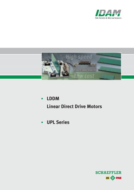
LDDM Linear Direct Drive Motors; UPL Series - Schaeffler Group
LDDM Linear Direct Drive Motors; UPL Series - Schaeffler Group
LDDM Linear Direct Drive Motors; UPL Series - Schaeffler Group
You also want an ePaper? Increase the reach of your titles
YUMPU automatically turns print PDFs into web optimized ePapers that Google loves.
<strong>LDDM</strong><br />
<strong>Linear</strong> <strong>Direct</strong> <strong>Drive</strong> <strong>Motors</strong><br />
<strong>UPL</strong> <strong>Series</strong><br />
1
The Perfect <strong>Drive</strong> for Every Application.<br />
INA - <strong>Drive</strong>s & Mechatronics AG & Co. KG,<br />
a member of the <strong>Schaeffler</strong> <strong>Group</strong>, is a<br />
specialist for linear and rotary direct<br />
drives. To complement these products,<br />
we also offer directly driven positioning<br />
systems and all the necessary controllers<br />
and mechatronic assemblies.<br />
In addition to standard products, IDAM<br />
also develops and produces customised<br />
drive solutions.<br />
In modern machines and equipment,<br />
direct drives are increasingly replacing<br />
standard drive solutions because of<br />
ever-stricter requirements for dynamics,<br />
precision and cost-effectiveness.<br />
<strong>Direct</strong>ly linking the motor and the moving<br />
mass increases the dynamic and<br />
static rigidity, enabling high-performance<br />
positioning movements.<br />
<strong>Direct</strong> drives are low wearing, which<br />
reduces maintenance and operating<br />
costs while also increasing availability.<br />
For more than 20 years, teams at IDAM<br />
have been producing direct drives and<br />
complex drive systems for the following<br />
sectors: machine tools and production<br />
machinery, automation, productronics/<br />
semicon, metrology and medical engineering.<br />
Models and simulations are integrated<br />
into the development process for direct<br />
drives and positioning systems, making<br />
the process more efficient.<br />
IDAM has a cutting-edge quality management<br />
system. At IDAM, quality management<br />
is a dynamic process that is<br />
checked daily and continuously<br />
improved. IDAM is certified to<br />
DIN EN ISO 9001: 2008.<br />
Specially developed tools are used to develop and design the engines and<br />
systems, including tools for mechanical and thermal simulation.<br />
IDAM customers can access the results of these simulations to improve their<br />
adjacent constructions.<br />
2
Contents<br />
Product range<br />
Benefits of <strong>Linear</strong> <strong>Direct</strong> <strong>Drive</strong>s ..................................................................................4<br />
<strong>UPL</strong> <strong>Linear</strong> <strong>Motors</strong> – Applications, benefits ........................................................................5<br />
Safety Instructions for Handling <strong>UPL</strong> <strong>Linear</strong> <strong>Motors</strong> ..................................................................6<br />
Installation and Insulation Coordination for <strong>UPL</strong> <strong>Linear</strong> <strong>Motors</strong> ........................................................7<br />
Assembly ....................................................................................................8<br />
Pin Assignment ...............................................................................................9<br />
Storing <strong>UPL</strong> <strong>Linear</strong> <strong>Motors</strong> .....................................................................................11<br />
Type Designation. ............................................................................................12<br />
<strong>UPL</strong> Overview – Sizes .........................................................................................13<br />
<strong>UPL</strong>1 .......................................................................................................14<br />
<strong>UPL</strong>2.......................................................................................................16<br />
<strong>UPL</strong>3.......................................................................................................18<br />
Planning Note for Operating <strong>UPL</strong> <strong>Motors</strong> in Parallel .................................................................21<br />
General information<br />
Check List for Your Enquiry .....................................................................................22<br />
Technical Information and Consulting Services ....................................................................24<br />
IDAM Worldwide .............................................................................................25<br />
Notes ......................................................................................................26<br />
Overview of Publications ......................................................................................27<br />
3
Benefits of <strong>Linear</strong> <strong>Direct</strong> <strong>Drive</strong>s<br />
Performance<br />
Operating costs<br />
Design<br />
1. No transformation of the movement<br />
pattern<br />
There is no elasticity, no play, no friction<br />
and no hysteresis in the drive train<br />
resulting from transmission or coupling<br />
elements.<br />
2. Compact motor<br />
The large feed force for a relatively small<br />
moving mass means very high acceleration<br />
is possible. The force can be used<br />
from speed 0 up to the velocity limit.<br />
3. <strong>Direct</strong> position measurement<br />
<strong>Direct</strong> position measurement and the<br />
rigid mechanical structure enable highly<br />
precise, dynamic positioning operations.<br />
1. No additional moving parts<br />
This reduces the effort of installing,<br />
adjusting and maintaining the drive<br />
assembly.<br />
2. Minimal wear in the drive train<br />
The drive train has a very long service<br />
life, even if subjected to extreme alternating<br />
loads. This reduces machine<br />
downtime.<br />
3. High availability<br />
In addition to the longer service life and<br />
reduced wear, the sturdiness of the linear<br />
motors increases their availability.<br />
1. Small installation space<br />
A compact design makes it possible to<br />
create low volume drive modules.<br />
2. Few parts<br />
The well-engineered design makes it<br />
easier to integrate the motor parts into<br />
the machine concept.<br />
There are only a few, very sturdy parts,<br />
which reduces the fail rate.<br />
3. Variety of design variants<br />
This optimises the integration of the<br />
motor parts design in the machine<br />
concept.<br />
4
<strong>UPL</strong> <strong>Linear</strong> <strong>Motors</strong><br />
Applications, benefits<br />
Applications<br />
Benefits<br />
• Pick and place tasks<br />
• Vertical installation (Z axis) because of<br />
small own mass moved<br />
• Applications that require maximum<br />
path precision or a constant speed<br />
The <strong>UPL</strong> linear motors are ideal for applications<br />
in the following areas:<br />
• Semiconductor production<br />
• Electronics assembly<br />
• Measuring and inspection systems<br />
• Precision automation<br />
• Medical engineering<br />
• Low-cost applications in the mass<br />
market<br />
• Minimum current rise times thanks to<br />
ironless primary part (good power/<br />
mass ratio)<br />
• High acceleration capacity<br />
• Very high end speed<br />
• Highly efficient<br />
• Very good synchronisation (no cogging<br />
forces, very low load pulsation)<br />
• Compact design<br />
• High performance and low cost<br />
• Excellent static and dynamic load<br />
rigidity<br />
• Precise positioning without overshoot<br />
• High reliability and long service life<br />
• Non-contact operation without wear<br />
• Easy to adapt, making it adjustable to<br />
special solutions<br />
• Automatic production means high<br />
quality standards<br />
<strong>UPL</strong> system solution<br />
<strong>UPL</strong> primary parts<br />
5
Safety Instructions for Handling <strong>UPL</strong> <strong>Linear</strong> <strong>Motors</strong><br />
LIFE THREATENING<br />
Dangerous magnetic fields!<br />
LIFE THREATENING<br />
Dangerous voltages!<br />
WARNING<br />
Strong magnetic fields!<br />
Magnetic fields can cause serious health<br />
problems or death in persons with active<br />
implants.<br />
Persons with pacemakers and/or metal<br />
implants, pregnant women and persons<br />
with hearing devices should not come<br />
any closer than 120 mm to the linear<br />
direct drive.<br />
RISK OF BURNS<br />
Dangerous temperatures!<br />
In operation the <strong>UPL</strong> linear motor may<br />
heat up to max. 140 °C.<br />
There is a very high risk of burns.<br />
Never touch the motor when in operation<br />
or soon after switching off.<br />
If the coil system is mechanically damaged,<br />
life-threatening voltages of up to<br />
the operating voltage may be present on<br />
the motor or magnet base.<br />
The surfaces of the motors must not be<br />
damaged.<br />
To protect against dangerous voltages,<br />
all primary and secondary parts must be<br />
connected to the protective earth conductor,<br />
especially in the case of nonconductive<br />
assemblies. In accordance<br />
with DIN EN 60204, a protective earth<br />
system shall be set up for the entire<br />
machine in order to connect all the conductive<br />
structural components.<br />
Strong forces may arise when handling<br />
secondary parts. There is a risk of<br />
crushed limbs.<br />
Ensure that there is enough space<br />
between secondary parts and between<br />
secondary parts and ferromagnetic<br />
parts.<br />
When stacking, separate the secondary<br />
parts by rotating the assemblies. The<br />
spacers must remain on the magnets<br />
until the individual secondary parts are<br />
securely separated. Warning, sharp<br />
edges!<br />
Keep ferromagnetic material away from<br />
the motors. When working on motors,<br />
only use tools with no ferromagnetic<br />
properties.<br />
Also keep electronic devices and data<br />
carriers away from the secondary parts'<br />
magnetic fields.<br />
<strong>UPL</strong> linear motors are only intended to be used as direct drives in industrial applications.<br />
In particular, the motors must not be operated underwater, in oil, in refrigerants<br />
or in explosive environments. They must only be operated in the expressly<br />
specified configuration and combination of components. Any other use is considered<br />
contrary to the intended use. The operator bears sole liability for any resultant<br />
damages.<br />
6
Installation and Insulation Coordination for <strong>UPL</strong> <strong>Linear</strong> <strong>Motors</strong><br />
<strong>UPL</strong> linear motors are not designed to be<br />
connected directly to the mains supply;<br />
instead, they have to be operated via an<br />
electronics assembly, generally a servo<br />
amplifier. Connecting the motors directly<br />
to the mains will destroy them.<br />
The motors must not be used in potentially<br />
explosive areas or in the vicinity of<br />
oils, gases, acids, vapours, dust, etc.<br />
The manufacturer of the machine or<br />
plant should compile a risk assessment<br />
and derive measures to ensure safe<br />
operation of the entire system.<br />
Installation work must be carried out<br />
when the system is de-energised only,<br />
and measures must be taken to prevent<br />
accidental restoration of power.<br />
The maximum permissible rated voltage<br />
must not be exceeded.<br />
Use shielded lines and connect the<br />
shielding to the earth potential on the<br />
servo amplifier as extensively as possible.<br />
The start of designated operation for a<br />
whole system or machine that integrates<br />
one or more <strong>UPL</strong> linear motors must not<br />
take place until it has been established<br />
that all the relevant provisions of the<br />
EU <strong>Direct</strong>ives and all the country-specific<br />
accident prevention regulations are<br />
fulfilled. This primarily involves EU<br />
Ma chinery <strong>Direct</strong>ive 2006/42/EC and<br />
EU <strong>Direct</strong>ive on EMC 2004/108/EC.<br />
Furthermore, DIN EN 60664-1 (VDE 0110-1):<br />
2008-01 on insulation coordination shall<br />
be observed. According to DIN EN<br />
60664-1, <strong>UPL</strong> linear motors are operating<br />
equipment that is not supplied<br />
directly from the low voltage grid. The<br />
maximum effective voltage that can<br />
occur in the system shall be used to<br />
dimension the basic insulation. The rate<br />
impulse voltage is specified as 0.8 kV,<br />
resulting in the following minimum<br />
requirements: Clearance L S = 0.2 mm,<br />
creepage distance L K = 0.75 mm<br />
Personnel who work with <strong>UPL</strong> linear<br />
motors should fulfil the following technical<br />
requirements:<br />
Transport: knowledge of handling electrostatically<br />
sensitive components<br />
Installation: specialists with electrotechnical<br />
training and knowledge of safety<br />
guidelines for electrical and automation<br />
technology<br />
Commissioning: comprehensive knowledge<br />
of electrical, automation and drive<br />
technology<br />
Knowledge of the machine safety laws is<br />
essential.<br />
7
Assembly<br />
Assembling primary and secondary parts: <strong>UPL</strong>X-L-D-O and <strong>UPL</strong>X-L-O-O<br />
(0.05)<br />
A<br />
c<br />
Type<br />
a [mm] b [mm] c [mm] d [mm]<br />
A<br />
<strong>UPL</strong>1-L-D-O / -O-O<br />
16.0<br />
44.5<br />
6.5 ± 0.05<br />
0.5<br />
d<br />
d<br />
<strong>UPL</strong>2-L-D-O / -O-O<br />
14.8<br />
51.0<br />
5.9 ± 0.05<br />
0.4<br />
b<br />
<strong>UPL</strong>3-L-D-O / -O-O<br />
21.4<br />
70.0<br />
8.5 ± 0.05<br />
0.5<br />
a<br />
Notes on assembly: Clear the area of the solder contacts in the adjacent construction<br />
by at least 1 mm in depth.<br />
Assembling primary and secondary parts: <strong>UPL</strong>X-L-D-T and <strong>UPL</strong>X-L-O-T<br />
(0.05)<br />
A<br />
c<br />
Type<br />
a [mm]<br />
b [mm] c [mm] d [mm] M T * [Nm]<br />
<strong>UPL</strong>1-L-D-T / -O-T<br />
16.0<br />
44.5<br />
3.5 ± 0.1<br />
0.5<br />
0.5<br />
b<br />
d<br />
A<br />
<strong>UPL</strong>2-L-D-T / -O-T<br />
14.8<br />
51.0<br />
2.9 ± 0.1<br />
0.4<br />
0.5<br />
d<br />
<strong>UPL</strong>3-L-D-T / -O-T<br />
21.4<br />
70<br />
4.8 ± 0.1<br />
0.5<br />
1.0<br />
a<br />
*M T : Fastening torque for gib<br />
The gib can be mounted on the left or right side, as desired. The chamfer and slot<br />
have to be placed on the motor side. The gib and fastening screws are included in<br />
the delivery. Use only the stainless screws provided to attach the gib.<br />
The type plate with serial number is enclosed and has to be attached visible near the primary part to ensure clear identification.<br />
8
Pin Assignment<br />
For <strong>UPL</strong>1-50-X-X-PRIM, <strong>UPL</strong>1-100-X-X-PRIM, <strong>UPL</strong>2-34-X-X-PRIM<br />
Through-hole terminal Ø 1.0 mm<br />
PE<br />
U V W<br />
PE<br />
0.14 - 0.34 mm 2 /AWG22-26<br />
Ø 2.5<br />
U V W<br />
2.5<br />
Through-hole terminal Ø 1.25 mm<br />
0.14 - 0.50 mm 2 /AWG20-26<br />
Mounting holes are contacted with PE.<br />
For <strong>UPL</strong>2-67-X-X-PRIM, <strong>UPL</strong>2-100-X-X-PRIM<br />
Through-hole terminal Ø 1.25 mm<br />
PE<br />
U<br />
V<br />
W<br />
PE<br />
0.14 - 0.50 mm 2 /AWG20-26<br />
Ø 2.5<br />
Mounting holes are contacted with PE.<br />
U<br />
V<br />
W<br />
For <strong>UPL</strong>3-L-D-O-PRIM, <strong>UPL</strong>3-L-D-T-PRIM<br />
PTC<br />
-KTY+<br />
Ø 2.5<br />
Through-hole terminal Ø 1.25 mm<br />
0.14 - 0.50 mm 2 /AWG20-26<br />
U<br />
V<br />
W<br />
Sensor connections are not allocated for this variant.<br />
Ø2<br />
Hall Hall Hall<br />
KTY +<br />
- S + - S + -<br />
S +<br />
PTC<br />
<br />
PTC<br />
-KTY+<br />
<br />
Ø2<br />
-<br />
+<br />
Ø 2.5<br />
9
PTC<br />
-KTY+<br />
Pin Assignment<br />
Ø 2.5<br />
U V<br />
Ø2<br />
Hall Hall Hall<br />
PTC<br />
- S + - S + - S +<br />
<br />
- +<br />
Ø 2.5<br />
U S W S<br />
For <strong>UPL</strong>3-L-O-O-PRIM, <strong>UPL</strong>3-L-O-T-PRIM<br />
Ø2<br />
PTC<br />
V S U<br />
WV<br />
W<br />
-KTY+<br />
KTY +<br />
<br />
Through-hole terminal Ø 1.00 mm<br />
0.08 - 0.25 mm 2 /AWG24-28<br />
Through-hole terminal Ø 1.25 mm<br />
0.14 - 0.50 mm 2 /AWG20-26<br />
Through-hole terminal Ø 1.00 mm<br />
0.08 - 0.25 mm 2 /AWG24-28<br />
The electrical connection should be set up by a trained electrician in accordance with the cable or pin allocation. Electrical<br />
connections shall be checked in line with the electrical and technical regulations. Correct wiring is essential. Faulty connections<br />
can cause unexpected and uncontrolled motor movements, or destroy electrical or electronic components.<br />
<strong>UPL</strong> linear motor: primary and secondary part<br />
10
Storing <strong>UPL</strong> <strong>Linear</strong> <strong>Motors</strong><br />
General<br />
The <strong>UPL</strong> linear motors developed by<br />
IDAM have a design comparable to a<br />
multi-layered circuit board. As with circuit<br />
board technology, there are special<br />
requirements for handling and storing<br />
the motors in order to ensure the longest<br />
possible service life. The length of<br />
time and conditions under which <strong>UPL</strong><br />
linear motors can be stored depend on<br />
many factors.<br />
Approximate storage time<br />
The approximate storage time is<br />
12 months.<br />
Storage conditions<br />
The motors must be stored in their<br />
sealed original packaging (PE bag sealed<br />
with dry pack) and as close to indoor climate<br />
as possible (25 °C ± 5 °C, max.<br />
60% humidity). Deviations from this<br />
affect the surface, which in turn affects<br />
the ability to form solder joints for the<br />
motor connections. Higher temperatures<br />
accelerate aging processes. Temperature<br />
fluctuation can lead to condensation on<br />
the packaging and motors. The soldering<br />
surface should not be touched or contaminated.<br />
To protect their geometry, <strong>UPL</strong> linear<br />
motors should be stored level and in<br />
their original packaging, where possible.<br />
i<br />
Keep storage times to a minimum. Use a<br />
first in, first out principle in your warehouse<br />
and during further processing.<br />
During processing, give preference to<br />
packages that have already been<br />
opened.<br />
Choose order/released quantities that<br />
ensure processing within the shortest<br />
possible space of time.<br />
i<br />
Packaging should only be opened immediately<br />
before installing the <strong>UPL</strong> linear<br />
motor.<br />
11
Type Designation<br />
<strong>UPL</strong>X - L - X - X - PRIM<br />
Short designation of motor type<br />
<strong>UPL</strong> Ironless multilayer PCB linear motor, primary part<br />
Design characteristics number<br />
1 2t p = 25 mm<br />
2 2t p = 16.5 mm<br />
3 2t p = 30 mm<br />
Length of coil system [mm]<br />
Temperature monitoring, commutation type<br />
D Without sensors<br />
O With sensors (on request)<br />
Mounting type<br />
O Through-hole on side<br />
T Threaded hole vertically in enclosed<br />
gib<br />
Motor part<br />
PRIM Primary part<br />
<strong>UPL</strong>X - L - SEK<br />
Short designation of motor type<br />
<strong>UPL</strong> Ironless multilayer PCB linear motor, secondary part<br />
Design characteristics number<br />
1 2t p = 25 mm<br />
2 2t p = 16.5 mm<br />
3 2t p = 30 mm<br />
Length of secondary part [mm]<br />
Depending on design 1, 2, 3<br />
Motor part<br />
SEK Secondary part<br />
12
<strong>UPL</strong> Overview<br />
Sizes<br />
Primary part Length L PRIM Width W Height H Peak force F p Continuous force F c<br />
type [mm] [mm] [mm] [N] [N]<br />
<strong>UPL</strong>1-50-PRIM<br />
50<br />
38<br />
3.0 ± 0.2<br />
10.4<br />
5<br />
<strong>UPL</strong>1-100-PRIM<br />
100<br />
38<br />
3.0 ± 0.2<br />
20.6<br />
9<br />
<strong>UPL</strong>2-34-PRIM<br />
34<br />
42.2<br />
3.0 ± 0.2<br />
13.8<br />
4.7<br />
<strong>UPL</strong>2-67-PRIM<br />
67<br />
42.2<br />
3.0 ± 0.2<br />
27.5<br />
8.0<br />
<strong>UPL</strong>2-100-PRIM<br />
100<br />
42.2<br />
3.0 ± 0.2<br />
41.5<br />
12.4<br />
<strong>UPL</strong>3-78-PRIM<br />
78<br />
60<br />
4.4 ± 0.3<br />
50<br />
15<br />
<strong>UPL</strong>3-138-PRIM<br />
138<br />
60<br />
4.4 ± 0.3<br />
100<br />
30<br />
<strong>UPL</strong>3-198-PRIM<br />
198<br />
60<br />
4.4 ± 0.3<br />
150<br />
45<br />
<strong>UPL</strong>3-258-PRIM<br />
258<br />
60<br />
4.4 ± 0.3<br />
200<br />
60<br />
H<br />
L PRIM<br />
W<br />
Secondary part Length L SEK Width W Height H<br />
type [mm] [mm] [mm]<br />
<strong>UPL</strong>1-100-SEK<br />
100<br />
30<br />
16<br />
<strong>UPL</strong>1-150-SEK<br />
150<br />
30<br />
16<br />
<strong>UPL</strong>2-66-SEK<br />
66<br />
40<br />
14.8<br />
<strong>UPL</strong>2-99-SEK<br />
99<br />
40<br />
14.8<br />
L SEK<br />
W<br />
<strong>UPL</strong>3-90-SEK<br />
90<br />
50<br />
21.4<br />
H<br />
<strong>UPL</strong>3-120-SEK<br />
120<br />
50<br />
21.4<br />
<strong>UPL</strong>3-390-SEK<br />
390<br />
50<br />
21.4<br />
13
1<br />
3<br />
<strong>UPL</strong>1<br />
Technical data I<br />
L PRIM<br />
(n1-1) xc1<br />
(10.7)<br />
7.5<br />
3.8<br />
4<br />
c 1<br />
Ø3.2<br />
(n x)<br />
3±0.2<br />
9<br />
3.5 ±0.1<br />
30<br />
4<br />
A<br />
38<br />
Ø3.4<br />
(n x)<br />
44.5<br />
A<br />
12.5<br />
c 3 =25<br />
9.5<br />
c 2<br />
(n3-1) xc3<br />
L SEK<br />
L PRIM<br />
(n2-1) xc2<br />
M3<br />
(n x)<br />
3<br />
16<br />
A-A<br />
Variant D-O<br />
(without gib)<br />
16<br />
Variant D-T<br />
(The gib can be mounted<br />
on the left or right side,<br />
as desired.)<br />
Primary part Symbol Unit <strong>UPL</strong>1-50 <strong>UPL</strong>1-100<br />
Block length L PRIM mm 50 100<br />
Variant D-O (without gib)<br />
Mass m g 22 44<br />
Hole spacing c 1 mm 42 46<br />
Number of holes n 1 piece 2 3<br />
Variant D-T (with gib)<br />
Mass m g 30 57<br />
Hole spacing c 2 mm 31 27<br />
Number of holes n 2 piece 2 4<br />
Secondary part Symbol Unit <strong>UPL</strong>1-100-SEK <strong>UPL</strong>1-150-SEK<br />
Length L SEK mm 100 150<br />
Mass m g 230 345<br />
Number of holes n 3 piece 4 6<br />
Length grid 2t p mm 25 25<br />
Tolerance range of values: ±10% • Subject to changes without advance notification, according to technical progress.<br />
14
<strong>UPL</strong>1<br />
Technical data II<br />
Performance data Symbol Unit <strong>UPL</strong>1-50 <strong>UPL</strong>1-100<br />
Max. impulse force (1 s) at I mp F mp N 13.0 25.8<br />
Peak force (3 s) at I p F p N 10.4 20.6<br />
Continuous force not cooled at I c F c N 5 9<br />
Power loss at F p (25 °C) P lp W 35 70<br />
Power loss at F c (25 °C) P lc W 7.9 13.2<br />
Motor constant (25 °C) k m N/√W 1.75 2.50<br />
Electric time constant t el ms 0.075 0.075<br />
Attraction force between PRIM and SEK F a N 0 0<br />
Ripple force (cogging) F r N 0 0<br />
Temperature sensors none none<br />
Pole pair width 2t p mm 25 25<br />
Winding data Symbol Unit <strong>UPL</strong>1-50 <strong>UPL</strong>1-100<br />
Force constant k f N/A rms 4.3 8.6<br />
Back EMF constant, phase-to-phase k u V/(m/s) 3.5 7.0<br />
<strong>Linear</strong> limit speed at F p and U DCL v lim m/s 10 5<br />
Electric resistance, ph-to-ph (25 °C) R 25 Ω 4 8<br />
Inductance, phase-to-phase L mH 0.3 0.6<br />
Max. impulse current (1 s) I mp A rms 3.0 3.0<br />
Peak current (3 s) I p A rms 2.4 2.4<br />
Continuous current not cooled I c A rms 1.15 1.05<br />
Permissible winding temperature J °C 140 140<br />
Thermal time constant t th min 11.5 14.0<br />
DC link voltage (maximum) U DCL V 120 120<br />
Tolerance range of values: ±10% • Subject to changes without advance notification, according to technical progress.<br />
15
3<br />
3<br />
<strong>UPL</strong>2<br />
Technical data I<br />
40<br />
5<br />
A<br />
A<br />
7.6<br />
4<br />
b 1<br />
c 1<br />
L PRIM<br />
(n1-1) xc1<br />
Ø3.2<br />
(n x)<br />
1<br />
8 c 2<br />
(without gib)<br />
3±0.2<br />
16.5 c 3 =33<br />
3<br />
(n3-1) xc<br />
14.8<br />
3<br />
L SEK<br />
A-A<br />
L PRIM<br />
(n2-1) xc<br />
Variant D-O<br />
2<br />
M3<br />
(n x)<br />
2<br />
42.2<br />
Ø4.5<br />
(n x)<br />
Ø7.5<br />
(n x)<br />
2.9 ± 0.1<br />
(10)<br />
8.5<br />
14.8<br />
51<br />
Variant D-T<br />
(The gib can be mounted<br />
on the left or right side,<br />
as desired.)<br />
Primary part Symbol Unit <strong>UPL</strong>2-34 <strong>UPL</strong>2-67 <strong>UPL</strong>2-100<br />
Block length L PRIM mm 34 67 100<br />
Variant D-O (without gib)<br />
Mass m g 15 30 45<br />
Hole spacing c 1 mm 28 59 46<br />
Number of holes n 1 piece 2 2 3<br />
Edge spacing b 1 mm 3 4 4<br />
Variant D-T (with gib)<br />
Mass m g 20 38 57<br />
Hole spacing c 2 mm 18 51 28<br />
Number of holes n 2 piece 2 2 4<br />
Secondary part Symbol Unit <strong>UPL</strong>2-66-SEK <strong>UPL</strong>2-99-SEK<br />
Length L SEK mm 66 99<br />
Mass m g 193 290<br />
Number of holes n 3 piece 2 3<br />
Length grid 2t p mm 16.5 16.5<br />
Tolerance range of values: ±10% • Subject to changes without advance notification, according to technical progress.<br />
16
<strong>UPL</strong>2<br />
Technical data II<br />
Performance data Symbol Unit <strong>UPL</strong>2-34 <strong>UPL</strong>2-67 <strong>UPL</strong>2-100<br />
Max. impulse force (1 s) at I mp F mp N 17.2 35.0 51.0<br />
Peak force (3 s) at I p F p N 13.8 27.5 41.5<br />
Continuous force not cooled at I c F c N 4.7 8.0 12.4<br />
Power loss at F p (25 °C) P lp W 52 104 156<br />
Power loss at F c (25 °C) P lc W 5.96 8.64 14.10<br />
Motor constant (25 °C) k m N/√W 1.9 2.7 3.3<br />
Electric time constant t el ms 0.05 0.05 0.05<br />
Attraction force between PRIM and SEK F a N 0 0 0<br />
Ripple force (cogging) F r N 0 0 0<br />
Temperature sensors none none none<br />
Pole pair width 2t p mm 16.5 16.5 16.5<br />
Winding data Symbol Unit <strong>UPL</strong>2-34 <strong>UPL</strong>2-67 <strong>UPL</strong>2-100<br />
Force constant k f N/A rms 9.9 9.9 9.9<br />
Back EMF constant, phase-to-phase k u V/(m/s) 8.1 8.1 8.1<br />
<strong>Linear</strong> limit speed at F p and U DCL v lim m/s 3.9 3.9 3.9<br />
Electric resistance, ph-to-ph (25 °C) R 25 Ω 18 9 6<br />
Inductance, phase-to-phase L mH 0.90 0.45 0.30<br />
Max. impulse current (1 s) I mp A rms 1.73 3.50 5.20<br />
Peak current (3 s) I p A rms 1.39 2.80 4.17<br />
Continuous current not cooled I c A rms 0.47 0.80 1.25<br />
Permissible winding temperature J °C 140 140 140<br />
Thermal time constant t th min 7.1 8.0 8.5<br />
DC link voltage (maximum) U DCL V 120 120 120<br />
Tolerance range of values: ±10% • Subject to changes without advance notification, according to technical progress.<br />
17
3<br />
3<br />
<strong>UPL</strong>3<br />
Technical data I<br />
Hall effect sensor<br />
for variants O-O<br />
and O-T only<br />
L PRIM<br />
(2 x19) +[(n1-1) xc] 1<br />
(7.5) (n1-1) xc<br />
4.5<br />
1<br />
(15.5) 19 c 1 =20<br />
19<br />
Ø4.2<br />
(n x)<br />
1<br />
6<br />
11.5<br />
4.4<br />
4.8±0.1<br />
(14.3)<br />
12.1<br />
8<br />
60<br />
50<br />
4.4<br />
A<br />
A<br />
15<br />
L 1<br />
c 3 =30 (c 3 )<br />
(n3-1) xc3<br />
L SEK<br />
4.5<br />
(n x)<br />
4<br />
21.4<br />
A-A<br />
7.5<br />
(n x)<br />
21.4<br />
70<br />
13.5<br />
c 2 =20<br />
L 2<br />
(n2-1) xc2<br />
M4<br />
(n x)<br />
2<br />
Variants<br />
D-O and O-O<br />
(without gib)<br />
Variants<br />
D-T and O-T<br />
(The gib can be mounted<br />
on the left or right side,<br />
as desired.)<br />
L PRIM<br />
Variant D-O (without sensors, with through-hole)<br />
Variant O-O (with sensors, with through-hole)<br />
Variant D-T ( without sensors, with gib)<br />
Variant O-T (with sensors, with gib)<br />
18
<strong>UPL</strong>3<br />
Technical data II<br />
Primary part Symbol Unit <strong>UPL</strong>3-78 <strong>UPL</strong>3-138 <strong>UPL</strong>3-198 <strong>UPL</strong>3-258<br />
Block length L PRIM mm 78 138 198 258<br />
Variants D-O & O-O (without gib)<br />
Mass m g 60 120 180 240<br />
Blade length – variant D-O L 1 mm 66 126 186 246<br />
Blade length – variant O-O L 1 mm 85.5 145.5 205.5 265.5<br />
Number of holes n 1 piece 4 7 10 13<br />
Variants D-T & O-T (with gib)<br />
Mass m g 80 160 235 315<br />
Length of gib L 2 mm 67 127 187 247<br />
Number of holes n 2 piece 3 6 9 12<br />
Secondary part Symbol Unit <strong>UPL</strong>3-90-SEK <strong>UPL</strong>3-120-SEK <strong>UPL</strong>3-390-SEK<br />
Length L SEK mm 90 120 390<br />
Mass m g 450 600 1950<br />
Number of holes n 3 piece 3 4 13<br />
Length grid 2t p mm 30 30 30<br />
Tolerance range of values: ±10% • Subject to changes without advance notification, according to technical progress.<br />
<strong>UPL</strong>3 primary part without sensors<br />
<strong>UPL</strong>3 primary part with sensors<br />
19
<strong>UPL</strong>3<br />
Technical data III<br />
Performance data Symbol Unit <strong>UPL</strong>3-78 <strong>UPL</strong>3-138 <strong>UPL</strong>3-198 <strong>UPL</strong>3-258<br />
Max. impulse force (1 s) at I mp F mp N 60 120 180 240<br />
Peak force (3 s) at I p F p N 50 100 150 200<br />
Continuous force not cooled at I c F c N 15 30 45 60<br />
Power loss at F p (25 °C) P lp W 244 494 739 985<br />
Power loss at F c (25 °C) P lc W 22.1 44.7 66.9 89.1<br />
Motor constant (25 °C) k m N/√W 3.2 4.5 5.5 6.4<br />
Electric time constant t el ms 0.125 0.125 0.125 0.125<br />
Attraction force between PRIM and SEK F a N 0 0 0 0<br />
Ripple force (cogging) F r N 0 0 0 0<br />
Temperature sensors:<br />
For variants D-T and D-O none none none none<br />
For variants O-O and O-T 1x KTY, 1x PTC 1x KTY, 3x PTC 1x KTY, 3x PTC 1x KTY, 3x PTC<br />
Pole pair width 2t p mm 30 30 30 30<br />
Winding data Symbol Unit <strong>UPL</strong>3-78 <strong>UPL</strong>3-138 <strong>UPL</strong>3-198 <strong>UPL</strong>3-258<br />
Force constant k f N/A rms 13.5 13.5 13.5 13.5<br />
Back EMF constant, phase-to-phase k u V/(m/s) 11 11 11 11<br />
<strong>Linear</strong> limit speed at F p and U DCL v lim m/s 6.4 6.4 6.4 6.4<br />
Electric resistance, ph-to-ph (25 °C) R 25 Ω 12 6 4 3<br />
Inductance, phase-to-phase L mH 1.50 0.75 0.50 0.38<br />
Max. impulse current (1 s) I mp A rms 4.5 8.9 13.4 17.8<br />
Peak current (3 s) I p A rms 3.7 7.4 11.1 14.8<br />
Continuous current not cooled I c A rms 1.1 2.2 3.3 4.4<br />
Permissible winding temperature J °C 140 140 140 140<br />
Thermal time constant t th min 14.8 14.5 14.3 14.2<br />
DC link voltage (maximum) U DCL V 120 120 120 120<br />
Tolerance range of values: ±10% • Subject to changes without advance notification, according to technical progress.<br />
20
Planning Note for Operating <strong>UPL</strong> <strong>Motors</strong> in Parallel<br />
Tandem arrangement<br />
nx2P<br />
(min. L 1 )<br />
1<br />
2<br />
1<br />
2<br />
Janus arrangement<br />
y+nx2P<br />
x+nx2P<br />
2<br />
1<br />
x+nx2P<br />
y+nx2P<br />
L 1<br />
Only motors of the same type<br />
can be interconnected.<br />
L 3<br />
L 2<br />
L 2<br />
Dimensions [mm]<br />
Pin assignment<br />
Type<br />
L 1 L 2 L 3 2P X Y Tandem Janus<br />
<strong>UPL</strong>1-50<br />
<strong>UPL</strong>1-100<br />
<strong>UPL</strong>2-34<br />
<strong>UPL</strong>2-67<br />
<strong>UPL</strong>2-100<br />
50<br />
100<br />
34<br />
67<br />
100<br />
42<br />
46<br />
28<br />
59<br />
46<br />
4<br />
4<br />
3<br />
4<br />
4<br />
25<br />
16.5<br />
0<br />
15.5<br />
8<br />
21.5<br />
23.5<br />
U 1 – U 2<br />
U 1 – V 2<br />
V 1 – V 2<br />
V 1 – U 2<br />
W 1 – W 2 W 1 – W 2<br />
21
Check List for Your Enquiry<br />
Send by fax to: +49 3681 7574-30<br />
This check list can also be downloaded from the download centre at www.idam.de.<br />
Company Contact person Industry / project name<br />
Telephone Fax E-mail<br />
Brief description<br />
Motor System Axis within a multi-axis system<br />
Spatial position of drive axis<br />
Type of weight compensation:<br />
Installation conditions for drive<br />
(sketch or drawing, if appropriate)<br />
Max. installation dimensions [mm]:<br />
(length/width/height)<br />
Mechanical interface:<br />
Ambient conditions<br />
Temperature [K]:<br />
Contamination:<br />
Protection class (IP):<br />
Motion variables<br />
Stroke s [mm]:<br />
Payload [kg]:<br />
External forces [N]:<br />
Maximum speed [m/s]:<br />
Constant velocity fluctuations [%] at:<br />
Shortest acceleration<br />
and/or deceleration time [ms]:<br />
Overshoot in position [µm]:<br />
Settling time [ms]:<br />
Typical cycle per time (diagram):<br />
Service life/operating hours [h]:<br />
s<br />
sketch<br />
t<br />
22
Required accuracies<br />
(sketch or drawing, if appropriate)<br />
Positioning accuracy [µm]:<br />
Repeatability [µm]:<br />
Cooling<br />
Cooling permissible?<br />
Yes No<br />
Oil Water Air<br />
Maximum permissible temperature of<br />
primary part [K]:<br />
secondary part [K]:<br />
Controller<br />
Present?<br />
Yes No<br />
DC link voltage [V DC ]:<br />
Controller type:<br />
Components: Servo controller only<br />
Complete controller<br />
Positioning: Point-to-point control<br />
Continuous path control<br />
sketch<br />
Interfaces:<br />
Options:<br />
General information<br />
Accessories:<br />
Single unit <strong>Series</strong> Prototype for series<br />
Expected annual need:<br />
Planned series-production start:<br />
Price suggestion or costs of<br />
previous solution:<br />
Desired date of quotation:<br />
Further processing by:<br />
Created by:<br />
Feasibility checked by:<br />
Date:<br />
Date:<br />
Date:<br />
23
Technical Information and Consulting Services<br />
Class leading technology and competent<br />
consulting services are two of the major<br />
benefits of working with IDAM.<br />
IDAM application engineers are looking<br />
forward to support you choose the perfect<br />
drive for your application.<br />
Get in contact with us.<br />
Phone: +49 3681 7574-0<br />
Automation/medical engineering<br />
E-mail: automation@ina-dam.de<br />
Productronics/metrology<br />
E-mail: productronic@ina-dam.de<br />
Production machinery/heavy industries<br />
E-mail: pm@ina-dam.de<br />
Automotive<br />
E-mail: automotive@ina-dam.de<br />
24
IDAM Worldwide<br />
Austria<br />
Telephone: +43 2672 2023332<br />
E-mail: austria@ina-dam.de<br />
Canada<br />
Telephone: +780 980 3016<br />
E-mail: canada@ina-dam.de<br />
China<br />
Telephone: +86 21 39576465<br />
E-mail: china@ina-dam.de<br />
Finland<br />
Telephone: +358 207 366238<br />
E-mail: finland@ina-dam.de<br />
Israel<br />
E-mail:<br />
israel@ina-dam.de<br />
Italy<br />
Telephone: +39 0321 929267<br />
E-mail: italia@ina-dam.de<br />
Japan<br />
Telephone: +81 45 274 8301<br />
E-mail: japan@ina-dam.de<br />
Korea<br />
Telephone: +82 2 311 3096<br />
E-mail: korea@ina-dam.de<br />
Netherlands<br />
Telephone: +31 342 403208<br />
E-mail: nederland@ina-dam.de<br />
Russia<br />
Telephone: +7 495 7377660<br />
E-mail: russia@ina-dam.de<br />
Singapore<br />
Telephone: +65 6540 8683<br />
E-mail: singapore@ina-dam.de<br />
Spain/Portugal<br />
Telephone: +34 93 4803679<br />
E-mail: iberia@ina-dam.de<br />
Switzerland<br />
Telephone: +41 71 4666312<br />
E-mail: schweiz@ina-dam.de<br />
Taiwan<br />
E-mail:<br />
taiwan@ina-dam.de<br />
United Kingdom<br />
E-mail: uk@ina-dam.de<br />
USA<br />
Telephone: +1 704 5167517<br />
E-mail: usa@ina-dam.de<br />
Other countries:<br />
E-mail: sales@ina-dam.de<br />
25
26<br />
Notes
1<br />
1<br />
1<br />
Overview of Publications<br />
Are you interested in detailed technical information?<br />
We would be happy to send you our product brochures. Contact us.<br />
<strong>LDDM</strong><br />
<strong>Linear</strong> <strong>Direct</strong> <strong>Drive</strong> <strong>Motors</strong><br />
<strong>LDDM</strong><br />
<strong>Linear</strong> <strong>Direct</strong> <strong>Drive</strong> <strong>Motors</strong><br />
<strong>LDDM</strong><br />
<strong>Linear</strong> <strong>Direct</strong> <strong>Drive</strong> <strong>Motors</strong><br />
L1 <strong>Series</strong><br />
L2U <strong>Series</strong><br />
<strong>UPL</strong> <strong>Series</strong><br />
<strong>LDDM</strong> – <strong>Linear</strong> motors<br />
<strong>LDDM</strong> – <strong>Linear</strong> motors<br />
<strong>LDDM</strong> – <strong>Linear</strong> motors<br />
Planar reluctance<br />
L1 series<br />
L2U series<br />
<strong>UPL</strong> series<br />
motors<br />
RDDM<br />
RDDM<br />
RDDS<br />
<strong>Direct</strong> <strong>Drive</strong> T e chnology<br />
Rotary <strong>Direct</strong> <strong>Drive</strong> <strong>Motors</strong><br />
Rotary <strong>Direct</strong> <strong>Drive</strong> <strong>Motors</strong><br />
Rotary <strong>Direct</strong> <strong>Drive</strong> Systems<br />
The right product for every application.<br />
RKI <strong>Series</strong><br />
RDDS1 Matrix<br />
RDDS2 Matrix<br />
RDDM – Rotary direct<br />
RDDM – Rotary direct<br />
RDDS – Rotary direct<br />
Image brochure:<br />
drive motors<br />
drive motors<br />
drive systems<br />
<strong>Direct</strong> drive techno-<br />
RKI series<br />
logy<br />
We would be happy to provide you with product brochures for our electronic assemblies and system solutions.<br />
Contact: info@ina-dam.de<br />
You can find all the publications on our website www.idam.de in the download centre.<br />
27
INA - <strong>Drive</strong>s & Mechatronics AG & Co. KG<br />
Mittelbergstrasse 2<br />
98527 Suhl I Germany<br />
Phone +49 3681 I 7574-0<br />
Fax +49 3681 I 7574-30<br />
E-mail<br />
Web<br />
info@ina-dam.de<br />
www.idam.de<br />
Issue: May 2012 I Subject to changes without advance notification, according to technical progress. I Photos: IDAM AG & Co. KG


