Altech Pin & Sleeve Devices
Altech Pin & Sleeve Devices
Altech Pin & Sleeve Devices

You also want an ePaper? Increase the reach of your titles
YUMPU automatically turns print PDFs into web optimized ePapers that Google loves.
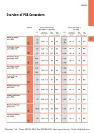
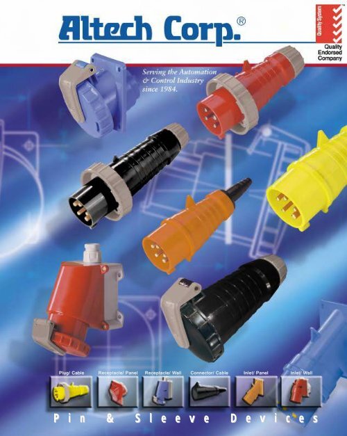
Plug/ Cable<br />
Receptacle/ Panel<br />
Receptacle/ WallW<br />
Connector/ Cable<br />
Inlet/ Panel<br />
Inlet/ WallW<br />
P i n & S l e e v e D e v i c e s
PIN & SLEEVE DEVICES<br />
line of industrial plugs and sockets are<br />
manufactured by ABL Sursum, a company well known in<br />
Europe for its quality electrical products. This major<br />
manufacturer combines the elements of good design, high<br />
quality, safety, ease of installation and competitive cost. The<br />
pin and sleeve devices are manufactured to EN 60309 Part 1<br />
and 2: IEC 60309. Their rugged construction in polyamide 6<br />
material provides good anti-tracking properties and high<br />
resistance to aggressive industrial use.<br />
In accordance with the Standard's requirements, these devices<br />
are color coded to provide positive voltage and frequency<br />
matching and external key-ways ensure correct alignment of<br />
contact pins. The position of the ground pin relative to the<br />
socket's key-way are designated as a clock hour position.<br />
The ground terminal also has a larger diameter than the<br />
contacts, making it impossible to install it in an IEC 60309<br />
device with a different voltage rating.<br />
The shrouded housing made of high impact nylon material<br />
protects the contacts from physical abuse and safeguards<br />
against touching live parts when partially engaged.<br />
All terminals are clearly marked in both IEC 309 and North<br />
American Standards.<br />
ABL 17 features include:<br />
• High Impact and Abrasion Resistance<br />
• Resistant to oil, petrol, most acids<br />
and alkalines<br />
• Temperature Range -30°C to 140°C<br />
• Electrical Rating up to 125A/500V<br />
• Excellent Anti-Tracking<br />
• Bichromate Coated Screws<br />
• All screws captive<br />
• Grooved body improves hand grip<br />
• Insulated Cable Clamp device<br />
• Maximum wiring space<br />
• Hinged Cable Clamp for easy wiring<br />
• Terminals clearly marked<br />
• All screws are accessible from one side<br />
• Back housing is ribbed to enhance hand<br />
grip.<br />
• Retaining catch is used to hold engaged<br />
devices together.<br />
• Cable gland assembly seals cable entry<br />
and provides extra strain relief reducing<br />
stress on internal components.<br />
IP44<br />
IP67<br />
Phone: 800.894.0412 - Fax: 888.723.4773 - Web: www.clrwtr.com - Email: info@clrwtr.com
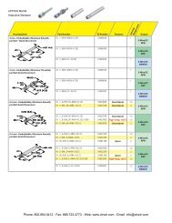
<strong>Pin</strong> and <strong>Sleeve</strong> <strong>Devices</strong> Ordering Information - Splashproof IP 44<br />
Plug Receptacle Connector Inlet<br />
<strong>Sleeve</strong> Gland Straight Angled 80°/Box <strong>Sleeve</strong> Gland Straight Angled 80°/Box<br />
Ground IP44<br />
<strong>Pin</strong> Poles Amps Voltage Color<br />
4h 2P/3W 20 125 YELLOW S31.10A S31.11A F31.13A F31.10A D31.10 K31.10A K31.11A A31.14A --- G31.10<br />
6h 2P/3W 20 250 BLUE S31.20A S31.21A F31.23A F31.20A D31.20 K31.20A K31.21A A31.24A --- G31.20<br />
7h 2P/3W 20 480 RED S31.50A S31.51A F31.53A F31.50A --- K31.50A K31.51A A31.54A --- ---<br />
12h 3P/4W 20 125/250 ORANGE S41.60A S41.61A F41.63A F41.60A --- K41.60A K41.61A A41.64A --- ---<br />
9h 3P/4W 20 250 BLUE S41.20A S41.21A F41.23A F41.20A D41.20 K41.20A K41.21A A41.24A --- G41.20<br />
7h 3P/4W 20 480 RED S41.50A S41.51A F41.53A F41.50A D41.50A* K41.50A K41.51A A41.54A --- G41.50A*<br />
7h 3P/4W 20 500 BLACK S41.50 S41.51 F41.53 F41.50 D41.50 K41.50 K41.51 A41.54 --- G41.50<br />
9h 4P/5W 20 120/208 BLUE S51.20A S51.21A F51.23A F51.20A D51.20 K51.20A K51.21A A 51.24A A51.20A G51.20<br />
7h 4P/5W 20 277/480 RED S51.50A S51.51A F51.53A F51.50A --- K51.50A K51.51A A51.54A A51.50A G51.50A*<br />
7h 4P/5W 20 500 BLACK S51.50 S51.51 F 51.53 F51.50 --- K51.50 K51.51 A51.54 A51.50 G51.50<br />
4h 2P/3W 30 125 YELLOW S32.10A S32.11A F32.13A F32.10A D32.10 K32.10A K32.11A A32.14A --- G32.10<br />
6h 2P/3W 30 250 BLUE S32.20A S32.21A F32.23A F32.20A D32.20 K32.20A K32.21A A32.24A --- G32.20<br />
7h 2P/3W 30 480 RED S32.50A S32.51A F32.53A F32.50A --- K32.50A K32.51A A32.54A --- ---<br />
12h 3P/4W 30 125/250 ORANGE S42.60A S42.61A F42.63A F42.60A --- K42.60A K42.61A A42.64A --- ---<br />
9h 3P/4W 30 250 BLUE S42.20A S42.21A F42.23A F42.20A D42.20 K42.20A K42.21A A42.24A --- G42.20<br />
7h 3P/4W 30 480 RED S42.50A S42.51A F42.53A F42.50A --- K42.50A K42.51A A42.54A --- G42.50A*<br />
7h 3P/4W 30 500 BLACK S42.50 S42.51 F42.53 F42.50 --- K 42.50 K42.51 A42.54 --- G42.50<br />
9h 4P/5W 30 120/208 BLUE S52.20A S52.21A F52.24A F52.20A D52.20 K52.20A K52.21A A52.24A A52.20A G52.20<br />
7h 4P/5W 30 277/480 RED S52.50A S52.51A F52.54A F52.50A --- K52.50A K52.51A A52.54A A52.50A G52.50A*<br />
7h 4P/5W 30 500 BLACK S52.50 S52.51 F52.54 F52.50 --- K52.50 K52.51 A52.54 A52.50 G52.50<br />
9h 3P/4W 60 250 BLUE --- S43.21A F43.23A F43.21A D43.22 --- K43.21A A43.24A --- ---<br />
7h 3P/4W 60 480 RED --- S43.51A F43.53A F43.51A D43.52A* --- K43.51A A43.54A --- ---<br />
7h 3P/4W 60 500 BLACK --- S43.51 F43.53 F 43.51 D43.52 --- K43.51 A43.54 --- ---<br />
9h 4P/5W 60 250 BLUE --- S53.21A F53.23A F53.21A D53.22 --- K53.21A A53.24A --- ---<br />
7h 4P/5W 60 277/480 RED --- S53.51A F53.53A F53.51A --- --- K53.51A A53.54A --- ---<br />
7h 4P/5W 60 500 BLACK --- S53.51 F53.53 F53.51 --- --- K53.51 A53.54 --- ---<br />
NUMBERING SYSTEM OF TYPE NUMBERS<br />
2<br />
3ØY120/1208V<br />
50/60Hz<br />
S = Plug<br />
5 = 5 Wires<br />
1 = 16A (IEC),<br />
20A (UL/CSA)<br />
3ØY250V<br />
50/60Hz<br />
1<br />
2<br />
3<br />
2<br />
S51.21A<br />
1 2 3 . 4 5 6<br />
3P+N/5W<br />
3P/4W<br />
2P/3W<br />
250V<br />
50/60Hz<br />
3<br />
IEC<br />
480-500V:<br />
5<br />
50/60Hz<br />
UL/CSA:<br />
480V 5<br />
50/60Hz<br />
IEC: 5<br />
480-500V<br />
50/60Hz<br />
3Ø480V<br />
50/60Hz<br />
IEC:277/480-<br />
288/500V<br />
50/60Hz<br />
5 3ØY277/480V<br />
50/60Hz<br />
5<br />
5<br />
125/250V<br />
60Hz<br />
12 1<br />
10 11 2<br />
9<br />
8<br />
6<br />
3<br />
4<br />
7 6 5 3Ø125V<br />
50/60Hz<br />
2 1<br />
250V<br />
50/60Hz<br />
3<br />
3ØY250V<br />
50/60Hz<br />
3ØY250V<br />
50/60Hz<br />
3<br />
6<br />
5<br />
4<br />
A = UL/CSA Version<br />
1 = Cable gland, IP 44<br />
3 = 120/208 VAC<br />
9h<br />
Blue (color)<br />
1 <strong>Pin</strong> & <strong>Sleeve</strong> Type<br />
A - Inlet, Panel mount<br />
D - Receptacles, Wall mount<br />
F - Receptacles, Panel mount<br />
G - Inlet, Wall mount<br />
K - Connector<br />
S - Plug<br />
2 No. of Wires<br />
5 - 5 Wires<br />
4 - 4 Wires<br />
3 - 3 Wires<br />
3 Ampere Rating (A)<br />
UC<br />
L<br />
1 - 16 20<br />
2 - 32 30<br />
3 - 63 60<br />
4 - 125 100<br />
4 Voltage, Ground <strong>Pin</strong><br />
position and Color<br />
6 Approvals<br />
Blank - IEC Version<br />
A - UL/CSA Version<br />
* - not UL/CSA approved<br />
5 Housing Specification<br />
A - Inlet,Panel mount<br />
0 - 45° Panel mount, IP 44<br />
4 - Panel mount, IP 44<br />
5 - 45° Panel mount, IP 67<br />
D - Receptacles, Wall mount<br />
0 - 15° Wall mount IP 44<br />
1 - 25° Wall mount with back box, IP 44<br />
(mounting holes outside)<br />
2 - 25° Wall mount with back box, IP 44<br />
(mounting holes in box)<br />
6 - 25° Wall mount with back box, IP 67<br />
(mounting holes in box)<br />
7 - 25° Wall mount with back box, IP 67<br />
(mounting holes in box)<br />
F - Receptacles, Panel mount<br />
0 - 25° panel mount, IP 44<br />
1 - 20° panel mount, IP 44<br />
3 - Panel mount, IP 44<br />
4 - Large flange, panel mount, IP 44<br />
5 - 25° panel mount, IP 67<br />
6 - 20° panel mount, IP 67<br />
7 - 15° panel mount, IP 67<br />
8 - Panel mount, IP 67<br />
9 - Panel mount with short flange, IP 67<br />
G - Inlet, Wall mount<br />
1 - 15° Wall mount, IP 44<br />
5 - 20/25° Wall mount, IP 67<br />
K - Connector<br />
0 - Cable flexible sleeve, IP 44<br />
1 - Cable gland, IP 44<br />
5 - Cable gland, IP 67<br />
S - Plug<br />
0 - Cable flexible sleeve, IP 44<br />
1 - Cable gland, IP 44<br />
5 - Cable gland, IP 67
<strong>Pin</strong> and <strong>Sleeve</strong> <strong>Devices</strong> Ordering Information - Watertight IP 67<br />
Plug Receptacle Connector Inlet<br />
Gland Straight Angled 80°/Box Gland Angled 80°/Box<br />
Ground IP67<br />
<strong>Pin</strong> Poles Amps Voltage Color<br />
4h 2P/3W 20 125 YELLOW S31.15A F31.18A F31.15A D 31.17 K31.15A --- ---<br />
6h 2P/3W 20 250 BLUE S31.25A F31.28A F31.25A D 31.27 K31.25A --- ---<br />
7h 2P/3W 20 480 RED S31.55A F31.58A F31.55A --- K31.55A --- ---<br />
12h 3P/4W 20 125/250 ORANGE S41.65A F41.68A F41.65A D 41.67 K41.65A --- ---<br />
9h 3P/4W 20 250 BLUE S41.25A F41.28A --- D 41.27 K41.25A --- ---<br />
7h 3P/4W 20 480 RED S41.55A F41.58A --- D 41.57 A K41.55A --- ---<br />
7h 3P/4W 20 500 BLACK S 41.55 F 41.58 --- D 41.57 K 41.55 --- ---<br />
9h 4P/5W 20 120/208 BLUE S51.25A F51.28A F51.26A D 51.27 K51.25A A51.25A ---<br />
7h 4P/5W 20 277/480 RED S51.55A F51.58A F51.56A --- K51.55A A51.55A ---<br />
7h 4P/5W 20 500 BLACK S 51.55 F 51.58 F 51.56 --- K 51.55 A 51.55 ---<br />
4h 2P/3W 30 125 YELLOW S32.15A F32.18A --- D 32.17 K32.15A --- ---<br />
6h 2P/3W 30 250 BLUE S32.25A F32.28A --- D 32.27 K32.25A --- ---<br />
7h 2P/3W 30 480 RED S32.55A F32.58A --- --- K32.55A --- ---<br />
12h 3P/4W 30 125/250 ORANGE S42.65A F32.68A --- --- K32.65A --- ---<br />
9h 3P/4W 30 250 BLUE S42.25A F42.28A --- D 42.27 K42.25A --- ---<br />
7h 3P/4W 30 480 RED S42.55A F42.58A --- D 42.57A K42.55A --- ---<br />
7h 3P/4W 30 500 BLACK S 42.55 F 42.58 --- D42.57 K42.55 --- ---<br />
9h 4P/5W 30 120/208 BLUE S52.25A F52.28A F52.26A D52.27 K52.25A A52.25A ---<br />
7h 4P/5W 30 277/480 RED S52.55A F52.58A F52.56A --- K52.55A A52.55A ---<br />
7h 4P/5W 30 500 BLACK S52.55 F 52.58 F 52.56 --- K 52.55 A 52.55 ---<br />
9h 3P/4W 60 250 BLUE S43.25A --- F43.26A D 43.27 K43.25A --- G 43.25<br />
7h 3P/4W 60 480 RED S43.55A --- F43.56A D 43.57A K43.55A --- G 43.55A<br />
7h 3P/4W 60 500 BLACK S 43.55 --- F 43.56 D 43.57 K 43.55 --- G 43.55<br />
9h 4P/5W 60 120/208 BLUE S53.25A F 53.28A F53.26A D 53.27 K53.25A A53.25A G 53.25<br />
7h 4P/5W 60 277/480 RED S53.55A F 53.58A F53.56A --- K53.55A A53.55A ---<br />
7h 4P/5W 60 500 BLACK S 53.55 --- F 53.56 --- K 53.55 A 53.55 ---<br />
12h 3P/4W 100 125/250 ORANGE S44.65A --- F44.67A --- K44.65A --- ---<br />
9h 3P/4W 100 250 BLUE S44.25A --- F44.27A D 44.27 K44.25A --- ---<br />
7h 3P/4W 100 480 RED S44.55A --- F44.57A D 44.57A K44.55A --- ---<br />
7h 3P/4W 100 500 BLACK S 44.55 --- F 44.57 D 44.57 K 44.55 --- ---<br />
9h 4P/5W 100 120/208 BLUE S54.25A --- F54.27A D 54.27 K54.25A --- G 54.25<br />
7h 4P/5W 100 277/480 RED S54.55A --- F54.57A --- K54.55A --- ---<br />
7h 4P/5W 100 500 BLACK S 54.55 --- F 54.57 --- K 54.55 --- ---<br />
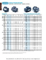
COLOR CODING AND GROUND PIN POSITIONS<br />
<strong>Pin</strong> and <strong>Sleeve</strong> devices are color coded to provide positive voltage and<br />
frequency matching and external key-ways ensure correct alignment of contact<br />
pins. The position of the ground pin relative to the socket's key-way are<br />
designated as a clock hour position.<br />
The ground terminal also has a larger diameter than the contacts, making it<br />
impossible to install in an IEC 60309 device with a different voltage rating.<br />
L1<br />
L2 L3<br />
L2<br />
PE<br />
L1<br />
N<br />
L3<br />
PE<br />
N<br />
6h<br />
9h<br />
Front view of receptacle/connector to contact barrier<br />
Note: Light typeface signifies 30 piece initial minimal order,<br />
however consult <strong>Altech</strong> for current status on this requirement.
Plug, Vinyl <strong>Sleeve</strong>, IP44 (S_ _._ 0A)<br />
Dimensions<br />
Wires Amp. (A) A B C D ØE ØF G<br />
5 20 62 181 144.5 128 7 17 73.5<br />
5 30 70 202 156.5 143.5 10 24 86.5<br />
4 20 56.5 172.5 136 119.5 7 17 68.5<br />
4 30 65 202 156.5 143.5 10 24 78.5<br />
3 20 48.5 161.5 125 112.5 6 15 58<br />
3 30 65 202 156.5 143.5 10 24 78.5<br />
Note: All dimensions<br />
are shown in<br />
millimeters. To<br />
convert to inches,<br />
divide by 25.4.<br />
Plug, Cable Gland, IP44 (S_ _._ 1A)<br />
Dimensions<br />
WiresAmp. (A) A B C D ØE G<br />
5 20 62 156 119.5 128 17 73.5<br />
5 30 70 175.5 130 143.5 21.5 86.5<br />
5 60 102 271 204.5 235 38 99.5<br />
4 20 56.5 147.5 111 119.5 17 68.5<br />
4 30 65 175.5 124 143.5 21.5 78.5<br />
4 60 102 271 204.5 235 38 99.5<br />
3 20 48.5 135 98.5 112.5 15 58<br />
3 30 65 175.5 124 143.5 21.5 78.5<br />
Note: All dimensions<br />
are shown in<br />
millimeters. To<br />
convert to inches,<br />
divide by 25.4.<br />
Receptacle, Panel Mount, Angled, IP44, (F_ _._ 0A)<br />
Dimensions<br />
WiresAmp. (A) A B C D E F G H I K L L1 M<br />
5 20 100 92 32 85 77 5.1 6 89.5 98 47 70 85 5<br />
5 30 102.5 92 44 85 77 5.1 6 100 100 47 80 95 -<br />
4 20 100 92 29 85 77 5.1 6 82.5 97 47 60 75 2.5<br />
4 30 102.5 92 39 85 77 5.1 6 94.5 97 53 65 85 -<br />
3 20 74 64 40 60 52 5.1 5 74 71.5 35 55 65 -<br />
3 30 102.5 92 39 85 77 5.1 6 94.5 97 53 65 85 -<br />
Note: All dimensions are shown in millimeters. To convert to inches, divide by 25.4.<br />
Receptacle, Panel Mount, Angled, IP44, (F_ _._ 1A)<br />
Dimensions<br />
WiresAmp. (A) A B C D E F G H I K L L1<br />
5 60 100 92 70 85 77 5.5 6 103.5 123 77 80 93<br />
4 60 100 92 70 85 77 5.5 6 103.5 123 77 80 93<br />
Note: All dimensions are shown in millimeters. To convert to inches, divide by 25.4.<br />
Receptacle, Panel Mount, Straight, IP44, (F_ _._ 3A)<br />
Dimensions<br />
WiresAmp. (A) A B C D E F G H K L<br />
5 20 72 65 52 52 52 5.5 6.5 89.5 21 50<br />
5 30 86 76 66.5 60 60 5.5 6.5 100.5 16.5 67<br />
5 60 107 107 93.5 85 77 5.5 13.5 117 38 80<br />
4 20 75 75 56 60 60 5.5 6.5 87.5 16.5 56<br />
4 30 75 75 66.5 60 60 5.5 6.5 92.5 19 65<br />
4 60 107 107 93.5 85 77 5.5 13.5 117 38 80<br />
3 20 62 62 47.5 47 47 5.5 4.5 76.5 22 45<br />
3 30 75 75 66.5 60 60 5.5 6.5 92.5 19 65<br />
Note: All dimensions are shown in millimeters. To convert to inches, divide by 25.4.
Receptacle, Panel Mount, Straight, IP44, (F_ _._ 4A)<br />
Dimensions<br />
WiresAmp. (A) A B C D E F G H K ØL<br />
5 30 75 75 65.5 60 60 5.5 6.5 102 17 58<br />
Note: All dimensions are shown in millimeters. To convert to inches, divide by 25.4.<br />
Receptacle, Wall Mount, Angled/Box, IP44, (D_ _._ 0)<br />
Dimensions<br />
WiresAmp. (A) A B C D E F G H Pg<br />
5 16 90 96 107 35 85 5 9 133 1xM20<br />
5 32 92.5 106 116.5 35 93 5 9 147 1xM25<br />
4 16 82.5 86 100.5 35 75 5 9 125 1xM20<br />
4 32 92.5 106 115 35 93 5 9 141 1xM25<br />
3 16 82.5 86 97 35 75 5 9 123 1xM20<br />
3 32 92.5 106 105 35 93 5 9 141 1xM25<br />
Note: All dimensions are shown in millimeters. To convert to inches, divide by 25.4.<br />
Receptacle, Wall Mount, Angled/Box, IP44, (D_ _._ 2)<br />
Dimensions<br />
Wires Amp. A B C C1 D E F G H I Pg<br />
5 63 170 118 170 102 6 6 212 130 3xM32<br />
4 63 170 118 170 102 6 6 212 130 3xM32<br />
Note: All dimensions are shown in millimeters. To convert to inches, divide by 25.4.<br />
Connector, Vinyl <strong>Sleeve</strong>, IP44, (K_ _._ 0A)<br />
Dimensions<br />
WiresAmp. (A) A B C ØD ØE<br />
5 20 64 193 89.5 7 17<br />
5 30 72 215.5 100 10 24<br />
4 20 56.5 184.5 82.5 7 17<br />
4 30 66 215.5 94.5 10 24<br />
3 20 49.5 170.5 74 6 15<br />
3 30 66 215.5 94.5 10 24<br />
Note: All dimensions are shown in millimeters. To convert to inches,<br />
divide by 25.4.<br />
Phone: 800.894.0412 - Fax: 888.723.4773 - Web: www.clrwtr.com - Email: info@clrwtr.com
Connector, Cable Gland, IP44, (K_ _._ 1A)<br />
Dimensions<br />
WiresAmp. (A) A B C ØD<br />
5 20 64 168 89.5 17<br />
5 30 72 189 100 21.5<br />
5 60 80 283.5 103.5 38<br />
4 20 56.5 159.5 82.5 17<br />
4 30 66 189 94.5 21.5<br />
4 60 80 283.5 103.5 38<br />
3 20 49.5 144 74 15<br />
3 30 66 189 94.5 21.5<br />
Note: All dimensions are<br />
shown in millimeters.<br />
To convert to inches,<br />
divide by 25.4.<br />
Inlet, Panel Mount, Straight, IP44, (A_ _._ 4A)<br />
Dimensions<br />
WiresAmp. (A) A B C D E F G H ØK<br />
5 20 75 75 44 60 60 5.5 6.5 21.5 70<br />
5 30 85 75 53 60 60 5.5 6.5 23.5 70<br />
5 60 107 107 81.5 85 77 5.5 13.5 38 80<br />
4 20 75 75 44 60 60 5.5 6.5 24.5 70<br />
4 30 75 75 53 60 60 5.5 6.5 27.5 70<br />
4 60 107 107 81.5 85 77 5.5 13.5 38 80<br />
3 20 62 62 44 47 47 5.5 4.5 21.5 50<br />
3 30 75 75 53 60 60 5.5 6.5 27.5 70<br />
Note: All dimensions are shown in millimeters. To convert to inches, divide by 25.4.<br />
Inlet, Panel Mount, Angled, IP44, (A_ _._ 0A)<br />
Dimensions<br />
WiresAmp. (A) A B C D E F G H<br />
5 20 85 85 100 70 70 6.2 6 141<br />
5 32 85 85 115 70 70 6 6 158<br />
Note: All dimensions are shown in millimeters. To convert to inches,<br />
divide by 25.4.<br />
Inlet, Wall Mount, 80°/Box, IP44, (G_ _._ 0A)<br />
M<br />
Dimensions<br />
WiresAmp. (A) A B C D E F G H Pg<br />
M<br />
5 16 112 80 110 10.5 60 5 4 145 2xM20<br />
5 32 125 90 131 10 68 5.3 4 165 3xM25<br />
4 16 112 80 104 10.5 60 5 4 143 2xM20<br />
4 32 125 90 124 10 68 5.3 4 164 3xM25<br />
3 16 90 68 96 10.5 48 4.5 4 122 2xM20<br />
3 32 125 90 124 10 68 5.3 4 164 3xM25<br />
Note: All dimensions are shown in millimeters. To convert to inches, divide by 25.4.
Plug, Cable Gland, IP67 (S_ _._ 5A)<br />
Dimensions<br />
WiresAmp. (A) A B C D E<br />
5 20 85 156 119.5 128 17<br />
5 30 98 175.5 130 143.5 21.5<br />
5 60 113.5 271 204.5 235 38<br />
5 100 131 311 236 268.5 44<br />
4 20 77 147.5 111 119.5 17<br />
4 30 91 175.5 124 143.5 21.5<br />
4 60 113.5 271 204.5 235 38<br />
4 100 131 311 236 268.5 44<br />
3 20 69 135 98.5 112.5 15<br />
3 30 91 175.5 124 143.5 21.5<br />
Note: All dimensions are shown in millimeters. To convert to inches,<br />
divide by 25.4.<br />
Receptacle, Panel Mount, Angled, IP67, (F_ _._ 5A)<br />
Dimensions<br />
WiresAmp. (A) A B C D E F G H K L L1<br />
3 20 74 64 49 60 52 5.1 5 82 39 55 65<br />
4 20 ? ? ? ? ? ? ? ? ? ? ?<br />
Note: All dimensions are shown in millimeters. To convert to inches, divide by 25.4.<br />
Receptacle, Panel Mount, Angled, IP67, (F_ _._ 6A)<br />
Dimensions<br />
WiresAmp. (A) A B C D E F G H K L L1<br />
5 20 100 92 50 85 77 5.1 6 100 38 70 80<br />
5 30 102.5 92 60 85 77 5.1 6 115 39 80 95<br />
5 60 100 92 70 85 77 5.5 6 123 77 80 93<br />
4 60 100 92 70 85 77 5.5 6 123 77 80 93<br />
Note: All dimensions are shown in millimeters. To convert to inches, divide by 25.4.<br />
Receptacle, Panel Mount, Angled, IP67, (F_ _._ 7A)<br />
Dimensions<br />
WiresAmp. (A) A B C D E F G H I K L L1 M<br />
5 100 114 110 82 90 90 6.3 5 141 91 92 92 115 9<br />
4 100 114 110 82 90 90 6.3 5 141 91 92 92 115 9<br />
Note: All dimensions are shown in millimeters. To convert to inches, divide by 25.4.
Receptacle, Panel Mount, Straight, IP67, (D_ _._ 8A)<br />
B<br />
A<br />
D<br />
F<br />
E<br />
K<br />
C<br />
G<br />
H<br />
Dimensions<br />
WiresAmp. (A) A B C D E F G H K L<br />
5 20 72 65 52 52 52 5.5 6.5 89.5 21 50<br />
5 30 86 76 66.5 60 60 5.5 6.5 100.5 16.5 67<br />
5 60 107 107 93.5 85 77 5.5 13.5 117 38 80<br />
4 20 75 75 56 60 60 5.5 6.5 87.5 16.5 56<br />
4 30 75 75 66.5 60 60 5.5 6.5 92.5 19 65<br />
4 60 107 107 93.5 85 77 5.5 13.5 117 38 80<br />
3 20 62 62 47.5 47 47 5.5 4.5 76.5 22 45<br />
3 30 75 75 66.5 60 60 5.5 6.5 92.5 19 65<br />
Note: All dimensions are shown in millimeters. To convert to inches, divide by 25.4.<br />
L<br />
Receptacle, Wall Mount, 80°/Box, IP67, (D_ _._ 7A)<br />
Dimensions<br />
WiresAmp. (A) A B C D D1 E E1 ØF F1 F2 G H I K α Pg<br />
5 16 125 90 139 10 – 68 – 5.3 – – 4 167 – – 25° 3xM25<br />
5 32 125 90 156 10 – 68 – 5.3 – – 4 178 – – 25° 3xM25<br />
5 63 170 118 177 – – – – 6 – – 6 213 102 130 25° 3xM32<br />
5 125 260 165 213 – – – – 8.1 – – 9 296 141 210 20° 2xM40<br />
4 16 125 90 132 10 – 68 – 5.3 – – 4 169 – – 25° 3xM25<br />
4 32 125 90 150 10 – 68 – 5.3 – – 4 176 – – 25° 3xM25<br />
4 63 170 118 177 – – – – 6 – – 6 213 102 130 25° 3xM25<br />
4 125 260 165 213 – – – – 8.1 – – 9 296 141 210 20° 2xM40<br />
3 16 90 68 115 – 10.5 – 48 – 6 4.5 4 135 – – 25° 2xM20<br />
3 32 125 90 150 10 – 68 – 5.3 – – 4 176 – – 25° 3xM25<br />
Note: All dimensions are shown in millimeters. To convert to inches, divide by 25.4.<br />
Connector, Cable Gland, IP67, (K_ _._ 5A)<br />
Dimensions<br />
WiresAmp. (A) A B C ØD<br />
5 20 85 172 97 17<br />
5 30 98 193.5 112 21.5<br />
5 60 103 289 115 38<br />
5 100 121 333.5 136 44<br />
4 20 77 163 89 17<br />
4 30 91 192.5 105 21.5<br />
4 60 103 289 115 38<br />
4 100 121 333.5 136 44<br />
3 20 69 151.5 81 15<br />
3 30 91 192.5 105 21.5<br />
Note: All dimensions are<br />
shown in millimeters.<br />
To convert to inches, divide<br />
by 25.4.<br />
Inlet, Panel Mount, Angled, IP67, (A_ _._ 5A)<br />
Dimensions<br />
WiresAmp. (A) A B C D E F G H<br />
5 20 85 85 100 70 70 6.2 6 141<br />
5 30 85 85 115 70 70 6 6 158<br />
5 60 114 114 158 90 90 6.5 6 213<br />
Note: All dimensions are shown in millimeters. To convert to inches,<br />
divide by 25.4.<br />
Inlet, Wall Mount, 80°/Box, IP67, (G_ _._ 5)<br />
M<br />
Dimensions<br />
WiresAmp. (A) A B C D E F G H α Pg<br />
M<br />
5 63 170 118 177 130 102 6 6 251 25° 3xM32<br />
5 125 260 165 207 210 141 8.1 9 350 20° 2xM40<br />
4 63 170 118 177 130 102 6 6 251 25° 3xM32<br />
Note: All dimensions are shown in millimeters. To convert to inches, divide by 25.4.
TECHNICAL DATA A & ACCESSORIESA<br />
Electrical<br />
Insulation Voltage, Max.<br />
(Volts)<br />
Dielectric Withstanding<br />
Voltage<br />
Current<br />
Interrupting<br />
Temperature<br />
Rise<br />
Endurance, Connect and<br />
disconnect cycles at full<br />
rated current and voltage<br />
Mechanical<br />
Cord Accommodation,<br />
Min.<br />
Impact Resistance<br />
Cord Grip<br />
Cable Retention, Min.<br />
Terminal Identification<br />
Environmental<br />
Temperature Range,<br />
Operating<br />
Moisture Resistance<br />
Flammability<br />
16/20 Amp. (A) = 750V 63/60 Amp. (A) = 750V<br />
32/30 Amp. (A) = 750V 125/100 Amp. (A) = 750V<br />
All 2P/3W devices: 16/20Amp(A) and 32/30Amp(A) = 500V<br />
16/20 Amp. (A) = 2,500V 63/60 Amp. (A) = 2,500 V<br />
32/30 Amp. (A) = 2,500V 125/100 Amp. (A) = 2,500V<br />
Per IEC 60309-1<br />
Certified for current interrupting at 100% (UL)/110% (IEC) of the rated operating voltage and 125%<br />
(IEC)/150% (UL) of the rated current at a power factor of 0.6 (16/20 Amp. (A), 32/30 Amp. (A),<br />
63/60 Amp. (A)) and 0.7 (125/100 Amp. (A))<br />
Maximum 30°C temperature rise at full rated current<br />
16/20 Amp. (A) = 5,000 @ a p.f. of 0.6 63/60 Amp. (A) = 1,000 @ a p.f. of 0.6<br />
32/30 Amp. (A) = 5,000 @ a p.f. of 0.6 125/100 Amp. (A) = 1,000 @ a p.f. of 0.7<br />
Round portable service cords of diameters commensurate with the device as defined in UL<br />
Standard 62, CSA C22.2 No. 49 and the harmonized European Standards. Per IEC 60309-<br />
1, Table X<br />
Per IEC 60309-1, Clause 24; CSA C22.2<br />
Per IEC 60309-1<br />
Table XI<br />
Per IEC 60309-1, Sub-clause 7.5 and UL 1682, 1686<br />
-25°C to + 80°C (-13°F to + 176°F)<br />
Splashproof IP 44; Watertight IP 67; Per IEC 60309-1, Clause 18 and IEC 60529<br />
Self-extinguishing Per IEC 60309-1, Clause 27<br />
Flame Class Rating UL 94V-2<br />
Material<br />
Housing (Front and Back)<br />
Cover<br />
Cover Rivet<br />
Cover Spring<br />
Contact Carrier<br />
Contacts<br />
Terminal Screws<br />
Internal Strain Relief<br />
External Strain Relief<br />
Grommet<br />
Retaining Ring<br />
Assembly Screws<br />
Type 6 Nylon (UL 94V-2)<br />
Type 6 Nylon (UL 94V-2)<br />
Brass<br />
Stainless Steel (A2)<br />
Type 6 Nylon (UL 94V-2)<br />
Brass<br />
Steel, Nickel Plated, bichromated<br />
Type 6 Nylon (UL 94V-2)<br />
Type 6 Nylon (UL 94V-2)<br />
Concentric Laminated Rubber<br />
Steel, Electro Zinc Plated<br />
Steel, Nickel Plated, chromated<br />
Recommended wire size<br />
IEC<br />
Amp Rating Minimum Wire Size per IEC<br />
16 1.5mm 2<br />
32 4mm 2<br />
63 10mm 2<br />
125 35mm 2<br />
Twist Nipple IP 54<br />
Material Type cable diameter<br />
High pressure M20 6 - 14mm<br />
polyethylene M25 7 - 17mm<br />
M32 9 - 24mm<br />
PA - Cable Gland IP 67<br />
Material Type cable diameter<br />
glass fibre M20 7 - 14mm<br />
reinforced M25 9 - 18mm<br />
polyamide M32 14 - 25mm<br />
grey RAL 7035 M40 18 - 32mm<br />
Recommended wire size<br />
UL/CSA<br />
Amp Rating AWG for 100% of Rating*<br />
20 14 AWG<br />
30 8 AWG<br />
60 4 AWG<br />
100 2 AWG<br />
Recommended screw torque for<br />
terminal set screws<br />
Wire Size Nm. ft. / lb in. / lb<br />
1.5mm 2 / 14 AWG 0.8 0.6 7.1<br />
4mm 2 / 8 AWG 1.2 0.9 10.6<br />
10mm 2 / 4 AWG 2.0 1.5 17.7<br />
35mm 2 / 2 AWG 10.0 7.4 88.5<br />
* Please refer to National Electric Code, to determine<br />
wire size for different Amp Ratings.