ABB Miniature Circuit Breakers Catalog
ABB Miniature Circuit Breakers Catalog
ABB Miniature Circuit Breakers Catalog

Create successful ePaper yourself
Turn your PDF publications into a flip-book with our unique Google optimized e-Paper software.
<strong>Miniature</strong> circuit breakers<br />
Index<br />
<strong>Miniature</strong> circuit<br />
breakers<br />
15 - <strong>Miniature</strong> circuit breakers<br />
S200 <strong>Miniature</strong> circuit breakers...............................15.1 - 15.42<br />
UL 489 Series<br />
Ordering details<br />
Description...............................................................................................................15.1<br />
Features...................................................................................................................15.1<br />
S200U-K, 240 VAC..................................................................................................15.2<br />
S200U-Z, 240 VAC..................................................................................................15.3<br />
S200UP-K, 480Y/277 VAC......................................................................................15.4<br />
S200UP-Z, 480Y/277 VAC.......................................................................................15.5<br />
SU200PR-K, 480Y/277 VAC....................................................................................15.6<br />
S200UDC-K, 1 pole 60 VDC, 2 pole 125 VDC.........................................................15.7<br />
S200UDC-Z, 1 pole 60 VDC, 2 pole 125 VDC..........................................................15.8<br />
Accessories..........................................................................................................15.9 - 15.12<br />
Technical data.....................................................................................................15.13 - 15.15<br />
Dimensions.....................................................................................................................15.16<br />
UL 1077 Series<br />
Ordering details<br />
Description & features............................................................................................15.17<br />
S200-B, 480Y/277 VAC.........................................................................................15.18<br />
S200-C, 480Y/277 VAC........................................................................................15.19<br />
S200-D, 480Y/277 VAC.........................................................................................15.20<br />
S200-K, 480Y/277 VAC.........................................................................................15.21<br />
S200-Z, 480Y/277 VAC.........................................................................................15.22<br />
S200P-B, 480Y/277 VAC.......................................................................................15.23<br />
S200P-C, 480Y/277 VAC.......................................................................................15.24<br />
S200P-D, 480Y/277 VAC.......................................................................................15.25<br />
S200P-K, 480Y/277 VAC.......................................................................................15.26<br />
S200P-Z, 480Y/277 VAC.......................................................................................15.27<br />
S200PR-K, 240 VAC, Ring tongue.........................................................................15.28<br />
S280UC-K, 500 VDC.............................................................................................15.29<br />
S280UC-Z, 500 VDC.............................................................................................15.30<br />
Accessories........................................................................................................15.31 - 15.39<br />
Technical data.....................................................................................................15.40 - 15.42<br />
Dimensions.........................................................................................................15.43 - 15.44<br />
Application guide...................................................15.45 - 15.52<br />
Introduction, overload, short circuit, breaker definition.....................................................15.45<br />
<strong>Circuit</strong> breaker construction................................................................................15.46 - 15.47<br />
<strong>Circuit</strong> breaker current limitation..........................................................................15.48 - 15.49<br />
Selective coordination and series ratings.............................................................15.50 - 15.51<br />
<strong>Miniature</strong> circuit breaker cutaway....................................................................................15.52<br />
S800 <strong>Miniature</strong> circuit breakers.............................15.53 - 15.80<br />
UL 489 Series<br />
Ordering details<br />
Description & features............................................................................................15.53<br />
S800U-K, 240 VAC................................................................................................15.54<br />
S800U-Z, 240 VAC................................................................................................15.55<br />
S803W-SCL-SR UL Short circuit current limiter..........................................15.56 - 15.57<br />
S800W-RSU Remote sensing unit.........................................................................15.58<br />
IEC Series<br />
Ordering details<br />
Description & features............................................................................................15.59<br />
S800S-B, 690 VAC................................................................................................15.60<br />
S800S-C, 690 VAC................................................................................................15.61<br />
S800S-D, 690 VAC................................................................................................15.62<br />
S800S-K, 690 VAC................................................................................................15.63<br />
UL & IEC Series<br />
Accessories........................................................................................................15.64 - 15.65<br />
Technical data.....................................................................................................15.67 - 15.78<br />
Dimensions.....................................................................................................................15.79<br />
S500 <strong>Miniature</strong> circuit breakers.............................15.81 - 15.87<br />
Ordering details<br />
Description & features............................................................................................15.81<br />
S500-K, UL 600Y/277 VAC / IEC 690 VAC............................................................15.82<br />
S500UC-B, 250 VDC per pole (600 VDC 4P).........................................................15.83<br />
S500UC-K, 250 VDC per pole (600 VDC 4P).........................................................15.84<br />
Accessories....................................................................................................................15.85<br />
Technical data.................................................................................................................15.86<br />
Dimensions.....................................................................................................................15.87<br />
Technical data.........................................................15.89 - 15.97<br />
15<br />
Phone: 800.894.0412 - Fax: 888.723.4773 - Web: www.clrwtr.com - Email: info@clrwtr.com
S200<br />
UL 489 Series<br />
<strong>Miniature</strong><br />
circuit breakers<br />
S200<br />
S200 UL 489 Series<br />
<strong>Miniature</strong> circuit breakers<br />
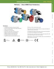
Description<br />
The S200 Series miniature circuit breaker offers<br />
a compact solution for protection requirements.<br />
The S200U AND S200UP devices are UL 489<br />
tested current limiting and DIN rail mounted.<br />
The S200U and S200UP is available with<br />
application-specific trip characteristics to<br />
provide maximum circuit protection.<br />
The breakers offer thermal-magnetic trip<br />
protection according to K and Z characteristics.<br />
For the worldwide market, the breakers carry<br />
UL, CSA, IEC, CE and many other agency<br />
approvals and certifications.<br />
Features<br />
• UL current limiting<br />
• Fast breaking time (2.3 – 2.5 ms)<br />
• Bus connection system<br />
• Wide range of accessories<br />
• Available with variable depth handle<br />
mechanism<br />
• CE certified and marked<br />
• DIN rail mounting<br />
• Finger safe terminals<br />
• Multi-function terminals<br />
• Suitable for reverse feed but S200UDC has<br />
polarity<br />
• UL 489 Listed - branch circuit protective<br />
device. UL File #E212323<br />
S200U S200UP SU200PR S200UDC<br />
Amperage 0.2 – 63 0.2 – 25 0.2 – 35A ; 40 – 63A 1 – 63<br />
Voltage 240 VAC 480Y/277VAC 480Y/277 VAC ; 240 VAC 60-125 VDC<br />
Poles 1, 2, 3, 4 1, 2, 3, 4 1, 2, 3, 4 1, 2<br />
Trip characteristics K, Z K, Z K K, Z<br />
Interrupting ratings<br />
Up to 25 kA : IEC 60947-2<br />
10 kA : UL 489<br />
10 kA : CSA 22.2 No. 5<br />
Up to 25 kA : IEC<br />
60947-2<br />
10 kA : UL 489<br />
10 kA : CSA 22.2 No. 5<br />
10kA: UL489<br />
10kA: CSA 22.2 No.5<br />
Auxiliary contacts Yes Yes Yes Yes<br />
Bell alarm Yes Yes Yes Yes<br />
Shunt trip Yes Yes Yes Yes<br />
Bus bar Yes Yes No Yes<br />
14 kA : UL489<br />
14 kA: CSA 22.2 No. 5<br />
15<br />
Phone: 800.894.0412 - Fax: 888.723.4773 - Web: www.clrwtr.com - Email: info@clrwtr.com
<strong>Miniature</strong><br />
circuit breakers<br />
S200<br />
S200U-K, 240 VAC<br />
Branch circuit protection<br />
UL 489, CSA 22.2 No. 5<br />
15<br />
K<br />
S201U-K<br />
S202U-K<br />
No. of<br />
poles<br />
1<br />
2<br />
Rated<br />
current<br />
<strong>Catalog</strong> number<br />
No. of<br />
poles<br />
Rated<br />
current<br />
<strong>Catalog</strong> number<br />
0.2 S201U-K0.2<br />
0.2 S203U-K0.2<br />
0.3 S201U-K0.3 0.3 S203U-K0.3<br />
0.5 S201U-K0.5 0.5 S203U-K0.5<br />
0.75 S201U-K0.75 0.75 S203U-K0.75<br />
1 S201U-K1 1 S203U-K1<br />
1.6 S201U-K1.6 1.6 S203U-K1.6<br />
2 S201U-K2 2 S203U-K2<br />
3 S201U-K3 3 S203U-K3<br />
4 S201U-K4 4 S203U-K4<br />
5 S201U-K5 5 S203U-K5<br />
6 S201U-K6 6 S203U-K6<br />
8 S201U-K8 3<br />
8 S203U-K8<br />
10 S201U-K10 10 S203U-K10<br />
15 S201U-K15 15 S203U-K15<br />
16 S201U-K16 16 S203U-K16<br />
20 S201U-K20 20 S203U-K20<br />
25 S201U-K25 25 S203U-K25<br />
30 S201U-K30 30 S203U-K30<br />
32 S201U-K32 32 S203U-K32<br />
40 S201U-K40 40 S203U-K40<br />
50 S201U-K50 50 S203U-K50<br />
60 S201U-K60 60 S203U-K60<br />
63 S201U-K63 63 S203U-K63<br />
0.2 S202U-K0.2<br />
0.2 S204U-K0.2<br />
0.3 S202U-K0.3 0.3 S204U-K0.3<br />
0.5 S202U-K0.5 0.5 S204U-K0.5<br />
0.75 S202U-K0.75 0.75 S204U-K0.75<br />
1 S202U-K1 1 S204U-K1<br />
1.6 S202U-K1.6 1.6 S204U-K1.6<br />
2 S202U-K2 2 S204U-K2<br />
3 S202U-K3 3 S204U-K3<br />
4 S202U-K4 4 S204U-K4<br />
5 S202U-K5 5 S204U-K5<br />
6 S202U-K6 6 S204U-K6<br />
8 S202U-K8 8 S204U-K8<br />
4<br />
10 S202U-K10 10 S204U-K10<br />
15 S202U-K15 15 S204U-K15<br />
16 S202U-K16 16 S204U-K16<br />
20 S202U-K20 20 S204U-K20<br />
25 S202U-K25 25 S204U-K25<br />
30 S202U-K30 30 S204U-K30<br />
32 S202U-K32 32 S204U-K32<br />
40 S202U-K40 40 S204U-K40<br />
50 S202U-K50 50 S204U-K50<br />
60 S202U-K60 60 S204U-K60<br />
63 S202U-K63 63 S204U-K63<br />
Tripping characteristic K<br />
UL 489<br />
240 VAC<br />
10 kA<br />
S203U-K<br />
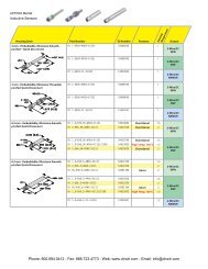
Inductive loads<br />
• K Curve<br />
• Designed for allowing higher in-rush<br />
currents during system start up<br />
• Example: motors, transformers<br />
Accessories & technical data<br />
Accessories – See page 15.9 - 15.13<br />
Technical data – See page 15.14 -15.16<br />
S204U-K<br />
Note: This breaker for AC use only<br />
Phone: 800.894.0412 - Fax: 888.723.4773 - Web: www.clrwtr.com - Email: info@clrwtr.com
S200U-Z, 240 VAC<br />
Branch circuit protection<br />
UL 489, CSA 22.2 No. 5<br />
<strong>Miniature</strong><br />
circuit breakers<br />
S200<br />
Z<br />
S201U-Z<br />
S202U-Z<br />
No. of<br />
poles<br />
1<br />
2<br />
Rated<br />
current<br />
<strong>Catalog</strong> number<br />
No. of<br />
poles<br />
Rated<br />
current<br />
<strong>Catalog</strong> number<br />
0.5 S201U-Z0.5<br />
0.5 S203U-Z0.5<br />
1 S201U-Z1 1 S203U-Z1<br />
1.6 S201U-Z1.6 1.6 S203U-Z1.6<br />
2 S201U-Z2 2 S203U-Z2<br />
3 S201U-Z3 3 S203U-Z3<br />
4 S201U-Z4 4 S203U-Z4<br />
5 S201U-Z5 5 S203U-Z5<br />
6 S201U-Z6 6 S203U-Z6<br />
8 S201U-Z8 8 S203U-Z8<br />
10 S201U-Z10 10 S203U-Z10<br />
15 S201U-Z15 3<br />
15 S203U-Z15<br />
16 S201U-Z16 16 S203U-Z16<br />
20 S201U-Z20 20 S203U-Z20<br />
25 S201U-Z25 25 S203U-Z25<br />
30 S201U-Z30 30 S203U-Z30<br />
32 S201U-Z32 32 S203U-Z32<br />
40 S201U-Z40 40 S203U-Z40<br />
50 S201U-Z50 50 S203U-Z50<br />
60 S201U-Z60 60 S203U-Z60<br />
63 S201U-Z63 63 S203U-Z63<br />
0.5 S202U-Z0.5<br />
0.5 S204U-Z0.5<br />
1 S202U-Z1 1 S204U-Z1<br />
1.6 S202U-Z1.6 1.6 S204U-Z1.6<br />
2 S202U-Z2 2 S204U-Z2<br />
3 S202U-Z3 3 S204U-Z3<br />
4 S202U-Z4 4 S204U-Z4<br />
5 S202U-Z5 5 S204U-Z5<br />
6 S202U-Z6 6 S204U-Z6<br />
8 S202U-Z8 8 S204U-Z8<br />
10 S202U-Z10 10 S204U-Z10<br />
15 S202U-Z15 4<br />
15 S204U-Z15<br />
16 S202U-Z16 16 S204U-Z16<br />
20 S202U-Z20 20 S204U-Z20<br />
25 S202U-Z25 25 S204U-Z25<br />
30 S202U-Z30 30 S204U-Z30<br />
32 S202U-Z32 32 S204U-Z32<br />
40 S202U-Z40 40 S204U-Z40<br />
50 S202U-Z50 50 S204U-Z50<br />
60 S202U-Z60 60 S204U-Z60<br />
63 S202U-Z63 63 S204U-Z63<br />
S203U-Z<br />
Tripping characteristic Z<br />
UL 489<br />
240 VAC<br />
10 kA<br />
Resistive loads<br />
• Z Curve<br />
• Designed to provide maximum protection with<br />
a very low short<br />
circuit trip setting<br />
• Example: semiconductors, control circuits<br />
Accessories & technical data<br />
Accessories – See page 15.9 - 15.13<br />
Technical data – See page 15.14 -15.16<br />
15<br />
S204U-Z<br />
Note: This breaker for AC use only<br />
Phone: 800.894.0412 - Fax: 888.723.4773 - Web: www.clrwtr.com - Email: info@clrwtr.com
<strong>Miniature</strong><br />
circuit breakers<br />
S200<br />
S200UP-K, 480Y/277 VAC<br />
Branch circuit protection<br />
UL 489, CSA 22.2 No. 5<br />
K<br />
S201UP-K<br />
No. of<br />
poles<br />
1<br />
2<br />
Rated<br />
current<br />
<strong>Catalog</strong> number<br />
No. of<br />
poles<br />
Rated<br />
current<br />
<strong>Catalog</strong> number<br />
0.2 S201UP-K0.2<br />
0.2 S203UP-K0.2<br />
0.3 S201UP-K0.3 0.3 S203UP-K0.3<br />
0.5 S201UP-K0.5 0.5 S203UP-K0.5<br />
0.75 S201UP-K0.75 0.75 S203UP-K0.75<br />
1 S201UP-K1 1 S203UP-K1<br />
1.6 S201UP-K1.6 1.6 S203UP-K1.6<br />
2 S201UP-K2 2 S203UP-K2<br />
3 S201UP-K3 3 S203UP-K3<br />
4 S201UP-K4 3<br />
4 S203UP-K4<br />
5 S201UP-K5 5 S203UP-K5<br />
6 S201UP-K6 6 S203UP-K6<br />
8 S201UP-K8 8 S203UP-K8<br />
10 S201UP-K10 10 S203UP-K10<br />
15 S201UP-K15 15 S203UP-K15<br />
16 S201UP-K16 16 S203UP-K16<br />
20 S201UP-K20 20 S203UP-K20<br />
25 S201UP-K25 25 S203UP-K25<br />
0.2 S202UP-K0.2<br />
0.2 S204UP-K0.2<br />
0.3 S202UP-K0.3 0.3 S204UP-K0.3<br />
0.5 S202UP-K0.5 0.5 S204UP-K0.5<br />
0.75 S202UP-K0.75 0.75 S204UP-K0.75<br />
1 S202UP-K1 1 S204UP-K1<br />
1.6 S202UP-K1.6 1.6 S204UP-K1.6<br />
2 S202UP-K2 2 S204UP-K2<br />
3 S202UP-K3 3 S204UP-K3<br />
4 S202UP-K4<br />
4<br />
4 S204UP-K4<br />
5 S202UP-K5 5 S204UP-K5<br />
6 S202UP-K6 6 S204UP-K6<br />
8 S202UP-K8 8 S204UP-K8<br />
10 S202UP-K10 10 S204UP-K10<br />
15 S202UP-K15 15 S204UP-K15<br />
16 S202UP-K16 16 S204UP-K16<br />
20 S202UP-K20 20 S204UP-K20<br />
25 S202UP-K25 25 S204UP-K25<br />
S202UP-K<br />
Tripping characteristic K<br />
UL 489<br />
480Y/277 VAC<br />
10 kA<br />
15<br />
Inductive loads<br />
• K Curve<br />
• Designed for allowing higher in-rush currents<br />
during system start up<br />
• Example: motors, transformers<br />
Accessories & technical data<br />
Accessories – See page 15.9 - 15.13<br />
Technical data – See page 15.14 -15.16<br />
S203UP-K<br />
S204UP-K<br />
Note: This breaker for AC use only<br />
Phone: 800.894.0412 - Fax: 888.723.4773 - Web: www.clrwtr.com - Email: info@clrwtr.com
S200UP-Z, 480Y/277 VAC<br />
Branch circuit protection<br />
UL 489, CSA 22.2 No. 5<br />
<strong>Miniature</strong><br />
circuit breakers<br />
S200<br />
Z<br />
S201UP-Z<br />
No. of<br />
poles<br />
1<br />
2<br />
Rated<br />
current<br />
<strong>Catalog</strong> number<br />
No. of<br />
poles<br />
Rated<br />
current<br />
<strong>Catalog</strong> number<br />
0.5 S201UP-Z0.5<br />
0.5 S203UP-Z0.5<br />
1 S201UP-Z1 1 S203UP-Z1<br />
1.6 S201UP-Z1.6 1.6 S203UP-Z1.6<br />
2 S201UP-Z2 2 S203UP-Z2<br />
3 S201UP-Z3 3 S203UP-Z3<br />
4 S201UP-Z4 4 S203UP-Z4<br />
5 S201UP-Z5 5 S203UP-Z5<br />
6 S201UP-Z6 3<br />
6 S203UP-Z6<br />
8 S201UP-Z8 8 S203UP-Z8<br />
10 S201UP-Z10 10 S203UP-Z10<br />
15 S201UP-Z15 15 S203UP-Z15<br />
16 S201UP-Z16 16 S203UP-Z16<br />
20 S201UP-Z20 20 S203UP-Z20<br />
25 S201UP-Z25 25 S203UP-Z25<br />
0.5 S202UP-Z0.5<br />
0.5 S204UP-Z0.5<br />
1 S202UP-Z1 1 S204UP-Z1<br />
1.6 S202UP-Z1.6 1.6 S204UP-Z1.6<br />
2 S202UP-Z2 2 S204UP-Z2<br />
3 S202UP-Z3 3 S204UP-Z3<br />
4 S202UP-Z4 4 S204UP-Z4<br />
5 S202UP-Z5 5 S204UP-Z5<br />
6 S202UP-Z6 4<br />
6 S204UP-Z6<br />
8 S202UP-Z8 8 S204UP-Z8<br />
10 S202UP-Z10 10 S204UP-Z10<br />
15 S202UP-Z15 15 S204UP-Z15<br />
16 S202UP-Z16 16 S204UP-Z16<br />
20 S202UP-Z20 20 S204UP-Z20<br />
25 S202UP-Z25 25 S204UP-Z25<br />
S202UP-Z<br />
Tripping characteristic Z<br />
UL 489<br />
480Y/277 VAC<br />
10 kA<br />
Resistive loads<br />
• Z Curve<br />
• Designed to provide maximum protection with<br />
a very low short circuit trip setting<br />
• Example: semiconductors, control circuits<br />
Accessories & technical data<br />
Accessories – See page 15.9 - 15.13<br />
Technical data – See page 15.14 -15.16<br />
15<br />
S203UP-Z<br />
S204UP-Z<br />
Note: This breaker for AC use only<br />
Phone: 800.894.0412 - Fax: 888.723.4773 - Web: www.clrwtr.com - Email: info@clrwtr.com
15<br />
<strong>Miniature</strong><br />
circuit breakers<br />
S200<br />
K<br />
SU201PR-K0.2<br />
SU202PR-K0.2<br />
SU203PR-K0.2<br />
SU200PR-K, 480Y/277 VAC, Ring tongue<br />
Branch circuit protection<br />
UL489, CSA 22.2 No.5<br />
No. of<br />
poles<br />
1<br />
2<br />
Rated<br />
current<br />
<strong>Catalog</strong> number<br />
0.2 SU201PR-K0.2<br />
No. of<br />
poles<br />
3<br />
Rated<br />
current<br />
<strong>Catalog</strong> number<br />
0.2 SU203PR-K0.2<br />
0.3 SU201PR-K0.3 0.3 SU203PR-K0.3<br />
0.5 SU201PR-K0.5 0.5 SU203PR-K0.5<br />
0.75 SU201PR-K0.75 0.75 SU203PR-K0.75<br />
1 SU201PR-K1 1 SU203PR-K1<br />
1.6 SU201PR-K1.6 1.6 SU203PR-K1.6<br />
2 SU201PR-K2 2 SU203PR-K2<br />
3 SU201PR-K3 3 SU203PR-K3<br />
4 SU201PR-K4 4 SU203PR-K4<br />
5 SU201PR-K5 5 SU203PR-K5<br />
6 SU201PR-K6 6 SU203PR-K6<br />
8 SU201PR-K8 8 SU203PR-K8<br />
10 SU201PR-K10 10 SU203PR-K10<br />
13 SU201PR-K13 13 SU203PR-K13<br />
15 SU201PR-K15 15 SU203PR-K15<br />
16 SU201PR-K16 16 SU203PR-K16<br />
20 SU201PR-K20 20 SU203PR-K20<br />
25 SU201PR-K25 25 SU203PR-K25<br />
30 SU201PR-K30 30 SU203PR-K30<br />
32 SU201PR-K32 32 SU203PR-K32<br />
35 SU201PR-K35 35 SU203PR-K35<br />
40 SU201PR-K40 40 SU203PR-K40<br />
50 SU201PR-K50 50 SU203PR-K50<br />
60 SU201PR-K60 60 SU203PR-K60<br />
63 SU201PR-K63 63 SU203PR-K63<br />
0.2 SU202PR-K0.2<br />
0.2 SU204PR-K0.2<br />
0.3 SU202PR-K0.3 0.3 SU204PR-K0.3<br />
0.5 SU202PR-K0.5 0.5 SU204PR-K0.5<br />
0.75 SU202PR-K0.75 0.75 SU204PR-K0.75<br />
1 SU202PR-K1 1 SU204PR-K1<br />
1.6 SU202PR-K1.6 1.6 SU204PR-K1.6<br />
2 SU202PR-K2 2 SU204PR-K2<br />
3 SU202PR-K3 3 SU204PR-K3<br />
4 SU202PR-K4 4 SU204PR-K4<br />
5 SU202PR-K5 5 SU204PR-K5<br />
6 SU202PR-K6 6 SU204PR-K6<br />
8 SU202PR-K8 8 SU204PR-K8<br />
10 SU202PR-K10 4<br />
10 SU204PR-K10<br />
13 SU202PR-K13 13 SU204PR-K13<br />
15 SU202PR-K15 15 SU204PR-K15<br />
16 SU202PR-K16 16 SU204PR-K16<br />
20 SU202PR-K20 20 SU204PR-K20<br />
25 SU202PR-K25 25 SU204PR-K25<br />
30 SU202PR-K30 30 SU204PR-K30<br />
32 SU202PR-K32 32 SU204PR-K32<br />
35 SU202PR-K35 35 SU204PR-K35<br />
40 SU202PR-K40 40 SU204PR-K40<br />
50 SU202PR-K50 50 SU204PR-K50<br />
60 SU202PR-K60 60 SU204PR-K60<br />
63 SU202PR-K63<br />
K characteristic<br />
63 SU204PR-K63<br />
Tripping characteristic K<br />
UL 489<br />
480Y/277 VAC<br />
10 kA<br />
Inductive loads<br />
• K Curve<br />
• Designed for allowing higher in-rush currents<br />
during system start up<br />
• Example: motors, transformers<br />
Accessories & technical data<br />
Accessories – See page 15.9 - 15.13<br />
Technical data – See page 15.14 -15.16<br />
SU204PR-K0.2<br />
Phone: 800.894.0412 - Fax: 888.723.4773 - Web: www.clrwtr.com - Email: info@clrwtr.com
S200UDC-K, 1 pole 60 VDC, 2 pole 125 VDC<br />
Branch circuit protection<br />
UL 489, CSA 22.2 No. 5<br />
<strong>Miniature</strong><br />
circuit breakers<br />
S200<br />
K<br />
S201UDC-K1<br />
S202UDC-K1<br />
No. of<br />
poles<br />
1<br />
Rated<br />
No. of<br />
Rated<br />
<strong>Catalog</strong> number<br />
current<br />
poles<br />
current<br />
<strong>Catalog</strong> number<br />
1 S201UDC-K1<br />
1 S202UDC-K1<br />
1.6 S201UDC-K1.6 1.6 S202UDC-K1.6<br />
2 S201UDC-K2 2 S202UDC-K2<br />
3 S201UDC-K3 3 S202UDC-K3<br />
4 S201UDC-K4 4 S202UDC-K4<br />
5 S201UDC-K5 5 S202UDC-K5<br />
6 S201UDC-K6 6 S202UDC-K6<br />
8 S201UDC-K8 8 S202UDC-K8<br />
10 S201UDC-K10 10 S202UDC-K10<br />
13 S201UDC-K13 13 S202UDC-K13<br />
15 S201UDC-K15 2<br />
15 S202UDC-K15<br />
16 S201UDC-K16 16 S202UDC-K16<br />
20 S201UDC-K20 20 S202UDC-K20<br />
25 S201UDC-K25 25 S202UDC-K25<br />
30 S201UDC-K30 30 S202UDC-K30<br />
32 S201UDC-K32 32 S202UDC-K32<br />
40 S201UDC-K40 40 S202UDC-K40<br />
50 S201UDC-K50 50 S202UDC-K50<br />
60 S201UDC-K60 60 S202UDC-K60<br />
63 S201UDC-K63 63 S202UDC-K63<br />
NOTE: Standard UL 489 (only DC; please note polarity of device).<br />
Tripping characteristic K<br />
UL 489<br />
480Y/277 VAC<br />
14 kA<br />
Inductive loads<br />
• K Curve<br />
• Designed for allowing higher in-rush currents<br />
during system start up<br />
• Example: motors, transformers<br />
Accessories & technical data<br />
Accessories – See page 15.9 - 15.13<br />
Technical data – See page 15.14 -15.16<br />
Tripping time<br />
Minutes<br />
Seconds<br />
120<br />
60<br />
40<br />
20<br />
10<br />
6<br />
4<br />
2<br />
1<br />
40<br />
20<br />
10<br />
6<br />
4<br />
2<br />
I 1<br />
1<br />
I 2<br />
1<br />
K<br />
I 1 = 1.0 x In I 2 = 1.35 x In ϑ R = 25°C<br />
1<br />
= marginal characteristic<br />
measured in cold status<br />
1<br />
0.6<br />
0.4<br />
0.2<br />
0.1<br />
0.06<br />
0.04<br />
DC<br />
15<br />
0.02<br />
0.01<br />
1 1.5 2 3 4 5 6 8 10 15 20 30<br />
14<br />
Multiple of rated current<br />
25<br />
Phone: 800.894.0412 - Fax: 888.723.4773 - Web: www.clrwtr.com - Email: info@clrwtr.com
Z<br />
<strong>Miniature</strong><br />
circuit breakers<br />
S200<br />
S201UDC-K1<br />
S202UDC-K1<br />
S200UDC-Z, 1 pole 60 VDC, 2 pole 125 VDC<br />
Branch circuit protection<br />
UL 489, CSA 22.2 No. 5<br />
No. of<br />
poles<br />
1<br />
Rated<br />
No. of<br />
Rated<br />
<strong>Catalog</strong> number<br />
current<br />
poles<br />
current<br />
<strong>Catalog</strong> number<br />
1 S201UDC-Z1<br />
1 S202UDC-Z1<br />
1.6 S201UDC-Z1.6 1.6 S202UDC-Z1.6<br />
2 S201UDC-Z2 2 S202UDC-Z2<br />
3 S201UDC-Z3 3 S202UDC-Z3<br />
4 S201UDC-Z4 4 S202UDC-Z4<br />
5 S201UDC-Z5 5 S202UDC-Z5<br />
6 S201UDC-Z6 6 S202UDC-Z6<br />
8 S201UDC-Z8 8 S202UDC-Z8<br />
10 S201UDC-Z10 10 S202UDC-Z10<br />
13 S201UDC-Z13 13 S202UDC-Z13<br />
15 S201UDC-Z15 2<br />
15 S202UDC-Z15<br />
16 S201UDC-Z16 16 S202UDC-Z16<br />
20 S201UDC-Z20 20 S202UDC-Z20<br />
25 S201UDC-Z25 25 S202UDC-Z25<br />
30 S201UDC-Z30 30 S202UDC-Z30<br />
32 S201UDC-Z32 32 S202UDC-Z32<br />
40 S201UDC-Z40 40 S202UDC-Z40<br />
50 S201UDC-Z50 50 S202UDC-Z50<br />
60 S201UDC-Z60 60 S202UDC-Z60<br />
63 S201UDC-Z63 63 S202UDC-Z63<br />
NOTE: Standard UL 489 (only DC; please note polarity of device).<br />
Z<br />
Tripping characteristic Z<br />
UL 489<br />
480Y/277 VAC<br />
14 kA<br />
marginal characteristic<br />
measured in cold status<br />
Resistive loads<br />
• Z Curve<br />
• Designed to provide maximum protection with<br />
a very low short circuit trip setting<br />
• Example: semiconductors, control circuits<br />
Accessories & technical data<br />
Accessories – See page 15.9 - 15.13<br />
Technical data – See page 15.14 -15.16<br />
Tripping time<br />
Minutes<br />
Seconds<br />
15<br />
Multiple of rated current<br />
Phone: 800.894.0412 - Fax: 888.723.4773 - Web: www.clrwtr.com - Email: info@clrwtr.com
Accessories<br />
S200U, S200UP, SU200PR & S200UDC<br />
UL 489, CSA 22.2 No. 5<br />
<strong>Miniature</strong><br />
circuit breakers<br />
S200<br />
Auxiliary contacts<br />
The auxiliary contacts will signal whether the breaker is in the ON or OFF position.<br />
Description<br />
For field mounting: right side<br />
<strong>Catalog</strong> number<br />
S2C-H6RU<br />
Bell alarm<br />
The bell alarm includes a set of contacts that will only signal when the breaker has tripped.<br />
Typically the contacts would be connected to an alarm or bell to signal the operator that an overcurrent trip<br />
has occurred. The bell alarm also includes a test button for testing the alarm contacts without opening the<br />
breaker.<br />
S2C-H6RU<br />
Description<br />
For field mounting: right side<br />
<strong>Catalog</strong> number<br />
S2C-S6RU<br />
Rotary operating mechanism<br />
Allows “through the door” operation.<br />
Description<br />
Handle mechanism<br />
<strong>Catalog</strong> number<br />
S2C-DH<br />
Shunt trip<br />
For remote tripping of breaker, a shunt trip device can be added to the MCB. The solenoid device opens the<br />
breaker after control voltage is applied.<br />
S2C-S6RU<br />
Description<br />
<strong>Catalog</strong> number<br />
For field mounting: right side<br />
S2C-A1U<br />
12…60 VAC/DC<br />
For field mounting: right side<br />
110…415 VAC<br />
S2C-A2U<br />
110…250 VDC<br />
NOTE: For shafts and handles, refer to parts in the MCCB<br />
section.<br />
Possible mounting arrangements of MCB accessories<br />
15<br />
S2C-DH<br />
+ST+H+H+H)<br />
Legend<br />
Auxiliary contact<br />
Bell alarm/Auxiliary contact<br />
H<br />
S/H<br />
+ST+S/H+S/H (H)+S/H (H)<br />
Bell alarm/Auxiliary contact<br />
used as auxiliary contact<br />
S/H (H)<br />
NOTE: Right hand mount accessories cannot be used in<br />
conjunction with S2C-DH, Rotary operating mechanism.<br />
Shunt trip<br />
ST<br />
S2C-A1U<br />
Phone: 800.894.0412 - Fax: 888.723.4773 - Web: www.clrwtr.com - Email: info@clrwtr.com
<strong>Miniature</strong><br />
circuit breakers<br />
S200<br />
Accessories<br />
S200U, S200UP, S200UDC & SU200PR<br />
UL 489, CSA 22.2 No. 5<br />
Connection drawings<br />
Bell alarm S2C-S6RU<br />
In ON and OFF position after hand operation<br />
Auxiliary contact S2C-H6RU<br />
Auxiliary contact in ON position<br />
Shunt trip S2C-A...U<br />
Shunt trip<br />
in OFF<br />
position<br />
S2C-A1U<br />
S2C-A2U<br />
In OFF position after tripping<br />
Auxiliary contact in OFF position<br />
Mounting<br />
Addition of a S2C-H6RU auxiliary contact<br />
15<br />
Addition of a S2C-S6RU bell alarm contact<br />
Addition of a S2C-A..U shunt trip<br />
S200U-UP<br />
S2C-A....U<br />
Phone: 800.894.0412 - Fax: 888.723.4773 - Web: www.clrwtr.com - Email: info@clrwtr.com
Accessories<br />
SU200PR<br />
UL 489, CSA 22.2 No. 5<br />
<strong>Miniature</strong><br />
circuit breakers<br />
S200<br />
SU200PR Accessory overview<br />
H<br />
S<br />
ST<br />
Auxiliary contact S2C-H6RU<br />
Signal contact S2C-S6RU<br />
Shunt trip S2C-A...U<br />
SU200PR Instructions for use<br />
15<br />
Phone: 800.894.0412 - Fax: 888.723.4773 - Web: www.clrwtr.com - Email: info@clrwtr.com
<strong>Miniature</strong><br />
circuit breakers<br />
S200<br />
Accessories<br />
S200U, S200UP & S200UDC<br />
UL 489, CSA 22.2 No. 5<br />
UL approved busbars UL file # E250145<br />
UL 489 busbar cannot be cut.<br />
For<br />
use on:<br />
S200U<br />
S200UP<br />
S201UDC<br />
Amp<br />
rating<br />
80<br />
Number<br />
of poles<br />
6<br />
12<br />
18<br />
Phases<br />
1<br />
1<br />
1<br />
Busbar length<br />
(mm)<br />
103.2<br />
208.8<br />
314.4<br />
<strong>Catalog</strong><br />
number<br />
PS 1/6/16BP<br />
PS 1/12/16BP<br />
PS 1/18/16BP<br />
1 Phase<br />
PS2/6/16 BP<br />
S200U<br />
S200UP<br />
S201UDC<br />
80<br />
6<br />
12<br />
18<br />
2<br />
2<br />
2<br />
103.2<br />
208.8<br />
314.4<br />
PS 2/6/16BP<br />
PS 2/12/16BP<br />
PS 2/18/16BP<br />
S200U<br />
S200UP<br />
S201UDC<br />
80<br />
6<br />
12<br />
18<br />
3<br />
3<br />
3<br />
103.2<br />
208.8<br />
314.4<br />
PS 3/6/16BP<br />
PS 3/12/16BP<br />
PS 3/18/16BP<br />
2 Phase<br />
Busbar tooth covers for BS...BP (UL 489)<br />
Description<br />
Covers three unused poles of busbar<br />
<strong>Catalog</strong> number<br />
BSK-BP<br />
3 Phase<br />
BSK-BP<br />
Feeder terminals for PS...BP (UL 489)<br />
Description<br />
Terminal, insulated with pin contact<br />
Feeder Terminal, single-pole terminal, can be mounted side by side, feed<br />
on the pin of the busbar<br />
<strong>Catalog</strong> number<br />
AST35/15BP<br />
SZ-ESK BP<br />
AST35/15BP<br />
SZ-ESPBP<br />
15<br />
Phone: 800.894.0412 - Fax: 888.723.4773 - Web: www.clrwtr.com - Email: info@clrwtr.com
Technical data<br />
S200U, S200UP, SU200PR & S200UDC<br />
UL 489, CSA 22.2 No. 5<br />
<strong>Miniature</strong><br />
circuit breakers<br />
S200<br />
Technical data S200U S200UP SU200PR S200UDC<br />
Specifications: UL 489, C 22.2 No. 5, IEC 60947-2 UL 489, VDE 0660<br />
UL File-Number: E 212323, UL, Current limiting series ratings E212323, UL<br />
No. of poles: 1, 2, 3 & 4 1, 2<br />
Tripping characteristics: K, Z K K, Z<br />
Rated current: 0.2 (K) 0.5 (Z) ... 63 A 0.2 (K) 0.5 (Z) ... 25 A 0.2 ... 63A 1 - 63 A<br />
Rated voltage:<br />
Single pole: 240VAC<br />
Multi pole: 240VAC<br />
Single pole: 277VAC<br />
Multi pole: 480Y/277VAC<br />
Single pole: 277VAC (35A)<br />
Multi pole: 480Y/277VAC (35A)<br />
1P: 60 V DC<br />
2P:125 V DC 1<br />
Short circuit capacity: 10 kA 14 kA<br />
Frequency: 50/60 Hz 50/60 Hz<br />
Degree of protection: IP 20 IP20, IP40 in enclosure w/cover IP 20<br />
Mounting position: Vertical and horizontal Any Vertical and horizontal<br />
Fixing: 35 mm DIN rail 35 mm DIN rail<br />
Clamps only for Cu: 18-4 AWG (0.75 … 25 mm 2 ) 18-4 AWG (0.75 … 25 mm 2 )<br />
Service life, mech. and at rated<br />
6000 operations (AC)<br />
20,000 operations<br />
load:<br />
1 cycle (1s-ON, 9S-OFF)<br />
20,000 operations<br />
Tightening torque: 25 in. lbs (2.8 Nm) 25 in. lbs (2.8 Nm)<br />
Ambient temperature: – 25 °C … + 55 °C/– 13 °F … + 131 °F<br />
– 25 °C … + 55 °C/– 13 °F …<br />
+ 131 °F<br />
Shock resistance: 30 g at least 2 impacts shock, duration 13 ms 25 g, 2 shocks - 13ms<br />
30 g at least 2 impacts shock,<br />
duration 13 ms<br />
Auxiliary contact S2C-H6RU and S2C-S6RU<br />
Rated current: 10<br />
Rated voltage AC / DC: 24<br />
Contact:<br />
1 pole double throw<br />
Connection capacity mm 2<br />
18 – 14 AWG (0.75…2.5 mm2)<br />
Tightening torque:<br />
11 in.Ibs (1.2 Nm)<br />
Shock resistance acc. to DIN IEC 68-2-6: 5 g, 20 frequency cycles 5...150...5 Hz at 24 VAC/DC, 5 mA auto-reclosing < 10 ms<br />
Mechanical service life:<br />
10,000 operations<br />
Shunt trip Type S2C-A1U S2C-A2U<br />
15<br />
Rated voltage<br />
AC<br />
DC<br />
V<br />
V<br />
12 ... 60<br />
12 ... 60<br />
110 ... 415<br />
110 ... 250<br />
Max. release duration ms < 10 < 10<br />
Min. release voltage<br />
AC<br />
DC<br />
V<br />
V<br />
7<br />
10<br />
55<br />
80<br />
Consumption on release<br />
AC<br />
DC<br />
VA<br />
VA<br />
40 ... 200<br />
40 ... 200<br />
55 ... 210<br />
55 ... 110<br />
Coil resistance Ω 3.7 225<br />
Terminals AWG/mm 2 18…6 / 0.75 – 16 18…6 / 0.75 – 16<br />
Tightening torque in.Ibs/Nm 18 / 2 18 / 2<br />
1 Poles connected in series.<br />
Phone: 800.894.0412 - Fax: 888.723.4773 - Web: www.clrwtr.com - Email: info@clrwtr.com
<strong>Miniature</strong><br />
circuit breakers<br />
S200<br />
Technical data<br />
S200U, S200UP, SU200PR & S200UDC<br />
UL 489, CSA 22.2 No. 5<br />
Internal resistance and power loss<br />
Internal resistance per pole in mz, power loss per pole in W.<br />
Type<br />
Rated<br />
current<br />
Device series<br />
K<br />
Device series<br />
Z<br />
Type<br />
Rated<br />
current<br />
Device series<br />
K<br />
Device series<br />
Z<br />
A mz W mz W<br />
A mz W mz W<br />
S200U<br />
S200UP<br />
0.2 42500 1.7 – –<br />
0.3 20000 1.8 – –<br />
0.5 6340 1.6 10100 2.5<br />
0.75 2500 1.4 – –<br />
1 1400 1.4 2270 2.3<br />
1.6 625 1.6 1100 2.8<br />
2 460 1.8 619 2.5<br />
3 211 1.9 211 1.9<br />
4 163 2.6 163 2.6<br />
6 67 2.4 104 3.7<br />
8 45 2.9 55 3.5<br />
10 19 1.9 21 2.1<br />
13 – – – –<br />
16 8.2 2.1 10.9 2.8<br />
20 7.3 2.9 7.3 2.9<br />
25 5.6 3.5 5.6 3.5<br />
32 4.1 4.2 4.1 4.2<br />
40 4.0 6.4 4.0 6.4<br />
S200UDC<br />
1 1400 1.4 2270 2.3<br />
1.6 625 1.6 1100 2.8<br />
2 460 1.8 619 2.5<br />
3 211 1.9 211 1.9<br />
4 153 2.6 163 2.5<br />
6 67 2.4 104 3,7<br />
8 45 2.9 55 3.5<br />
10 19 1.9 21 2.1<br />
13 – – – –<br />
16 8.2 2.1 10.9 2.8<br />
20 7.3 2.0 7.3 2.9<br />
25 5.6 3.5 5.6 3.5<br />
32 4.1 4.2 4.1 4.2<br />
40 4.0 6.4 4.0 6.4<br />
50 1.2 3.0 1.8 4.4<br />
63 1.3 5.2 1.3 5.2<br />
50 1.2 3.0 1.8 4.4<br />
63 1.3 5.2 1.3 5.2<br />
SU200PR<br />
15<br />
Rated current Internal resistance per pole 1) Power loss per pole 1)<br />
A mΩ W<br />
0.2 25300 1.01<br />
0.3 13700 1.23<br />
0.5 4740 1.19<br />
0.75 2067 1.16<br />
1 1270 1.27<br />
1.5 610 1.56<br />
2 442 1.77<br />
3 140 1.26<br />
4 109 1.75<br />
5 50 1.26<br />
6 54 1.94<br />
8 22 1.41<br />
10 18.2 1.82<br />
13 14.8 2.50<br />
15 8.1 1.83<br />
16 11.1 2.83<br />
20 8.5 3.40<br />
25 5.5 3.43<br />
30 3.8 3.39<br />
32 4.6 4.70<br />
35 3.9 4.76<br />
40 2.8 4.40<br />
50 1.7 4.25<br />
60 1.7 6.18<br />
63 1.9 7.56<br />
4)<br />
Internal resistances and power loss are subject to application-specific and environmentspecific<br />
conditions and are therefore to be considered as typical values.<br />
Phone: 800.894.0412 - Fax: 888.723.4773 - Web: www.clrwtr.com - Email: info@clrwtr.com
Technical data<br />
S200U, S200UP, SU200PR & S200UDC<br />
UL 489, CSA 22.2 No. 5<br />
<strong>Miniature</strong><br />
circuit breakers<br />
S200<br />
Tripping characteristic K (68 °F)<br />
Breaker calibration temperature 68°F<br />
See chart below for temperature DeRating<br />
Tripping characteristic Z (68 °F)<br />
Breaker calibration temperature 68°F<br />
See chart below for temperature DeRating<br />
Temperature derating<br />
Max. operating current values depending on the ambient temperature for a circuit-breaker of characteristics type K and Z<br />
K and Z<br />
Ambient temperature T (°C/°F)<br />
I n (A) – 40/– 40 – 30/– 22 – 20/– 4 – 10/14 0/32 10/50 20/68 30/86 40/104 50/122 60/140 70/158<br />
0.5 0.66 0.64 0.61 0.59 0.56 0.53 0.50 0.47 0.43 0.40 0.35 0.31<br />
1.0 1.32 1.27 1.22 1.17 1.12 1.06 1.00 0.94 0.87 0.79 0.71 0.61<br />
1.6 2.12 2.04 1.96 1.88 1.79 1.70 1.60 1.50 1.39 1.26 1.13 0.98<br />
2.0 2.65 2.55 2.45 2.35 2.24 2.12 2.00 1.87 1.73 1.58 1.41 1.22<br />
3.0 4.0 3.8 3.7 3.5 3.4 3.2 3.0 2.8 2.6 2.4 2.1 1.8<br />
4.0 5.3 5.1 4.9 4.7 4.5 4.2 4.0 3.7 3.5 3.2 2.8 2.4<br />
6.0 7.9 7.6 7.3 7.0 6.7 6.4 6.0 5.6 5.2 4.7 4.2 3.7<br />
8.0 10.8 10.2 9.8 9.4 8.9 8.5 8.0 7.5 6.9 6.3 5.7 4.9<br />
10.0 13.2 12.7 12.2 11.7 11.2 10.6 10.0 9.4 8.7 7.9 7.1 6.1<br />
13.0 17.2 16.6 15.9 15.2 14.5 13.8 13.0 12.2 11.3 10.3 9.2 8.0<br />
16.0 21.2 20.4 19.6 18.8 17.9 17.0 16.0 15.0 13.9 12.6 11.3 9.8<br />
20.0 26.5 25.5 24.5 23.5 22.4 21.2 20.0 18.7 17.3 15.8 14.1 12.2<br />
25.0 33.1 31.9 30.6 29.3 28.0 26.5 25.0 23.4 21.7 19.8 17.7 15.3<br />
32.0 42.3 40.8 39.2 37.5 35.8 33.9 32.0 29.9 27.7 25.3 22.6 19.6<br />
40.0 52.9 51.0 49.0 46.9 44.7 42.4 40.0 37.4 34.6 31.6 28.3 24.5<br />
50.0 66.1 63.7 61.2 58.6 55.9 53.0 50.0 46.8 43.3 39.5 35.4 30.6<br />
63.0 83.3 80.3 77.2 73.9 70.4 66.8 63.0 58.9 54.6 49.8 44.5 38.6<br />
15<br />
Phone: 800.894.0412 - Fax: 888.723.4773 - Web: www.clrwtr.com - Email: info@clrwtr.com
<strong>Miniature</strong><br />
circuit breakers<br />
S200<br />
Approximate dimensions<br />
S200U, S200UP, S200UDC & SU200PR<br />
UL 489, CSA 22.2 No. 5<br />
Approximate dimensions in mm<br />
S200UDC<br />
S200U<br />
S200UP<br />
SU200PR<br />
S2C-H6RU, S2C-S6RU<br />
S2C-A..U<br />
15<br />
Phone: 800.894.0412 - Fax: 888.723.4773 - Web: www.clrwtr.com - Email: info@clrwtr.com
S200 UL 1077 Series<br />
Supplementary protective devices<br />
Description<br />
The S200 UL 1077 Series miniature<br />
supplementary protector offers a compact<br />
solution for protection requirements. The S200<br />
devices are DIN rail mounted.<br />
The S200 is available with application-specific<br />
trip characteristics to provide maximum circuit<br />
protection.<br />
The supplementary protectors offer thermalmagnetic<br />
trip protection according to B, C, D, K<br />
and Z characteristics.<br />
For the worldwide market, the breakers carry<br />
UL, CSA, IEC, CE and many other agency<br />
approvals and certifications.<br />
S200<br />
Supplementary protective devices<br />
UL 1077 Series<br />
<strong>Miniature</strong><br />
circuit breakers<br />
S200<br />
Features<br />
• Energy limiting<br />
• Fast breaking time (2.3 – 2.5 ms)<br />
• Bus connection system<br />
• Wide range of accessories<br />
• Available with variable depth handle<br />
mechanism<br />
• CE certified and marked<br />
• DIN rail mounting<br />
• Finger safe terminals<br />
• Multi-function terminals<br />
• Suitable for reverse feed<br />
• UL1077 Recognized supplemental protective<br />
device. UL file # E76126<br />
S200 S200P S200PR S280UC<br />
Amperage 0.5 – 63 A 0.2 – 63 A 0.2 – 63A 0.2 – 63 A<br />
Voltage 480Y/277 VAC 480Y/277 VAC 240 VAC 250/500 VDC<br />
Poles 1, 2, 3, 4 1, 2, 3, 4 1, 2, 3, 4 1, 2, 3, 4<br />
Trip<br />
characteristics<br />
B, C, D, K B, C, D, K, Z K K, Z<br />
Interrupting<br />
ratings<br />
6 kA : IEC 60898<br />
6 kA : UL 1077<br />
6 kA : CSA 22.2 No. 235<br />
Up to 25kA : IEC 60947-2<br />
10kA : UL 1077<br />
10kA: UL1077<br />
10kA: CSA 22.2 No.235<br />
Auxiliary contacts Yes Yes Yes Yes<br />
Bell alarm Yes Yes Yes Yes<br />
Shunt trip Yes Yes Yes Yes<br />
Undervoltage<br />
release<br />
Yes Yes Yes Yes<br />
Bus bar Yes Yes No Yes<br />
Up to 6kA : IEC 60947-2<br />
10kA : UL 1077<br />
6 kA : CSA 22.2 No. 235<br />
15<br />
Phone: 800.894.0412 - Fax: 888.723.4773 - Web: www.clrwtr.com - Email: info@clrwtr.com
<strong>Miniature</strong><br />
circuit breakers<br />
S200<br />
S200-B, 480Y/277 VAC<br />
Supplemental protectors<br />
UL 1077, CSA 22.2, No. 235<br />
B<br />
S201-B<br />
S202-B<br />
No. of<br />
poles<br />
1<br />
1<br />
+<br />
NA<br />
2<br />
Rated<br />
current<br />
<strong>Catalog</strong> number<br />
No. of<br />
poles<br />
Rated<br />
current<br />
<strong>Catalog</strong> number<br />
6 S201-B6<br />
6 S203-B6<br />
10 S201-B10 10 S203-B10<br />
13 S201-B13 13 S203-B13<br />
16 S201-B16 16 S203-B16<br />
20 S201-B20 20 S203-B20<br />
25 S201-B25 3<br />
25 S203-B25<br />
32 S201-B32 32 S203-B32<br />
40 S201-B40 40 S203-B40<br />
50 S201-B50 50 S203-B50<br />
63 S201-B63 63 S203-B63<br />
6 S201-B6NA<br />
6 S203-B6NA<br />
10 S201-B10NA 10 S203-B10NA<br />
13 S201-B13NA 13 S203-B13NA<br />
16 S201-B16NA 3<br />
16 S203-B16NA<br />
20 S201-B20NA 20 S203-B20NA<br />
25 S201-B25NA +<br />
25 S203-B25NA<br />
32 S201-B32NA 32 S203-B32NA<br />
40 S201-B40NA<br />
NA<br />
40 S203-B40NA<br />
50 S201-B50NA 50 S203-B50NA<br />
63 S201-B63NA 63 S203-B63NA<br />
6 S202-B6<br />
6 S204-B6<br />
10 S202-B10 10 S204-B10<br />
13 S202-B13 13 S204-B13<br />
16 S202-B16 16 S204-B16<br />
20 S202-B20 20 S204-B20<br />
25 S202-B25 4<br />
25 S204-B25<br />
32 S202-B32 32 S204-B32<br />
40 S202-B40 40 S204-B40<br />
50 S202-B50 50 S204-B50<br />
63 S202-B63 63 S204-B63<br />
15<br />
S203-B<br />
Tripping characteristic B<br />
UL 1077<br />
480Y/277VAC<br />
6 kA<br />
Resistive loads<br />
• B Curve<br />
• Designed for use in cable protection<br />
applications<br />
• Example: control circuits, lighting<br />
Accessories & technical data<br />
Accessories – See page 15.31 - 15.34<br />
Technical data – See page 15.35 - 15.36<br />
S204-B<br />
S201-BNA<br />
S203-BNA<br />
Note: Switching neutral is noted by “NA” in the catalog number.<br />
Phone: 800.894.0412 - Fax: 888.723.4773 - Web: www.clrwtr.com - Email: info@clrwtr.com
S200-C, 480Y/277 VAC<br />
Supplemental protectors<br />
UL 1077, CSA 22.2, No. 235<br />
<strong>Miniature</strong><br />
circuit breakers<br />
S200<br />
C<br />
S201-C<br />
S202-C<br />
S203-C<br />
S204-C<br />
No. of<br />
poles<br />
1<br />
1<br />
+<br />
NA<br />
2<br />
Rated<br />
current<br />
<strong>Catalog</strong> number<br />
No. of<br />
poles<br />
Rated<br />
current<br />
<strong>Catalog</strong> number<br />
0.5 S201-C0.5<br />
0.5 S203-C0.5<br />
1 S201-C1 1 S203-C1<br />
1.6 S201-C1.6 1.6 S203-C1.6<br />
2 S201-C2 2 S203-C2<br />
3 S201-C3 3 S203-C3<br />
4 S201-C4 4 S203-C4<br />
6 S201-C6 6 S203-C6<br />
8 S201-C8 8 S203-C8<br />
10 S201-C10 3<br />
10 S203-C10<br />
13 S201-C13 13 S203-C13<br />
16 S201-C16 16 S203-C16<br />
20 S201-C20 20 S203-C20<br />
25 S201-C25 25 S203-C25<br />
32 S201-C32 32 S203-C32<br />
40 S201-C40 40 S203-C40<br />
50 S201-C50 50 S203-C50<br />
63 S201-C63 63 S203-C63<br />
0.5 S201-C0.5NA<br />
0.5 S203-C0.5NA<br />
1 S201-C1NA 1 S203-C1NA<br />
1.6 S201-C1.6NA 1.6 S203-C1.6NA<br />
2 S201-C2NA 2 S203-C2NA<br />
3 S201-C3NA 3 S203-C3NA<br />
4 S201-C4NA 4 S203-C4NA<br />
6 S201-C6NA 3<br />
6 S203-C6NA<br />
8 S201-C8NA<br />
+<br />
8 S203-C8NA<br />
10 S201-C10NA 10 S203-C10NA<br />
13 S201-C13NA NA<br />
13 S203-C13NA<br />
16 S201-C16NA 16 S203-C16NA<br />
20 S201-C20NA 20 S203-C20NA<br />
25 S201-C25NA 25 S203-C25NA<br />
32 S201-C32NA 32 S203-C32NA<br />
40 S201-C40NA 40 S203-C40NA<br />
50 S201-C50NA 50 S203-C50NA<br />
63 S201-C63NA 63 S203-C63NA<br />
0.5 S202-C0.5<br />
0.5 S204-C0.5<br />
1 S202-C1 1 S204-C1<br />
1.6 S202-C1.6 1.6 S204-C1.6<br />
2 S202-C2 2 S204-C2<br />
3 S202-C3 3 S204-C3<br />
4 S202-C4 4 S204-C4<br />
6 S202-C6 6 S204-C6<br />
8 S202-C8 8 S204-C8<br />
10 S202-C10 4<br />
10 S204-C10<br />
13 S202-C13 13 S204-C13<br />
16 S202-C16 16 S204-C16<br />
20 S202-C20 20 S204-C20<br />
25 S202-C25 25 S204-C25<br />
32 S202-C32 32 S204-C32<br />
40 S202-C40 40 S204-C40<br />
50 S202-C50 50 S204-C50<br />
63 S202-C63 63 S204-C63<br />
15<br />
Tripping characteristic C<br />
UL 1077<br />
480Y/277 VAC<br />
6 kA<br />
S201-CNA<br />
Resistive loads<br />
• C Curve<br />
• Designed for use with medium magnetic<br />
start up currents<br />
• Example: lighting, control panels<br />
Accessories & technical data<br />
Accessories – See page 15.31 - 15.34<br />
Technical data – See page 15.35 - 15.36<br />
S203-CNA<br />
Note: Switching neutral is noted by “NA” in the catalog<br />
number.<br />
Phone: 800.894.0412 - Fax: 888.723.4773 - Web: www.clrwtr.com - Email: info@clrwtr.com
<strong>Miniature</strong><br />
circuit breakers<br />
S200<br />
S200-D, 480Y/277 VAC<br />
Supplemental protectors<br />
UL 1077, CSA 22.2, No. 235<br />
15<br />
D<br />
S201-D<br />
S202-D<br />
S203-D<br />
S204-D<br />
No. of<br />
poles<br />
1<br />
1<br />
+<br />
NA<br />
2<br />
Rated<br />
current<br />
Tripping characteristic D<br />
UL 1077<br />
480Y/277 VAC<br />
6 kA<br />
<strong>Catalog</strong> number<br />
No. of<br />
poles<br />
Rated<br />
current<br />
<strong>Catalog</strong> number<br />
0.5 S201-D0.5<br />
0.5 S203-D0.5<br />
1 S201-D1 1 S203-D1<br />
1.6 S201-D1.6 1.6 S203-D1.6<br />
2 S201-D2 2 S203-D2<br />
3 S201-D3 3 S203-D3<br />
4 S201-D4 4 S203-D4<br />
6 S201-D6 6 S203-D6<br />
8 S201-D8 8 S203-D8<br />
10 S201-D10 3<br />
10 S203-D10<br />
13 S201-D13 13 S203-D13<br />
16 S201-D16 16 S203-D16<br />
20 S201-D20 20 S203-D20<br />
25 S201-D25 25 S203-D25<br />
32 S201-D32 32 S203-D32<br />
40 S201-D40 40 S203-D40<br />
50 S201-D50 50 S203-D50<br />
63 S201-D63 63 S203-D63<br />
0.5 S201-D0.5NA<br />
0.5 S203-D0.5NA<br />
1 S201-D1NA 1 S203-D1NA<br />
1.6 S201-D1.6NA 1.6 S203-D1.6NA<br />
2 S201-D2NA 2 S203-D2NA<br />
3 S201-D3NA 3 S203-D3NA<br />
4 S201-D4NA 4 S203-D4NA<br />
6 S201-D6NA 6 S203-D6NA<br />
8 S201-D8NA 3<br />
8 S203-D8NA<br />
10 S201-D10NA +<br />
10 S203-D10NA<br />
13 S201-D13NA 13 S203-D13NA<br />
16 S201-D16NA NA<br />
16 S203-D16NA<br />
20 S201-D20NA 20 S203-D20NA<br />
25 S201-D25NA 25 S203-D25NA<br />
32 S201-D32NA 32 S203-D32NA<br />
40 S201-D40NA 40 S203-D40NA<br />
50 S201-D50NA 50 S203-D50NA<br />
63 S201-D63NA 63 S203-D63NA<br />
0.5 S202-D0.5<br />
0.5 S204-D0.5<br />
1 S202-D1 1 S204-D1<br />
1.6 S202-D1.6 1.6 S204-D1.6<br />
2 S202-D2 2 S204-D2<br />
3 S202-D3 3 S204-D3<br />
4 S202-D4 4 S204-D4<br />
6 S202-D6 6 S204-D6<br />
8 S202-D8 8 S204-D8<br />
10 S202-D10 4<br />
10 S204-D10<br />
13 S202-D13 13 S204-D13<br />
16 S202-D16 16 S204-D16<br />
20 S202-D20 20 S204-D20<br />
25 S202-D25 25 S204-D25<br />
32 S202-D32 32 S204-D32<br />
40 S202-D40 40 S204-D40<br />
50 S202-D50 50 S204-D50<br />
63 S202-D63 63 S204-D63<br />
Inductive loads<br />
• D Curve<br />
• Designed for allowing higher in-rush<br />
currents during system start up<br />
• Example: motors, transformers<br />
S201-DNA<br />
Accessories & technical data<br />
Accessories – See page 15.31 - 15.34<br />
Technical data – See page 15.35 - 15.36<br />
S203-DNA<br />
Note: Switching neutral is noted by “NA” in the catalog<br />
number.<br />
Phone: 800.894.0412 - Fax: 888.723.4773 - Web: www.clrwtr.com - Email: info@clrwtr.com
S200-K, 480Y/277 VAC<br />
Supplemental protectors<br />
UL 1077, CSA 22.2, No. 235<br />
<strong>Miniature</strong><br />
circuit breakers<br />
S200<br />
K<br />
S201-K<br />
S202-K<br />
S203-K<br />
S204-K<br />
No. of<br />
poles<br />
1<br />
1<br />
+<br />
NA<br />
2<br />
Rated<br />
current<br />
No. of<br />
poles<br />
3<br />
Rated<br />
current<br />
<strong>Catalog</strong> number<br />
<strong>Catalog</strong> number<br />
0.5 S201-K0.5<br />
0.5 S203-K0.5<br />
1 S201-K1 1 S203-K1<br />
1.6 S201-K1.6 1.6 S203-K1.6<br />
2 S201-K2 2 S203-K2<br />
3 S201-K3 3 S203-K3<br />
4 S201-K4 4 S203-K4<br />
5 S201-K5 5 S203-K5<br />
6 S201-K6 6 S203-K6<br />
8 S201-K8 8 S203-K8<br />
10 S201-K10 10 S203-K10<br />
13 S201-K13 13 S203-K13<br />
15 S201-K15 15 S203-K15<br />
16 S201-K16 16 S203-K16<br />
20 S201-K20 20 S203-K20<br />
25 S201-K25 25 S203-K25<br />
32 S201-K32 32 S203-K32<br />
40 S201-K40 40 S203-K40<br />
50 S201-K50 50 S203-K50<br />
60 S201-K60 60 S203-K60<br />
63 S201-K63 63 S203-K63<br />
0.5 S201-K0.5NA<br />
0.5 S203-K0.5NA<br />
1 S201-K1NA 1 S203-K1NA<br />
1.6 S201-K1.6NA 1.6 S203-K1.6NA<br />
2 S201-K2NA 2 S203-K2NA<br />
3 S201-K3NA 3 S203-K3NA<br />
4 S201-K4NA 4 S203-K4NA<br />
6 S201-K6NA 3<br />
6 S203-K6NA<br />
8 S201-K8NA 8 S203-K8NA<br />
10 S201-K10NA +<br />
10 S203-K10NA<br />
13 S201-K13NA NA<br />
13 S203-K13NA<br />
16 S201-K16NA 16 S203-K16NA<br />
20 S201-K20NA 20 S203-K20NA<br />
25 S201-K25NA 25 S203-K25NA<br />
32 S201-K32NA 32 S203-K32NA<br />
40 S201-K40NA 40 S203-K40NA<br />
50 S201-K50NA 50 S203-K50NA<br />
63 S201-K63NA 63 S203-K63NA<br />
0.5 S202-K0.5<br />
0.5 S204-K0.5<br />
1 S202-K1 1 S204-K1<br />
1.6 S202-K1.6 1.6 S204-K1.6<br />
2 S202-K2 2 S204-K2<br />
3 S202-K3 3 S204-K3<br />
4 S202-K4 4 S204-K4<br />
5 S202-K5 5 S204-K5<br />
6 S202-K6 6 S204-K6<br />
8 S202-K8 8 S204-K8<br />
10 S202-K10 10 S204-K10<br />
13 S202-K13 4<br />
13 S204-K13<br />
15 S202-K15 15 S204-K15<br />
16 S202-K16 16 S204-K16<br />
20 S202-K20 20 S204-K20<br />
25 S202-K25 25 S204-K25<br />
32 S202-K32 32 S204-K32<br />
40 S202-K40 40 S204-K40<br />
50 S202-K50 50 S204-K50<br />
60 S202-K60 60 S204-K60<br />
63 S202-K63 63 S204-K63<br />
15<br />
Tripping characteristic K<br />
UL 1077<br />
480Y/277 VAC<br />
6 kA<br />
S201-KNA<br />
Inductive loads<br />
• K Curve<br />
• Designed for allowing higher in-rush<br />
currents during system start up<br />
• Example: motors, transformers<br />
Accessories & technical data<br />
Accessories – See page 15.31 - 15.34<br />
Technical data – See page 15.35 - 15.36<br />
S203-KNA<br />
Note: Switching neutral is noted by “NA” in the catalog<br />
number.<br />
Phone: 800.894.0412 - Fax: 888.723.4773 - Web: www.clrwtr.com - Email: info@clrwtr.com
<strong>Miniature</strong><br />
circuit breakers<br />
S200<br />
S200-Z, 480Y/277 VAC<br />
Supplemental protectors<br />
UL 1077, CSA 22.2, No. 235<br />
Z<br />
S201-Z0.5<br />
S202-Z0.5<br />
No. of<br />
poles<br />
1<br />
2<br />
Rated<br />
current<br />
<strong>Catalog</strong> number<br />
No. of<br />
poles<br />
Rated<br />
current<br />
<strong>Catalog</strong> number<br />
0.5 S201-Z0.5<br />
0.5 S203-Z0.5<br />
1 S201-Z1 1 S203-Z1<br />
1.6 S201-Z1.6 1.6 S203-Z1.6<br />
2 S201-Z2 2 S203-Z2<br />
3 S201-Z3 3 S203-Z3<br />
4 S201-Z4 4 S203-Z4<br />
6 S201-Z6 6 S203-Z6<br />
10 S201-Z10 10 S203-Z10<br />
13 S201-Z13 3<br />
13 S203-Z13<br />
16 S201-Z16 16 S203-Z16<br />
20 S201-Z20 20 S203-Z20<br />
25 S201-Z25 25 S203-Z25<br />
32 S201-Z32 32 S203-Z32<br />
40 S201-Z40 40 S203-Z40<br />
50 S201-Z50 50 S203-Z50<br />
63 S201-Z63 63 S203-Z63<br />
0.5 S202-Z0.5<br />
0.5 S204-Z0.5<br />
1 S202-Z1 1 S204-Z1<br />
1.6 S202-Z1.6 1.6 S204-Z1.6<br />
2 S202-Z2 2 S204-Z2<br />
3 S202-Z3 3 S204-Z3<br />
4 S202-Z4 4 S204-Z4<br />
6 S202-Z6 6 S204-Z6<br />
10 S202-Z10 10 S204-Z10<br />
13 S202-Z13<br />
4<br />
13 S204-Z13<br />
16 S202-Z16 16 S204-Z16<br />
20 S202-Z20 20 S204-Z20<br />
25 S202-Z25 25 S204-Z25<br />
32 S202-Z32 32 S204-Z32<br />
40 S202-Z40 40 S204-Z40<br />
50 S202-Z50 50 S204-Z50<br />
63 S202-Z63 63 S204-Z63<br />
15<br />
S203-Z0.5<br />
Tripping characteristic Z<br />
UL 1077<br />
480Y/277VAC<br />
6 kA<br />
Resistive loads<br />
• Z Curve<br />
• Designed to provide maximum protection<br />
with a very low shirt circuit trip setting<br />
• Example: semiconductors<br />
Accessories & technical data<br />
Accessories – See page 15.31 - 15.34<br />
Technical data – See page 15.35 - 15.36<br />
S204-Z0.5<br />
Phone: 800.894.0412 - Fax: 888.723.4773 - Web: www.clrwtr.com - Email: info@clrwtr.com
S200P-B, 480Y/277 VAC<br />
Supplemental protectors<br />
UL 1077, CSA 22.2, No. 235<br />
<strong>Miniature</strong><br />
circuit breakers<br />
S200<br />
B<br />
S210P-B6<br />
No. of<br />
poles<br />
1<br />
2<br />
Rated<br />
No. of<br />
Rated<br />
<strong>Catalog</strong> number<br />
current<br />
poles<br />
current<br />
<strong>Catalog</strong> number<br />
6 S201P-B6<br />
6 S203P-B6<br />
10 S201P-B10 10 S203P-B10<br />
13 S201P-B13 13 S203P-B13<br />
16 S201P-B16 16 S203P-B16<br />
20 S201P-B20 20 S203P-B20<br />
25 S201P-B25 3<br />
25 S203P-B25<br />
32 S201P-B32 32 S203P-B32<br />
40 S201P-B40 40 S203P-B40<br />
50 S201P-B50 50 S203P-B50<br />
63 S201P-B63 63 S203P-B63<br />
6 S202P-B6<br />
6 S204P-B6<br />
10 S202P-B10 10 S204P-B10<br />
13 S202P-B13 13 S204P-B13<br />
16 S202P-B16 16 S204P-B16<br />
20 S202P-B20 20 S204P-B20<br />
25 S202P-B25 4<br />
25 S204P-B25<br />
32 S202P-B32 32 S204P-B32<br />
40 S202P-B40 40 S204P-B40<br />
50 S202P-B50 50 S204P-B50<br />
63 S202P-B63 63 S204P-B63<br />
S210P-B6<br />
Tripping characteristic B<br />
UL 1077<br />
480Y/277 VAC<br />
10 kA<br />
Resistive loads<br />
• B Curve<br />
• Designed for use in cable protection<br />
applications<br />
• Example: Control circuits, lighting<br />
S210P-B6<br />
Accessories & technical data<br />
Accessories – See page 15.31 - 15.34<br />
Technical data – See page 15.35 - 15.36<br />
15<br />
S210P-B6<br />
Phone: 800.894.0412 - Fax: 888.723.4773 - Web: www.clrwtr.com - Email: info@clrwtr.com
<strong>Miniature</strong><br />
circuit breakers<br />
S200<br />
C<br />
S210P-B6<br />
S210P-B6<br />
S210P-B6<br />
S200P-C, 480Y/277 VAC<br />
Supplemental protectors<br />
UL 1077, CSA 22.2, No. 235<br />
No. of<br />
poles<br />
1<br />
2<br />
Rated<br />
No. of<br />
Rated<br />
<strong>Catalog</strong> number<br />
current<br />
poles<br />
current<br />
<strong>Catalog</strong> number<br />
0.5 S201P-C0.5<br />
0.5 S203P-C0.5<br />
1 S201P-C1 1 S203P-C1<br />
1.6 S201P-C1.6 1.6 S203P-C1.6<br />
2 S201P-C2 2 S203P-C2<br />
3 S201P-C3 3 S203P-C3<br />
4 S201P-C4 4 S203P-C4<br />
6 S201P-C6 6 S203P-C6<br />
8 S201P-C8 8 S203P-C8<br />
10 S201P-C10 3<br />
10 S203P-C10<br />
13 S201P-C13 13 S203P-C13<br />
16 S201P-C16 16 S203P-C16<br />
20 S201P-C10 20 S203P-C10<br />
25 S201P-C25 25 S203P-C25<br />
32 S201P-C32 32 S203P-C32<br />
40 S201P-C40 40 S203P-C40<br />
50 S201P-C50 50 S203P-C50<br />
63 S201P-C63 63 S203P-C63<br />
0.5 S202P-C0.5<br />
1 S202P-C1<br />
1.6 S202P-C1.6<br />
2 S202P-C2<br />
3 S202P-C3<br />
4 S202P-C4<br />
6 S202P-C6<br />
8 S202P-C8<br />
10 S202P-C10<br />
13 S202P-C13<br />
16 S202P-C16<br />
20 S202P-C10<br />
25 S202P-C25<br />
32 S202P-C32<br />
40 S202P-C40<br />
50 S202P-C50<br />
63 S202P-C63<br />
15<br />
Tripping characteristic C<br />
UL 1077<br />
480Y/277 VAC<br />
10 kA<br />
Resistive loads<br />
• C Curve<br />
• Designed for use with medium magnetic<br />
start up currents<br />
• Example: Lighting, control panels<br />
Accessories & technical data<br />
Accessories – See page 15.31 - 15.34<br />
Technical data – See page 15.35 - 15.36<br />
Phone: 800.894.0412 - Fax: 888.723.4773 - Web: www.clrwtr.com - Email: info@clrwtr.com
S200P-D, 480Y/277 VAC<br />
Supplemental protectors<br />
UL 1077, CSA 22.2, No. 235<br />
<strong>Miniature</strong><br />
circuit breakers<br />
S200<br />
D<br />
S201P-D0.5<br />
S202P-D0.5<br />
S203P-D0.5<br />
No. of<br />
poles<br />
1<br />
2<br />
Rated<br />
current<br />
<strong>Catalog</strong> number<br />
0.5 S201P-D0.5<br />
No. of<br />
poles<br />
Rated<br />
current<br />
<strong>Catalog</strong> number<br />
0.5 S203P-D0.5<br />
1 S201P-D1 1 S203P-D1<br />
1.6 S201P-D1.6 1.6 S203P-D1.6<br />
2 S201P-D2 2 S203P-D2<br />
3 S201P-D3 3 S203P-D3<br />
4 S201P-D4 4 S203P-D4<br />
6 S201P-D6 6 S203P-D6<br />
8 S201P-D8 8 S203P-D8<br />
10 S201P-D10 3<br />
10 S203P-D10<br />
13 S201P-D13 13 S203P-D13<br />
16 S201P-D16 16 S203P-D16<br />
20 S201P-D10 20 S203P-D10<br />
25 S201P-D25 25 S203P-D25<br />
32 S201P-D32 32 S203P-D32<br />
40 S201P-D40 40 S203P-D40<br />
50 S201P-D50 50 S203P-D50<br />
63 S201P-D63 63 S203P-D63<br />
0.5 S202P-D0.5<br />
1 S202P-D1<br />
1.6 S202P-D1.6<br />
2 S202P-D2<br />
3 S202P-D3<br />
4 S202P-D4<br />
6 S202P-D6<br />
8 S202P-D8<br />
10 S202P-D10<br />
13 S202P-D13<br />
16 S202P-D16<br />
20 S202P-D10<br />
25 S202P-D25<br />
32 S202P-D32<br />
40 S202P-D40<br />
50 S202P-D50<br />
63 S202P-D63<br />
Tripping characteristic D<br />
UL 1077<br />
480Y/277 VAC<br />
10 kA<br />
Inductive loads<br />
• D Curve<br />
• Designed for allowing higher in-rush<br />
currents during system start up<br />
• Example: motors, transformers<br />
15<br />
Accessories & technical data<br />
Accessories – See page 15.31 - 15.34<br />
Technical data – See page 15.35 - 15.36<br />
Phone: 800.894.0412 - Fax: 888.723.4773 - Web: www.clrwtr.com - Email: info@clrwtr.com
<strong>Miniature</strong><br />
circuit breakers<br />
S200<br />
S200P-K, 480Y/277 VAC<br />
Supplemental protectors<br />
UL 1077, CSA 22.2, No. 235<br />
K<br />
S201P-K<br />
S202P-K<br />
No. of<br />
poles<br />
1<br />
2<br />
Rated<br />
current<br />
<strong>Catalog</strong> number<br />
No. of<br />
poles<br />
Rated<br />
current<br />
<strong>Catalog</strong> number<br />
0.2 S201P-K0.2<br />
0.2 S203P-K0.2<br />
0.3 S201P-K0.3 0.3 S203P-K0.3<br />
0.5 S201P-K0.5 0.5 S203P-K0.5<br />
0.75 S201P-K0.75 0.75 S203P-K0.75<br />
1 S201P-K1 1 S203P-K1<br />
1.6 S201P-K1.6 1,6 S203P-K1,6<br />
2 S201P-K2 2 S203P-K2<br />
3 S201P-K3 3 S203P-K3<br />
4 S201P-K4 4 S203P-K4<br />
6 S201P-K6 6 S203P-K6<br />
8 S201P-K8 3<br />
8 S203P-K8<br />
10 S201P-K10 10 S203P-K10<br />
13 S201P-K13 13 S203P-K13<br />
16 S201P-K16 16 S203P-K16<br />
20 S201P-K20 20 S203P-K20<br />
25 S201P-K25 25 S203P-K25<br />
32 S201P-K32 32 S203P-K32<br />
40 S201P-K40 40 S203P-K40<br />
50 S201P-K50 50 S203P-K50<br />
63 S201P-K63 63 S203P-K63<br />
0.2 S202P-K0.2<br />
0.3 S202P-K0.3<br />
0.5 S202P-K0.5<br />
0.75 S202P-K0.75<br />
1 S202P-K1<br />
1.6 S202P-K1,6<br />
2 S202P-K2<br />
3 S202P-K3<br />
4 S202P-K4<br />
6 S202P-K6<br />
8 S202P-K8<br />
10 S202P-K10<br />
13 S202P-K13<br />
16 S202P-K16<br />
20 S202P-K20<br />
25 S202P-K25<br />
32 S202P-K32<br />
40 S202P-K40<br />
50 S202P-K50<br />
63 S202P-K63<br />
15<br />
S203P-K<br />
Tripping characteristic K<br />
UL 1077<br />
480Y/277 VAC<br />
10 kA<br />
Inductive loads<br />
• K Curve<br />
• Designed for allowing higher in-rush<br />
currents during system start up<br />
• Example: motors, transformers<br />
Accessories & technical data<br />
Accessories – See page 15.31 - 15.34<br />
Technical data – See page 15.35 - 15.36<br />
Phone: 800.894.0412 - Fax: 888.723.4773 - Web: www.clrwtr.com - Email: info@clrwtr.com
S200P-Z, 480Y/277 VAC<br />
Supplemental protectors<br />
UL 1077, CSA 22.2, No. 235<br />
<strong>Miniature</strong><br />
circuit breakers<br />
S200<br />
Z<br />
S201P-Z<br />
No. of<br />
poles<br />
1<br />
2<br />
Rated<br />
current<br />
<strong>Catalog</strong> number<br />
No. of<br />
poles<br />
Rated<br />
current<br />
<strong>Catalog</strong> number<br />
0.5 S201P-Z0.5<br />
0.5 S203P-Z0.5<br />
1 S201P-Z1 1 S203P-Z1<br />
1.6 S201P-Z1.6 1.6 S203P-Z1.6<br />
2 S201P-Z2 2 S203P-Z2<br />
3 S201P-Z3 3 S203P-Z3<br />
4 S201P-Z4 4 S203P-Z4<br />
6 S201P-Z6 6 S203P-Z6<br />
8 S201P-Z8 8 S203P-Z8<br />
10 S201P-Z10 3<br />
10 S203P-Z10<br />
16 S201P-Z16 16 S203P-Z16<br />
20 S201P-Z20 20 S203P-Z20<br />
25 S201P-Z25 25 S203P-Z25<br />
32 S201P-Z32 32 S203P-Z32<br />
40 S201P-Z40 40 S203P-Z40<br />
50 S201P-Z50 50 S203P-Z50<br />
63 S201P-Z63 63 S203P-Z63<br />
0.5 S202P-Z0.5<br />
1 S202P-Z1<br />
1.6 S202P-Z1.6<br />
2 S202P-Z2<br />
3 S202P-Z3<br />
4 S202P-Z4<br />
6 S202P-Z6<br />
8 S202P-Z8<br />
10 S202P-Z10<br />
16 S202P-Z16<br />
20 S202P-Z20<br />
25 S202P-Z25<br />
32 S202P-Z32<br />
40 S202P-Z40<br />
50 S202P-Z50<br />
63 S202P-Z63<br />
S202P-Z<br />
Tripping characteristic Z<br />
UL 1077<br />
480Y/277 VAC<br />
10 kA<br />
Resistive loads<br />
• Z Curve<br />
• Designed to provide maximum<br />
protection with a very low short<br />
circuit trip setting<br />
• Example: semiconductors<br />
Accessories & technical data<br />
Accessories – See page 15.31 - 15.34<br />
Technical data – See page 15.35 - 15.36<br />
15<br />
S203P-Z<br />
Phone: 800.894.0412 - Fax: 888.723.4773 - Web: www.clrwtr.com - Email: info@clrwtr.com
15<br />
<strong>Miniature</strong><br />
circuit breakers<br />
S200<br />
K<br />
S201PR-K0.2<br />
S202PR-K0.2<br />
S200PR-K, 240 VAC, Ring tongue<br />
Supplemental protectors<br />
UL1077, CSA 22.2 No. 235<br />
No. of<br />
poles<br />
1<br />
2<br />
Rated<br />
current<br />
<strong>Catalog</strong> number<br />
0.2 S201PR-K0.2<br />
No. of<br />
poles<br />
3<br />
Rated<br />
current<br />
<strong>Catalog</strong> number<br />
0.2 S203PR-K0.2<br />
0.3 S201PR-K0.3 0.3 S203PR-K0.3<br />
0.5 S201PR-K0.5 0.5 S203PR-K0.5<br />
0.75 S201PR-K0.75 0.75 S203PR-K0.75<br />
1 S201PR-K1 1 S203PR-K1<br />
1.6 S201PR-K1.6 1.6 S203PR-K1.6<br />
2 S201PR-K2 2 S203PR-K2<br />
3 S201PR-K3 3 S203PR-K3<br />
4 S201PR-K4 4 S203PR-K4<br />
5 S201PR-K5 5 S203PR-K5<br />
6 S201PR-K6 6 S203PR-K6<br />
8 S201PR-K8 8 S203PR-K8<br />
10 S201PR-K10 10 S203PR-K10<br />
13 S201PR-K13 13 S203PR-K13<br />
15 S201PR-K15 15 S203PR-K15<br />
16 S201PR-K16 16 S203PR-K16<br />
20 S201PR-K20 20 S203PR-K20<br />
25 S201PR-K25 25 S203PR-K25<br />
30 S201PR-K30 30 S203PR-K30<br />
32 S201PR-K32 32 S203PR-K32<br />
35 S201PR-K35 35 S203PR-K35<br />
40 S201PR-K40 40 S203PR-K40<br />
50 S201PR-K50 50 S203PR-K50<br />
60 S201PR-K60 60 S203PR-K60<br />
63 S201PR-K63 63 S203PR-K63<br />
0.2 S202PR-K0.2<br />
0.2 S204PR-K0.2<br />
0.3 S202PR-K0.3 0.3 S204PR-K0.3<br />
0.5 S202PR-K0.5 0.5 S204PR-K0.5<br />
0.75 S202PR-K0.75 0.75 S204PR-K0.75<br />
1 S202PR-K1 1 S204PR-K1<br />
1.6 S202PR-K1.6 1.6 S204PR-K1.6<br />
2 S202PR-K2 2 S204PR-K2<br />
3 S202PR-K3 3 S204PR-K3<br />
4 S202PR-K4 4 S204PR-K4<br />
5 S202PR-K5 5 S204PR-K5<br />
6 S202PR-K6 6 S204PR-K6<br />
8 S202PR-K8 8 S204PR-K8<br />
10 S202PR-K10<br />
4<br />
10 S204PR-K10<br />
13 S202PR-K13 13 S204PR-K13<br />
15 S202PR-K15 15 S204PR-K15<br />
16 S202PR-K16 16 S204PR-K16<br />
20 S202PR-K20 20 S204PR-K20<br />
25 S202PR-K25 25 S204PR-K25<br />
30 S202PR-K30 30 S204PR-K30<br />
32 S202PR-K32 32 S204PR-K32<br />
35 S202PR-K35 35 S204PR-K35<br />
40 S202PR-K40 40 S204PR-K40<br />
50 S202PR-K50 50 S204PR-K50<br />
60 S202PR-K60 60 S204PR-K60<br />
63 S202PR-K63 63 S204PR-K63<br />
S203PR-K0.2<br />
Tripping characteristic K<br />
UL 1077<br />
480Y/277 VAC<br />
10 kA<br />
Inductive loads<br />
• K Curve<br />
• Designed for allowing higher in-rush currents<br />
during system start up<br />
• Example: motors, transformers<br />
Accessories & technical data<br />
Accessories – See page 15.31 - 15.34<br />
Technical data – See page 15.35 - 15.36<br />
S203PR-K0.2<br />
Phone: 800.894.0412 - Fax: 888.723.4773 - Web: www.clrwtr.com - Email: info@clrwtr.com
S280UC-K, 500 VDC<br />
Supplemental protectors<br />
UL 1077, CSA 22.2, No. 235<br />
<strong>Miniature</strong><br />
circuit breakers<br />
S200<br />
K<br />
S281UC-K<br />
S282UC-K<br />
No. of<br />
poles<br />
1<br />
2<br />
Rated<br />
current<br />
<strong>Catalog</strong> number<br />
No. of<br />
poles<br />
Rated<br />
current<br />
<strong>Catalog</strong> number<br />
0,2 S281UC-K0.2<br />
0.2 S283UC-K0.2<br />
0,3 S281UC-K0.3 0.3 S283UC-K0.3<br />
0,5 S281UC-K0.5 0.5 S283UC-K0.5<br />
0,75 S281UC-K0.75 0.75 S283UC-K0.75<br />
1 S281UC-K1 1 S283UC-K1<br />
1,6 S281UC-K1.6 1.6 S283UC-K1.6<br />
2 S281UC-K2 2 S283UC-K2<br />
3 S281UC-K3 3 S283UC-K3<br />
4 S281UC-K4 4 S283UC-K4<br />
6 S281UC-K6 3<br />
6 S283UC-K6<br />
8 S281UC-K8 8 S283UC-K8<br />
10 S281UC-K10 10 S283UC-K10<br />
16 S281UC-K16 16 S283UC-K16<br />
20 S281UC-K20 20 S283UC-K20<br />
25 S281UC-K25 25 S283UC-K25<br />
32 S281UC-K32 32 S283UC-K32<br />
40 S281UC-K40 40 S283UC-K40<br />
50 S281UC-K50 50 S283UC-K50<br />
63 S281UC-K63 63 S283UC-K63<br />
0,2 S282UC-K0.2<br />
0,3 S282UC-K0.3<br />
0,5 S282UC-K0.5<br />
0,75 S282UC-K0.75<br />
1 S282UC-K1<br />
1,6 S282UC-K1.6<br />
2 S282UC-K2<br />
3 S282UC-K3<br />
4 S282UC-K4<br />
6 S282UC-K6<br />
8 S282UC-K8<br />
10 S282UC-K10<br />
16 S282UC-K16<br />
20 S282UC-K20<br />
25 S282UC-K25<br />
32 S282UC-K32<br />
40 S282UC-K40<br />
50 S282UC-K50<br />
63 S282UC-K63<br />
S283UC-K<br />
500 VDC<br />
Two Pole<br />
S201DC<br />
S282UC<br />
3+<br />
4-<br />
Tripping characteristic K<br />
UL 1077<br />
250/500 VDC<br />
10 kA<br />
Inductive loads<br />
• K Curve<br />
• Designed for allowing higher in-rush<br />
currents during system start up<br />
• Example: motors, transformer<br />
Accessories & technical data<br />
Accessories – See page 15.31 - 15.34<br />
Technical data – See page 15.35 - 15.36<br />
Direct current applications<br />
The S280UC differs from standard miniature<br />
circuit breakers in that the UC versions<br />
include a permanent magnet which aids in the<br />
extinguishing of the arc during medium and<br />
high level faults. It is necessary to observe the<br />
correct polarity and current direction when<br />
connecting the UC breakers. Two examples of<br />
correct connection are shown.<br />
Termination points are marked on all UC type<br />
MCBs, points one (1) and four (4) are negative<br />
and points two (2) and three (3) are positive.<br />
15<br />
LOAD<br />
Phone: 800.894.0412 - Fax: 888.723.4773 - Web: www.clrwtr.com - Email: info@clrwtr.com
<strong>Miniature</strong><br />
circuit breakers<br />
S200<br />
S280UC-Z, 500 VDC<br />
Supplemental protectors<br />
UL 1077, CSA 22.2, No. 235<br />
Z<br />
S281UC-Z<br />
No. of<br />
poles<br />
1<br />
2<br />
Rated<br />
current<br />
<strong>Catalog</strong> number<br />
No. of<br />
poles<br />
Rated<br />
current<br />
<strong>Catalog</strong> number<br />
0.5 S281UC-Z0.5<br />
0.5 S283UC-Z0.5<br />
1 S281UC-Z1 1 S283UC-Z1<br />
1.6 S281UC-Z1.6 1.6 S283UC-Z1.6<br />
2 S281UC-Z2 2 S283UC-Z2<br />
3 S281UC-Z3 3 S283UC-Z3<br />
4 S281UC-Z4 4 S283UC-Z4<br />
6 S281UC-Z6 6 S283UC-Z6<br />
8 S281UC-Z8 8 S283UC-Z8<br />
10 S281UC-Z10 3 10 S283UC-Z10<br />
16 S281UC-Z16 16 S283UC-Z16<br />
20 S281UC-Z20 20 S283UC-Z20<br />
25 S281UC-Z25 25 S283UC-Z25<br />
32 S281UC-Z32 32 S283UC-Z32<br />
40 S281UC-Z40 40 S283UC-Z40<br />
50 S281UC-Z50 50 S283UC-Z50<br />
63 S281UC-Z63 63 S283UC-Z63<br />
0.5 S282UC-Z0.5<br />
1 S282UC-Z1<br />
1.6 S282UC-Z1.6<br />
2 S282UC-Z2<br />
3 S282UC-Z3<br />
4 S282UC-Z4<br />
6 S282UC-Z6<br />
8 S282UC-Z8<br />
10 S282UC-Z10<br />
16 S282UC-Z16<br />
20 S282UC-Z20<br />
25 S282UC-Z25<br />
32 S282UC-Z32<br />
40 S282UC-Z40<br />
50 S282UC-Z50<br />
63 S282UC-Z63<br />
S282UC-Z<br />
Tripping characteristic Z<br />
UL 1077<br />
250/500 VDC<br />
10 kA<br />
15<br />
S283UC-Z<br />
Resistive loads<br />
• Z Curve<br />
• Designed to provide maximum<br />
protection with a very low short<br />
circuit trip setting<br />
• Example: semiconductors<br />
Accessories & technical data<br />
Accessories – See page 15.31 - 15.34<br />
Technical data – See page 15.35 - 15.36<br />
Direct current applications<br />
The S280UC differs from standard miniature<br />
circuit breakers in that the UC versions<br />
include a permanent magnet which aids in the<br />
extinguishing of the arc during medium and<br />
high level faults. It is necessary to observe the<br />
correct polarity and current direction when<br />
connecting the UC breakers. Two examples of<br />
correct connection are shown.<br />
S201DC<br />
500 VDC<br />
Two Pole<br />
S282UC<br />
Termination points are marked on all UC type<br />
MCBs, points one (1) and four (4) are negative<br />
and points two (2) and three (3) are positive.<br />
3+<br />
4-<br />
LOAD<br />
Phone: 800.894.0412 - Fax: 888.723.4773 - Web: www.clrwtr.com - Email: info@clrwtr.com
Accessories<br />
S200, S200P & S200PR<br />
UL 1077, CSA 22.2, No. 235<br />
<strong>Miniature</strong><br />
circuit breakers<br />
S200<br />
Auxiliary contacts<br />
The auxiliary contacts will signal whether the breaker is in the ON or OFF position.<br />
Description<br />
For field mounting: right side<br />
<strong>Catalog</strong> number<br />
S2C-H6R<br />
Bell alarm - signal contact<br />
The bell alarm includes a set of contacts that will only signal when the breaker has tripped.<br />
Typically the contacts would be connected to an alarm or bell to signal the operator that an overcurrent trip<br />
has occurred. The bell alarm also includes a test button for testing the alarm contacts without opening the<br />
breaker.<br />
S2C-H6R<br />
Description<br />
<strong>Catalog</strong> number<br />
For field mounting: right side S2C-S/H6R 1<br />
Shunt trip<br />
For remote tripping of breaker, a shunt trip device can be added to the MCB. The solenoid device opens the<br />
breaker after control voltage is applied.<br />
Description<br />
For field mounting: right side<br />
A1-12-60 VAC (12 – 60 VDC)<br />
A2-110-415 VAC (110 – 250 VDC)<br />
<strong>Catalog</strong> number<br />
S2C-A1<br />
S2C-A2<br />
Undervoltage release<br />
When control voltage drops below approximately 50 % of rated voltage, the UVR opens the breaker.<br />
The breaker can not be operated unless proper control voltage is first applied to the UVR coil.<br />
S2C-A<br />
Description<br />
For field mounting: right side<br />
12 VDC<br />
24 VAC/VDC<br />
48 VAC/VDC<br />
110 VAC/VDC<br />
220 VAC/VDC<br />
380 VAC<br />
<strong>Catalog</strong> number<br />
S2C-UA 12<br />
S2C-UA 24<br />
S2C-UA 48<br />
S2C-UA 110<br />
S2C-UA 230<br />
S2C-UA 400<br />
Possible mounting arrangements of MCB accessories<br />
15<br />
S2C-UA<br />
Legend<br />
Auxiliary contact<br />
H<br />
+ST+H+H+H)<br />
+ST+S/H+S/H (H)+S/H (H)<br />
Bell alarm/Auxiliary contact<br />
Bell alarm/Auxiliary contact<br />
used as auxiliary contact<br />
Shunt trip<br />
S/H<br />
S/H (H)<br />
ST<br />
Undervoltage release<br />
UR<br />
SA 1<br />
Locking devices<br />
Description<br />
<strong>Catalog</strong> number<br />
Locking devices, 3 mm<br />
SA1<br />
Padlock with 2 keys<br />
SA2<br />
SA 2<br />
1 Combination bell alarm/auxiliary contact.<br />
Phone: 800.894.0412 - Fax: 888.723.4773 - Web: www.clrwtr.com - Email: info@clrwtr.com
<strong>Miniature</strong><br />
circuit breakers<br />
S200<br />
Accessories<br />
S200PR<br />
UL 1077, CSA 22.2, No. 235<br />
S200PR Accessory overview<br />
H<br />
H-R<br />
S/H<br />
Auxiliary contact S2C-H6R<br />
Auxiliary contact S2C-H6-...R<br />
Signal/Auxiliary contact S2C-S/H6R<br />
S/H (H) Signal/Auxiliary contact S2C-S/H6R<br />
used as auxiliary contact<br />
ST<br />
UR<br />
Shunt trip S2C-A...<br />
Undervoltage release S2C-UA<br />
S200PR Instructions for use<br />
15<br />
Phone: 800.894.0412 - Fax: 888.723.4773 - Web: www.clrwtr.com - Email: info@clrwtr.com
Accessories<br />
S280UC<br />
UL 1077, CSA 22.2, No. 235<br />
<strong>Miniature</strong><br />
circuit breakers<br />
S200<br />
Shunt trips<br />
Function: remote opening of the device when a voltage is applied<br />
Suitable for MCBs S 280 and S 280 UC series.<br />
Description<br />
<strong>Catalog</strong> number<br />
12-60 VAC/VDC shunt trip S2-A1<br />
110-415 VAC and 110-250 VDC shunt trip S2-A2<br />
S2-A1 I<br />
S2-A2 I<br />
C1<br />
C2<br />
S 290 A1<br />
S 290 A2<br />
1 C1<br />
2<br />
C2<br />
1<br />
2<br />
S9-T24, S9-T130, S9-T415<br />
C1 1<br />
C2<br />
2<br />
S2-A1<br />
S2-UA12<br />
1<br />
2<br />
C1<br />
C2<br />
Auxiliary contacts<br />
Function: indication of the position of the device’s contacts<br />
Suitable for MCBs S 280 and S 280 UC series<br />
Signal contacts<br />
Function: indication of the position of the device’s contacts only after the automatic release of the MCBs<br />
and RCBOs due to an overload or a short-circuit<br />
Suitable for MCBs S 280 and S 280 UC series<br />
Description<br />
Auxiliary contact 1 NO + 1 NC (1/2 module)<br />
Auxiliary contact 2 NO (1/2 module)<br />
Auxiliary contact 2 NC (1/2 module)<br />
Auxiliary contact 1 NO + 1 NC (1/2 module) with Faston connections<br />
Auxiliary contact 2 NO (1/2 module) with Faston connections<br />
S5 AL Auxiliary contact 2 NC (1/2 module) with Faston connections<br />
C1 1<br />
Auxiliary contact 2 NO + 1 NC (1/2 module)<br />
Auxiliary contact 1 NO + 2 NC (1/2 module)<br />
Auxiliary contact 3 NO (1/2 module)<br />
C2 2<br />
Installation Auxiliary only on leftcontact 3 NC (1/2 module)<br />
Signal contact (1/2 module)<br />
Signal contact + Auxiliary contact (1/2 module)<br />
<strong>Catalog</strong> number<br />
S2-H11<br />
S2-H20<br />
S2-H02<br />
S2-H11X<br />
S2-H20X<br />
S2-H02X<br />
S2-H21<br />
S2-H12<br />
S2-H30<br />
S2-H03<br />
S2-S<br />
S2-S/H<br />
Undervoltage release<br />
Function: protection of the load in the event of a voltage drop (between 70% and 35% of its rated value);<br />
positive safety (device’s tripping when the voltage is disconnected) emergency stop by means of a button.<br />
Suitable for MCBs S 280 and S 280 UC series.<br />
Description<br />
Undervoltage release 12V DC (1 module)<br />
Undervoltage release 24V AC/DC (1 module)<br />
Undervoltage release 48V AC/DC (1 module)<br />
Undervoltage release 110V AC/DC (1 module)<br />
Undervoltage release 220V AC/DC (1 module)<br />
Undervoltage release 380V AC (1 module)<br />
<strong>Catalog</strong> number<br />
S2-UA12<br />
S2-UA24<br />
S2-UA48<br />
S2-UA110<br />
S2-UA220<br />
S2-UA380<br />
15<br />
S2-H11 S2-H20 S2-H02 S2-H21 S2-H12 S2-H30 S2-H03<br />
S2-h11 X S2-H20 X S2-H02 X<br />
13 21<br />
1<br />
13 23<br />
1<br />
11 21<br />
1<br />
11 23 33<br />
1<br />
11 21 33<br />
1<br />
13 23 33<br />
1<br />
11 21 31<br />
1<br />
14 22<br />
2<br />
14 24<br />
2<br />
12 22<br />
2<br />
12 24 34<br />
2<br />
12 22 34<br />
2<br />
14 24 34<br />
2<br />
12 22 32<br />
2<br />
95<br />
S2-S<br />
Automatic Automatic Manual Manual<br />
opening opening opening opening<br />
1 95 1 95 1 95 1 95 1 95 1<br />
S2-S/H<br />
95 11 95 1<br />
11<br />
Automatic AutomaticManualManual<br />
opening opening opening opening<br />
95 1 11 95 1 11 95 1 11 951<br />
11 1<br />
96 98 2 96 98 296 98 2 96 98 296 98 2 96 98 2<br />
96 98 12 96 14 982<br />
12 1496298<br />
12 96 14 982<br />
12 1496298<br />
12 96 14 98 2 12 14 2<br />
Phone: 800.894.0412 - Fax: 888.723.4773 - Web: www.clrwtr.com - Email: info@clrwtr.com
<strong>Miniature</strong><br />
circuit breakers<br />
S200<br />
Accessories<br />
S280UC<br />
UL 1077, CSA 22.2, No. 235<br />
Hand operated neutral<br />
The hand operated neutral has to be mounted to the left side of the MCB and be snapped on the DIN rail.<br />
It is used for measuring duties where the neutral conductor must be in the open position. Due to the special<br />
design of the handle - when switching ON the MCB – the neutral will make before the MCB is closed.<br />
The S2C - Nt is not to switch with a tool (screw driver).<br />
Hand operated neutral<br />
Description<br />
<strong>Catalog</strong> number<br />
S2-NT<br />
15<br />
Phone: 800.894.0412 - Fax: 888.723.4773 - Web: www.clrwtr.com - Email: info@clrwtr.com
Schemes for combination and technical features<br />
Auxiliary elements for MCBs S 280 series<br />
<strong>Miniature</strong><br />
circuit breakers<br />
S200<br />
Combination between auxiliary elements and S 280<br />
H<br />
S/H<br />
S 280<br />
ST<br />
S<br />
UR<br />
UR<br />
H<br />
S<br />
ST<br />
S/H<br />
S<br />
H<br />
S<br />
UR<br />
ST<br />
Auxiliary contact<br />
Signal contact<br />
Undervoltare release<br />
Shunt trip<br />
15<br />
Technical characteristics of auxiliary and signal contacts<br />
Type S2-H11 I S2-H20 I S2-H02 I S2-H21 S2-H12 S2-H30 S2-H03<br />
S2-H11 X S2-H20 X S2-H02 X<br />
Description 1NO+1NC 2NO 2NC 2NO+1NC 1NO+2NC 3NO 3NC<br />
Alternating Ue [V]••••••••••••••••••••••••••••••• 240 415<br />
current Ie [A]••••••••••••••••••••••••••••••• 6 2<br />
Direct Ue [V]•••••••••••••••••••••••• 24 60 110 250<br />
current Ie [A]•••••••••••••••••••••••• 4 2 1.5 1<br />
Min.operating<br />
voltage [V] 12 a.c.-12 d.c.<br />
Min. operating<br />
current [mA] 12<br />
Terminals [mm 2 ] up to 2x1.5<br />
Dielectric strength [kV] 3<br />
Resistance to short-circuit<br />
at 240 V a.c. [A] 1000 (protected with S 2 breaker characteristic K - 6 A)<br />
Impulse voltage withstand<br />
capacity [kV] 4<br />
Tightening torque [Nm] 0.7<br />
Dimensions (WxDxH) [mm] 8.75x68x90<br />
NB: the auxiliary contacts S2-H11 X, S2-H20 X, S2-H02 X differ from the contacts S2-H11, S2-H20, S2-H02 in that they do not have a terminal to tighten the cable<br />
which is replaced by a bayonet for the Faston connection.<br />
Phone: 800.894.0412 - Fax: 888.723.4773 - Web: www.clrwtr.com - Email: info@clrwtr.com
<strong>Miniature</strong><br />
circuit breakers<br />
S200<br />
Technical features<br />
Auxiliary elements for MCBs S 280 series<br />
15<br />
Technical characteristics of shunt trips<br />
Type S2-A1 S2-A2<br />
Rated voltage<br />
[V]<br />
a.c. 12 - 60 110 - 415<br />
d.c. 12 - 60 110 - 250<br />
Max. release duration [ms]
Accessories<br />
S200 & S200P<br />
UL 1077, CSA 22.2, No. 235 (suitable for cutting)<br />
<strong>Miniature</strong><br />
circuit breakers<br />
S200<br />
1 Phase<br />
For<br />
use on:<br />
S200<br />
S200 P<br />
Amp<br />
rating<br />
63<br />
80<br />
Number<br />
of poles<br />
60<br />
60<br />
Phases<br />
1<br />
1<br />
Busbar length<br />
(mm)<br />
986<br />
986<br />
End cap<br />
catalog number<br />
PS-END0<br />
PS-END0<br />
<strong>Catalog</strong><br />
number<br />
PS1/60SP<br />
PS1/60/16SP<br />
1 Phase<br />
2 Phase<br />
For<br />
use on:<br />
S200<br />
S200 P<br />
Amp<br />
rating<br />
63<br />
80<br />
Number<br />
of poles<br />
58<br />
58<br />
Phases<br />
2<br />
2<br />
Busbar length<br />
(mm)<br />
1035<br />
1035<br />
End cap<br />
catalog number<br />
PS-ENDSP<br />
PS-ENDSP<br />
<strong>Catalog</strong><br />
number<br />
PS2/58SP<br />
PS2/58/16SP<br />
2 Phase<br />
3 Phase<br />
For<br />
use on:<br />
S200<br />
S200 P<br />
Amp<br />
rating<br />
63<br />
80<br />
Number<br />
of poles<br />
60<br />
60<br />
Phases<br />
3<br />
3<br />
Busbar length<br />
(mm)<br />
1065<br />
1065<br />
End cap<br />
catalog number<br />
PSB-ENDSP<br />
PSB-ENDSP<br />
<strong>Catalog</strong><br />
number<br />
PS3/60SP<br />
PS3/60/16SP<br />
3 Phase<br />
4 Phase<br />
For<br />
use on:<br />
Amp<br />
rating<br />
Number<br />
of poles<br />
Phases<br />
Busbar length<br />
(mm)<br />
End cap<br />
catalog number<br />
<strong>Catalog</strong><br />
number<br />
S200 80 60 4 1056 PS-END1 PS4/60/16SP<br />
4 Phase<br />
NOTE<br />
All busbars may be center fed in order<br />
to increase ampacity up to 130 A.<br />
15<br />
NOTE<br />
Busbars may be used on line or<br />
load side of MCBs<br />
Phone: 800.894.0412 - Fax: 888.723.4773 - Web: www.clrwtr.com - Email: info@clrwtr.com
<strong>Miniature</strong><br />
circuit breakers<br />
S200<br />
Accessories<br />
S200 & S200P<br />
UL 1077, CSA 22.2, No. 235<br />
1 Phase with 1 auxiliary<br />
For<br />
use on:<br />
S200 &<br />
S200 P<br />
Amp<br />
rating<br />
63<br />
80<br />
Number<br />
of poles<br />
38<br />
38<br />
Phases<br />
1<br />
1<br />
Busbar length<br />
(mm)<br />
1044<br />
1044<br />
End cap<br />
catalog number<br />
–<br />
–<br />
<strong>Catalog</strong><br />
number<br />
PS1/38H<br />
PS1/38/16H<br />
1 Phase + Aux<br />
2 Phase with 1 auxiliary<br />
For<br />
use on:<br />
S200 &<br />
S200 P<br />
Amp<br />
rating<br />
Number<br />
of poles<br />
Phases<br />
Busbar length<br />
(mm)<br />
End cap<br />
catalog number<br />
<strong>Catalog</strong><br />
number<br />
80 48 2 1065 PS-ENDSP PS2/48/16SP<br />
2 Phase + Aux<br />
3 Phase with 1 auxiliary<br />
For<br />
use on:<br />
S200 &<br />
S200 P<br />
Amp<br />
rating<br />
Number<br />
of poles<br />
Phases<br />
Busbar length<br />
(mm)<br />
End cap<br />
catalog number<br />
<strong>Catalog</strong><br />
number<br />
80 39 3 980 PS-ENDSP PS3/39/16SP<br />
3 Phase + Aux<br />
3 Phase + N, for use with 2 pole-MCBs on 3 phase/4W system<br />
For<br />
use on:<br />
S200 &<br />
S200 P<br />
Amp<br />
rating<br />
Number<br />
of poles<br />
Phases<br />
Busbar length<br />
(mm)<br />
End cap<br />
catalog number<br />
<strong>Catalog</strong><br />
number<br />
80 58 4 1048 PS-END1SP PS4/58/16NSP<br />
3 Phase + N<br />
NOTE<br />
NOTE<br />
15<br />
All busbars may be center fed in order<br />
to increase ampacity up to 130 A.<br />
Busbars may be used on line or<br />
load side of MCBs<br />
Phone: 800.894.0412 - Fax: 888.723.4773 - Web: www.clrwtr.com - Email: info@clrwtr.com
Accessories<br />
S200 & S200P<br />
UL 1077, CSA 22.2, No. 235<br />
<strong>Miniature</strong><br />
circuit breakers<br />
S200<br />
Busbar tooth covers<br />
Covers five unused poles of busbar<br />
Description<br />
<strong>Catalog</strong><br />
number<br />
BSK-SP<br />
BSK-SP<br />
PS2/6/16 SP<br />
Feeder terminals<br />
Description<br />
Insulated with pin contact, 35mm sq.<br />
For side by side mounting; feed on pin of busbar, 50mm sq.<br />
<strong>Catalog</strong><br />
number<br />
AST35/15SP<br />
SZ-ESKSP<br />
AST35/15SP<br />
SZ-ESK SP<br />
15<br />
Phone: 800.894.0412 - Fax: 888.723.4773 - Web: www.clrwtr.com - Email: info@clrwtr.com
<strong>Miniature</strong><br />
circuit breakers<br />
S200<br />
Technical data<br />
S200, S200P, S200PR & S280UC<br />
UL 1077, CSA 22.2, No. 235<br />
Technical data S200 S200P S200PR S280UC<br />
Specifications: UL 1077, CSA C 22.2, VDE 0660, 60898, 60947-2<br />
UL1077, CSA 22.2 No. 235,<br />
IEC 60947-2<br />
UL1077, CSA 22.2, No. 235<br />
UL File-Number: E 76126 UL CL E 76126 UL CL E 76126 UL CL –<br />
No. of poles: 1, 2, 3 & 4 1, 2, 3 & 4 1, 2, 3 & 4 1, 2, 3<br />
Tripping characteristics: B, C, D, K & Z B, C, D, K & Z K K, Z<br />
Rated current: 0.5-63 A 0.2-63 A 0.2-63 A 0.2-63 A<br />
Rated voltage:<br />
Multi pole, 480Y/277 VAC<br />
1 pole, 277 VAC,<br />
Multi pole, 480Y/277 VAC<br />
1 pole, 250 VDC, 230 VAC,<br />
Multipole, 500 VDC, 480 VAC<br />
Short circuit capacity: S200 6kA; S200P 10 kA 10 kA 4.5 kA (10 kA, 60 VD 1P, 125 VDC, 2P<br />
Frequency: 50/60 Hz 50/60 Hz 50/60 Hz<br />
Degree of protection: IP 20 IP 20, IP40 in enclosure w/cover IP 20<br />
Mounting position: Vertical, horizontal Any Any<br />
Fixing:<br />
35mm DIN rail<br />
Clamps only for Cu:<br />
18-4 AWG<br />
Service life, mech. and at rated load:<br />
20,000 operations<br />
6000 ops (AC),<br />
1 cycle (1s -ON, 9s -OFF)<br />
6000 ops (AC/DC),<br />
1 cycle (1s -ON, 9s -OFF)<br />
Tightening torque: 25 in. lbs (2.8 Nm) 17.5 in. lbs (2.5 Nm)<br />
Ambient temperature: – 25°C … – 13°F / 70°C … 158°F -25°C ... +55°C -25°C ... +55°C<br />
Shock resistance:<br />
30 g at least 3 impacts, shock duration<br />
of 11 ms<br />
25g, 2 shocks, 13ms 30g, 3 shocks, 11ms<br />
Auxiliary contact S2C-H6R and Signal contact S2C-S6R for S200, S200P & S200PR<br />
Rated current: 10<br />
Rated voltage AC / DC: 24<br />
Contact:<br />
1 pole, single throw<br />
Connection capacity mm 2<br />
18 – 14 AWG (0.75…2.5)<br />
Tightening torque:<br />
11 in. Ibs (1.2 Nm)<br />
Shock resistance acc. to DIN IEC 68-2-6: 5 g, 20 frequency cycles 5...150...5 Hz at 24 VAC/DC, 5 mA auto-reclosing < 10 ms<br />
Mechanical service life:<br />
10,000 operations<br />
15<br />
Shunt trip S2C-A1 S2C-A2<br />
Rated voltage<br />
AC<br />
DC<br />
12 ... 60 V<br />
12 ... 60 V<br />
110 ... 415 V<br />
110 ... 250 V<br />
Max. release duration < 10 ms < 10 ms<br />
Min. release voltage<br />
AC<br />
DC<br />
7 V<br />
10 V<br />
55 V<br />
80 V<br />
Consumption on release AD<br />
DC<br />
40 ... 200 VA<br />
40 ... 200 VA<br />
55 ... 210 VA<br />
55 ... 110 VA<br />
Coil resistance 3.7 Ω 225 Ω<br />
Terminals 18…6/0.75 – 16 AWG/mm 2 18…6/0.75 – 16 AWG/mm 2<br />
Tightening torque 18/2 in.Ibs/Nm 18/2 in.Ibs/Nm<br />
S2C-UA S2C-UA S2C-UA S2C-UA S2C-UA S2C-UA S2C-UA S2C-UA S2C-UA S2C-UA<br />
Undervoltage release<br />
12 DC 24 AC 24 DC 48 AC 48 DC 110 AC 110 DC 230 AC 230 DC 400 AC<br />
Standards IEC/EN 60947-1<br />
Rated voltage<br />
AC<br />
24 V<br />
48 V<br />
110 V<br />
230 V<br />
400 V<br />
DC 12 V<br />
24 V<br />
48 V<br />
110 V<br />
230 V<br />
Frequency<br />
50 ... 60 Hz<br />
Release trip<br />
0.35 UnOVO 0.7 Un V<br />
Terminals 2 x 16/2 x 1.5 AWG/mm 2<br />
Consumption 0.2 VA 3.6 VA 2 VA 3.6 VA 2.1 VA 3.5 VA 2.2 VA 3.7 VA 2.3 VA 2.4 VA<br />
Resistance to corrosion<br />
constant atmosphere: 23/83 – 40/93 – 55/20; variable atmosphere: 25/95 – 40/93 °C/RH<br />
Protection degree<br />
IPXXB / IP2X<br />
Tightening torque<br />
3.5/0.4 in.Ibs/Nm<br />
Phone: 800.894.0412 - Fax: 888.723.4773 - Web: www.clrwtr.com - Email: info@clrwtr.com
Technical data<br />
S200, S200P & S200PR<br />
UL 1077, CSA 22.2, No. 235<br />
<strong>Miniature</strong><br />
circuit breakers<br />
S200<br />
Internal resistance and power loss<br />
Internal resistance per pole in mz, power loss per pole in W<br />
Type<br />
S200 &<br />
S200P<br />
Rated<br />
current<br />
Device series<br />
B, C, D1<br />
Device series<br />
K<br />
Device series<br />
Z<br />
A mz W mz W mz W<br />
0.5 5500 1.4 6340 1.6 10100 2.5<br />
1 1440 1.4 1550 1.6 2270 2.3<br />
1.6 630 1.6 695 1.8 1100 2.8<br />
2 460 1.8 460 1.9 619 2.5<br />
3 150 1.3 165 1.5 202 1.8<br />
4 110 1.8 120 2.0 149 2.4<br />
6 55 2.0 52 1.9 104 3.7<br />
8 15 1.0 38 2.5 53.9 3.45<br />
10 13.3 1.3 12.6 1.26 17.5 1.7<br />
13 13.3 2.3 12.6 1.26 - -<br />
16 7.0 1.8 7.7 2.0 10.9 2.8<br />
20 6.25 2.5 6.7 2.7 6.0 2.4<br />
25 5.0 3.2 4.6 2.9 4.1 2.6<br />
32 3.6 3.7 3.5 3.6 2.8 2.9<br />
40 3.0 4.8 2.8 4.5 2.5 4.1<br />
50 1.3 3.25 1.25 2.9 1.8 4.4<br />
63 1.2 4.8 0.7 5.2 1.3 5.2<br />
1 Current intensities 0.5 - 4 apply exclusively to C-type trip characteristics<br />
S200PR<br />
Rated current<br />
Internal resistance<br />
per pole 4)<br />
Power loss<br />
per pole 4)<br />
A mΩ W<br />
0.2 25300 1.01<br />
0.3 13700 1.23<br />
0.5 4740 1.19<br />
0.75 2067 1.16<br />
1 1270 1.27<br />
1.5 610 1.56<br />
2 442 1.77<br />
3 140 1.26<br />
4 109 1.75<br />
5 50 1.26<br />
6 54 1.94<br />
8 22 1.41<br />
10 18.2 1.82<br />
13 14.8 2.50<br />
15 8.1 1.83<br />
16 11.1 2.83<br />
20 8.5 3.40<br />
25 5.5 3.43<br />
30 3.8 3.39<br />
32 4.6 4.70<br />
35 3.9 4.76<br />
40 2.8 4.40<br />
50 1.7 4.25<br />
60 1.7 6.18<br />
63 1.9 7.56<br />
Temperature derating<br />
Max operating current depending on the ambient temperature of a circuit breaker characteristics type B, C and D<br />
B, C, D,<br />
K, & Z<br />
Amps<br />
Ambient Temperatures T (Cº/Fº)<br />
-40/-40 -30/-22 -20/-4 -10/14 0/32 10/50 20/68 30/86 40/104 50/122 60/140 70/158<br />
0.67 0.65 0.62 0.60 0.58 0.55 0.53 0.50 0.47 0.44 0.41 0.37<br />
1.33 1.29 1.25 1.20 1.15 1.11 1.05 1.00 0.94 0.88 0.82 0.75<br />
2.13 2.07 2.00 1.92 1.85 1.77 1.69 1.60 1.51 1.41 1.31 1.19<br />
2.67 2.58 2.49 2.40 2.31 2.21 2.11 2.00 1.89 1.76 1.63 1.49<br />
4.0 3.9 3.7 3.6 3.5 3.3 3.2 3.0 2.8 2.6 2.4 2.2<br />
5.3 5.2 5.0 4.8 4.6 4.4 4.2 4.0 3.8 3.5 3.3 3.0<br />
8.0 7.7 7.5 7.2 6.9 6.6 6.3 6.0 5.7 5.3 4.9 4.5<br />
10.7 10.3 10.0 9.6 9.2 8.8 8.4 8.0 7.5 7.1 6.5 6.0<br />
13.3 12.9 12.5 12.0 11.5 11.1 10.5 10.0 9.4 8.8 8.2 7.5<br />
17.3 16.8 16.2 15.6 15.0 14.4 13.7 13.0 12.3 11.5 10.6 9.7<br />
21.3 20.7 20.0 19.2 18.5 17.7 16.9 16.0 15.1 14.1 13.1 11.9<br />
26.7 25.8 24.9 24.0 23.1 22.1 21.1 20.0 18.9 17.6 16.3 14.9<br />
33.3 32.3 31.2 30.0 28.9 27.6 26.4 25.0 23.6 22.0 20.4 18.6<br />
42.7 41.3 39.9 38.5 37.0 35.4 33.7 32.0 30.2 28.2 26.1 23.9<br />
53.3 51.6 49.9 48.1 46.2 44.2 42.2 40.0 37.7 35.3 32.7 29.8<br />
66.7 64.5 62.4 60.1 57.7 55.3 52.7 50.0 47.1 44.1 40.8 37.3<br />
84.0 81.3 78.6 75.7 72.7 69.6 66.4 63.0 59.4 55.6 51.4 47.0<br />
112.6 107.2 102.1 97.2 92.6 88.2 84.0 80.0 76.0 72.2 68.6 65.2<br />
140.7 134.0 127.6 121.6 115.8 110.3 105.0 100.0 95.0 90.3 85.7 81.5<br />
175.9 167.5 159.5 151.9 114.7 137.8 131.3 125.0 118.8 112.8 107.2 101.8<br />
15<br />
Phone: 800.894.0412 - Fax: 888.723.4773 - Web: www.clrwtr.com - Email: info@clrwtr.com
<strong>Miniature</strong><br />
circuit breakers<br />
S200<br />
Technical data<br />
S200 & S200P<br />
UL 1077, CSA 22.2, No. 235<br />
Tripping characteristic B Tripping characteristic C Tripping characteristic D<br />
Tripping characteristic K<br />
Tripping characteristic Z<br />
15<br />
Phone: 800.894.0412 - Fax: 888.723.4773 - Web: www.clrwtr.com - Email: info@clrwtr.com
Approximate dimensions<br />
S200, S200P, S200PR<br />
UL 1077, CSA 22.2, No. 235<br />
<strong>Miniature</strong><br />
circuit breakers<br />
S200<br />
S200, S200P<br />
S200PR<br />
SU200PR Instructions for use<br />
15<br />
Phone: 800.894.0412 - Fax: 888.723.4773 - Web: www.clrwtr.com - Email: info@clrwtr.com
<strong>Miniature</strong><br />
circuit breakers<br />
S200<br />
Approximate dimensions<br />
S280UC, S2C-H6R, S2C-A...U<br />
UL 1077, CSA 22.2, No. 235<br />
S280UC<br />
S2C-H6R, S2C-A... S2C<br />
Addition of S2C-A...U<br />
LS<br />
15<br />
Phone: 800.894.0412 - Fax: 888.723.4773 - Web: www.clrwtr.com - Email: info@clrwtr.com
<strong>Miniature</strong> circuit breaker<br />
Application guide<br />
<strong>Miniature</strong> <strong>Miniature</strong><br />
circuit circuit breakers breakers<br />
Application S200 guide<br />
Introduction<br />
The circuit breaker plays an important role in providing over-current<br />
protection and a disconnect means in electrical networks. Recent<br />
advancements in circuit breaker technology has increased breaker<br />
performance and protection.<br />
Breaker definition<br />
A breaker is a device designed to isolate a circuit during an overcurrent<br />
event without the use of a fusible element. A breaker is a resettable<br />
protective device that protects against two types of overcurrent<br />
situations; Overload and Short <strong>Circuit</strong>.<br />
Overload<br />
A slow and small overcurrent situation that causes the ampacity and<br />
temperature of the circuit to gradually increase over time. This type of<br />
event is characterized by a slight increase in the load (ampacity) on the<br />
circuit and is interrupted by the thermal trip unit of the breaker.<br />
Thermal Example<br />
<strong>ABB</strong> current limiting breaker<br />
Tripping lever<br />
Electro-magnetic protection<br />
Upper<br />
terminal<br />
10A<br />
15A<br />
Operating<br />
mechanism<br />
Thermal<br />
protectionbimetal<br />
Breaker<br />
Light<br />
The light draws more than 10 amps for<br />
an extended period of time creating a<br />
thermal overload.<br />
Operator<br />
Short circuit<br />
A rapid and intense overcurrent situation that causes the ampacity of<br />
the circuit to increase. This type of event is characterized by a dramatic<br />
increase in the load (ampacity) on the circuit and is interrupted by the<br />
magnetic trip unit of the breaker.<br />
Magnetic Example<br />
Arc<br />
chamber<br />
15<br />
10A<br />
Breaker<br />
10A<br />
Light<br />
Space for<br />
identification<br />
marker<br />
Fixed<br />
contact<br />
Moving<br />
contact<br />
The wire connected between the light and<br />
breaker is cut and shorted to ground<br />
creating a short circuit.<br />
Lower terminal<br />
DIN rail holder<br />
Phone: 800.894.0412 - Fax: 888.723.4773 - Web: www.clrwtr.com - Email: info@clrwtr.com
<strong>Miniature</strong><br />
circuit breakers<br />
Application S200guide<br />
<strong>Circuit</strong> breaker construction<br />
Thermal / Magnetic trip units definition<br />
<strong>ABB</strong> Current Limiting <strong>Breakers</strong> use an electromechanical (Thermal /<br />
Magnetic) trip unit to open the breaker contacts during a overcurrent<br />
event. The thermal trip unit is temperature sensitive and the magnetic trip<br />
unit is current sensitive. Both units act independently and mechanically<br />
with the breaker’s trip mechanism to open the breaker’s contacts.<br />
Magnetic trip units (short circuit protection)<br />
The Magnetic trip unit protects against a short circuit. The magnetic trip<br />
unit is comprised of an electromagnet and an armature.<br />
Movable Contact<br />
Armature and Plunger<br />
Magnet Trip Unit<br />
Current Flow During Operation<br />
Magnetic Trip Unit<br />
Thermal Trip Unit<br />
All highlighted components are energized during operation<br />
Overload protection<br />
The thermal trip unit protects against a continuous overload. The thermal<br />
unit is comprised of a bimetal element located behind the circuit breaker<br />
trip bar and is part of the breaker’s current carrying path. When there is<br />
an overload, the increased current flow heats the bimetal causing it to<br />
bend. As the bimetal bends it pulls the trip bar which opens the breaker’s<br />
contacts.<br />
Components of a magnetic trip unit<br />
When there is a short circuit, a high magnitude of current passes through<br />
the coils creating a magnetic field that attracts the movable armature<br />
towards the fixed armature. The hammer trip is pushed against the<br />
movable contact and the contacts are opened. The opening of the<br />
breakers contacts during a short circuit is complete in .5 milli-seconds.<br />
15<br />
The time required for the bimetal to bend and trip the breaker varies<br />
inversely with the current. Because of this, the tripping time becomes<br />
quicker as current increases in magnitude.<br />
Overload protection is applicable to any installation, conductor, or<br />
component which can be subjected to low-magnitude but long-time overcurrents.<br />
Low-magnitude, long-time over-currents can be dangerous<br />
because they reduce the life of the electrical installation, conductor, and<br />
components and if left unchecked could result in fire.<br />
Trip Bar<br />
Operating Mechanism<br />
Thermal Trip Unit<br />
Phone: 800.894.0412 - Fax: 888.723.4773 - Web: www.clrwtr.com - Email: info@clrwtr.com
circuit circuit breakers breakers<br />
<strong>Circuit</strong> breaker construction<br />
<strong>Miniature</strong> <strong>Miniature</strong><br />
S200<br />
Application guide<br />
Arc runners / Arc chutes<br />
The arc runner and arc chute limit and dissipate the arc energy during the<br />
interruption of an overload or short circuit event.<br />
During an overload or short circuit event, the contacts of the breaker<br />
separate and an electrical arc is formed between the contacts through air.<br />
The arc is moved into the arch chute by “running” the arc down the interior<br />
of the breaker along the arc runner. When the arc reaches the arc chute<br />
it is broken into small segmented arcs. The segmented arcs split the<br />
overall energy level into segments less than 25V. Each 25V segment does<br />
not have a high enough energy level to maintain an arc and all energy is<br />
naturally dissipated.<br />
Arc Runner<br />
Arc Chute<br />
Breaker curves<br />
Thermal Trip Unit (region one)<br />
The first sloping region of the breaker curve is a graphical representation<br />
of the tripping characteristics of the thermal trip unit. This portion of the<br />
curve is sloped due to the nature of the thermal trip unit. The trip unit<br />
bends to trip the breaker’s trip bar in conjunction with a rise in amperage<br />
(temperature) over time. As the current on the circuit increases, the<br />
temperature rises, the faster the thermal element will trip.<br />
Example using the curve below: If you had a 10A breaker and the circuit<br />
was producing 30 amps of current, the breaker would trip between 2<br />
seconds and 1 minute. In this example you would find the circuit current<br />
on the bottom of the graph (Multiples of rated current). The first line is 10<br />
amps (10 amp breaker x a multiple of one), the second line is 20 amps<br />
(10 amp breaker x multiple of 2), and the third line is 30 amps (10amp<br />
breaker x multiple of 3). Next you would trace the vertical 30A line up until<br />
it intersects the red portion of the breaker thermal curve. If you follow the<br />
horizontal lines, on both sides of the red curve, to the left you will see that<br />
the breaker can trip as fast as 2 seconds and no slower than 1 minute.<br />
Magnetic Trip Unit (region two)<br />
This region of the breaker curve is the instantaneous trip unit. <strong>ABB</strong>’s<br />
miniature circuit breaker’s instantaneous trip unit interrupts a short circuit<br />
in 2.3 to 2.5 milliseconds. Because of this the curve has no slope and is<br />
graphically represented as a vertical straight line.<br />
Example using the curve above: If you had a 10 amp breaker the magnetic<br />
trip element would interrupt a short circuit between 10 and 30 amps (10<br />
amp breaker x multiple of 2 and 3) in 2.3 to 2.5 milliseconds.<br />
Breaker Contacts (region three)<br />
This region of the curve is the time required for the contacts of the breaker<br />
to begin to separate. The contacts will open in less than .5 milliseconds<br />
and is graphically represented by the bottom vertical portion of the curve.<br />
15<br />
Thermal Trip Unit<br />
(Region One)<br />
Magnetic Trip Unit<br />
(Region Two)<br />
Moving Contacts<br />
(Region Three)<br />
Phone: 800.894.0412 - Fax: 888.723.4773 - Web: www.clrwtr.com - Email: info@clrwtr.com
<strong>Miniature</strong><br />
circuit breakers<br />
Application S200guide<br />
<strong>Circuit</strong> breaker current limitation<br />
15<br />
Current limiting definitions<br />
All <strong>ABB</strong> <strong>Miniature</strong> <strong>Circuit</strong> <strong>Breakers</strong> are UL tested and certified as current<br />
limiting protective devices. Current limiting circuit breakers provide a<br />
higher level of circuit protection than a typical zero point external breakers.<br />
UL AC 60Hz cycle<br />
UL defines an AC cycle as the potential energy of the wave form traveling<br />
from Zero-to-Positive amplitude, Positive-to-Zero amplitude, Zero-to-<br />
Negative amplitude, Negative-to-Zero amplitude 60 times in one second.<br />
One cycle is completed every 16.6 milliseconds.<br />
UL breaker current limiting<br />
UL defines breaker current limitation as a breaker that interrupts and<br />
isolates a fault in less than 1/2 of an AC cycle. 1/2 a cycle is completed in<br />
8.3 milliseconds.<br />
NEC240.2 current limiting<br />
A device that, when interrupting current in its current-limiting range,<br />
reduces the current flowing in the faulted circuit to a magnitude<br />
substantially less than that obtainable in the same circuit if the device were<br />
replaced with a solid conductor having comparable impedance.<br />
IEC 60947-2 current limiting circuit breaker<br />
A circuit breaker with sufficiently short trip time to prevent the short-circuit<br />
current from reaching the peak value which would otherwise be reached.<br />
<strong>ABB</strong> current limiting breakers<br />
<strong>ABB</strong> current limiting breakers can interrupt and isolate a fault in 1/8 of<br />
an AC cycle. The breaker fault interruption is completed in 2.3 to 2.5<br />
milliseconds.<br />
Zero point extinguishing breakers<br />
A typical zero point extinguishing breaker interrupts a fault and does not<br />
isolate the energy. The breaker allows an arc to be present between the<br />
open contacts until the AC wave form crosses zero. When the wave<br />
form crosses zero, the potential energy is zero and the arc (fault) naturally<br />
extinguishes. The arc could be present for up to 8.3 milliseconds.<br />
Current limiting breakers and electrical networks<br />
Current Limitation<br />
When a short-circuit condition occurs, the “ideal” current limiting circuit<br />
breaker opens before the current waveform can reach its full potential<br />
magnitude which occurs at ¼ cycle (4.17ms). <strong>ABB</strong>’s current limiting<br />
breakers can interrupt a fault in about ½ cycle or 2.3ms to 2.5ms.<br />
<strong>ABB</strong>’s current limiting breakers interrupt a short circuit in less than 1/8<br />
cycle and limit the amount of current that can reach a circuit. Limiting<br />
the available current on the circuit provides additional protection against<br />
network, breaker, or bus damage and prevents the tripping of upstream<br />
breakers (selective coordination).<br />
IsqT<br />
The true destructive nature of a short circuit is measured by the time<br />
it is available combined with the peak value of the short circuit. The<br />
IsqT (Amps Squared over Time) value represents the amount of energy<br />
available on a network during a short circuit and is represented by the<br />
shaded area on the graph below.<br />
During a short circuit both magnetic forces and thermal energy combine<br />
to damage devices on the electrical network. The level of thermal energy<br />
and magnetic forces are directly proportional to the square of the current.<br />
The magnetic forces vary as a square of the peak current available and the<br />
thermal energy varies as a square of the RMS (root mean square) current<br />
available. <strong>ABB</strong>’s current limiting breakers will limit the let-through energy<br />
to a fraction (1/100 th ) of the value which is available from the network. By<br />
comparison, a Zero Crossing breaker would let-through approximately 100<br />
times as much destructive energy as the current limiting circuit breaker<br />
[ (100,000A / 10,000A) squared – 100X].<br />
<strong>ABB</strong>’s current limiting breakers limit the short circuit current to a relatively<br />
small magnitude in a extremely short time, which dramatically limits a short<br />
circuit’s destructive energy.<br />
Phone: 800.894.0412 - Fax: 888.723.4773 - Web: www.clrwtr.com - Email: info@clrwtr.com
<strong>Circuit</strong> breaker current limitation<br />
<strong>Miniature</strong> <strong>Miniature</strong><br />
S200<br />
circuit circuit breakers breakers<br />
Application guide<br />
Current limiting and zero crossing breakers<br />
During the initial stages of a short circuit a breaker’s contacts open to<br />
interrupt the circuit. After the contacts open an arc forms in the air<br />
between the contacts on both the current limiting and zero crossing<br />
breaker contacts. What distinguishes a current limiting breaker from a<br />
zero crossing breaker is what each breaker does after an arc is formed<br />
between the open contacts.<br />
Zero crossing example<br />
The test report below details a 20A Zero Point Extinguishing breaker<br />
interrupting a 9kA fault in 9 milliseconds. The total "I Square T" value is<br />
104.0kA.<br />
500<br />
V<br />
10<br />
kA<br />
A current limiting breaker “runs” the arc down the breaker arc runner into<br />
an arc chute that extinguishes the arc.<br />
A zero crossing breaker does not attempt to extinguish the arc. The<br />
breaker is designed to withstand the energy of the arc long enough for<br />
the waveform to cross zero. When the wave form crosses zero the<br />
potential energy is zero and the arc naturally extinguishes itself.<br />
<strong>ABB</strong>’s current limiting breakers interrupt the arc energy in 2.3ms to 2.5ms<br />
(1/8 cycle) and a zero crossing breaker allows the arc to be present for up<br />
to 8.3ms (1/2 cycle). A zero crossing breaker will let through 100 times<br />
as much energy as an <strong>ABB</strong> current limiting breaker.<br />
Current limiting example<br />
The lab test report below details a 20A S200 series current limiting<br />
breaker interrupting a 28kA fault in 1.7 milliseconds. The total “I Square<br />
T” value is 32.0kA.<br />
400<br />
300<br />
200<br />
100<br />
U-BCP L2<br />
100 /div<br />
-100<br />
-200<br />
I-L2<br />
2 k/div<br />
8<br />
6<br />
4<br />
2<br />
-2<br />
-4<br />
-300<br />
-400<br />
-6<br />
-8<br />
Legend<br />
Voltage<br />
Amps<br />
500<br />
V<br />
10<br />
kA<br />
-500<br />
Time A<br />
Time B<br />
-10<br />
0 0.9999 1.9997 2.9996 3.9994 4.9993 5.9991 6.999<br />
499.93 Sample/div<br />
kSample<br />
400<br />
8<br />
15<br />
300<br />
6<br />
200<br />
4<br />
100<br />
2<br />
U-L2<br />
100 /div<br />
I-L2<br />
2 k/div<br />
-100<br />
-2<br />
-200<br />
-4<br />
-300<br />
-400<br />
-6<br />
-8<br />
Legend<br />
Voltage<br />
Amps<br />
-500<br />
Time A<br />
Time B<br />
-10<br />
0 0.9999 1.9997 2.9996 3.9994 4.9993 5.9991 6.999<br />
499.93 Sample/div<br />
kSample<br />
Phone: 800.894.0412 - Fax: 888.723.4773 - Web: www.clrwtr.com - Email: info@clrwtr.com
<strong>Miniature</strong><br />
circuit breakers<br />
Application S200guide<br />
Selective coordination and series ratings<br />
IEC 60497-1 selective coordination definition<br />
Coordination between the operating characteristics of two or more overcurrent<br />
protection devices, so that when an over-current within established<br />
limits occurs, the device designated to operate within those limits trips<br />
whereas the other do not trip.<br />
Main<br />
breaker<br />
Example of no breaker coordination<br />
Selective breaker coordination is not achieved when there is an overload<br />
event at the branch breaker level (MCB1) and both the branch breaker<br />
and main breaker interrupt the circuit (open). When there is no breaker<br />
coordination several circuits lose power that should remain operational<br />
during and after the overload event. The chart below gives a graphical<br />
representation of a down stream branch breaker (B curve) and a main<br />
breaker (A curve) without coordination. There is no separation between<br />
the curves. The branch breaker will react to a fault and the main breaker<br />
will open and de-energize all circuits down stream.<br />
CB1 CB2 CB3 CB4<br />
Short circuit<br />
Example of breaker coordination<br />
When an over-current event occurs at the branch breaker level (CB1), and<br />
the event is within the operating characteristics of the breaker, then the<br />
branch breaker should interrupt the circuit (open) and the main breaker<br />
should remain closed and energized. The chart below gives a graphical<br />
representation of a down stream branch breaker (B curve) and a main<br />
breaker (A curve) with coordination. The separation between the curves<br />
allows the branch breaker to react to the fault and the main breaker<br />
remain closed and energized.<br />
Problems in coordination occur when the branch breaker allows the "I<br />
Square T" value of the short circuit to rise to a level that is in the operating<br />
range of the up-stream main breaker. Proper breaker coordination is<br />
easier to achieve with the use of current limiting breakers at the branch<br />
level.<br />
15<br />
Selective coordination and current limiting breakers<br />
Recent improvements in <strong>ABB</strong> circuit breaker technology has pushed the<br />
performance of breakers to the same level as fuses. The reaction time<br />
and tripping characteristics of current limiting breakers are now on par with<br />
fuses. This allows <strong>ABB</strong> to provide a high level of coordination between<br />
branch breakers and the main. A current limiting branch breaker will limit<br />
the “I Square T” value well below the level of the operating range of the upstream<br />
main breaker.<br />
<strong>ABB</strong>’s current limiting branch breakers can coordinate between the main<br />
breaker up to 35kA.<br />
Selective coordination and zero crossing breakers<br />
Zero crossing breakers do not limit the “I Square T” value. They wait for<br />
the wave form to cross zero and allow a high level of let-through energy<br />
to pass through the system. The “I Square T” value of a zero crossing<br />
breaker is high enough that the main breaker will likely trip during a short<br />
circuit. With zero crossing breakers it is extremely difficult to coordinate<br />
between branch and main breakers.<br />
A typical zero crossing breaker’s coordination level is below 10kA. There<br />
are a few manufactures that have achieved coordination between a<br />
branch zero crossing breaker and the main by slowing the performance<br />
(protection) of the main breaker.<br />
Phone: 800.894.0412 - Fax: 888.723.4773 - Web: www.clrwtr.com - Email: info@clrwtr.com
Selective coordination and series ratings<br />
<strong>Miniature</strong> <strong>Miniature</strong><br />
S200<br />
circuit circuit breakers breakers<br />
Application guide<br />
Series ratings –vs- selective coordination<br />
Selective coordination<br />
Selective coordination is achieved when there is a short circuit on a branch<br />
circuit breaker, the branch breaker opens and isolates the fault, and the<br />
main breaker remains closed. The rating is usually a value above the<br />
“stand alone” interrupting rating of the branch breaker and the “stand<br />
alone” rating of the main breaker.<br />
Example:<br />
65kA rated main breaker<br />
10kA rated branch breaker<br />
Coordination between the two breakers up to 35kA<br />
There can be a short circuit on the branch breaker up to 35kA where the<br />
branch will open (CB1) and the main breaker will remain closed. Although<br />
the branch has a 10kA “stand alone” rating both the breakers work<br />
together to limit the available short circuit to allow the branch (CB1) to<br />
isolate the fault.<br />
Main<br />
breaker<br />
65 kA<br />
Series ratings<br />
Series ratings are different from coordination ratings. Unlike coordination<br />
ratings where the branch opens and the main remains closed, a series<br />
rated combination is one where both the branch and main breakers open<br />
and work together to isolate the fault.<br />
The series rating combination of two breakers is equal to the “stand alone”<br />
interrupting value of the main breaker. This is a result of the main breaker<br />
let-through value being lower than the “stand alone” interrupting value<br />
of the branch breaker. During a short circuit the main breaker will limit<br />
the energy to a level that is below the “stand alone” value of the branch<br />
breaker.<br />
Example:<br />
65kA rated main breaker<br />
10kA rated branch breaker<br />
Series combination rating between the two breakers up to 65kA<br />
There can be a short circuit on the branch breaker up to 65kA where the<br />
branch will open and the main breaker will open. Although the branch<br />
breaker (CB1) has a 10kA “stand alone” rating the main breaker has a letthrough<br />
value below 10kA. If there is a fault up to 65kA on the network<br />
the main breaker will limit the energy to a value less than the rating of the<br />
branch breaker (CB1). Both breakers will trip (no coordination) but the<br />
network can safely withstand a fault of 65kA.<br />
CB1<br />
10 kA<br />
CB2<br />
10 kA<br />
CB3<br />
10 kA<br />
CB4<br />
10 kA<br />
35 kA or 65 kA short circuit<br />
15<br />
Phone: 800.894.0412 - Fax: 888.723.4773 - Web: www.clrwtr.com - Email: info@clrwtr.com
<strong>Miniature</strong><br />
circuit breakers<br />
Application S200guide<br />
<strong>Miniature</strong> circuit breaker cutaway<br />
Tripping lever<br />
Electro-magnetic protection<br />
Upper terminal<br />
Operating<br />
mechanism<br />
Thermal<br />
protection-bimetal<br />
Operator<br />
15<br />
Arc chamber<br />
Space for<br />
identification marker<br />
Fixed contact<br />
Moving contact<br />
Lower terminal<br />
DIN rail clip<br />
Phone: 800.894.0412 - Fax: 888.723.4773 - Web: www.clrwtr.com - Email: info@clrwtr.com
S800 UL 489 Series<br />
High performance circuit breakers<br />
Description<br />
The S800 high performance MCB offers a<br />
compact solution to circuit protection. The<br />
S800 devices are DIN rail mounted. The<br />
S800 is available with application-specific trip<br />
characteristics to provide maximum circuit<br />
protection.<br />
The breakers offer thermal-magnetic<br />
trip protection according to Z and K<br />
characteristics.<br />
For the worldwide market, the breakers<br />
carry CSA, IEC, CE and many other agency<br />
approvals.<br />
Amperage<br />
Voltage<br />
Poles<br />
Trip characteristics<br />
Interrupting ratings<br />
Auxiliary contacts<br />
Bell alarm<br />
Shunt trip<br />
Undervoltage release<br />
Ring tongue<br />
S800<br />
High performance circuit breakers<br />
UL 489 Series<br />
S800U<br />
10 – 100 A<br />
240 VAC<br />
1, 2, 3, 4 poles<br />
Z, K<br />
30kA: UL 489, single pole<br />
50kA: UL 489, multi-pole<br />
Yes<br />
Yes<br />
Yes<br />
Yes<br />
Yes<br />
Features<br />
• Energy limiting<br />
• Fast breaking time (2.3 – 2.5 ms)<br />
• Wide range of accessories<br />
• DIN rail mounting<br />
• Finger safe terminals<br />
• Multi-function terminals<br />
• Ring tongue compatible<br />
• UL489 File # E312425<br />
<strong>Miniature</strong><br />
circuit breakers<br />
S800<br />
15<br />
Phone: 800.894.0412 - Fax: 888.723.4773 - Web: www.clrwtr.com - Email: info@clrwtr.com
<strong>Miniature</strong><br />
circuit breakers<br />
S800<br />
S800U-K, 240 VAC<br />
Branch circuit protection<br />
UL 489<br />
K<br />
S801U-K<br />
No. of<br />
poles<br />
1<br />
2<br />
Rated<br />
current<br />
No. of<br />
poles<br />
3<br />
Rated<br />
current<br />
<strong>Catalog</strong> number<br />
<strong>Catalog</strong> number<br />
10 S801U-K10<br />
10 S803U-K10<br />
15 S801U-K15 15 S803U-K15<br />
20 S801U-K20 20 S803U-K20<br />
25 S801U-K25 25 S803U-K25<br />
30 S801U-K30 30 S803U-K30<br />
40 S801U-K40 40 S803U-K40<br />
50 S801U-K50 50 S803U-K50<br />
60 S801U-K60 60 S803U-K60<br />
70 S801U-K70 70 S803U-K70<br />
80 S801U-K80 80 S803U-K80<br />
90 S801U-K90 90 S803U-K90<br />
100 S801U-K100 100 S803U-K100<br />
10 S802U-K10<br />
10 S804U-K10<br />
15 S802U-K15 15 S804U-K15<br />
20 S802U-K20 20 S804U-K20<br />
25 S802U-K25 25 S804U-K25<br />
30 S802U-K30 30 S804U-K30<br />
40 S802U-K40 40 S804U-K40<br />
50 S802U-K50 4<br />
50 S804U-K50<br />
60 S802U-K60 60 S804U-K60<br />
70 S802U-K70 70 S804U-K70<br />
80 S802U-K80 80 S804U-K80<br />
90 S802U-K90 90 S804U-K90<br />
100 S802U-K100 100 S804U-K100<br />
S802U-K<br />
Tripping characteristic K<br />
UL 489<br />
240 VAC<br />
30 kA, single pole<br />
50 kA, multi-pole<br />
10 000<br />
1000<br />
Resistive loads<br />
• K Curve<br />
• Designed for use in cable protection<br />
applications<br />
• Example: control circuits, lighting<br />
100<br />
Accessories & technical data<br />
Accessories – See page 15.52<br />
Technical data – See page 15.76 - 15.82<br />
10<br />
15<br />
S803U-K<br />
seconds<br />
1<br />
0.1<br />
0.01<br />
1 2 3<br />
10 20 30<br />
multiple of rated current<br />
S804U-K<br />
Phone: 800.894.0412 - Fax: 888.723.4773 - Web: www.clrwtr.com - Email: info@clrwtr.com
S800U-Z, 240 VAC<br />
Branch circuit protection<br />
UL 489<br />
<strong>Miniature</strong><br />
circuit breakers<br />
S800<br />
Z<br />
S801U-Z<br />
No. of<br />
poles<br />
1<br />
2<br />
Rated<br />
No. of<br />
Rated<br />
<strong>Catalog</strong> number<br />
current<br />
poles<br />
current<br />
<strong>Catalog</strong> number<br />
10 S801U-Z10<br />
10 S803U-Z10<br />
15 S801U-Z15 15 S803U-Z15<br />
20 S801U-Z20 20 S803U-Z20<br />
25 S801U-Z25 25 S803U-Z25<br />
30 S801U-Z30 30 S803U-Z30<br />
40 S801U-Z40 40 S803U-Z40<br />
50 S801U-Z50 3 50 S803U-Z50<br />
60 S801U-Z60 60 S803U-Z60<br />
70 S801U-Z70 70 S803U-Z70<br />
80 S801U-Z80 80 S803U-Z80<br />
90 S801U-Z90 90 S803U-Z90<br />
100 S801U-Z100 100 S803U-Z100<br />
10 S802U-Z10<br />
10 S804U-Z10<br />
15 S802U-Z15 15 S804U-Z15<br />
20 S802U-Z20 20 S804U-Z20<br />
25 S802U-Z25 25 S804U-Z25<br />
30 S802U-Z30 30 S804U-Z30<br />
40 S802U-Z40 40 S804U-Z40<br />
50 S802U-Z50 4 50 S804U-Z50<br />
60 S802U-Z60 60 S804U-Z60<br />
70 S802U-Z70 70 S804U-Z70<br />
80 S802U-Z80 80 S804U-Z80<br />
90 S802U-Z90 90 S804U-Z90<br />
100 S802U-Z100 100 S804U-Z100<br />
S802U-Z<br />
Tripping characteristic Z<br />
UL 489<br />
240 VAC<br />
30 kA, single pole<br />
50 kA, multi-pole<br />
10 000<br />
1000<br />
S803U-Z<br />
Resistive loads<br />
• Z Curve<br />
• Designed for use in cable protection<br />
applications<br />
• Example: control circuits, lighting<br />
Accessories & technical data<br />
Accessories – See page 15.52<br />
Technical data – See page 15.76 - 15.82<br />
100<br />
10<br />
15<br />
1<br />
seconds<br />
0.1<br />
S804U-Z<br />
0.01<br />
1 2 3 5 10 20 30<br />
multiple of rated current<br />
Phone: 800.894.0412 - Fax: 888.723.4773 - Web: www.clrwtr.com - Email: info@clrwtr.com
<strong>Miniature</strong><br />
circuit breakers<br />
S800<br />
S803W-SCL-SR UL Short circuit current limiter<br />
Self-resetting<br />
UL version short circuit current limiter, self resetting, 3 pole<br />
Item<br />
32A Self resetting current limiter<br />
63A Self resetting current limiter<br />
100A Self resetting current limiter<br />
<strong>Catalog</strong> number<br />
S803W-SCL32-SR<br />
S803W-SCL63-SR<br />
S803W-SCL100-SR<br />
Technical data<br />
Rated voltage<br />
Short circuit current rating according to UL508, CSA 22.2<br />
600 VAC per UL508<br />
480 VAC 50/60 Hz, 65 kA<br />
600 VAC 50/60 Hz, 65 kA<br />
Approved combinations with motor starter<br />
Downstream devices<br />
Upstream devices<br />
S803W-SCL-SR<br />
S803W-SCL-SR<br />
Self resetting short-circuit limiter<br />
Rated current Ie [A] 32 63 100<br />
MS/MO325<br />
0.1–2.5 ■ ■ ■<br />
4 ■ ■ ■<br />
6.3 ■ ■ ■<br />
9 ■ ■ ■<br />
12.5 ■ ■ ■<br />
16 ■ ■ ■<br />
20 ■ ■<br />
25 ■ ■<br />
MS/MO132<br />
0.1–2.5 ■ ■<br />
4 ■ ■<br />
6.3 ■ ■ ■<br />
10 ■ ■ ■<br />
16 ■ ■ ■<br />
20 ■ ■<br />
15<br />
25 ■ ■<br />
32 ■ ■<br />
– Combinations with S500-K and S500-KM on request<br />
■ Applies for all voltages according to the table below<br />
S803W-SCL-SR<br />
Rated ultimate short-circuit breaking capacity<br />
Short-circuit rating according to UL 508, CSA 22.2<br />
(AC) 50/60 Hz 480 V [kA] 65<br />
(AC) 50/60 Hz 600 V [kA] 65<br />
I cu = I cs according to IEC 60947-2<br />
(AC) 50/60 Hz 240/415 V [kA] 100<br />
(AC) 50/60 Hz 254/440 V [kA] 100<br />
(AC) 50/60 Hz 277/480 V [kA] 65<br />
(AC) 50/60 Hz 289/500 V [kA] 65<br />
(AC) 50/60 Hz 346/600 V [kA] 65<br />
(AC) 50/60 Hz 400/690 V [kA] 50<br />
Phone: 800.894.0412 - Fax: 888.723.4773 - Web: www.clrwtr.com - Email: info@clrwtr.com
S803W-SCL-SR UL508 Short circuit current limiter<br />
Approximate dimensions<br />
<strong>Miniature</strong><br />
circuit breakers<br />
S800<br />
Minimum cable length between S803W-SCL-SR and<br />
downstream devices (Connection has to be short-circuit<br />
proofed acc. to IEC 61439-1)<br />
MS/M0325<br />
MS/M0132<br />
S800<br />
S800-SCL-SR min. length X min. cross section<br />
15<br />
x<br />
32 A 80 mm 6 mm 2<br />
63 A 80 mm 16 mm 2<br />
100/125 A 250 mm 35 mm 2<br />
Phone: 800.894.0412 - Fax: 888.723.4773 - Web: www.clrwtr.com - Email: info@clrwtr.com
<strong>Miniature</strong><br />
circuit breakers<br />
S800<br />
S800W-RSU Remote sensing unit<br />
UL489<br />
Remote switching unit<br />
Item<br />
Remote switching unit S800W-RSU<br />
<strong>Catalog</strong> number<br />
S800W-RSU<br />
S800-RSU cable including plug<br />
Item<br />
3 meter cable 0.5mm2 (AWG20)<br />
inclusing 10 pole Micro Fit 3.0 plug<br />
<strong>Catalog</strong> number<br />
S800-RSU-CP<br />
Key Features<br />
• The remote Switching unit S800W-RSU has a brushless high precision DC motor to ensure fast remote control operation.<br />
S800W-RSU<br />
• Low power consumption<br />
• Short switching times<br />
• The S800W-RSU is mounted on any multipole S800 High Performance MCB<br />
• Installation and wiring can be field installable<br />
• The connection is done by a 10-pole Micro Fit 3.0 (not included in delivery)<br />
• The S800W-RSU can be operated by a standard pushbutton or drive by a PLC<br />
Switching times<br />
• OFF -> ON
S800 IEC Series<br />
High performance circuit breakers<br />
Description<br />
The S800 high performance MCB offers<br />
a compact solution to circuit protection.<br />
The S800 devices are IEC tested current<br />
limiting and DIN rail mounted. The S800<br />
is available with application-specific trip<br />
characteristics to provide maximum circuit<br />
protection.<br />
The breakers offer thermal-magnetic<br />
trip protection according to B, C, D & K<br />
characteristics.<br />
S800<br />
High performance circuit breakers<br />
IEC Series<br />
<strong>Miniature</strong><br />
circuit breakers<br />
S800<br />
For the worldwide market, the breakers<br />
carry CSA, IEC, CE and many other agency<br />
approvals.<br />
Features<br />
S800S<br />
Amperage 10 – 125 A<br />
Voltage 690 VAC<br />
Poles 1, 2, 3, 4<br />
Trip characteristics B, C, D, K<br />
Interrupting ratings 50 kA : IEC<br />
Auxiliary contacts Yes<br />
Bell alarm Yes<br />
Shunt trip Yes<br />
Undervoltage release Yes<br />
Ring tongue Yes<br />
• Current limiting<br />
• Fast breaking time (2.3 – 2.5 ms)<br />
• Wide range of accessories<br />
• DIN rail mounting<br />
• Finger safe terminals<br />
• Multi-function terminals<br />
• Ring tongue compatible<br />
15<br />
Phone: 800.894.0412 - Fax: 888.723.4773 - Web: www.clrwtr.com - Email: info@clrwtr.com
<strong>Miniature</strong><br />
circuit breakers<br />
S800<br />
S800S-B, 690 VAC<br />
IEC<br />
B<br />
S801U-B<br />
No. of<br />
poles<br />
1<br />
2<br />
Rated<br />
current<br />
<strong>Catalog</strong> number<br />
10 S801S-B10<br />
No. of<br />
poles<br />
Rated<br />
current<br />
<strong>Catalog</strong> number<br />
10 S803S-B10<br />
13 S801S-B13 13 S803S-B13<br />
16 S801S-B16 16 S803S-B16<br />
20 S801S-B20 20 S803S-B20<br />
25 S801S-B25 25 S803S-B25<br />
32 S801S-B32 32 S803S-B32<br />
40 S801S-B40 3<br />
40 S803S-B40<br />
50 S801S-B50 50 S803S-B50<br />
63 S801S-B63 63 S803S-B63<br />
80 S801S-B80 80 S803S-B80<br />
100 S801S-B100 100 S803S-B100<br />
125 S801S-B125 125 S803S-B125<br />
10 S802S-B10<br />
10 S804S-B10<br />
13 S802S-B13 13 S804S-B13<br />
16 S802S-B16 16 S804S-B16<br />
20 S802S-B20 20 S804S-B20<br />
25 S802S-B25 25 S804S-B25<br />
32 S802S-B32 32 S804S-B32<br />
40 S802S-B40 4<br />
40 S804S-B40<br />
50 S802S-B50 50 S804S-B50<br />
63 S802S-B63 63 S804S-B63<br />
80 S802S-B80 80 S804S-B80<br />
100 S802S-B100 100 S804S-B100<br />
125 S802S-B125 125 S804S-B125<br />
S802U-B<br />
S803U-B<br />
Tripping characteristic B<br />
IEC<br />
690 VAC<br />
50 kA<br />
Resistive loads<br />
• B Curve<br />
• Designed for use in cable protection<br />
applications<br />
• Example: control circuits, lighting<br />
Accessories & technical data<br />
Accessories – See page 15.52<br />
Technical data – See page 15.76 - 15.82<br />
10 000<br />
1000<br />
100<br />
10<br />
15<br />
1<br />
seconds<br />
0.1<br />
S804U-B<br />
0.01<br />
1 2 3 5 10 20 30<br />
multiple of rated current<br />
Phone: 800.894.0412 - Fax: 888.723.4773 - Web: www.clrwtr.com - Email: info@clrwtr.com
S800S-C, 690 VAC<br />
IEC<br />
<strong>Miniature</strong><br />
circuit breakers<br />
S800<br />
C<br />
S801S-C<br />
No. of<br />
poles<br />
1<br />
2<br />
Rated<br />
current<br />
<strong>Catalog</strong> number<br />
10 S801S-C10<br />
No. of<br />
poles<br />
Rated<br />
current<br />
<strong>Catalog</strong> number<br />
10 S803S-C10<br />
13 S801S-C13 13 S803S-C13<br />
16 S801S-C16 16 S803S-C16<br />
20 S801S-C20 20 S803S-C20<br />
25 S801S-C25 25 S803S-C25<br />
32 S801S-C32 32 S803S-C32<br />
40 S801S-C40 3<br />
40 S803S-C40<br />
50 S801S-C50 50 S803S-C50<br />
63 S801S-C63 63 S803S-C63<br />
80 S801S-C80 80 S803S-C80<br />
100 S801S-C100 100 S803S-C100<br />
125 S801S-C125 125 S803S-C125<br />
10 S802S-C10<br />
10 S804S-C10<br />
13 S802S-C13 13 S804S-C13<br />
16 S802S-C16 16 S804S-C16<br />
20 S802S-C20 20 S804S-C20<br />
25 S802S-C25 25 S804S-C25<br />
32 S802S-C32 32 S804S-C32<br />
40 S802S-C40 4<br />
40 S804S-C40<br />
50 S802S-C50 50 S804S-C50<br />
63 S802S-C63 63 S804S-C63<br />
80 S802S-C80 80 S804S-C80<br />
100 S802S-C100 100 S804S-C100<br />
125 S802S-C125 125 S804S-C125<br />
S802S-C<br />
Tripping characteristic C<br />
IEC<br />
690 VAC<br />
50 kA<br />
10 000<br />
1000<br />
Resistive loads<br />
• C Curve<br />
• Designed for use with medium magnetic<br />
start up currents<br />
• Example: lighting, control panels<br />
100<br />
S803S-C<br />
Accessories & technical data<br />
Accessories – See page 15.52<br />
Technical data – See page 15.76 - 15.82<br />
10<br />
1<br />
15<br />
seconds<br />
0.1<br />
0.01<br />
1 2 3 5 10 20 30<br />
S804S-C<br />
multiple of rated current<br />
Phone: 800.894.0412 - Fax: 888.723.4773 - Web: www.clrwtr.com - Email: info@clrwtr.com
<strong>Miniature</strong><br />
circuit breakers<br />
S800<br />
S800S-D, 690 VAC<br />
IEC<br />
D<br />
S801S-D<br />
No. of<br />
poles<br />
1<br />
2<br />
Rated<br />
current<br />
<strong>Catalog</strong> number<br />
10 S801S-D10<br />
No. of<br />
poles<br />
Rated<br />
current<br />
<strong>Catalog</strong> number<br />
10 S803S-D10<br />
13 S801S-D13 13 S803S-D13<br />
16 S801S-D16 16 S803S-D16<br />
20 S801S-D20 20 S803S-D20<br />
25 S801S-D25 25 S803S-D25<br />
32 S801S-D32 32 S803S-D32<br />
40 S801S-D40 3<br />
40 S803S-D40<br />
50 S801S-D50 50 S803S-D50<br />
63 S801S-D63 63 S803S-D63<br />
80 S801S-D80 80 S803S-D80<br />
100 S801S-D100 100 S803S-D100<br />
125 S801S-D125 125 S803S-D125<br />
10 S802S-D10<br />
10 S804S-D10<br />
13 S802S-D13 13 S804S-D13<br />
16 S802S-D16 16 S804S-D16<br />
20 S802S-D20 20 S804S-D20<br />
25 S802S-D25 25 S804S-D25<br />
32 S802S-D32 32 S804S-D32<br />
40 S802S-D40 4<br />
40 S804S-D40<br />
50 S802S-D50 50 S804S-D50<br />
63 S802S-D63 63 S804S-D63<br />
80 S802S-D80 80 S804S-D80<br />
100 S802S-D100 100 S804S-D100<br />
125 S802S-D125 125 S804S-D125<br />
S802S-D<br />
S803S-D<br />
Tripping characteristic D<br />
IEC<br />
690 VAC<br />
50 kA<br />
Inductive loads<br />
• D Curve<br />
• Designed for allowing higher in-rush<br />
currents during system start up<br />
• Example: motors, transformers<br />
Accessories & technical data<br />
Accessories – See page 15.52<br />
Technical data – See page 15.76 - 15.82<br />
10 000<br />
1000<br />
100<br />
10<br />
15<br />
1<br />
seconds<br />
0.1<br />
0.01<br />
1 2 3<br />
10 20 30<br />
S804S-D<br />
multiple of rated current<br />
Phone: 800.894.0412 - Fax: 888.723.4773 - Web: www.clrwtr.com - Email: info@clrwtr.com
S800S-K, 690 VAC<br />
IEC<br />
<strong>Miniature</strong><br />
circuit breakers<br />
S800<br />
K<br />
S801S-K<br />
No. of<br />
poles<br />
1<br />
2<br />
Rated<br />
current<br />
<strong>Catalog</strong> number<br />
10 S801S-K10<br />
No. of<br />
poles<br />
Rated<br />
current<br />
<strong>Catalog</strong> number<br />
10 S803S-K10<br />
13 S801S-K13 13 S803S-K13<br />
16 S801S-K16 16 S803S-K16<br />
20 S801S-K20 20 S803S-K20<br />
25 S801S-K25 25 S803S-K25<br />
32 S801S-K32 32 S803S-K32<br />
40 S801S-K40 3<br />
40 S803S-K40<br />
50 S801S-K50 50 S803S-K50<br />
63 S801S-K63 63 S803S-K63<br />
80 S801S-K80 80 S803S-K80<br />
100 S801S-K100 100 S803S-K100<br />
125 S801S-K125 125 S803S-K125<br />
10 S802S-K10<br />
10 S804S-K10<br />
13 S802S-K13 13 S804S-K13<br />
16 S802S-K16 16 S804S-K16<br />
20 S802S-K20 20 S804S-K20<br />
25 S802S-K25 25 S804S-K25<br />
32 S802S-K32 32 S804S-K32<br />
40 S802S-K40 4<br />
40 S804S-K40<br />
50 S802S-K50 50 S804S-K50<br />
63 S802S-K63 63 S804S-K63<br />
80 S802S-K80 80 S804S-K80<br />
100 S802S-K100 100 S804S-K100<br />
125 S802S-K125 125 S804S-K125<br />
S802S-K<br />
S803S-K<br />
Tripping characteristic K<br />
IEC<br />
690 VAC<br />
50 kA<br />
Inductive loads<br />
• K Curve<br />
• Designed for allowing higher in-rush<br />
currents during system start up<br />
• Example: motors, transformers<br />
Accessories & technical data<br />
Accessories – See page 15.52<br />
Technical data – See page 15.76 - 15.82<br />
10 000<br />
1000<br />
100<br />
10<br />
1<br />
15<br />
seconds<br />
0.1<br />
S804S-K<br />
0.01<br />
1 2 3<br />
10 20 30<br />
multiple of rated current<br />
Phone: 800.894.0412 - Fax: 888.723.4773 - Web: www.clrwtr.com - Email: info@clrwtr.com
<strong>Miniature</strong><br />
circuit breakers<br />
S800<br />
Accessories<br />
S800U & S800S<br />
UL & IEC<br />
Shunt trip<br />
For remote tripping of breaker, a shunt trip device can be added to the MCB. The device opens the breaker<br />
after control voltage is applied.<br />
Description (for field mounting, left side)<br />
Shunt operation release 24 VAC/DC<br />
Shunt operation release 48...130 VAC/DC<br />
Shunt operation release 110...250 VAC/DC<br />
<strong>Catalog</strong> number<br />
S800-SOR24<br />
S800-SOR130<br />
S800-SOR250<br />
S800-SOR<br />
Undervoltage release<br />
When control voltage drops below approximately 50 % of rated voltage, the UVR opens the breaker.<br />
The breaker can not be operated unless proper control voltage is first applied to the UVR coil.<br />
Description<br />
Under voltage release 24...36 VAC/DC<br />
Under voltage release 48...60 VAC/DC<br />
Under voltage release 110...130 VAC/DC<br />
Under voltage release 220...250 VAC/DC<br />
<strong>Catalog</strong> number<br />
S800-UVR36<br />
S800-UVR60<br />
S800-UVR130<br />
S800-UVR250<br />
S800-UVR<br />
Auxiliary contacts<br />
The auxiliary contacts will signal whether the breaker is in the ON or OFF position.<br />
Auxiliary contact<br />
Description<br />
<strong>Catalog</strong> number<br />
S800-AUX<br />
15<br />
S800-AUX<br />
Bell alarm<br />
The bell alarm includes a set of contacts that will only signal when the breaker has tripped.<br />
Typically the contacts would be connected to an alarm or bell to signal the operator that an overcurrent trip<br />
has occurred. The bell alarm also includes a test button for testing the alarm contacts without opening the<br />
breaker.<br />
Bell alarm<br />
Description<br />
<strong>Catalog</strong> number<br />
S800-AUX/ALT<br />
S800-AUX/ALT<br />
Phone: 800.894.0412 - Fax: 888.723.4773 - Web: www.clrwtr.com - Email: info@clrwtr.com
Accessories<br />
S800U & S800S<br />
UL & IEC<br />
<strong>Miniature</strong><br />
circuit breakers<br />
S800<br />
Ring tongue adaptor<br />
Description<br />
Ring terminal cable connection, 40-125A<br />
<strong>Catalog</strong> number<br />
S800-RT2125<br />
S800-RT2125<br />
Rotary operating mechanism<br />
Allows “through the door” operation.<br />
Handle mechanism<br />
Description<br />
<strong>Catalog</strong> number<br />
S800-RD<br />
S800-RD<br />
Grey rotary handle<br />
Description<br />
<strong>Catalog</strong> number<br />
S800-RHE-H<br />
S800-RHE-H<br />
Red rotary handle<br />
Description<br />
<strong>Catalog</strong> number<br />
S800-RHE-EM<br />
S800-RHE-EM<br />
15<br />
Shaft extension<br />
Description<br />
<strong>Catalog</strong> number<br />
S800-RHE-S<br />
S800-RHE-S<br />
UL Locking device<br />
Description<br />
Padlock not included<br />
<strong>Catalog</strong> number<br />
S800U-PLL<br />
S800U-PLL<br />
Phone: 800.894.0412 - Fax: 888.723.4773 - Web: www.clrwtr.com - Email: info@clrwtr.com
<strong>Miniature</strong><br />
circuit breakers<br />
S800<br />
Technical data<br />
S800U<br />
UL<br />
15<br />
Characteristics<br />
Rated operational current I e<br />
Pole<br />
Rated operational voltage U e compliant to UL 489<br />
(AC)<br />
50/60 Hz<br />
Rated ultimate short-circuit breaking capacity compliant to UL489<br />
(AC) 50/60 Hz 240 V Single-pole<br />
(AC) 50/60 Hz 240 V Multipole<br />
Rated operational voltage U e compliant to IEC 60947-2<br />
(AC)<br />
Rated ultimate short-circuit breaking capacity I cu compliant to IEC 60947-2<br />
(AC) 50/60 Hz 240/415 V Single-pole<br />
(AC) 50/60 Hz 240/415 V Multipole<br />
Rated service short-circuit breaking capacity I cs compliant to IEC 60947-2<br />
(AC) 50/60 Hz 240/415 V Single-pole<br />
(AC) 50/60 Hz 240/415 V Multipole<br />
Connections C u<br />
10...30 A<br />
40...100 A<br />
Rated frequency<br />
Tightening torque<br />
Protection category<br />
Mounting position<br />
Contacts<br />
Permissible ambient temperature<br />
Standards<br />
Approval<br />
[A]<br />
[V]<br />
[kA]<br />
[kA]<br />
[V]<br />
[kA]<br />
[kA]<br />
[kA]<br />
[kA]<br />
[Hz]<br />
[Nm]<br />
[°C]<br />
S800U<br />
K, Z<br />
10...100<br />
1...4<br />
240<br />
30<br />
50<br />
240/415<br />
30<br />
50<br />
25<br />
40<br />
14–2 AWG<br />
8–1 AWG<br />
50/60<br />
3,5 (31 in.lb.)<br />
IP40<br />
(actuating end only)<br />
any<br />
cadmium-free<br />
–25...+60<br />
UL 489<br />
IEC 60947-2<br />
CSA22.2 NO.5-02<br />
cULus<br />
File E312425<br />
Phone: 800.894.0412 - Fax: 888.723.4773 - Web: www.clrwtr.com - Email: info@clrwtr.com
Technical data<br />
S800U<br />
UL<br />
<strong>Miniature</strong><br />
circuit breakers<br />
S800<br />
Typical internal resistances<br />
and power losses at 25°C<br />
ambient temperature<br />
Rated current I n Internal resistance R i Power loss P v<br />
[A]<br />
[mΩ]<br />
[W]<br />
K, Z<br />
K, Z<br />
10<br />
15<br />
20<br />
25<br />
30<br />
40<br />
50<br />
60<br />
70<br />
80<br />
90<br />
100<br />
15.2<br />
12.1<br />
8.7<br />
6.8<br />
3.1<br />
2.3<br />
1.7<br />
1.6<br />
1.0<br />
1.0<br />
0.8<br />
0.8<br />
1.5<br />
2.7<br />
3.5<br />
4.2<br />
2.8<br />
3.7<br />
4.3<br />
5.8<br />
4.9<br />
6.4<br />
6.5<br />
8.3<br />
Influence of ambient<br />
temperature<br />
Devices mounted singly (specifications in A)<br />
S800U-K, -Z<br />
I n [A]<br />
10 °C<br />
15 °C<br />
20 °C<br />
25 °C<br />
30 °C<br />
35 °C<br />
40 °C<br />
45 °C<br />
50 °C<br />
55 °C<br />
60 °C<br />
10<br />
10.9<br />
10.7<br />
10.4<br />
10.0<br />
9.6<br />
9.3<br />
9.0<br />
8.7<br />
8.4<br />
8.0<br />
7.6<br />
15<br />
16.5<br />
16.0<br />
15.6<br />
15.0<br />
14.4<br />
14.0<br />
13.5<br />
13.0<br />
12.6<br />
12.0<br />
11.4<br />
20<br />
25<br />
30<br />
22.0<br />
27.5<br />
33.1<br />
21.4<br />
26.8<br />
32.1<br />
20.8<br />
26.0<br />
31.2<br />
20.0<br />
25.0<br />
30.0<br />
19.2<br />
24.0<br />
28.8<br />
18.6<br />
23.3<br />
27.9<br />
18.0<br />
22.5<br />
27.0<br />
17.4<br />
21.8<br />
26.1<br />
16.8<br />
21.0<br />
25.2<br />
16.0<br />
20.0<br />
24.0<br />
15.2<br />
19.0<br />
22.9<br />
15<br />
40<br />
44.0<br />
42.8<br />
41.6<br />
40.0<br />
38.4<br />
37.2<br />
36.0<br />
34.8<br />
33.6<br />
32.0<br />
30.9<br />
50<br />
55.1<br />
53.5<br />
52.0<br />
50.0<br />
48.0<br />
46.5<br />
45.0<br />
43.5<br />
42.0<br />
40.0<br />
38.3<br />
60<br />
66.2<br />
64.2<br />
62.4<br />
60.0<br />
57.6<br />
55.8<br />
54.0<br />
52.2<br />
50.4<br />
48.0<br />
46.0<br />
70<br />
76.9<br />
74.9<br />
72.8<br />
70.0<br />
67.2<br />
65.1<br />
63.0<br />
60.9<br />
58.8<br />
56.0<br />
53.4<br />
80<br />
88.0<br />
85.6<br />
83.2<br />
80.0<br />
76.8<br />
74.4<br />
72.0<br />
69.6<br />
67.1<br />
64.0<br />
61.6<br />
90<br />
99.1<br />
96.3<br />
93.6<br />
90.0<br />
86.4<br />
83.7<br />
81.0<br />
78.3<br />
75.6<br />
72.0<br />
69.5<br />
100<br />
110.5<br />
107.0<br />
104.0<br />
100.0<br />
96.0<br />
93.0<br />
90.0<br />
87.0<br />
83.8<br />
80.0<br />
77.8<br />
Phone: 800.894.0412 - Fax: 888.723.4773 - Web: www.clrwtr.com - Email: info@clrwtr.com
<strong>Miniature</strong><br />
circuit breakers<br />
S800<br />
Technical data<br />
S800S<br />
IEC<br />
Internal resistance and power loss<br />
Internal resistance per pole in mz, power loss per pole in W<br />
Type<br />
S800S<br />
Rated<br />
current<br />
A<br />
Device series<br />
B C D K<br />
mz<br />
Power loss<br />
B C D K<br />
W<br />
10 15.2 1.5<br />
13 12.1 2.0<br />
16 12.1 3.1<br />
20 8.7 3.5<br />
25 6.8 4.2<br />
32 3.1 3.1<br />
40 2.3 3.7<br />
50 1.7 4.3<br />
63 1.6 6.2<br />
80 1.0 6.4<br />
100 0.8 8.3<br />
125 0.6 9.4<br />
Temperature derating<br />
Max. operating current values depending on the ambient temperature for a circuit-breaker in load circuit of type B, C, D, & K characteristics.<br />
S800S-B, -C, -D<br />
In [A]<br />
10<br />
13<br />
16<br />
20<br />
25<br />
32<br />
40<br />
50<br />
63<br />
80<br />
100<br />
125<br />
10/50<br />
11.2<br />
14.6<br />
17.9<br />
22.4<br />
28.0<br />
35.8<br />
44.8<br />
56.0<br />
70.6<br />
89.6<br />
112.0<br />
140.0<br />
15/59<br />
11.0<br />
14.3<br />
17.6<br />
22.0<br />
27.5<br />
35.2<br />
44.0<br />
55.0<br />
69.3<br />
88.0<br />
110.0<br />
137.5<br />
20/68<br />
10.7<br />
13.9<br />
17.1<br />
21.4<br />
26.8<br />
34.2<br />
42.8<br />
53.5<br />
67.4<br />
85.6<br />
107.0<br />
133.8<br />
25/77<br />
10.4<br />
13.5<br />
16.6<br />
20.8<br />
26.0<br />
33.3<br />
41.6<br />
52.0<br />
65.5<br />
83.2<br />
104.0<br />
130.0<br />
Ambient temperature T (°C/°F)<br />
30/86 35/95 40/104<br />
10.0 9.6 9.3<br />
13.0 12.5 12.1<br />
16.0 15.4 14.9<br />
20.0 19.2 18.6<br />
25.0 24.0 23.3<br />
32.0 30.7 29.8<br />
40.0 38.4 37.2<br />
50.0 48.0 46.5<br />
63.0 60.5 58.6<br />
80.0 76.8 74.4<br />
100.0 96.0 93.0<br />
125.0 120.0 116.3<br />
45/113<br />
9.0<br />
11.7<br />
14.4<br />
18.0<br />
22.5<br />
28.8<br />
36.0<br />
45.0<br />
56.7<br />
72.0<br />
90.0<br />
112.5<br />
50/122<br />
8.7<br />
11.3<br />
13.9<br />
17.4<br />
21.8<br />
27.8<br />
34.8<br />
43.5<br />
54.8<br />
69.6<br />
87.0<br />
108.8<br />
55/131<br />
8.4<br />
10.9<br />
13.4<br />
16.8<br />
21.0<br />
26.9<br />
33.6<br />
42.0<br />
52.9<br />
67.2<br />
84.0<br />
105.0<br />
60/140<br />
8.0<br />
10.4<br />
12.8<br />
16.0<br />
20.0<br />
25.6<br />
32.0<br />
40.0<br />
50.4<br />
64.0<br />
80.0<br />
100.0<br />
15<br />
S800S-K<br />
In [A]<br />
10<br />
13<br />
16<br />
20<br />
25<br />
32<br />
40<br />
50<br />
63<br />
80<br />
100<br />
125<br />
10/50<br />
11.9<br />
15.6<br />
19.1<br />
23.9<br />
29.9<br />
38.2<br />
47.8<br />
59.7<br />
75.3<br />
95.6<br />
119.5<br />
149.4<br />
15/59<br />
11.6<br />
15.1<br />
18.6<br />
23.2<br />
29.1<br />
37.2<br />
46.5<br />
58.1<br />
73.2<br />
93.0<br />
116.2<br />
145.3<br />
20/68<br />
11.2<br />
14.6<br />
17.9<br />
22.4<br />
28.0<br />
35.8<br />
44.8<br />
56.0<br />
70.6<br />
89.6<br />
112.0<br />
140.0<br />
25/77<br />
11.0<br />
14.3<br />
17.6<br />
22.0<br />
27.5<br />
35.2<br />
44.0<br />
55.0<br />
69.3<br />
88.0<br />
110.0<br />
137.5<br />
Ambient temperature T (°C/°F)<br />
30/86<br />
10.7<br />
13.9<br />
17.1<br />
21.4<br />
26.8<br />
34.2<br />
42.8<br />
53.5<br />
67.4<br />
85.6<br />
107.0<br />
133.8<br />
35/95<br />
10.4<br />
13.5<br />
16.6<br />
20.8<br />
26.0<br />
33.3<br />
41.6<br />
52.0<br />
65.5<br />
83.2<br />
104.0<br />
130.0<br />
40/104<br />
10.0<br />
13.0<br />
16.0<br />
20.0<br />
25.0<br />
32.0<br />
40.0<br />
50.0<br />
63.0<br />
80.0<br />
100.0<br />
125.0<br />
45/113<br />
9.6<br />
12.5<br />
15.4<br />
19.2<br />
24.0<br />
30.7<br />
38.4<br />
48.0<br />
60.5<br />
76.8<br />
96.0<br />
120.0<br />
50/122<br />
9.3<br />
12.1<br />
14.9<br />
18.6<br />
23.3<br />
29.8<br />
37.2<br />
46.5<br />
58.6<br />
74.4<br />
93<br />
116.3<br />
55/131<br />
9.0<br />
11.7<br />
14.4<br />
18.0<br />
22.5<br />
28.8<br />
36.0<br />
45.0<br />
56.7<br />
72.0<br />
90.0<br />
112.5<br />
60/140<br />
8.7<br />
11.3<br />
13.9<br />
17.4<br />
21.8<br />
27.8<br />
34.8<br />
43.5<br />
54.8<br />
69.6<br />
87.0<br />
108.8<br />
Phone: 800.894.0412 - Fax: 888.723.4773 - Web: www.clrwtr.com - Email: info@clrwtr.com
Technical data<br />
S800S<br />
IEC<br />
<strong>Miniature</strong><br />
circuit breakers<br />
S800<br />
Tripping Characteristic B Tripping Characteristic C Tripping Characteristic D<br />
10 000<br />
10 000<br />
10 000<br />
1000<br />
1000<br />
1000<br />
100<br />
100<br />
100<br />
10<br />
10<br />
10<br />
1<br />
1<br />
1<br />
seconds<br />
0.1<br />
seconds<br />
0.1<br />
seconds<br />
0.1<br />
0.01<br />
1 2 3 5 10 20 30<br />
0.01<br />
1 2 3 5 10 20 30<br />
0.01<br />
1 2 3<br />
10 20 30<br />
multiple of rated current<br />
multiple of rated current<br />
multiple of rated current<br />
Tripping Characteristic K<br />
Tripping Characteristic Z<br />
10 000<br />
10 000<br />
1000<br />
1000<br />
100<br />
100<br />
15<br />
10<br />
10<br />
1<br />
1<br />
seconds<br />
0.1<br />
seconds<br />
0.1<br />
0.01<br />
1 2 3<br />
10 20 30<br />
0.01<br />
1 2 3 5 10 20 30<br />
multiple of rated current<br />
multiple of rated current<br />
Phone: 800.894.0412 - Fax: 888.723.4773 - Web: www.clrwtr.com - Email: info@clrwtr.com
<strong>Miniature</strong><br />
circuit breakers<br />
S800<br />
Technical data<br />
S800U & S800S<br />
Accessories<br />
Auxiliary contact S800-AUX<br />
S800-AUX<br />
Usage category<br />
AC15 400/2 A-UL<br />
AC15 240/ -UL<br />
DC13 250/0.55 A125 V/1.1A-IEC<br />
DC13 125 V/1.1A<br />
DC13 60 V/2A<br />
DC13 24 V/4A<br />
Continuous thermal current I n<br />
6 A<br />
Rated insulation voltage U i<br />
690 V<br />
Number of contacts 2<br />
Surge U test (1.2/50µs)<br />
6 kV<br />
Degree of protection 3<br />
Function of contact<br />
Changeover contacts<br />
Connection Cu 1 x 2.5 mm 2<br />
2 x 1.5 mm 2<br />
Tightening torque<br />
1 Nm<br />
Ensured contacts during shake test<br />
5g, 20 frequency cycle<br />
acc. to IEC 68-2-6<br />
at 24 VAC/DC, 5mA<br />
brief interrupt<br />
Technical data<br />
S800U & S800S<br />
Accessories<br />
<strong>Miniature</strong><br />
circuit breakers<br />
S800<br />
Combined auxiliary and bell alarm<br />
Usage category<br />
AC15 400/2A-UL<br />
AC15 240/6A-UL<br />
DC13 250/0.55A125V/1.1A-IEC<br />
DC13 125V/1.1A-IEC<br />
DC13 60V/2A<br />
DC13 24V/4A<br />
6 A<br />
690 V<br />
2 (1x AUX, 1 x AUX/ALT)<br />
6 kV<br />
Continuous thermal current I n<br />
Rated insulation voltage U i<br />
Number of contacts<br />
Surge U test (1.2/50µs)<br />
Degree of protection 3<br />
Function of contact<br />
Changeover contacts<br />
Connection Cu 1 x 2.5 mm 2<br />
2 x 1.5 mm 2<br />
Tightening torque<br />
1 Nm<br />
Ensured contacts during shake test<br />
5g, 20 frequency cycle<br />
acc. to IEC 68-2-6<br />
5...150...5Hz<br />
at 24VAC/DC, 5mA<br />
brief interrupt<br />
<strong>Miniature</strong><br />
circuit breakers<br />
S800<br />
Technical data<br />
Backup<br />
S800S - S200 @ 230/400 V<br />
E. S800S<br />
Char.<br />
B, C, D, K<br />
L. Icu [kA] 50<br />
In [A] 25 32 40 50 63 80 100 125<br />
6 50 50 50 50 50 50 50 50<br />
10 50 50 50 50 50 50 50 50<br />
13 50 50 50 50 50 50 50 50<br />
16 50 50 50 50 50 50 50 50<br />
S200 B 6<br />
20 50 50 50 50 50 50 50<br />
25 50 50 50 50 50 50<br />
32 50 50 50 50 50<br />
40 50 50 50 50<br />
50 50 50 50<br />
63 50 50<br />
E. S800S<br />
Char.<br />
B, C, D, K<br />
L. Icu [kA] 50<br />
In [A] 25 32 40 50 63 80 100 125<br />
0.5…6 50 50 50 50 50 50 50 50<br />
8 50 50 50 50 50 50 50 50<br />
10 50 50 50 50 50 50 50 50<br />
13 50 50 50 50 50 50 50 50<br />
16 50 50 50 50 50 50 50 50<br />
S200 C 6 20 50 50 50 50 50 50 50<br />
25 50 50 50 50 50 50<br />
32 50 50 50 50 50<br />
40 50 50 50 50<br />
50 50 50 50<br />
63 50 50<br />
E. S800S<br />
Char.<br />
B, C, D, K<br />
L. Icu [kA] 50<br />
In [A] 25 32 40 50 63 80 100 125<br />
6…16 50 50 50 50 50 50 50 50<br />
25 20 50 50 50 50 50 50 50<br />
25 50 50 50 50 50 50<br />
S200P B<br />
32 50 50 50 50 50<br />
15<br />
40 50 50 50 50<br />
50 50 50 50<br />
63 50 50<br />
E. S800S<br />
Char.<br />
B, C, D, K<br />
L. Icu [kA] 50<br />
In [A] 25 32 40 50 63 80 100 125<br />
0.5…16 50 50 50 50 50 50 50 50<br />
25 20 50 50 50 50 50 50 50<br />
25 50 50 50 50 50 50<br />
S200P C<br />
32 50 50 50 50 50<br />
40 50 50 50 50<br />
15<br />
50 50 50 50<br />
63 50 50<br />
LEGEND<br />
E. = supply side<br />
L. = load side<br />
Back-up limit values are specified in kA<br />
15<br />
Phone: 800.894.0412 - Fax: 888.723.4773 - Web: www.clrwtr.com - Email: info@clrwtr.com
Technical data<br />
Selectivity<br />
S800S - S200 @ 230/400 V<br />
<strong>Miniature</strong><br />
circuit breakers<br />
S800<br />
E. S800S<br />
Char.<br />
B<br />
L. Icu [kA] 50<br />
In [A] 25 32 40 50 63 80 100 125<br />
6 0.4 0.5 0.7 1 1.5 2.6<br />
10 0.4 0.6 0.7 1 1.4<br />
13 0.5 0.7 0.9 1.3<br />
16 0.7 0.9 1.3<br />
20 0.9 1.3<br />
S200 B 6 25 0.9 1.3<br />
32 0.8 1.1<br />
40 0.8 1.1<br />
50 1<br />
63 0.9<br />
E. S800S<br />
Char.<br />
B<br />
L. Icu [kA] 50<br />
In [A] 25 32 40 50 63 80 100 125<br />
0.5 T T T T T T T T<br />
1 3.3 T T T T T T T<br />
1.6 0.6 1.3 T T T T T T<br />
2 0.4 0.7 1.3 T T T T T<br />
3 0.4 0.6 0.7 1.1 2.6 T T<br />
4 0.4 0.6 0.7 1 1.7 3.1 T<br />
6 0.4 0.5 0.7 1 1.5 2.6<br />
8 0.4 0.6 0.7 1 1.4<br />
S200 C 6 10 0.4 0.6 0.7 1 1.4<br />
13 0.5 0.7 0.9 1.3<br />
16 0.7 0.9 1.3<br />
20 0.9 1.3<br />
25 0.9 1.3<br />
32 0.8 1.1<br />
40 0.8 1.1<br />
50 1<br />
63 0.9<br />
E. S800S<br />
Char.<br />
B<br />
L. Icu [kA] 50<br />
In [A] 25 32 40 50 63 80 100 125<br />
0.5 T T T T T T T T<br />
1 0.8 4.5 T T T T T T<br />
1.6 0.5 1 2.3 T T T T T<br />
2 0.3 0.5 0.7 2.3 T T T T<br />
3 0.4 0.5 0.7 1.2 2.5 T T<br />
4 0.4 0.4 0.7 1 1.7 3 T<br />
6 0.6 0.8 1.2 2 3.6<br />
8 0.7 0.9 1.3 2<br />
S200 D 6 10 0.9 1.3 2<br />
13 1 1.5<br />
16 1.5<br />
20<br />
25<br />
32<br />
40<br />
50<br />
63<br />
E. S800S<br />
Char.<br />
B<br />
L. Icu [kA] 50<br />
In [A] 25 32 40 50 63 80 100 125<br />
0.5 T T T T T T T T<br />
1 0.8 5 T T T T T T<br />
1.6 0.5 1 2.1 T T T T T<br />
2 0.3 0.5 0.7 2.1 T T T T<br />
3 0.4 0.5 0.7 1.2 2.5 T T<br />
4 0.4 0.4 0.7 1 1.7 3 T<br />
6 0.6 0.8 1.2 2 3.6<br />
8 0.7 0.9 1.3 2<br />
S200 K 6 10 0.9 1.3 2<br />
13 1 1.5<br />
16 1.5<br />
20<br />
25<br />
32<br />
40<br />
50<br />
63<br />
15<br />
LEGEND<br />
E. = supply side<br />
L. = load side<br />
Back-up limit values are specified in kA<br />
Phone: 800.894.0412 - Fax: 888.723.4773 - Web: www.clrwtr.com - Email: info@clrwtr.com
<strong>Miniature</strong><br />
circuit breakers<br />
S800<br />
Technical data<br />
Selectivity<br />
S800S - S200 @ 230/400 V<br />
15<br />
E. S800S<br />
Char.<br />
C<br />
L. Icu [kA] 50<br />
In [A] 25 32 40 50 63 80 100 125<br />
6 0.4 0.5 0.7 0.9 1.4 2.4 4.8<br />
10 0.3 0.4 0.5 0.7 0.9 1.3 2<br />
13 0.3 0.4 0.5 0.7 0.9 1.3 1.9<br />
16 0.3 0.4 0.5 0.7 0.9 1.3 1.9<br />
20 0.4 0.5 0.7 0.9 1.2 1.8<br />
S200 B 6 25 0.4 0.5 0.7 0.9 1.2 1.8<br />
32 0.5 0.6 0.8 1 1.4<br />
40 0.6 0.8 1 1.4<br />
50 0.7 0.9 1.3<br />
63 0.9 1.2<br />
E. S800S<br />
Char.<br />
C<br />
L. Icu [kA] 50<br />
In [A] 25 32 40 50 63 80 100 125<br />
0.5 T T T T T T T T<br />
1 T T T T T T T T<br />
1.6 0.6 T T T T T T T<br />
2 0.5 1 T T T T T T<br />
3 0.3 0.5 0.7 1.2 2.1 T T T<br />
4 0.3 0.4 0.7 1 1.5 2.6 T T<br />
6 0.4 0.5 0.7 0.9 1.4 2.4 4.8<br />
8 0.3 0.4 0.5 0.7 0.9 1.3 2<br />
S200 C 6 10 0.3 0.4 0.5 0.7 0.9 1.3 2<br />
13 0.3 0.4 0.5 0.7 0.9 1.3 1.9<br />
16 0.3 0.4 0.5 0.7 0.9 1.3 1.9<br />
20 0.4 0.5 0.7 0.9 1.2 1.8<br />
25 0.4 0.5 0.7 0.9 1.2 1.8<br />
32 0.5 0.6 0.8 1 1.4<br />
40 0.6 0.8 1 1.4<br />
50 0.7 0.9 1.3<br />
63 0.9 1.2<br />
E. S800S<br />
Char.<br />
C<br />
L. Icu [kA] 50<br />
S200 D 6<br />
In [A] 25 32 40 50 63 80 100 125<br />
0.5 T T T T T T T T<br />
1 2.1 T T T T T T T<br />
1.6 0.8 2.3 T T T T T T<br />
2 0.4 0.7 2.3 T T T T T<br />
3 0.3 0.5 0.7 1.2 2.2 T T T<br />
4 0.3 0.4 0.7 1 1.4 2.6 T T<br />
6 0.4 0.6 0.8 1.1 1.8 3.2 T<br />
8 0.5 0.7 0.9 1.2 1.8 2.8<br />
10 0.7 0.9 1.2 1.8 2.8<br />
13 0.7 1 1.4 2<br />
16 1 1.4 2<br />
20 1 1.4<br />
25 1.4<br />
32<br />
40<br />
50<br />
63<br />
E. S800S<br />
Char.<br />
C<br />
L. Icu [kA] 50<br />
In [A] 25 32 40 50 63 80 100 125<br />
0.5 T T T T T T T T<br />
1 2.1 T T T T T T T<br />
1.6 0.8 2.3 T T T T T T<br />
2 0.4 0.7 2.3 T T T T T<br />
3 0.3 0.5 0.7 1.2 2.2 T T T<br />
4 0.3 0.4 0.7 1 1.4 2.6 T T<br />
6 0.4 0.6 0.8 1.1 1.8 3.2 T<br />
8 0.5 0.7 0.9 1.2 1.8 2.8<br />
S200 K 6 10 0.7 0.9 1.2 1.8 2.8<br />
13 0.7 1 1.4 2<br />
16 1 1.4 2<br />
20 1 1.4<br />
25 1.4<br />
32<br />
40<br />
50<br />
63<br />
LEGEND<br />
E. = supply side<br />
L. = load side<br />
Back-up limit values are specified in kA<br />
Phone: 800.894.0412 - Fax: 888.723.4773 - Web: www.clrwtr.com - Email: info@clrwtr.com
Technical data<br />
Selectivity<br />
S800S - S200 @ 230/400 V<br />
<strong>Miniature</strong><br />
circuit breakers<br />
S800<br />
E. S800S<br />
Char.<br />
D<br />
L. Icu [kA] 50<br />
In [A] 25 32 40 50 63 80 100 125<br />
6 0.5 1 1.2 2 2.8 T T T<br />
10 0.4 0.6 0.8 1.1 1.4 2.8 3.9 T<br />
13 0.4 0.6 0.8 1.1 1.4 2.5 3.3 T<br />
16 0.6 0.8 1.1 1.4 2.5 3.3 5.6<br />
20 0.8 1.1 1.3 2.3 3 4.7<br />
S200 B 6 25 0.8 1.1 1.3 2.3 3 4.7<br />
32 0.9 1.1 1.9 2.4 3.7<br />
40 1.1 1.9 2.4 3.7<br />
50 1.5 1.9 2.3<br />
63 1.7 2.3<br />
E. S800S<br />
Char.<br />
D<br />
L. Icu [kA] 50<br />
In [A] 25 32 40 50 63 80 100 125<br />
0.5 T T T T T T T T<br />
1 T T T T T T T T<br />
1.6 T T T T T T T T<br />
2 T T T T T T T T<br />
3 0.7 2.2 4.4 T T T T T<br />
4 0.7 1.3 2.2 4.4 T T T T<br />
6 0.5 1 1.2 2 2.8 T T T<br />
8 0.4 0.6 0.8 1.1 1.4 2.8 3.9 T<br />
S200 C 6 10 0.4 0.6 0.8 1.1 1.4 2.8 3.9 T<br />
13 0.4 0.6 0.8 1.1 1.4 2.5 3.3 5.6<br />
16 0.6 0.8 1.1 1.4 2.5 3.3 5.6<br />
20 0.8 1.1 1.3 2.3 3 4.7<br />
25 0.8 1.1 1.3 2.3 3 4.7<br />
32 0.9 1.1 1.9 2.4 3.7<br />
40 1.1 1.9 2.4 3.7<br />
50 1.5 1.9 2.3<br />
63 1.7 2.3<br />
E. S800S<br />
Char.<br />
D<br />
L. Icu [kA] 50<br />
In [A] 25 32 40 50 63 80 100 125<br />
0.5 T T T T T T T T<br />
1 T T T T T T T T<br />
1.6 T T T T T T T T<br />
2 2.3 T T T T T T T<br />
3 0.7 1.3 4.4 T T T T T<br />
4 0.7 1 2.2 4.4 T T T T<br />
6 0.6 0.8 1.5 2.5 3.6 T T T<br />
8 0.5 0.7 1.1 1.5 2 4 5.5 T<br />
S200 D 6 10 0.5 0.7 1.1 1.5 2 4 5.5 T<br />
13 0.6 0.9 1.2 1.5 2.6 3.4 5.2<br />
16 0.9 1.2 1.5 2.6 3.4 5.2<br />
20 0.9 1.1 1.8 2.2 3.2<br />
25 1.1 1.8 2.2 3.2<br />
32 1.7 2 2.9<br />
40 1.9 2.6<br />
50 2.2<br />
63<br />
E. S800S<br />
Char.<br />
D<br />
L. Icu [kA] 50<br />
In [A] 25 32 40 50 63 80 100 125<br />
0.5 T T T T T T T T<br />
1 T T T T T T T T<br />
1.6 T T T T T T T T<br />
2 2.3 T T T T T T T<br />
3 0.7 1.3 4.4 T T T T T<br />
4 0.7 1 2.2 4.4 T T T T<br />
6 0.6 0.8 1.5 2.5 3.6 T T T<br />
8 0.5 0.7 1.1 1.5 2 4 5.5 T<br />
S200 K 6 10 0.5 0.7 1.1 1.5 2 4 5.5 T<br />
13 0.6 0.9 1.2 1.5 2.6 3.4 5.2<br />
16 0.9 1.2 1.5 2.6 3.4 5.2<br />
20 0.9 1.1 1.8 2.2 3.2<br />
25 1.1 1.8 2.2 3.2<br />
32 1.7 2 2.9<br />
40 1.9 2.6<br />
50 2.2<br />
63<br />
LEGEND<br />
E. = supply side<br />
L. = load side<br />
Back-up limit values are specified in kA<br />
15<br />
Phone: 800.894.0412 - Fax: 888.723.4773 - Web: www.clrwtr.com - Email: info@clrwtr.com
<strong>Miniature</strong><br />
circuit breakers<br />
S800<br />
Technical data<br />
Selectivity<br />
S800S - S200 @ 230/400 V<br />
E. S800S<br />
Char.<br />
B<br />
L. Icu [kA] 50<br />
In [A] 25 32 40 50 63 80 100 125<br />
6 0.4 0.5 0.7 1 1.5 2.6<br />
10 0.4 0.6 0.7 1 1.4<br />
13 0.5 0.7 0.9 1.3<br />
25 16 0.7 0.9 1.3<br />
20 0.9 1.3<br />
S200P B<br />
25 0.9 1.3<br />
32 0.8 1.1<br />
40 0.8 1.1<br />
15 50 1<br />
63 0.9<br />
E. S800S<br />
Char.<br />
C<br />
L. Icu [kA] 50<br />
In [A] 25 32 40 50 63 80 100 125<br />
6 0.4 0.5 0.7 1 1.5 2.6<br />
10 0.4 0.6 0.7 1 1.4<br />
13 0.5 0.7 0.9 1.3<br />
25 16 0.7 0.9 1.3<br />
20 0.9 1.3<br />
S200P B<br />
25 0.9 1.3<br />
32 0.8 1.1<br />
40 0.8 1.1<br />
15 50 1<br />
63 0.9<br />
E. S800S<br />
Char.<br />
B<br />
L. Icu [kA] 50<br />
In [A] 25 32 40 50 63 80 100 125<br />
0.5 T T T T T T T T<br />
1 3.3 T T T T T T T<br />
1.6 0.6 1.3 T T T T T T<br />
2 0.4 0.7 1.2 T T T T T<br />
3 0.6 0.7 1.1 2.6 8.8 T<br />
4 0.6 0.7 1 1.7 3.1 7<br />
25 6 0.4 0.5 0.7 1 1.5 2.6<br />
8 0.4 0.6 0.7 1 1.4<br />
S200P C<br />
10 0.4 0.6 0.7 1 1.4<br />
13 0.5 0.7 0.9 1.3<br />
16 0.7 0.9 1.3<br />
20 0.9 1.3<br />
25 0.9 1.3<br />
32 0.8 1.1<br />
40 0.8 1.1<br />
15 50 1<br />
63 0.9<br />
E. S800S<br />
Char.<br />
C<br />
L. Icu [kA] 50<br />
In [A] 25 32 40 50 63 80 100 125<br />
0.5 T T T T T T T T<br />
1 3.3 T T T T T T T<br />
1.6 0.6 1.3 T T T T T T<br />
2 0.4 0.7 1.3 T T T T T<br />
3 0.4 0.6 0.7 1.1 2.6 8.8 T<br />
4 0.4 0.6 0.7 1 1.7 3.1 7<br />
25 6 0.4 0.5 0.7 1 1.5 2.6<br />
8 0.4 0.6 0.7 1 1.4<br />
S200P C<br />
10 0.4 0.6 0.7 1 1.4<br />
13 0.5 0.7 0.9 1.3<br />
16 0.7 0.9 1.3<br />
20 0.9 1.3<br />
25 0.9 1.3<br />
32 0.8 1.1<br />
40 0.8 1.1<br />
15 50 1<br />
63 0.9<br />
15<br />
E. S800S<br />
Char.<br />
B<br />
L. Icu [kA] 50<br />
In [A] 25 32 40 50 63 80 100 125<br />
0.2 T T T T T T T T<br />
0.3 T T T T T T T T<br />
0.5 T T T T T T T T<br />
0.75 T T T T T T T T<br />
1 0.8 5 T T T T T T<br />
1.6 0.5 1 2.3 T T T T T<br />
2 0.3 0.5 0.7 2.1 T T T T<br />
3 0.4 0.5 0.7 1.2 2.5 8.6 T<br />
25 4 0.4 0.4 0.7 1 1.7 3 7.7<br />
6 0.6 0.8 1.2 2 3.6<br />
S200P K<br />
8 0.7 0.9 1.3 2<br />
10 0.9 1.3 2<br />
13 1 1.5<br />
16 1.5<br />
20<br />
25<br />
32<br />
40<br />
15 50<br />
63<br />
E. S800S<br />
Char.<br />
C<br />
L. Icu [kA] 50<br />
In [A] 25 32 40 50 63 80 100 125<br />
0.2 T T T T T T T T<br />
0.3 T T T T T T T T<br />
0.5 T T T T T T T T<br />
0.75 T T T T T T T T<br />
1 0.8 5 T T T T T T<br />
1.6 0.5 1 2.3 T T T T T<br />
2 0.3 0.5 0.7 2.3 T T T T<br />
3 0.4 0.5 0.7 1.2 2.5 8.6 T<br />
25 4 0.4 0.4 0.7 1 1.7 3 7.7<br />
6 0.6 0.8 1.2 2 3.6<br />
S200P K<br />
8 0.7 0.9 1.3 2<br />
10 0.9 1.3 2<br />
13 1 1.5<br />
16 1.5<br />
20<br />
25<br />
32<br />
40<br />
15 50<br />
63<br />
LEGEND<br />
E. = supply side<br />
L. = load side<br />
Back-up limit values are specified in kA<br />
Phone: 800.894.0412 - Fax: 888.723.4773 - Web: www.clrwtr.com - Email: info@clrwtr.com
Technical data<br />
Selectivity<br />
S800S - S200P @ 230/400 V<br />
<strong>Miniature</strong><br />
circuit breakers<br />
S800<br />
E. S800S<br />
Char.<br />
D<br />
L. Icu [kA] 50<br />
In [A] 25 32 40 50 63 80 100 125<br />
6 0.5 1 1.2 2 2.8 9.9 21.3 T<br />
10 0.4 0.6 0.8 1.1 1.4 2.8 3.9 7.4<br />
13 0.4 0.6 0.8 1.1 1.4 2.5 3.3 5.6<br />
25 16 0.6 0.8 1.1 1.4 2.5 3.3 5.6<br />
20 0.8 1.1 1.3 2.3 3 4.7<br />
S200P B<br />
25 0.8 1.1 1.3 2.3 3 4.7<br />
32 0.9 1.1 1.9 2.4 3.7<br />
40 1.1 1.9 2.4 3.7<br />
15 50 1.5 1.9 2.3<br />
63 1.7 2.3<br />
E. S800S<br />
Char.<br />
D<br />
L. Icu [kA] 50<br />
In [A] 25 32 40 50 63 80 100 125<br />
0.5 T T T T T T T T<br />
1 T T T T T T T T<br />
1.6 T T T T T T T T<br />
2 T T T T T T T T<br />
3 0.7 2.2 4.4 T T T T T<br />
4 0.7 1.3 2.2 4.4 7.7 T T T<br />
25 6 0.5 1 1.2 2 2.8 9.9 22 T<br />
8 0.4 0.6 0.8 1.1 1.4 2.8 3.9 7.4<br />
S200P C<br />
10 0.4 0.6 0.8 1.1 1.4 2.8 3.9 7.4<br />
13 0.4 0.6 0.8 1.1 1.4 2.5 3.3 5.6<br />
16 0.6 0.8 1.1 1.4 2.5 3.3 5.6<br />
20 0.8 1.1 1.3 2.3 3 4.7<br />
25 0.8 1.1 1.3 2.3 3 4.7<br />
32 0.9 1.1 1.9 2.4 3.7<br />
40 1.1 1.9 2.4 3.7<br />
15 50 1.5 1.9 2.3<br />
63 1.7 2.3<br />
E. S800S<br />
Char.<br />
D<br />
L. Icu [kA] 50<br />
In [A] 25 32 40 50 63 80 100 125<br />
0.2 T T T T T T T T<br />
0.3 T T T T T T T T<br />
0.5 T T T T T T T T<br />
0.75 T T T T T T T T<br />
1 T T T T T T T T<br />
1.6 T T T T T T T T<br />
2 2.3 T T T T T T T<br />
3 0.7 1.3 4.4 T T T T T<br />
25 4 0.7 1 2.2 4.4 7.7 T T T<br />
6 0.6 0.8 1.5 2.5 3.6 12.1 24.2 T<br />
S200P K<br />
8 0.5 0.7 1.1 1.5 2 4 5.5 9.9<br />
10 0.5 0.7 1.1 1.5 2 4 5.5 9.9<br />
13 0.6 0.9 1.2 1.5 2.6 3.4 5.2<br />
16 0.9 1.2 1.5 2.6 3.4 5.2<br />
20 0.9 1.1 1.8 2.2 3.2<br />
25 1.8 2.2 3.2<br />
32 1.7 2 2.9<br />
40 1.9 2.6<br />
15 50 2.2<br />
63<br />
LEGEND<br />
E. = supply side<br />
L. = load side<br />
Back-up limit values are specified in kA<br />
15<br />
Phone: 800.894.0412 - Fax: 888.723.4773 - Web: www.clrwtr.com - Email: info@clrwtr.com
<strong>Miniature</strong><br />
circuit breakers<br />
S800<br />
Technical data<br />
Selectivity<br />
S800S - S280 @ 230/400 V<br />
E. S800S<br />
Char.<br />
B, C, D, K<br />
L. Icu [kA] 50<br />
In [A] 25 32 40 50 63 80 100 125<br />
10 6 50 50 50 50 50 50 50 50<br />
10 50 50 50 25 20 16 16 16<br />
13 50 50 50 25 20 16 16 16<br />
25 16 50 50 50 25 20 16 16 16<br />
20 50 50 25 20 16 16 16<br />
S280 B<br />
25 50 25 20 16 16 16<br />
32 25 20 16 16 16<br />
15<br />
40 20 16 16 16<br />
50 16 16 16<br />
10<br />
63 16 16<br />
E. S800S<br />
Char.<br />
B, C, D, K<br />
L. Icu [kA] 50<br />
In [A] 25 32 40 50 63 80 100 125<br />
6 50 50 50 50 50 50 50 50<br />
10 50 50 50 50 50 50 50 50<br />
13 50 50 50 50 50 50 50 50<br />
16 50 50 50 50 50 50 50 50<br />
20 50 50 50 50 50 50 50<br />
S400E B 6 25 50 50 50 50 50 50<br />
32 50 50 50 50 50<br />
40 50 50 50 50<br />
50 50 50 50<br />
63 50 50<br />
E. S800S<br />
Char.<br />
B, C, D, K<br />
L. Icu [kA] 50<br />
In [A] 25 32 40 50 63 80 100 125<br />
3 50 50 50 50 50 50 50 50<br />
4 50 50 50 50 50 50 50 50<br />
10<br />
6 50 50 50 50 50 50 50 50<br />
8 50 50 50 25 20 16 16 16<br />
10 50 50 50 25 20 16 16 16<br />
13 50 50 50 25 20 16 16 16<br />
S280 C 25 16 50 50 50 25 20 16 16 16<br />
20 50 50 25 20 16 16 16<br />
25 50 25 20 16 16 16<br />
32 25 20 16 16 16<br />
15<br />
40 20 16 16 16<br />
50 16 16 16<br />
10<br />
63 16 16<br />
E. S800S<br />
Char.<br />
B, C, D, K<br />
L. Icu [kA] 50<br />
In [A] 25 32 40 50 63 80 100 125<br />
0.5…6 50 50 50 50 50 50 50 50<br />
8 50 50 50 50 50 50 50 50<br />
10 50 50 50 50 50 50 50 50<br />
13 50 50 50 50 50 50 50 50<br />
16 50 50 50 50 50 50 50 50<br />
S400E C 6 20 50 50 50 50 50 50 50<br />
25 50 50 50 50 50 50<br />
32 50 50 50 50 50<br />
40 50 50 50 50<br />
50 50 50 50<br />
63 50 50<br />
15<br />
E. S800S<br />
Char.<br />
B, C, D, K<br />
L. Icu [kA] 50<br />
In [A] 25 32 40 50 63 80 100 125<br />
3 50 50 50 50 50 50 50 50<br />
4 50 50 50 50 50 50 50 50<br />
10<br />
6 50 50 50 50 50 50 50 50<br />
8 50 50 50 25 20 16 16 16<br />
10 50 50 50 25 20 16 16 16<br />
13 50 50 50 25 20 16 16 16<br />
S280 K, Z 25 16 50 50 50 25 20 16 16 16<br />
20 50 50 25 20 16 16 16<br />
25 50 25 20 16 16 16<br />
15 32 25 20 16 16 16<br />
40 20 16 16 16<br />
10 50 16 16 16<br />
63 16 16<br />
LEGEND<br />
E. = supply side<br />
L. = load side<br />
Back-up limit values are specified in kA<br />
Phone: 800.894.0412 - Fax: 888.723.4773 - Web: www.clrwtr.com - Email: info@clrwtr.com
Approximate dimensions<br />
S800U & S800S<br />
UL & IEC<br />
<strong>Miniature</strong><br />
circuit breakers<br />
S800<br />
Dimension drawings in mm<br />
S800S & S800U<br />
S800-SOR & S800-UVR<br />
106<br />
6<br />
82.5<br />
26.5<br />
6<br />
82.5<br />
79.5<br />
76.5<br />
76.5<br />
53<br />
46<br />
46<br />
26.5<br />
2CCC413010Z0001<br />
35<br />
45<br />
95<br />
1P 2P 3P 4P<br />
S800-AUX<br />
S800-AUX/ALT<br />
9<br />
6<br />
46<br />
82.5<br />
76.5<br />
9<br />
6<br />
46<br />
82.5<br />
76.5<br />
T<br />
T<br />
35<br />
45<br />
2CCC413017Z0001<br />
95<br />
35<br />
45<br />
95<br />
35<br />
45<br />
95<br />
RT<br />
2CCC413018Z0001<br />
15<br />
S800-RD & S800-RHE<br />
76 81<br />
67<br />
76<br />
48<br />
max. 500mm<br />
Phone: 800.894.0412 - Fax: 888.723.4773 - Web: www.clrwtr.com - Email: info@clrwtr.com
S500 Series<br />
UL 1077<br />
<strong>Miniature</strong><br />
circuit breakers<br />
S500<br />
S500 UL 1077 Series<br />
<strong>Miniature</strong> circuit breakers<br />
Description<br />
The S500 high performance MCB offers<br />
a compact solution to circuit protection.<br />
The S500 devices are UL tested current<br />
limiting and DIN rail mounted. The S500<br />
is available with application-specific trip<br />
characteristics to provide maximum circuit<br />
protection.<br />
The breakers offer thermal-magnetic<br />
trip protection according to B and K<br />
characteristics.<br />
For the worldwide market, the breakers<br />
carry CSA, IEC, CE and many other<br />
agency approvals.<br />
S500<br />
Features<br />
• High breaking capacity<br />
• Fast breaking time (2.3 - 2.5 ms)<br />
• Adjustable trip unit<br />
• DIN rail mounting<br />
• Finger safe terminals<br />
• Multi-functional terminals<br />
• Wide range of accessories<br />
• UL 1077 recognized 600 VAC and<br />
600 VDC versions<br />
• UL1077 AC adjustable K<br />
• UL1077 DC adjustable B, K<br />
• UL File # E167556<br />
• IEC #E60497-2<br />
Amperage 0.1 – 45 A 0.1 – 63 A<br />
Voltage<br />
UL: 600Y/277 VAC<br />
IEC: 690 VAC<br />
Poles 1, 2, 3 1, 2, 3, 4<br />
Trip characteristics K B, K<br />
Interrupting ratings<br />
Up to 30 kA : UL 1077<br />
Up to 30 kA: CSA C22.2<br />
Auxiliary contacts Yes Yes<br />
Bell alarm Yes Yes<br />
Shunt trip No No<br />
Undervoltage release No No<br />
Bus bar Yes Yes<br />
S500UC<br />
UL: 250 VDC per pole (600 VDC for 4P)<br />
IEC: 250 VDC per pole (750 VDC for 4P)<br />
30 kA : UL 1077<br />
30 kA: CSA C22.2<br />
15<br />
Phone: 800.894.0412 - Fax: 888.723.4773 - Web: www.clrwtr.com - Email: info@clrwtr.com
<strong>Miniature</strong><br />
circuit breakers<br />
S500<br />
S500-K, UL 600Y/277 VAC / IEC 690 VAC<br />
Supplemental protection<br />
UL 1077, CSA 22.2, IEC<br />
K<br />
S501-K<br />
S502-K<br />
S503-K<br />
No. of<br />
poles<br />
1<br />
2<br />
Rated<br />
current<br />
0.1 – 0.15 S501-K0.15<br />
<strong>Catalog</strong> number<br />
No. of<br />
poles<br />
Rated<br />
current<br />
0.1 – 0.15 S503-K0.15<br />
<strong>Catalog</strong> number<br />
0.14 – 0.21 S501-K0.21 0.14 – 0.21 S503-K0.21<br />
0.2 – 0.3 S501-K0.3 0.2 – 0.3 S503-K0.3<br />
0.28 – 0.42 S501-K0.42 0.28 – 0.42 S503-K0.42<br />
0.38 – 0.58 S501-K0.58 0.38 – 0.58 S503-K0.58<br />
0.53 – 0.8 S501-K0.8 0.53 – 0.8 S503-K0.8<br />
0.73 – 1.1 S501-K1.1 0.73 – 1.1 S503-K1.1<br />
1 – 1.5 S501-K1.5 1 – 1.5 S503-K1.5<br />
1.4 – 2.1 S501-K2.1 1.4 – 2.1 S503-K2.1<br />
2 – 3 S501-K3 2 – 3 S503-K3<br />
2.8 – 4.2 S501-K4.2 2.8 – 4.2 S503-K4.2<br />
3.8 – 5.8 S501-K5.8 3.8 – 5.8 S503-K5.8<br />
5.3 – 8 S501-K8 5.3 – 8 S503-K8<br />
7.3 – 11 S501-K11 7.3 – 11 S503-K11<br />
10 – 15 S501-K15 10 – 15 S503-K15<br />
14 – 20 S501-K20 14 – 20 S503-K20<br />
18 – 26 S501-K26 18 – 26 S503-K26<br />
23 – 32 S501-K32 23 – 32 S503-K32<br />
29 – 37 S501-K37 29 – 37 S503-K37<br />
34 – 41 S501-K41 34 – 41 S503-K41<br />
38 – 45 S501-K45 38 – 45 S503-K45<br />
0.1 – 0.15 S502-K0.15<br />
0.14 – 0.21 S502-K0.21<br />
0.2 – 0.3 S502-K0.3<br />
0.28 – 0.42 S502-K0.42<br />
0.38 – 0.58 S502-K0.58<br />
0.53 – 0.8 S502-K0.8<br />
0.73 – 1.1 S502-K1.1<br />
1 – 1.5 S502-K1.5<br />
1.4 – 2.1 S502-K2.1<br />
2 – 3 S502-K3<br />
2.8 – 4.2 S502-K4.2<br />
3.8 – 5.8 S502-K5.8<br />
5.3 – 8 S502-K8<br />
7.3 – 11 S502-K11<br />
10 – 15 S502-K15<br />
14 – 20 S502-K20<br />
18 – 26 S502-K26<br />
23 – 32 S502-K32<br />
29 – 37 S502-K37<br />
34 – 41 S502-K41<br />
38 – 45 S502-K45<br />
3<br />
15<br />
Tripping characteristic K<br />
UL 1077<br />
IEC<br />
600 VAC 690 VAC<br />
Up to 30 kA<br />
Up to 30 kA<br />
Inductive loads<br />
• K Curve<br />
• Designed for allowing higher in-rush<br />
currents during system start up<br />
• Example: motors, transformers<br />
Accessories & technical data<br />
Accessories – See page 15.71<br />
Technical data – See page 15.76 - 82<br />
seconds<br />
10,000<br />
5000<br />
1000<br />
500<br />
100<br />
50<br />
10<br />
5<br />
1<br />
0.5<br />
0.1<br />
0.05<br />
AC<br />
0.01<br />
1 2 3 5 8 1012<br />
20 30<br />
multiple of rated current<br />
Phone: 800.894.0412 - Fax: 888.723.4773 - Web: www.clrwtr.com - Email: info@clrwtr.com
S500UC-B, 250 VDC per pole (600 VDC 4P)<br />
UL/IEC (750 VDC 4P)<br />
Supplemental protectors, UL1077, CSA 22.2, IEC<br />
<strong>Miniature</strong><br />
circuit breakers<br />
S500<br />
B<br />
S501UC-B<br />
No. of<br />
poles<br />
1<br />
2<br />
Rated<br />
No. of<br />
Rated<br />
<strong>Catalog</strong> number<br />
current<br />
poles<br />
current<br />
<strong>Catalog</strong> number<br />
6 S501UC-B6<br />
6 S503UC-B6<br />
10 S501UC-B10 10 S503UC-B10<br />
13 S501UC-B13 13 S503UC-B13<br />
16 S501UC-B16 16 S503UC-B16<br />
20 S501UC-B20 20 S503UC-B20<br />
25 S501UC-B25 3<br />
25 S503UC-B25<br />
32 S501UC-B32 32 S503UC-B32<br />
40 S501UC-B40 40 S503UC-B40<br />
50 S501UC-B50 50 S503UC-B50<br />
63 S501UC-B63 63 S503UC-B63<br />
6 S502UC-B6<br />
6 S504UC-B6<br />
10 S502UC-B10 10 S504UC-B10<br />
13 S502UC-B13 13 S504UC-B13<br />
16 S502UC-B16 16 S504UC-B16<br />
20 S502UC-B20 20 S504UC-B20<br />
25 S502UC-B25 4<br />
25 S504UC-B25<br />
32 S502UC-B32 32 S504UC-B32<br />
40 S502UC-B40 40 S504UC-B40<br />
50 S502UC-B50 50 S504UC-B50<br />
63 S502UC-B63 63 S504UC-B63<br />
S502UC-B<br />
S503UC-B<br />
Tripping characteristic B<br />
UL 1077<br />
IEC<br />
250 VDC per pole<br />
(600 VDC 4P)<br />
250 VDC per pole<br />
(750 VDC 4P)<br />
30 kA 30 kA<br />
Inductive loads<br />
• B Curve<br />
• Designed for allowing higher in-rush<br />
currents during system start up<br />
• Example: motors, transformers<br />
Accessories & technical data<br />
Accessories – See page 15.71<br />
Technical data – See page 15.76 - 82<br />
seconds<br />
10,000<br />
5000<br />
1000<br />
500<br />
100<br />
50<br />
10<br />
5<br />
1<br />
0.5<br />
0.1<br />
0.05<br />
0.01<br />
DC<br />
15<br />
1 2 3 5 7 10 20 30<br />
multiple of rated current<br />
S504UC-B<br />
Phone: 800.894.0412 - Fax: 888.723.4773 - Web: www.clrwtr.com - Email: info@clrwtr.com
<strong>Miniature</strong><br />
circuit breakers<br />
S500<br />
S500UC-K, 250 VDC per pole (600 VDC 4P)<br />
UL/IEC (750 VDC 4P)<br />
Supplemental protectors, UL1077, CSA 22.2, IEC<br />
K<br />
S501UC-K<br />
S502UC-K<br />
S503UC-K<br />
No. of<br />
poles<br />
1<br />
2<br />
Rated<br />
current<br />
<strong>Catalog</strong> number<br />
No. of<br />
poles<br />
Rated<br />
current<br />
<strong>Catalog</strong> number<br />
0.1 – 0.15 S501UC-K0.15<br />
0.1 – 0.15 S503UC-K0.15<br />
0.14 – 0.21 S501UC-K0.21 0.14 – 0.21 S503UC-K0.21<br />
0.2 – 0.3 S501UC-K0.3 0.2 – 0.3 S503UC-K0.3<br />
0.28 – 0.42 S501UC-K0.42 0.28 – 0.42 S503UC-K0.42<br />
0.38 – 0.58 S501UC-K0.58 0.38 – 0.58 S503UC-K0.58<br />
0.53 – 0.8 S501UC-K0.8 0.53 – 0.8 S503UC-K0.8<br />
0.73 – 1.1 S501UC-K1.1 0.73 – 1.1 S503UC-K1.1<br />
1 – 1.5 S501UC-K1.5 1 – 1.5 S503UC-K1.5<br />
1.4 – 2.1 S501UC-K2.1 1.4 – 2.1 S503UC-K2.1<br />
2 – 3 S501UC-K3 2 – 3 S503UC-K3<br />
2.8 – 4.2 S501UC-K4.2 3 2.8 – 4.2 S503UC-K4.2<br />
3.8 – 5.8 S501UC-K5.8 3.8 – 5.8 S503UC-K5.8<br />
5.3 – 8 S501UC-K8 5.3 – 8 S503UC-K8<br />
7.3 – 11 S501UC-K11 7.3 – 11 S503UC-K11<br />
10 – 15 S501UC-K15 10 – 15 S503UC-K15<br />
14 – 20 S501UC-K20 14 – 20 S503UC-K20<br />
18 – 26 S501UC-K26 18 – 26 S503UC-K26<br />
23 – 32 S501UC-K32 23 – 32 S503UC-K32<br />
29 – 37 S501UC-K37 29 – 37 S503UC-K37<br />
34 – 41 S501UC-K41 34 – 41 S503UC-K41<br />
38 – 45 S501UC-K45 38 – 45 S503UC-K45<br />
0.1 – 0.15 S502UC-K0.15<br />
0.1 – 0.15 S504UC-K0.15<br />
0.14 – 0.21 S502UC-K0.21 0.14 – 0.21 S504UC-K0.21<br />
0.2 – 0.3 S502UC-K0.3 0.2 – 0.3 S504UC-K0.3<br />
0.28 – 0.42 S502UC-K0.42 0.28 – 0.42 S504UC-K0.42<br />
0.38 – 0.58 S502UC-K0.58 0.38 – 0.58 S504UC-K0.58<br />
0.53 – 0.8 S502UC-K0.8 0.53 – 0.8 S504UC-K0.8<br />
0.73 – 1.1 S502UC-K1.1 0.73 – 1.1 S504UC-K1.1<br />
1 – 1.5 S502UC-K1.5 1 – 1.5 S504UC-K1.5<br />
1.4 – 2.1 S502UC-K2.1 1.4 – 2.1 S504UC-K2.1<br />
2 – 3 S502UC-K3 2 – 3 S504UC-K3<br />
2.8 – 4.2 S502UC-K4.2 2.8 – 4.2 S504UC-K4.2<br />
4<br />
3.8 – 5.8 S502UC-K5.8 3.8 – 5.8 S504UC-K5.8<br />
5.3 – 8 S502UC-K8 5.3 – 8 S504UC-K8<br />
7.3 – 11 S502UC-K11 7.3 – 11 S504UC-K11<br />
10 – 15 S502UC-K15 10 – 15 S504UC-K15<br />
14 – 20 S502UC-K20 14 – 20 S504UC-K20<br />
18 – 26 S502UC-K26 18 – 26 S504UC-K26<br />
23 – 32 S502UC-K32 23 – 32 S504UC-K32<br />
29 – 37 S502UC-K37 29 – 37 S504UC-K37<br />
34 – 41 S502UC-K41 34 – 41 S504UC-K41<br />
38 – 45 S502UC-K45 38 – 45 S504UC-K45<br />
15<br />
Tripping characteristic K<br />
UL 1077<br />
IEC<br />
250 VDC per pole<br />
(600 VDC 4P)<br />
250 VDC per pole<br />
(750 VDC 4P)<br />
30 kA 30 kA<br />
10,000<br />
5000<br />
1000<br />
500<br />
S504UC-K<br />
Inductive loads<br />
• K Curve<br />
• Designed for allowing higher in-rush<br />
currents during system start up<br />
• Example: motors, transformers<br />
Accessories & technical data<br />
Accessories – See page 15.71<br />
Technical data – See page 15.76 - 82<br />
seconds<br />
100<br />
50<br />
10<br />
5<br />
1<br />
0.5<br />
0.1<br />
0.05<br />
DC<br />
0.01<br />
1 2 3 5 10 20 30<br />
multiple of rated current<br />
Phone: 800.894.0412 - Fax: 888.723.4773 - Web: www.clrwtr.com - Email: info@clrwtr.com
Accessories<br />
S500 UL1077<br />
<strong>Miniature</strong><br />
circuit breakers<br />
S500<br />
Auxiliary contacts<br />
The auxiliary contacts will signal whether the breaker is in the ON or OFF position.<br />
For field mounting: left side<br />
Description<br />
<strong>Catalog</strong> number<br />
1 N.O./1 N.C. S500-H11<br />
2 N.O. S500-H20<br />
S500-H11, -H20<br />
Bell alarm<br />
The bell alarm includes a set of contacts that will only signal when the breaker has tripped.<br />
Typically the contacts would be connected to an alarm or bell to signal the operator that an<br />
overcurrent trip has occurred. The bell alarm also includes a test button for testing the alarm<br />
contacts without opening the breaker.<br />
For field mounting: left side<br />
Description<br />
<strong>Catalog</strong> number<br />
1 N.O./1 N.C. S500-S11<br />
2 N.O. S500-S20<br />
S500-S11, -S20<br />
Handle mechanism<br />
Handle mechanism<br />
Description<br />
<strong>Catalog</strong> number<br />
S500-RD3<br />
For use with 1-4 pole S500 MCBs and disconnect switch selector handles with 5mm shafts.<br />
S500-RD3<br />
Power feed terminal - Accepts into 2/0 AWG<br />
S500-K1<br />
Description<br />
Rear mount terminal<br />
Rear mount terminal - Accepts into 2/0 AWG<br />
Description<br />
Accepts 4AWG/25mm<br />
<strong>Catalog</strong> number<br />
S500-K2<br />
<strong>Catalog</strong> number<br />
S500-K1<br />
15<br />
Phone: 800.894.0412 - Fax: 888.723.4773 - Web: www.clrwtr.com - Email: info@clrwtr.com
<strong>Miniature</strong><br />
circuit breakers<br />
S500<br />
Technical data<br />
S500-K & S500UC-B, K<br />
Technical data S500-K S500UC-B, K<br />
Approvals<br />
UL 1077 1077<br />
CSA C22.2 - No. 235 C22.2 - No. 235<br />
Number of poles 1, 2, 3 1, 2, 3, 4<br />
Tripping characteristic K B, K<br />
Rated currents 0.1 to 45 A B: 6 - 63 A; K: 0.15 - 45 A<br />
Rated voltage 480Y/277 VAC, 600Y/346 VAC 250 VDC per pole (600 VDC 4 pole)<br />
Frequency 50/60 Hz 50/60 Hz<br />
Mounting position vertical, horizontal vertical, horizontal<br />
Standard mounting 35mm DIN rail 35mm DIN rail<br />
Clamps only for CU 16 - 4 AWG 16 - 4 AWG<br />
Service life, mechanical at rated load 20,000 20,000<br />
Ambient temperature 40°C... 104°F 40°C... 104°F<br />
Tripping characteristic K<br />
10,000<br />
5000<br />
Tripping characteristic B<br />
10,000<br />
5000<br />
1000<br />
500<br />
1000<br />
500<br />
100<br />
50<br />
100<br />
50<br />
10<br />
5<br />
10<br />
5<br />
15<br />
seconds<br />
1<br />
0.5<br />
0.1<br />
0.05<br />
0.01<br />
AC<br />
DC<br />
seconds<br />
1<br />
0.5<br />
0.1<br />
0.05<br />
0.01<br />
DC<br />
1 2 3 5 8 1012<br />
20 30<br />
multiple of rated current<br />
1 2 3 5 7 10 20 30<br />
multiple of rated current<br />
Phone: 800.894.0412 - Fax: 888.723.4773 - Web: www.clrwtr.com - Email: info@clrwtr.com
Approximate dimensions<br />
S500 & Accessories<br />
<strong>Miniature</strong><br />
circuit breakers<br />
S500<br />
S500<br />
2.95<br />
75<br />
1.97<br />
50<br />
0.98<br />
25<br />
3.64 92.5<br />
1.73 44<br />
3.15<br />
80<br />
2.22<br />
56.5<br />
1.77 45<br />
CL<br />
2.95 75<br />
3.62<br />
92<br />
1.14<br />
29<br />
0.24 6<br />
S500<br />
S500-H11, S500-H20<br />
S500-S11, S500-S20<br />
S500-RD3 Handle mechanism<br />
92<br />
80<br />
12.5 6 56.5<br />
35<br />
45<br />
75<br />
91<br />
15<br />
3.15 80 1.60 40.7<br />
S500 handle mechanism<br />
S500 Front mounting kit<br />
CL<br />
1.81<br />
46<br />
2.91<br />
74<br />
4.41<br />
112<br />
2.00<br />
51<br />
CUT-OUT<br />
" L "<br />
CL<br />
0.24 D<br />
6 D<br />
L + 0.51 13<br />
L<br />
L + 1.02 26<br />
3.31 84<br />
0.31 8<br />
S500 FRONT MOUNT<br />
Phone: 800.894.0412 - Fax: 888.723.4773 - Web: www.clrwtr.com - Email: info@clrwtr.com
<strong>Miniature</strong> circuit breakers<br />
Technical data<br />
<strong>Miniature</strong><br />
circuit breakers<br />
Technical data<br />
<strong>Miniature</strong> circuit breakers<br />
Technical data<br />
S201UP-K S201UP-K S201-B S201P-Z S201PR-K0.2 S201UDC-K1<br />
S501-K<br />
S200<br />
UL489<br />
S200U-K................................................. 15.90<br />
S200U-Z................................................. 15.90<br />
S200UP-K............................................... 15.90<br />
S200UP-Z............................................... 15.90<br />
SU200PR-K............................................ 15.91<br />
S200UDC-K............................................ 15.91<br />
S200UDC-Z............................................ 15.91<br />
UL1077<br />
S200-B.................................................... 15.92<br />
S200-C, D............................................... 15.92<br />
S200-K.................................................... 15.92<br />
S200-Z.................................................... 15.92<br />
S200P-B................................................. 15.93<br />
S200P-C................................................. 15.93<br />
S200P-D................................................. 15.93<br />
S200P-K................................................. 15.93<br />
S200P-Z.................................................. 15.94<br />
S200PR-K............................................... 15.94<br />
S280UC-K............................................... 15.94<br />
S280UC-Z............................................... 15.94<br />
S801U-B<br />
S800<br />
UL489<br />
S800U-K, Z............................................. 15.95<br />
IEC<br />
S800S-B................................................. 15.95<br />
S800S-C................................................. 15.95<br />
S800S-D................................................. 15.95<br />
S800S-K................................................. 15.96<br />
S500<br />
UL1077<br />
S500-K.................................................... 15.97<br />
S500UC-B, K.......................................... 15.97<br />
15<br />
Phone: 800.894.0412 - Fax: 888.723.4773 - Web: www.clrwtr.com - Email: info@clrwtr.com
<strong>Miniature</strong><br />
circuit breakers<br />
Technical data<br />
Technical data<br />
S200U-K, S200U-Z, S200UP-K, S200UP-Z<br />
15<br />
Item S200U-K S200U-Z S200UP-K S200UP-Z<br />
Approvals:<br />
UL 489 489 489 489<br />
CSA C22.2 No. 5 C22.2 No. 5 C22.2 No. 5 C22.2 No. 5<br />
VDE 0660 0660 0660 0660<br />
IEC 898, 60947-2 898, 60947-2 898, 60947-2 898<br />
Number of Poles: 1,2,3,4 1,2,3,4 1,2,3,4 1,2,3,4<br />
Tripping Characteristic: K Z K Z<br />
Rated Currents: 0.2 to 63A 0.2 to 63A 0.2 to 25A 0.2 to 25A<br />
Minimum Operating Voltage: 12V 12V 12V 12V<br />
UL/CSA Rated Voltage<br />
& Interrupting Capacity:<br />
Frequency: 50/60 Hz 50/60 Hz 50/60 Hz 50/60 Hz<br />
120VAC 10kA 10kA 10kA 10kA<br />
240 VAC 10kA 10kA 10kA 10kA<br />
277 VAC — — 10kA 10kA<br />
277/480 VAC — — 10kA 10kA<br />
60VDC 15kA 15kA 15kA 15kA<br />
125VDC 15kA 15kA 15kA 15kA<br />
250VDC — — — —<br />
500VDC — — — —<br />
IEC Rated Voltage<br />
Frequency: 50/60 Hz 50/60 Hz 50/60 Hz 50/60 Hz<br />
Rated Voltage<br />
IEC Single Pole 240/415VAC, 220VDC 240/415VAC, 60VDC 240/415VAC, 220VDC 240/415VAC, 220VDC<br />
IEC Multi-Pole 415VAC, 440VDC 415VAC, 110VDC 415VAC, 440VDC 415VAC, 440VDC<br />
Production Category: IP20 IP20 IP20 IP20<br />
Depth of Unit Per DIN 43880: 68mm/ 2.68 in. 68mm/ 2.68 in. 68mm/ 2.68 in. 68mm/ 2.68 in.<br />
Mounting Position: Vertical / horizontal Vertical / horizontal Vertical / horizontal Vertical / horizontal<br />
Standard Mounting: 35mm DIN rail 35mm DIN rail 35mm DIN rail 35mm DIN rail<br />
Main and Shunt Trip Terminals:<br />
Wire Size 18-4 AWG/.82-21.2mm² 18-4 AWG/.82-21.2mm² 18-4 AWG/.82-21.2mm² 18-4 AWG/.82-21.2mm²<br />
Torque 17.5 in-lbs. / 1.978 Nm 17.5 in-lbs. / 1.978 Nm 17.5 in-lbs. / 1.978 Nm 17.5 in-lbs. / 1.978 Nm<br />
Tool # 2 Posidrive # 2 Posidrive # 2 Posidrive # 2 Posidrive<br />
Accessory Terminals<br />
Wire Size 18-16 AWG/.82-1.3mm² 18-16 AWG/.82-1.3mm² 18-16 AWG/.82-1.3mm² 18-16 AWG/.82-1.3mm²<br />
Torque 4.5 in-lbs./.51nm 4.5 in-lbs./.51nm 4.5 in-lbs./.51nm 4.5 in-lbs./.51nm<br />
Tool # 1 Posidrive # 1 Posidrive # 1 Posidrive # 1 Posidrive<br />
Service Life at Rated Load: No Load 20,000 operations No Load 20,000 operations<br />
Full Load 10,000 operations<br />
No Load 20,000 operations<br />
Full Load 10,000 operations<br />
Ambient Temperatures:<br />
Minimum -25ºC... -13ºF -25ºC... -13ºF -25ºC... -13ºF -25ºC... -13ºF<br />
Maximum 70ºC... 158ºF 70ºC... 158ºF 70ºC... 158ºF 70ºC... 158ºF<br />
Storage Temperatures:<br />
Minimum -40ºC... -40ºF -40ºC... -40ºF -40ºC... -40ºF -40ºC... -40ºF<br />
Maximum 70ºC... 158ºF 70ºC... 158ºF 70ºC... 158ºF 70ºC... 158ºF<br />
No Load 20,000 operations<br />
Full Load 10,000 operations<br />
Shock Resistance:<br />
30g minimum of 2 impacts,<br />
shock duration of 13ms<br />
30g minimum of 2 impacts,<br />
shock duration of 13ms<br />
30g minimum of 2 impacts,<br />
shock duration of 13ms<br />
30g minimum of 2 impacts,<br />
shock duration of 13ms<br />
Vibration Resistance: 5g, 20 cycles, 5 Hz, 150 Hz 5g, 20 cycles, 5 Hz, 150 Hz 5g, 20 cycles, 5 Hz, 150 Hz<br />
@ 0.8 ~ In<br />
5g, 20 cycles, 5 Hz, 150 Hz<br />
@ 0.8 ~ In<br />
Disconnecting Neutral Rating: — — — —<br />
Phone: 800.894.0412 - Fax: 888.723.4773 - Web: www.clrwtr.com - Email: info@clrwtr.com
Technical data<br />
SU200PR-K, S200UDC-K, S200UDC-Z<br />
<strong>Miniature</strong><br />
circuit breakers<br />
Technical data<br />
Item SU200PR-K S200UDC-K S200UDC-Z<br />
Approvals:<br />
UL 489 489 489<br />
CSA CS22.2 No. 5 — —<br />
VDE 0660 0660 0660<br />
IEC 60947-2 — —<br />
Number of Poles: 1,2,3,4 1, 2 1, 2<br />
Tripping Characteristic: K K Z<br />
Rated Currents: 0.2 to 63A 1 to 63A 1 to 63A<br />
Minimum Operating Voltage: 12 VAC — —<br />
UL/CSA Rated Voltage<br />
& Interrupting Capacity:<br />
Frequency: 50/60 Hz 50/60 Hz 50/60 Hz<br />
120VAC 10 kA — —<br />
240 VAC 10 kA — —<br />
277 VAC 10 kA — —<br />
277/480 VAC 10 kA — —<br />
60VDC — 14 kA 14 kA<br />
125VDC — — —<br />
250VDC — — —<br />
500VDC — — —<br />
IEC Rated Voltage<br />
Frequency: 50/60 Hz 50/60 Hz 50/60 Hz<br />
Rated Voltage<br />
IEC Single Pole 240 VAC — —<br />
IEC Multi-Pole 400 VAC — —<br />
Production Category: IP20 IP20 IP20<br />
Depth of Unit Per DIN 43880: 68mm/ 2.68 in. 68mm/ 2.68 in. 68mm/ 2.68 in.<br />
Mounting Position: Any Vertical / horizontal Vertical / horizontal<br />
Standard Mounting: 35mm DIN rail 35mm DIN rail 35mm DIN rail<br />
Main and Shunt Trip Terminals:<br />
Wire Size 18-4 AWG/.82-21.2 mm² 18-4 AWG/.82-21.2 mm² 18-4 AWG/.82-21.2 mm²<br />
Torque 25 in-lbs. / 2.8 Nm 17.5 in-lbs. / 1.978 Nm 17.5 in-lbs. / 1.978 Nm<br />
Tool # 2 Posidrive # 2 Posidrive # 2 Posidrive<br />
Accessory Terminals<br />
Wire Size 18-16 AWG/.82-1.3mm 2 18-16 AWG/.82-1.3mm 2 18-16 AWG/.82-1.3mm 2<br />
Torque 4.5 in-lbs. / .51 Nm 4.5 in-lbs. / .51 Nm 4.5 in-lbs. / .51 Nm<br />
Tool # 1 Posidrive # 1 Posidrive # 1 Posidrive<br />
Service Life at Rated Load:<br />
6000 operations (AC),<br />
1 cycle (1s-ON, 9s-OFF)<br />
Full Load 10,000 operations<br />
Full Load 10,000 operations<br />
Ambient Temperatures:<br />
Minimum -25ºC... -13ºF -25ºC... -13ºF -25ºC... -13ºF<br />
Maximum 55ºC 70ºC... 158ºF 70ºC... 158ºF<br />
Storage Temperatures:<br />
Minimum -40ºC... -40ºF -40ºC... -40ºF -40ºC... -40ºF<br />
Maximum 70ºC... 158ºF 70ºC... 158ºF 70ºC... 158ºF<br />
Shock Resistance:<br />
25g minimum of 2 impacts,<br />
shock duration of 13 ms<br />
30g minimum of 2 impacts,<br />
shock duration of 13 ms<br />
30g minimum of 2 impacts,<br />
shock duration of 13 ms<br />
Vibration Resistance:<br />
5g, 20 cycles, 5-150, 5Hz 5g, 20 cycles, 5 Hz, 150 Hz 5g, 20 cycles, 5 Hz, 150 Hz<br />
with load 0.8in<br />
Disconnecting Neutral Rating: — — —<br />
15<br />
Phone: 800.894.0412 - Fax: 888.723.4773 - Web: www.clrwtr.com - Email: info@clrwtr.com
<strong>Miniature</strong><br />
circuit breakers<br />
Technical data<br />
Technical data<br />
S200-B; S200-C, D; S200-K; S200-Z<br />
15<br />
Item S200-B S200-C, D S200-K S200-Z<br />
Approvals:<br />
UL 1077 1077 1077 1077<br />
CSA C22.2 No. 235 C22.2 No. 235 C22.2 No. 235 C22.2 No. 235<br />
VDE 0641, 0660 0660 0660 0660<br />
IEC 898, 60947-2 898, 60947-2 898, 60947-2 898, 60947-2<br />
Number of Poles: 1,2,3,4, 1+N, 3+N 1,2,3, 1+N, 3+N 1,2,3,4, 1+N, 3+N 1,2,3,4, 1+N, 3+N<br />
Tripping Characteristic: B C, D K K<br />
Rated Currents: 6 to 63A 0.5 to 63A 0.5 to 63A 0.5 to 63A<br />
Minimum Operating Voltage: 12VAC 12VAC 12 V 12 V<br />
UL/CSA Rated Voltage Single pole Multi pole Single pole Multi pole Single pole Multi pole Single pole Multi pole<br />
& Interrupting Capacity:<br />
Frequency: 50/60 Hz 50/60 Hz 50/60 Hz 50/60 Hz<br />
120VAC 10 kA — 10 kA — 10 kA — 10 kA —<br />
240 VAC 6 kA 10 kA 6 kA 10 kA 6 kA 10 kA 6 kA 10 kA<br />
277 VAC 6 kA — 6 kA — 6 kA — 6 kA —<br />
277/480 VAC — 6 kA — 6 kA — 6 kA — 6 kA<br />
60VDC 10 kA 10 kA 10 kA 10 kA 10 kA 10 kA 10 kA 10 kA<br />
125VDC 10 kA 10 kA 10 kA 10 kA 10 kA 10 kA 10 kA 10 kA<br />
250VDC — — — — — — — —<br />
500VDC — — — — — — — —<br />
IEC Rated Voltage<br />
Frequency: 50/60 Hz 50/60 Hz 50/60 Hz 50/60 Hz<br />
Rated Voltage<br />
IEC Single Pole 240/415 VAC, 60 VDC 240/415 VAC, 60 VDC 240/415 VAC, 60 VDC 240/415 VAC, 60 VDC<br />
IEC Multi-Pole 415 VAC, 110 VDC 415 VAC, 110 VDC 415 VAC, 110 VDC 415 VAC, 110 VDC<br />
Production Category: IP20 IP20 IP20 IP20<br />
Depth of Unit Per DIN 43880: 68mm/ 2.68 in. 68mm/ 2.68 in. 68mm/ 2.68 in. 68mm/ 2.68 in.<br />
Mounting Position: Vertical / horizontal Vertical / horizontal Vertical / horizontal Vertical / horizontal<br />
Standard Mounting: 35mm DIN rail 35mm DIN rail 35mm DIN rail 35mm DIN rail<br />
Main and Shunt Trip Terminals:<br />
Wire Size 18-4 AWG/.82-21.2 mm² 18-4 AWG/.82-21.2 mm² 18-4 AWG/.82-21.2 mm² 18-4 AWG/.82-21.2 mm²<br />
Torque 17.5 in-lbs. / 1.978 Nm 17.5 in-lbs. / 1.978 Nm 17.5 in-lbs. / 1.978 Nm 17.5 in-lbs. / 1.978 Nm<br />
Tool # 2 Posidrive # 2 Posidrive # 2 Posidrive # 2 Posidrive<br />
Accessory Terminals<br />
Wire Size 18-16 AWG/.82-1.3 mm² 18-16 AWG/.82-1.3 mm² 18-16 AWG/.82-1.3 mm² 18-16 AWG/.82-1.3 mm²<br />
Torque 4.5 in-lbs./.51 Nm 4.5 in-lbs./.51 Nm 4.5 in-lbs./.51 Nm 4.5 in-lbs./.51 Nm<br />
Tool # 1 Posidrive # 1 Posidrive # 1 Posidrive # 1 Posidrive<br />
Service Life at Rated Load:<br />
No Load 20,000 operations<br />
Full Load 10,000 operations<br />
No Load 20,000 operations<br />
Full Load 10,000 operations<br />
No Load 20,000 operations<br />
Full Load 10,000 operations<br />
No Load 20,000 operations<br />
Full Load 10,000 operations<br />
Ambient Temperatures:<br />
Minimum -25ºC... -13ºF -25ºC... -13ºF -25ºC... -13ºF -25ºC... -13ºF<br />
Maximum 70ºC... 158ºF 70ºC... 158ºF 70ºC... 158ºF 70ºC... 158ºF<br />
Storage Temperatures:<br />
Minimum -40ºC... -40ºF -40ºC... -40ºF -40ºC... -40ºF -40ºC... -40ºF<br />
Maximum 70ºC... 158ºF 70ºC... 158ºF 70ºC... 158ºF 70ºC... 158ºF<br />
Shock Resistance:<br />
30g minimum of 2 impacts,<br />
shock duration of 13 ms<br />
30g minimum of 2 impacts,<br />
shock duration of 13 ms<br />
30g minimum of 2 impacts,<br />
shock duration of 13 ms<br />
30g minimum of 2 impacts,<br />
shock duration of 13 ms<br />
Vibration Resistance: 5g, 20 cycles, 5 Hz, 150 Hz 5g, 20 cycles, 5 Hz, 150 Hz 5g, 20 cycles, 5 Hz, 150 Hz 5g, 20 cycles, 5 Hz, 150 Hz<br />
Disconnecting Neutral Rating: 6 kA switching 6 kA switching 6 kA switching 6 kA switching<br />
Phone: 800.894.0412 - Fax: 888.723.4773 - Web: www.clrwtr.com - Email: info@clrwtr.com
Technical data<br />
S200-P-B; S200P-C; S200P-D; S200P-K<br />
<strong>Miniature</strong><br />
circuit breakers<br />
Technical data<br />
Item S200P-B S200P-C S200P-D S200P-K<br />
Approvals:<br />
UL 1077 1077 1077 1077<br />
CSA C22.2 No. 235 C22.2 No. 235 C22.2 No. 235 —<br />
VDE 0660 0660 0660 0660<br />
IEC 898, 60947-2 898, 60947-2 898, 60947-2 898, 60947-2<br />
Number of Poles: 1,2,3,4, 1+N, 3+N 1,2,3,4, 1+N, 3+N 1,2,3,4, 1+N, 3+N 1,2,3,4, 1+N, 3+N<br />
Tripping Characteristic: K K K K<br />
Rated Currents: 0.5 to 63A 0.5 to 63A 0.5 to 63A 0.2 to 63A<br />
Minimum Operating Voltage: 12 V 12 V 12 V 12 V<br />
UL/CSA Rated Voltage Single pole Multi pole Single pole Multi pole Single pole Multi pole Single pole Multi pole<br />
& Interrupting Capacity:<br />
Frequency: 50/60 Hz 50/60 Hz 50/60 Hz 50/60 Hz<br />
120VAC 10 kA — 10 kA — 10 kA — 10 kA —<br />
240 VAC 6 kA 10 kA 6 kA 10 kA 6 kA 10 kA 10 kA 10 kA<br />
277 VAC 6 kA — 6 kA — 6 kA — 10 kA —<br />
277/480 VAC — 6 kA — 6 kA — 6 kA — 10 kA<br />
60VDC 10 kA 10 kA 10 kA 10 kA 10 kA 10 kA 15 kA 15 kA<br />
125VDC 10 kA 10 kA 10 kA 10 kA 10 kA 10 kA 15 kA 15 kA<br />
250VDC — — — — — — — —<br />
500VDC — — — — — — — —<br />
IEC Rated Voltage<br />
Frequency: 50/60 Hz 50/60 Hz 50/60 Hz 50/60 Hz<br />
Rated Voltage<br />
IEC Single Pole 240/415 VAC, 60 VDC 240/415 VAC, 60 VDC 240/415 VAC, 60 VDC 240/415 VAC, 60 VDC<br />
IEC Multi-Pole 415 VAC, 110 VDC 415 VAC, 110 VDC 415 VAC, 110 VDC 415 VAC, 110 VDC<br />
Production Category: IP20 IP20 IP20 IP20<br />
Depth of Unit Per DIN 43880: 68mm/ 2.68 in. 68mm/ 2.68 in. 68mm/ 2.68 in. 68mm/ 2.68 in.<br />
Mounting Position: Vertical / horizontal Vertical / horizontal Vertical / horizontal Vertical / horizontal<br />
Standard Mounting: 35mm DIN rail 35mm DIN rail 35mm DIN rail 35mm DIN rail<br />
Main and Shunt Trip Terminals:<br />
Wire Size 18-4 AWG/.82-21.2 mm² 18-4 AWG/.82-21.2 mm² 18-4 AWG/.82-21.2 mm² 18-4 AWG/.82-21.2 mm²<br />
Torque 17.5 in-lbs. / 1.978 Nm 17.5 in-lbs. / 1.978 Nm 17.5 in-lbs. / 1.978 Nm 17.5 in-lbs. / 1.978 Nm<br />
Tool # 2 Posidrive # 2 Posidrive # 2 Posidrive # 2 Posidrive<br />
Accessory Terminals<br />
Wire Size 18-16 AWG/.82-1.3 mm² 18-16 AWG/.82-1.3 mm² 18-16 AWG/.82-1.3 mm² 18-16 AWG/.82-1.3 mm²<br />
Torque 4.5 in-lbs./.51 Nm 4.5 in-lbs./.51 Nm 4.5 in-lbs./.51 Nm 4.5 in-lbs./.51 Nm<br />
Tool # 1 Posidrive # 1 Posidrive # 1 Posidrive # 1 Posidrive<br />
Service Life at Rated Load:<br />
No Load 20,000 operations<br />
Full Load 10,000 operations<br />
No Load 20,000 operations<br />
Full Load 10,000 operations<br />
No Load 20,000 operations<br />
Full Load 10,000 operations<br />
No Load 20,000 operations<br />
Full Load 10,000 operations<br />
Ambient Temperatures:<br />
Minimum -25ºC... -13ºF -25ºC... -13ºF -25ºC... -13ºF -25ºC... -13ºF<br />
Maximum 70ºC... 158ºF 70ºC... 158ºF 70ºC... 158ºF 70ºC... 158ºF<br />
Storage Temperatures:<br />
Minimum -40ºC... -40ºF -40ºC... -40ºF -40ºC... -40ºF -40ºC... -40ºF<br />
Maximum 70ºC... 158ºF 70ºC... 158ºF 70ºC... 158ºF 70ºC... 158ºF<br />
Shock Resistance:<br />
30g minimum of 2 impacts,<br />
shock duration of 13 ms<br />
30g minimum of 2 impacts,<br />
shock duration of 13 ms<br />
30g minimum of 2 impacts,<br />
shock duration of 13 ms<br />
30g minimum of 2 impacts,<br />
shock duration of 13 ms<br />
Vibration Resistance: 5g, 20 cycles, 5 Hz, 150 Hz 5g, 20 cycles, 5 Hz, 150 Hz 5g, 20 cycles, 5 Hz, 150 Hz 5g, 20 cycles, 5 Hz, 150 Hz<br />
Disconnecting Neutral Rating: 6 kA switching 6 kA switching 6 kA switching —<br />
15<br />
Phone: 800.894.0412 - Fax: 888.723.4773 - Web: www.clrwtr.com - Email: info@clrwtr.com
<strong>Miniature</strong><br />
circuit breakers<br />
Technical data<br />
Technical data<br />
S200P-Z; S200PR-K; S280UC-K; S280C-Z<br />
15<br />
Item S200P-Z S200PR-K S280UC-K S280UC-Z<br />
Approvals:<br />
UL 1077 489 1077 1077<br />
CSA — CS22.2 No. 5 22.2, No. 235 22.2, No. 235<br />
VDE 0660 0660 0660 0660<br />
IEC 898, 60947-2 60947-2 898, 60947-2 898, 60947-2<br />
Number of Poles: 1,2,3,4 1,2,3,4 1,2,3 1,2,3<br />
Tripping Characteristic: Z K K Z<br />
Rated Currents: 0.5 to 63A 0.2 to 63A 0.2 to 63A 0.5 to 63A<br />
Minimum Operating Voltage: 12 V 12 VAC 12 V 12 V<br />
UL/CSA Rated Voltage Single pole Multi pole Single pole Multi pole Single pole Multi pole<br />
& Interrupting Capacity:<br />
Frequency: 50/60 Hz 50/60 Hz 50/60 Hz 50/60 Hz<br />
120VAC 10 kA — 10 kA 10 kA 10 kA 10 kA —<br />
240 VAC 10 kA 10 kA 10 kA 10 kA 6 kA 10 kA 10 kA<br />
277 VAC 10 kA — 10 kA 10 kA 6 kA 10 kA —<br />
277/480 VAC — — 10 kA — 4.5 kA for 0.2-40 A<br />
5 kA for 50-63 A<br />
— 4.5 kA for 0.2-40 A<br />
5 kA for 50-63 A<br />
60VDC 15 kA 15 kA — 10 kA 10 kA 10 kA 10 kA<br />
125VDC 15 kA 15 kA — 10 kA — 10 kA 10 kA<br />
250VDC — — — 4.5 kA 4.5 kA 4.5 kA 4.5 kA<br />
500VDC — — — — 4.5 kA — 4.5 kA<br />
IEC Rated Voltage<br />
Frequency: 50/60 Hz 50/60 Hz 50/60 Hz 50/60 Hz<br />
Rated Voltage<br />
IEC Single Pole 240/415 VAC, 220 VDC 240 VAC 240/415VAC, 220VDC 240/415VAC, 220VDC<br />
IEC Multi-Pole 415 VAC, 440 VDC 400 VAC 415VAC, 440VDC 415VAC, 440VDC<br />
Production Category: IP20 IP20 IP20 IP20<br />
Depth of Unit Per DIN 43880: 68mm/ 2.68 in. 68mm/ 2.68 in. 68mm/ 2.68 in. 68mm/ 2.68 in.<br />
Mounting Position: Vertical / horizontal Any Vertical / horizontal Vertical / horizontal<br />
Standard Mounting: 35mm DIN rail 35mm DIN rail 35mm DIN rail 35mm DIN rail<br />
Main and Shunt Trip Terminals:<br />
Wire Size 18-4 AWG/.82-21.2 mm² 18-4 AWG/.82-21.2 mm² 18-4 AWG/.82-21.2 mm² for<br />
0.2 - 40A<br />
18-2 AWG for 50 A & above<br />
18-4 AWG/.82-21.2 mm² for<br />
0.5 - 40A<br />
18-2 AWG for 50 A & above<br />
Torque 17.5 in-lbs. / 1.978 Nm 25 in-lbs. / 2.8 Nm 17.5 in-lbs. / 1.978 Nm 17.5 in-lbs. / 1.978 Nm<br />
Tool # 2 Posidrive # 2 Posidrive # 2 Posidrive # 2 Posidrive<br />
Accessory Terminals<br />
Wire Size 18-16 AWG/.82-1.3 mm² 18-16 AWG/.82-1.3 mm² 18-16 AWG/.82-1.3 mm² 18-16 AWG/.82-1.3 mm²<br />
Torque 4.5 in-lbs./.51 Nm 4.5 in-lbs./.51 Nm 4.5 in-lbs./.51 Nm 4.5 in-lbs./.51 Nm<br />
Tool # 1 Posidrive # 1 Posidrive # 1 Posidrive # 1 Posidrive<br />
Service Life at Rated Load:<br />
No Load 20,000 operations<br />
Full Load 10,000 operations<br />
6000 operations (AC),<br />
1 cycle (1s-ON, 9s-OFF)<br />
No Load 20,000 operations<br />
Full Load 10,000 operations<br />
No Load 20,000 operations<br />
Full Load 10,000 operations<br />
Ambient Temperatures:<br />
Minimum -25ºC... -13ºF -25ºC... -13ºF -25ºC... -13ºF -25ºC... -13ºF<br />
Maximum 70ºC... 158ºF 55ºC 70ºC... 158ºF 70ºC... 158ºF<br />
Storage Temperatures:<br />
Minimum -40ºC... -40ºF -40ºC... -40ºF -40ºC... -40ºF -40ºC... -40ºF<br />
Maximum 70ºC... 158ºF 70ºC... 158ºF 70ºC... 158ºF 70ºC... 158ºF<br />
Shock Resistance:<br />
30g minimum of 2 impacts,<br />
shock duration of 13 ms<br />
25gminimum of 2 impacts,<br />
shock duration of 13 ms<br />
30g minimum of 2 impacts,<br />
shock duration of 13 ms<br />
30g minimum of 2 impacts,<br />
shock duration of 13 ms<br />
Vibration Resistance: 5g, 20 cycles, 5 Hz, 150 Hz 5g, 20 cycles, 5-150, 5Hz 5g, 20 cycles, 5 Hz, 150 Hz 5g, 20 cycles, 5 Hz, 150 Hz<br />
with load 0.8in<br />
Disconnecting Neutral Rating: — — — —<br />
Phone: 800.894.0412 - Fax: 888.723.4773 - Web: www.clrwtr.com - Email: info@clrwtr.com
Technical data<br />
S800U-K, Z; S800S-B, S800S-C, S800S-D<br />
<strong>Miniature</strong><br />
circuit breakers<br />
Technical data<br />
Item S800U-K, Z S800S-B S800S-C S800S-D<br />
Approvals:<br />
UL 489, E312425 — — —<br />
CSA 22.2 No. 5.1 — — —<br />
VDE — — — —<br />
IEC 60947-2 60947-2 60947-2 60947-2<br />
Number of Poles: 1,2,3,4 1,2,3,4 1,2,3,4 1,2,3,4<br />
Tripping Characteristic: K B C D<br />
Rated Currents: 10 to 100A 10 to 125A 10 to 125A 10 to 125A<br />
Minimum Operating Voltage: — 400/690VAC 400/690VAC 400/690VAC<br />
UL/CSA Rated Voltage<br />
& Interrupting Capacity:<br />
Frequency: 50/60 Hz 50/60 Hz 50/60 Hz 50/60 Hz<br />
120VAC — — — —<br />
240 VAC 50 kA multi, 30 kA single 50 kA multi, 30 kA single; IEC 50 kA multi, 30 kA single; IEC 50 kA multi, 30 kA single; IEC<br />
277 VAC — — — —<br />
277/480 VAC — — — —<br />
60VDC — — — —<br />
125VDC — — — —<br />
250VDC — — — —<br />
500VDC — — — —<br />
IEC Rated Voltage<br />
Frequency: — 50/60 Hz 50/60 Hz 50/60 Hz<br />
Rated Voltage<br />
IEC Single Pole — 690 VAC 690 VAC 690 VAC<br />
IEC Multi-Pole — — — —<br />
Production Category: IP20 IP20 IP20 IP20<br />
Depth of Unit Per DIN 43880: — — — —<br />
Mounting Position: Vertical / horizontal Vertical / horizontal Vertical / horizontal Vertical / horizontal<br />
Standard Mounting: 35mm DIN rail 35mm DIN rail 35mm DIN rail 35mm DIN rail<br />
Main and Shunt Trip Terminals:<br />
Wire Size 1... 25 1... 25 1... 25 1... 25<br />
Torque 35 in-lbs. / 4 Nm 35 in-lbs. / 4 Nm 35 in-lbs. / 4 Nm 35 in-lbs. / 4 Nm<br />
Tool — — — —<br />
Accessory Terminals<br />
Wire Size 1... 35 1... 35 1... 35 1... 35<br />
Torque 35 in-lbs./4 Nm 35 in-lbs./4 Nm 35 in-lbs./4 Nm 35 in-lbs./4 Nm<br />
Tool — — — —<br />
Service Life at Rated Load: 6,000 operations 6,000 operations 6,000 operations 6,000 operations<br />
Ambient Temperatures:<br />
Minimum -25ºC... -13ºF -25ºC... -13ºF -25ºC... -13ºF -25ºC... -13ºF<br />
Maximum 60ºC... 140ºF 60ºC... 140ºF 60ºC... 140ºF 60ºC... 140ºF<br />
Storage Temperatures:<br />
Minimum -40ºC... -40ºF -40ºC... -40ºF -40ºC... -40ºF -40ºC... -40ºF<br />
Maximum 70ºC... 158ºF 70ºC... 158ºF 70ºC... 158ºF 70ºC... 158ºF<br />
Shock Resistance: — — — —<br />
Vibration Resistance: — — — —<br />
Disconnecting Neutral Rating: — — — —<br />
15<br />
Phone: 800.894.0412 - Fax: 888.723.4773 - Web: www.clrwtr.com - Email: info@clrwtr.com
<strong>Miniature</strong><br />
circuit breakers<br />
Technical data<br />
Technical data<br />
S800S-K<br />
15<br />
Item<br />
S800S-K<br />
Approvals:<br />
UL —<br />
CSA —<br />
VDE —<br />
IEC 60947-2<br />
Number of Poles: 1,2,3,4<br />
Tripping Characteristic:<br />
K<br />
Rated Currents:<br />
10 to 125A<br />
Minimum Operating Voltage:<br />
400/690 VAC<br />
UL/CSA Rated Voltage<br />
& Interrupting Capacity:<br />
Frequency:<br />
50/60 Hz<br />
120VAC —<br />
240 VAC 50 kA multi; 30 kA single; IEC<br />
277 VAC —<br />
277/480 VAC —<br />
60VDC —<br />
125VDC —<br />
250VDC —<br />
500VDC —<br />
IEC Rated Voltage<br />
Frequency:<br />
50/60 Hz<br />
Rated Voltage<br />
IEC Single Pole<br />
690 VAC<br />
IEC Multi-Pole —<br />
Production Category:<br />
IP20<br />
Depth of Unit Per DIN 43880: —<br />
Mounting Position:<br />
Vertical / horizontal<br />
Standard Mounting:<br />
35mm DIN rail<br />
Main and Shunt Trip Terminals:<br />
Wire Size 1... 25<br />
Torque<br />
35 in-lbs. / 4 Nm<br />
Tool —<br />
Accessory Terminals<br />
Wire Size 1... 35<br />
Torque<br />
35 in-lbs./4 Nm<br />
Tool —<br />
Service Life at Rated Load:<br />
6,000 operations<br />
Ambient Temperatures:<br />
Minimum<br />
-25ºC... -13ºF<br />
Maximum 60ºC... 140ºF<br />
Storage Temperatures:<br />
Minimum<br />
-40ºC... -40ºF<br />
Maximum 70ºC... 158ºF<br />
Shock Resistance: —<br />
Vibration Resistance: —<br />
Disconnecting Neutral Rating: —<br />
Phone: 800.894.0412 - Fax: 888.723.4773 - Web: www.clrwtr.com - Email: info@clrwtr.com
Technical data<br />
S500-K, Z; S500UC-B, K<br />
<strong>Miniature</strong><br />
circuit breakers<br />
Technical data<br />
Item<br />
S500-K, Z<br />
Approvals:<br />
UL 1077<br />
CSA C22.2 - No. 235<br />
VDE 0641/6.78<br />
IEC —<br />
No. of poles:<br />
1,2,3, +N, +NA<br />
Tripping characteristic:<br />
K<br />
Rated currents:<br />
0.1 to 45A<br />
Rated voltage:<br />
UL/CSA single pole<br />
277VAC<br />
UL/CSA multi pole<br />
600YVAC<br />
IEC single pole<br />
690VAC<br />
Rated interrupting capacity:<br />
Single pole<br />
Multi-pole<br />
Frequency:<br />
Mounting position:<br />
Standard mounting:<br />
0.15-25A – 30KA/240VAC<br />
14KA/277VAC<br />
26-45A – 18KA/240VAC<br />
14KA/277VAC<br />
0.15-45A – 14KA/480VAC<br />
6KA/600VAC<br />
50/60Hz<br />
Vertical / horizontal<br />
35mm DIN rail<br />
Terminals: 16-4AWG / 1-25mm 2<br />
Service life at rated load:<br />
20,000 operations<br />
Calibration temperature: 40°C<br />
Item<br />
Approvals:<br />
UL<br />
CSA<br />
VDE<br />
No. of poles:<br />
Tripping characteristic:<br />
Rated currents:<br />
Rated voltage:<br />
UL single pole<br />
UL multi pole<br />
IEC multi pole<br />
Rated interrupting capacity:<br />
S500UC-B, K<br />
1077<br />
C22.2<br />
0660<br />
1,2,3, 4<br />
B, K<br />
B: 6 to 63A<br />
K: 0.15 to 45A<br />
277VAC/250VDC<br />
600VAC/600VDC<br />
690VAC/750VDC<br />
B single pole:<br />
6 – 25A 18KA/240VAC 14KA/277VAC 30KA/250VDC<br />
32 – 63A 30KA/240VAC 14KA/277VAC 30KA/250VDC<br />
15<br />
B two-pole:<br />
6 – 63A 14KA/480VAC 6KA/600VAC 30KA/500VDC<br />
B three-pole:<br />
6 – 63A 14KA/480VAC 6KA/600VAC 30KA/600VDC<br />
K single pole:<br />
0.15 – 25A 30KA/240VAC 14KA/277VAC 30KA/250VDC<br />
32 – 45A 18KA/240VAC 14KA/277VAC 30KA/250VDC<br />
K two-pole:<br />
0.15 – 45A 14KA/480VAC 6KA/600VAC 30KA/500VDC<br />
K three-pole:<br />
0.5 – 45A 14KA/480VAC 6KA/600VAC 30KA/600VDC<br />
Frequency:<br />
Mounting position:<br />
Standard mounting:<br />
Terminals:<br />
Service life at rated load:<br />
50/60Hz<br />
Vertical / horizontal<br />
35mm DIN-rail<br />
16-4AWG / 1-25mm 2<br />
20,000 operations<br />
Phone: 800.894.0412 - Fax: 888.723.4773 - Web: www.clrwtr.com - Email: info@clrwtr.com