Contents
Contents
Contents

Create successful ePaper yourself
Turn your PDF publications into a flip-book with our unique Google optimized e-Paper software.
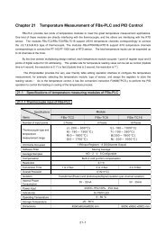
Features<br />
High speed, high performance and low cost<br />
FBs-PLC’s design incorporates a System on Chips (SoC) developed independently by FATEK.<br />
The chip consists of over 120,000 gates which integrate powerful features such as Central<br />
Processing Unit (CPU), hardware logic processor, fi ve high-speed communication ports,<br />
four sets of hardware high-speed counter/timer, four axes of high speed pulse output for NC<br />
positioning with linear interpolation or dynamic tracking, high speed interrupts, and captured<br />
inputs. It presents a higher speed with better functionality and more reliability. Compared to PLC<br />
of its kind, FBs-PLC is the most functional and competitive with a reasonable low price.<br />
Most user friendly, most powerful instruction sets<br />
FBs-PLC has more than 300 instructions, which adopts the most user friendly and readable<br />
multiple-input/multiple-output function structure. As shown in the left fi gure, with one instruction,<br />
three inputs can derive 5 kinds of functions which other brands of PLC may require a lots of<br />
instructions to achieve this. Also the operation result can acquire directly from the outputs. To<br />
increase the program readability, the inputs or outputs for each function instruction have its<br />
own mnemonic symbol attached and the content of each operand also can be shown beneath<br />
it. For high-end application, such as PLC networking(LINK),PID control and NC positioning etc,<br />
FBs-PLC provides the dedicated convenient instructions to help user to reduce barrier in usage.<br />
Communication functions incomparable with up to 5<br />
ports for RS232, RS485, USB, Ethernet<br />
With the help of communication ports inside the SoC, the FBs-PLC are more than suffi cient<br />
even with all fi ve ports operating at the maximum speed (921.6KHz). Communication can be<br />
conducted using ASCII code or the double-speed binary code. Besides the FATEK standard<br />
protocol, Modbus or user-defi nable protocol is also available. FBs-PLC is also provided with<br />
six different communication boards and eight different communication modules for various<br />
applications. It has the most communication ports with highest speed and functionality in the<br />
PLC of its kind. Moreover, each communication port contains LED indicators for transmission<br />
(TX) and reception (Rx) to enable the user to monitor the operation and debug<br />
Highly integrated 8 sets of high-speed counter with<br />
counting frequency up to 920KHz<br />
FBs-PLC, at most, can have 4 sets of hardware high-speed counter (HHSC) and 4 sets of<br />
software high-speed counter (SHSC). The highest counting frequency of HHSC is 120KHz (MC)<br />
or 920KHz (MN). Each HHSC also has clear and mask function. There are 8 counting modes<br />
including U/D, U/Dx2, K/R, K/Rx2, A/B, A/Bx2, A/Bx3 and A/Bx4 which makes the HHSC most<br />
powerful and effi cient. For example, if the encoder, running at 200 pulses per revolution, adopts<br />
A/Bx4 mode can achieve the result that 800 pulses per revolution encoder can provide. Besides,<br />
the counter is implemented by hardware so do not occupy CPU time. Four sets of SHSC has<br />
three counting modes including U/D,K/R and A/B and the total counting frequency is limited to<br />
10KHz.<br />
001 SPD R0<br />
DRV ADR,+,R2,Ps<br />
WAIT TIME 50<br />
GOTO NEXT<br />
002 SPD 20000<br />
DRV ADR,+,9999,Ut<br />
GOTO NEXT<br />
003 SPD 3000<br />
NC control+PLC in one, dedicated NC Position Language,<br />
maximum of 4 axes control for single unit with linear<br />
interpolation<br />
The NC Position Control is incorporated into the SoC of FBs-PLC to integrate PLC+NC control<br />
into one unit in order for resources sharing and reduce the need of dada exchange. The NC<br />
position control adopts dedicated positioning command language, which allows programming by<br />
mechanical or electrical unit and changing control parameters during execution. One single unit<br />
has up to four axes of output with maximum frequency of 120KHz (MC) or 920KHz (MN) and<br />
equips with multi-axial linear interpolation and dynamic tracking. If being combined with the four<br />
sets of built-in HHSC, it can achieve positioning control of closed loop with higher precision.<br />
<br />
<br />
<br />
A maximum of 4 points high-speed pulse width<br />
modulation (HSPWM) output<br />
The SoC inside FBs-PLC incorporates four sets of hardware high-speed pulse width modulation<br />
output, with maximum frequency of 184.32KHz and 18.432KHz with resolutions 1% and 0.1%,<br />
respectively. Different from the PWM function operated by software alone in ordinary PLC, the<br />
hardware driven high-speed PWM in FBs-PLC operates with high precision and stability, which<br />
provides the user easy control with tremendous accuracy.<br />
1
Features<br />
<br />
<br />
<br />
High-speed timer with 0.1mS resolution, the fastest<br />
timer that PLC ever can provide<br />
FBs-PLC is the only PLC providing 0.1mS high-speed timer in the same grade PLC (At most,<br />
FBs-PLC has one set of 16-bit and 4 sets of 32-bit HST.).Currently, the fastest time base of the<br />
timer used in other brands of PLC only reaches 1ms, so can’t work in the application requiring<br />
higher precision. Because the inaccuracy of 0.1ms time base high-speed timer of FBs-PLC<br />
is only 0.1mS, by incorporating interrupt function, FBs-PLC can easily achieve more precise<br />
speed detection or can be used as frequency meter. In most cases, expansive speed detection<br />
equipment can be replaced by this economic wise choice.<br />
Single unit with 16 points of high-speed interrupt<br />
FBs-PLC can provide up to 16 points of external interrupt. The interrupt is driven by edge<br />
and user can defi ne which edge can cause interrupt, positive or negative or both edges. With<br />
interrupt can perform high speed, emergency processing which can’t withstand the time jilter<br />
caused by the delay and deviation of the scan time and can be used for precision high speed<br />
position, machine home, high speed RPM measurement applications.<br />
<br />
<br />
<br />
<br />
<br />
Up to 36 points of captured input in single unit<br />
The SoC in FBs-PLC is capable of capture input, which captures and stores the external pulse<br />
input shorter than scan time for access by CPU. Compared to ordinary PLC that either lacks this<br />
capability or requires highly sophisticated interrupt function which increase the CPU overhead.<br />
FBs-PLC can handle this task easily as general input, which is carefree with high effi ciency and<br />
convenience.<br />
Full line peripherals<br />
Besides 204 models of main unit can be chosen, FBs-PLC also provides 72 models of<br />
expansion I/O and peripherals for selection. The expansion I/O modules include basic DI/O and<br />
AI/O, 7/16-segment LED display module, 8 types(J,K,R,S,E,T,B,N) thermocouple, Pt100, Pt1000<br />
RTD temperature measurement module. FBs-PLC also provide FB-DAP LCD data access panel<br />
which can be linked together with a single RS485 bus. FB-DAP can be simply a Timer/Counter<br />
editor and it can also be used as a simple human machine interface through the function of user<br />
defi nable key and message. Besides, FB-DAP can be equipped with wireless sensing module<br />
and applied to entrance control, parking equipment and elevator control.<br />
Abundant communication driver<br />
The FATEK software drivers of FBs-PLC are supported by world-famous graphic supervisory<br />
software (SCADA) and leading brands of human-machine interfaces, that can be directly<br />
connected with FBs-PLC. Moreover, FATEK also provides Modbus protocol and FATEK DDE<br />
standard communication server software for the user to easily connect FBs-PLC to various<br />
graphic control or computer systems in Offi ce applications or self programming.<br />
User-friendly operating environment<br />
“WinProladder”is a Windows-based ladder diagram programming software for FBs-PLC. It<br />
provides a user-friendly operating environment. Thoughtful and considerate arrangement of<br />
editing, monitor and debugging function let user be familiar with the operation of system in short<br />
time. The powerful editing function of WinProladder, assisted with keyboard, mouse, online<br />
help of ladder instruction and operating guide, can greatly improve your working effi ciency. The<br />
features which can show the register’s data directly in the ladder diagram and provides multiple<br />
status page monitoring let user be able to conduct status monitoring and debugging easily.<br />
2
Symtem Configuration<br />
Computer MIS HMI Server<br />
PLC<br />
Ethernet<br />
Intelligent Devices<br />
Communication Modules<br />
FBs-PACK<br />
(Port 4)<br />
Ethernet<br />
FBs-CM25E<br />
Up to 920KHz max.<br />
Computer<br />
DI HSC 0 HSC 1 HSC 2 HSC 3<br />
Port 4<br />
FBs-CM55E<br />
HMI<br />
RS232/RS485<br />
SCADA<br />
Port 3<br />
RS232/RS485<br />
FBs-CM22<br />
FBs-CM25<br />
AC<br />
Power<br />
Main Units<br />
Economical<br />
Bar-code Reader<br />
FBs-CM55<br />
FBs-10/14MA<br />
(-D)<br />
FBs-20/24MA<br />
(-D)<br />
FBs-32/40MA<br />
(-D)<br />
FBs-60MA<br />
(-D)<br />
Scale<br />
Port 0<br />
Port 4<br />
Port 3<br />
Port 0<br />
Highperfermance<br />
RS232/USB<br />
Port 2<br />
Port 1<br />
FBs-10/14MC<br />
(-D)<br />
FBs-20/24MC<br />
(-D)<br />
FBs-32/40MC<br />
(-D)<br />
FBs-60MC<br />
(-D)<br />
PLC<br />
Communication Boards<br />
NC<br />
Position<br />
FBs-CB2<br />
FBs-20MN<br />
(-D)<br />
FBs-32MN<br />
(-D)<br />
FBs-44MN<br />
(-D)<br />
Port 2<br />
RS232/RS485<br />
FBs-CB22<br />
DC<br />
Power<br />
FB-07C<br />
FBs-CB25<br />
Port 1<br />
RS232/RS485<br />
FBs-CB5<br />
DO HPSO0 HPSO1 HPSO2 HPSO3<br />
FBs-CB55<br />
Up to 920KHz max.<br />
FB-DAP-B/C(R)<br />
Computer MIS HMI Server<br />
PLC<br />
RFID Card<br />
Port 1<br />
FBs-CBE<br />
Ethernet<br />
Ethernet<br />
3
Symtem Configuration<br />
Digital I/O Expansion Units<br />
DI<br />
AC<br />
Power<br />
24 VDC<br />
FBs-60EAP FBs-40EAP FBs-24EAP<br />
DO<br />
DC<br />
Power<br />
FBs-60EAP-D FBs-40EAP-D FBs-24EAP-D<br />
Digital I/O Expansion Modules<br />
DI<br />
FBs-60EA FBs-40EA FBs-24EA FBs-16EA<br />
DO<br />
FBs-16EY FBs-20EX FBs-8EX FBs-8EY FBs-8EA FBs-24EX FBs-24EYT<br />
Analog I/O Expansion Modules<br />
AI<br />
AO<br />
AC<br />
Power<br />
Power Supply for Expansion Modules<br />
FBs-6AD FBs-2DA FBs-4DA FBs-4A2D<br />
24 VDC<br />
LED<br />
DC<br />
Power<br />
FBs-EPOW<br />
FBs-EPOW-D<br />
Thumbwheel Switch Input and<br />
7/16-segment LED Display Modules<br />
Thumbwheel<br />
Switch<br />
FBs-7SG1 FBs-7SG2 FBs-32DGI<br />
Thermocouple<br />
Temperature Measurement Expansion Modules<br />
RTD<br />
FBs-TC2<br />
FBs-TC6<br />
FBs-RTD6<br />
FBs-TC16<br />
FBs-RTD16<br />
4
Main Functions and Applications<br />
Communication<br />
• Communication<br />
Connection with intelligent peripherals:<br />
The five communication ports in FBs-PLC can<br />
simultaneously connect to various intelligent<br />
peripherals with available interfaces such as USB,<br />
RS232, RS485, and Ethernet. Besides adopting<br />
FATEK standard communication protocol or Modbus<br />
protocol, or conducting communication through the<br />
FATEK communication server, the user also can use<br />
CLINK commands to define the dedicated protocol<br />
to actively or passively establish the connection with<br />
any intelligent peripherals.<br />
Sample application<br />
• • <br />
FBs-CM25E<br />
(Port4)*<br />
FBs-PLC<br />
Port4<br />
Port0<br />
Port3<br />
Port2<br />
Port1<br />
*Use the RS485 port4<br />
to bridge the Ethernet<br />
Ethernet (mulit-drop), Master or slave<br />
RS-232(single)/RS485(multi-drop), Master or Slave<br />
RS-232(single)/RS485(multi-drop), Master or Slave<br />
RS-232(single)/RS485(multi-drop), Master or Slave<br />
RS-232(single)/RS485(multi-drop), Master or Slave<br />
RS-232(single)/USB(single), Slave only<br />
High-speed CPU link:<br />
The Port 2 with optional RS485 interface can be<br />
used as the high-speed LINK between up to 254<br />
FATEK PLC units, accomplished with merely<br />
one CLINK command at the main station. The<br />
communication speed can be up to 921.6Kbps,<br />
which is suitable to application of distributed real<br />
time control on multiple PLC units. (Only exchange<br />
the data in the high-speed common data areas,<br />
which may occupy more CPU time of PLC because<br />
of the frequently real time update.)<br />
Sample application<br />
• • <br />
FBs-PLC FBs-PLC FBs-PLC FBs-PLC FBs-PLC<br />
(up to 921.6 Kbps)<br />
RS485 b us<br />
Max. 254 stations(Processed during communication interrupt)<br />
5
Main Functions and Applications<br />
Communication<br />
General CPU link:<br />
The RS485 interface in any of port1~port4 can link<br />
between up to 254 FATEK PLC units, accomplished<br />
with merely one CLINK command at the main<br />
station. It is suitable for distributed data collection<br />
and application of non-real time control. (Any data<br />
in PLC can conduct Link exchange, since non-real<br />
time update, which occupies less CPU time of PLC.)<br />
Sample application<br />
• • <br />
FBs-PLC FBs-PLC FBs-PLC FBs-PLC FBs-PLC<br />
(up to 921.6 Kbps)<br />
RS485 bus<br />
Max. 254 stations(Processed by normal scan loop)<br />
Modem for remote communication:<br />
Through MODEM, various functions such as<br />
remote program modification, control, diagnosis<br />
and monitoring can be performed even at the office<br />
distant from overseas.<br />
Sample application<br />
• • <br />
FBs-PLC<br />
MODEM<br />
MODEM<br />
CPU link through MODEM:<br />
Through ladder diagram program, FBs-PLC can<br />
control MODEM to dial automatically to link with<br />
remote MODEM and PLC without the intervention<br />
of operator or computer. With this function, the<br />
headquarter of company can connect to branch<br />
factories automatically to perform the data<br />
collecting, data monitoring, alarm logging and<br />
abnormal report and etc.<br />
Sample application<br />
FBs-PLC<br />
MODEM<br />
• • <br />
MODEM<br />
FBs-PLC<br />
Calling through pager or mobile phone:<br />
In an emergency situation, before disaster happens<br />
or operator awares the situation, PLC program can<br />
detect this and call out to maintenance personnel<br />
or security personnel. So the situation can be<br />
taken care of at the first moment. The feature is<br />
especially suitable for the applications of fire alert,<br />
guard security and other application requiring high<br />
security.<br />
Sample application<br />
FBs-PLC<br />
• • <br />
MODEM<br />
Pager<br />
SMS<br />
GSM/GPRS<br />
MODEM<br />
Internet<br />
LAN<br />
Computer<br />
The RS485 repeater or Hub can be applied<br />
in long distance or special topological<br />
routing:<br />
Use the Repeater or Hub of the RS485 interface<br />
to extent the coverage distance and to meet the<br />
variety of wiring topology demand (such as Bus or<br />
Star structure).<br />
Sample application<br />
• • <br />
FBs-PLC<br />
FBs-PLC<br />
FBs-PLC<br />
FBs-PLC<br />
FBs-CM5R<br />
(Repeater)<br />
FBs-PLC<br />
FBs-CM5H<br />
(Hub)<br />
FBs-PLC<br />
The RS485 repeater FBs-CM5R can<br />
be used to extend the distance and<br />
expand the range of RS485 network<br />
Star connection of RS485 can be realized<br />
by using FBs-CM5H(Hub) to meet the<br />
requirement of special topological routing.<br />
6
Main Functions and Applications<br />
High-speed counter (HSC)<br />
• High-speed counter<br />
(HSC)<br />
A FBs-PLC can have up to 8 sets of 32bits<br />
high-speed counter. Among which, 4 sets are<br />
hardware high-speed counter (HHSC) whose<br />
counting frequency can reach 120KHz (MC)or<br />
920KHz (MN) and can operate with 8 counting<br />
modes. The other 4 sets are software high-speed<br />
counter (SHSC) whose total input frequency can<br />
reach 10KHz and can operate with three counting<br />
modes. The high-speed counters can be used in the<br />
applications required high-speed processing and<br />
precision control.<br />
Up/Down<br />
pulse<br />
Pulse-<br />
Direction<br />
A/B phase<br />
Counting<br />
(MODE)<br />
HHSC<br />
(HSC0 ~ 3)<br />
SHSC<br />
(HSC4 ~ 7)<br />
MD 0 U/D O O<br />
MD 1 U/Dx2 O<br />
MD 2 K/R O O<br />
MD 3 K/Rx2 O<br />
MD 4 A/B O O<br />
MD 5 A/Bx2 O<br />
MD 6 A/Bx3 O<br />
MD 7 A/Bx4 O<br />
U<br />
D<br />
U<br />
D<br />
K<br />
R<br />
K<br />
R<br />
A<br />
B<br />
A<br />
B<br />
A<br />
B<br />
A<br />
B<br />
Operation Waveform<br />
Up count (+1) Down count (-1)<br />
Sample application<br />
• • <br />
The control of cutting machine with variable length<br />
A<br />
B<br />
Motor<br />
Encoder<br />
Cutting length<br />
setting<br />
Inverter<br />
FB-DAP<br />
FBs-PLC<br />
FBs-2DA<br />
Speed command<br />
Roller<br />
Cutter<br />
7
Main Functions and Applications<br />
High-speed timer (HST) / NC position control<br />
• High-speed timer<br />
(HST)<br />
FBs-PLC has a special design 0.1mS time base<br />
high-speed timer that can provide a timer with<br />
0.1mS resolution and real-time time-up interrupt<br />
capability. Compared with ordinary PLC, whose<br />
best resolution is 1mS, including error of scan<br />
time, FBs-PLC is more than 10 times as precise<br />
as ordinary PLC. So FBs-PLC can easily handles<br />
precise timing or speed detection that can not be<br />
handled with other PLCs. FBs-PLC has one 16-bit<br />
0.1mS high-speed timer. Besides that, four sets<br />
of 32-bit hardware high-speed counter(HHSC) all<br />
have software switch, can be configured as 32-bit<br />
0.1mS high-speed timer. Therefore, FBs-PLC has<br />
maximum of 4 sets of 32-bit HST.<br />
Sample application<br />
Combine HSC and HST to detect the break or blunting of drill.<br />
Emcoder<br />
Motor<br />
Elevating<br />
mechanism<br />
• • <br />
HSC<br />
input<br />
Drill<br />
position<br />
Drilling distance<br />
If a drill is running without loading, its rotating<br />
speed is 6000RPM. When drill is in normal drilling,<br />
rotating speed will be reduced to 5500RPM. When<br />
drill becomes blunt then friction force is increased,<br />
rotating speed will be further reduced to 5200RPM.<br />
When drill is broken, rotating speed is equal to<br />
the speed running without loading. When drill is<br />
pressed down, the change of rotating speed can be<br />
detected. So, the break and blunting of drill can be<br />
disposed immediately.<br />
FBs-PLC<br />
HSC<br />
Speed detecting period<br />
• NC position control<br />
High-speed pulse output (HSPSO) built in<br />
FBs-PLC can perform up to 4 axes NC servo or<br />
stepping position control. With the accelerating<br />
and decelerating function, it is easy to achieve<br />
smooth and precise multi-zone position control. If<br />
coordinating with built-in HHSC feedback, FBs-PLC<br />
can perform closed loop control to compensate the<br />
wear, aging and unconformity of component thus<br />
can obtain more precise control. Besides, FBs-PLC<br />
provides a position control language, which<br />
cooperates with the convenient instruction of ladder<br />
diagram, can facilitate the implementation of your<br />
precise position control.<br />
Sample application<br />
• • <br />
Use one PLC to perform 3 axes position control.<br />
PSO1<br />
FBs-44MN<br />
Pulse command<br />
output<br />
Z axis motor<br />
Servo driver<br />
PSO2<br />
X axis motor<br />
PSO3<br />
Y axis motor<br />
PSO2, PSO3 are used for X,Y table two dimensions position control. PSO1 is used for<br />
position control of drilling depth.<br />
8
Main Functions and Applications<br />
High-speed pulse width modulation (HSPWM) / High-speed interrupt<br />
• High-speed pulse<br />
width modulation<br />
(HSPWM)<br />
Sample application<br />
• • <br />
FBs-PLC provides 4 points of hardware high-speed<br />
pulse width modulation output, with resolution as<br />
good as 0.1% (for frequency 72Hz~18.432KHz) and<br />
1% (for frequency 720Hz~184.32KHz), respectively.<br />
Because of the high speed of hardware circuits and<br />
precision and stability, FBs-PLC can easily achieve<br />
fi ne temperature control, proportional valve control,<br />
or simple and yet practical D/A output made with<br />
external integration circuits.<br />
FBs-PLC<br />
<br />
<br />
<br />
<br />
<br />
<br />
<br />
<br />
<br />
<br />
<br />
<br />
<br />
<br />
<br />
<br />
<br />
<br />
<br />
<br />
<br />
<br />
<br />
<br />
• High-speed interrupt<br />
A FBs-PLC can have up to 16 points of external<br />
interrupt input. The interrupt can be activated by<br />
the change of input status which can be positive<br />
edge/negative edge or both edges. When using the<br />
input interrupt function can avoid the false operation<br />
that caused by the PLC can’t detect the status<br />
change of the fast input signal with normal scan.<br />
Sample application<br />
• • <br />
Motor<br />
Encoder<br />
Traction<br />
machine<br />
Sample Application: Elevator position control<br />
Incremental encoder can detect the position and the<br />
fl oor where the box of cage locating to do multiple<br />
sections of deceleration. Then, use photo sensor<br />
and stop plate to detect cage stop signal and issue<br />
a high-speed interrupt to immediate stop the cage<br />
precisely.<br />
FBs-PLC<br />
Stopper<br />
Photo<br />
Sensor<br />
Speed<br />
First<br />
deceleration<br />
zone<br />
Second<br />
deceleration<br />
zone<br />
Cage<br />
Stop<br />
immidiately<br />
Position<br />
9
Main Functions and Applications<br />
General purpose PID control / Temperature measurement and PID control<br />
• General purpose PID<br />
control<br />
FBs-PLC provides the general purpose PID control<br />
function which compares the process variables,<br />
read from analog input (AI), with the setting value,<br />
defined by user, and perform PID calculation<br />
according to the proportional band (P), integral<br />
constant (I) and derivative constant (D). A proper<br />
output control value obtained from above execution<br />
is output through analog output (AO) to control<br />
process to stay within the range specified by user.<br />
The feature can be applied to smooth, precise<br />
control such as flow, pressure and level control<br />
Sample application<br />
Level<br />
setting<br />
FBs-PLC<br />
• • <br />
Amplifier<br />
FBs-2DA<br />
Control<br />
valve<br />
FB-DAP<br />
level<br />
sensor<br />
Liquid<br />
Released<br />
valve<br />
FBs-6AD<br />
• Temperature<br />
measurement and PID<br />
control<br />
FBs-PLC provides a 8 types (J,K,R,S,E,T,B,N)<br />
of thermocouple temperature module as well as<br />
Pt-100 and Pt-1000 RTD temperature module.<br />
Thermocouple is suitable for the measurement<br />
of large temperature range such as boiler<br />
process. RTD is good for the measurement of<br />
low temperature, smaller range of temperature<br />
and higher resolution such as refrigeration and air<br />
condition application. Because of the characteristic<br />
of temperature changing slowly, adopting<br />
multiplexing scan measurement and multiple<br />
loops PID control make single FBs-PLC be able to<br />
perform up to 32 loops PID temperature control. So,<br />
can get the best cost to performance ratio. With the<br />
convenient instruction of temperature measurement<br />
and temperature PID control will drastically reduce<br />
the difficulties, cost and time for developing and<br />
testing program.<br />
Sample application:<br />
Injection molding machine temperature control<br />
As shown in the right figure, FBs-TC6 can connect<br />
with 8 types (J,K,R,S,E,T,B,N) of thermocouple<br />
directly. Through the execution of temperature<br />
measurement and PID control instruction, output<br />
the control output through SSR to control heater<br />
to maintain the temperature of each zone within<br />
specified range.<br />
Sample application<br />
FBs-24MCT<br />
FBs-TC6<br />
• • <br />
Hopper<br />
Heater<br />
J,k...type<br />
thermocouple<br />
SSR SSR SSR SSR SSR<br />
10
Main Functions and Applications<br />
Thumbwheel switch multiplex input / 7/16-segment LED display module<br />
• Thumbwheel switch multiplex input<br />
The FBs-32DGI thumbwheel switch multiplex input module provided in FBs-PLC conduct multiplexing input scan of the eight sets of 4 digit numbers (or 128<br />
independent ON/OFF status) via the embedded I/O ASIC chips (special chips for the FBs-PLC I/O module). It does not occupy any CPU time and the multiplexing<br />
scan rate is about 10ms. In addition, because only 24 wires are required by multiplexing input to achieve 32 digits (or 128bit ON/OFF) input, plus that the FBs-32DGI<br />
is only 4cm in width, it turn out to be an ultra high density, lowest cost, and most labor saving solution.<br />
Sample application<br />
• • <br />
Thumbwheel switch module<br />
<br />
<br />
<br />
<br />
<br />
<br />
<br />
<br />
<br />
<br />
<br />
<br />
<br />
<br />
<br />
<br />
<br />
<br />
<br />
<br />
<br />
<br />
<br />
<br />
<br />
<br />
<br />
<br />
<br />
<br />
<br />
<br />
<br />
<br />
<br />
<br />
<br />
<br />
<br />
<br />
<br />
Connection for<br />
independent switch input<br />
• 7/16-segment LED display module<br />
The FBs-7SG is a 7/16-segment LED display module with only 4cm width. The embedded I/O ASIC chips will automatically conduct the multiplexing scan display of<br />
two sets of 8 digits (a total of 16 digits) 7-segment LED display or 8 sets of 16-segment LED display without occuping CPU time. The multiplexing scan time is 10ms.<br />
Furthermore, because of multiplexing scan, each set of 8 digits (64bit LED) only requires the 16pins ribbon cables for connection. Three different driving voltages and<br />
three voltage fine tuning are available in this module, which are capable of driving most of existing 7-segment LED displays of which the driving voltage is various.<br />
The installation distance of display can even reach up to one hundred meters. FATEK also provides 4(.56”, .8”, 2.3”, and 4.0”) 7 segment LED display boards and 2(.8<br />
”, 2.3”) 16-segment alphanumeric LED display for the choice of users.<br />
Sample application<br />
• • <br />
FBs-PLC FBs-7SG2 or<br />
<br />
<br />
<br />
<br />
<br />
<br />
<br />
<br />
<br />
7-segment display<br />
independent LED<br />
Nondecoded<br />
LED<br />
number<br />
<br />
<br />
<br />
<br />
<br />
<br />
<br />
<br />
<br />
<br />
<br />
<br />
<br />
<br />
<br />
<br />
<br />
Decoded display <br />
digit number<br />
<br />
<br />
<br />
<br />
<br />
<br />
<br />
<br />
<br />
11
Main Functions and Applications<br />
Simple human-machine interface and RFID card<br />
• Simple human-machine interface and RFID card<br />
FB-DAP can be used for setting Timer/Counter and displaying NC position. It also can be used for simple human-machine interface by using the features of user<br />
definable key and display message. The FB-DAP with -R option is equipped with wireless card reader module and can be used for the application of entrance ,<br />
elevator, security control and calling car in parking tower. Besides, FB-DAP uses extra-large membrane keypad, which is easy to be distinguished and operated.<br />
Example 1<br />
To set Timer/Counter and to display NC position<br />
• • <br />
Use reference number (T, C, R) or document name (1~16 English characters or numbers)to specify monitoring object<br />
Monitoring by<br />
reference number<br />
Monitoring by<br />
document name<br />
FB-DAP<br />
FBs-PLC<br />
Equipment<br />
under<br />
control<br />
Example 2<br />
• • <br />
Used as alarm or message display<br />
This mode can be as dedicated mode or a background mode. In dedicated mode, FB-DAP is only for displaying. In background mode,<br />
FB-DAP works in pre-defined working mode (such as T/C setting and entrance control etc.) while in normal situation. FB-DAP will display<br />
alarm message (predefined in program) or display event message(the message can be changed by user without modifying the program)<br />
only when alarm or special event happens. The buzzer alarm is optional.<br />
Normal display screen<br />
(Timer/Counter setting)<br />
Auto change<br />
Alarm 1<br />
Alarm 2<br />
Alarm 3<br />
The screen when alarm<br />
occurred<br />
FB-DAP<br />
FBs-PLC<br />
Can set 10 grades of alarm and event display message. When the length of event display<br />
message exceeds 16 characters, FB-DAP will display the message with slow scroll.<br />
Example 3<br />
• • <br />
The application of entrance and parking control with multi-DAP link and RFID card<br />
RFID<br />
card<br />
RFID<br />
card<br />
RFID<br />
card<br />
RFID<br />
card<br />
Windows based<br />
Program Development Tool<br />
WinProladder software package<br />
FATEK FBs-PLC Ladder Program Programming Software<br />
• General Feature<br />
Windows based application program, all the operating follow the convention of windows environment, easy for learning and operating. No matter beginner or Pro<br />
can operate with great effi cient.<br />
Adopt project concept, which category the whole tasks of program to be developed with hierarchy tree. Through the visual effect the user can see through the<br />
whole project at fi rst glance. No matter at program or maintenance stage all the jobs need to do can perform with intuitive.<br />
Thoughtful and considerate entry method design, incorporate both the keyboard and mouse for entry device. No matter at fi eld site or offi ce environment can<br />
operate with ease and effi cient.<br />
Provides the connection for PLC and PC with varieties. Among the connections, there are hardware connection, Modem connection and Internet connection.<br />
For every different connection, WinProladder provide a session name to associate the setting of the communication parameters, such as port no., baud rate, IP<br />
address, phone number, etc.. With this feature can alleviate the user from the burden of the memorizing.<br />
WinProladder<br />
• Program editing<br />
Provides the on-line program editing capability. After modify the ladder<br />
program can send the RUN command immediately without to re-download the<br />
program to PLC. With this feature can reduce the application development<br />
time dramatically comparing with other PLC without this feature.<br />
Ladder program can be edited without stop the PLC from running (Run time<br />
editing).<br />
Multiple ladder program windows, can show different fragmentation of ladder<br />
program at one time and perform the copy, paste and compare operation<br />
between these windows.<br />
Provides the fl exible ladder network editing capability. With the help of copy,<br />
paste and delete highly effi cient operation can complete a complex program<br />
with few keystrokes.<br />
Provides the capability to divide the whole program into many program units.<br />
User can at will partition the whole development task into many independent<br />
program units according to the functionality or other classify methodology and<br />
perform the entry, editing, testing and documentation independently. With this<br />
feature can greatly ease the maintenance of the whole application.<br />
Provides an individual window for mnemonic instruction display. Immediately<br />
display the equivalent mnemonic code corresponding to the ladder network<br />
pointed by the cursor.<br />
Provides the fl exible program search capability, can search contact, register<br />
or function. Also can set a fi lter to narrow down the search object to ease the<br />
user from picking up the desire results among the whole bunches of search<br />
result. Most of all, just double click the interested message line can bring out<br />
the corresponding ladder program to the user.<br />
Provides a powerful syntax check tool. With this tool can parse the user's<br />
program and generate a parsing message in one window. In this window all the<br />
warning or error messages regard the program will be listed line by line. User<br />
just double click the interested line then the ladder program will be shown on<br />
the window with the cursor stay on the question part.<br />
13
WinProladder software package<br />
Windows based<br />
Program Development Tool<br />
• Program testing<br />
Provides multiple pages of status monitoring. User can monitor and modify the status of discrete contacts and registers on the status page. Each discrete input<br />
and output (include the internal relay) can be disabled and forced on or off. Each register can be selected individually to show with different format such as<br />
hexadecimal, decimal and binary. Best of all, all the layout of the status pages can be stored in the project and there is no need for user to re-defi ne the page each<br />
time when he/she wants to monitor the status.<br />
Multiple high lighted ladder program display windows. The conducting condition of each contact element can be revealed by the color of the element drawing. The<br />
register value embedded with the function block also can be shown currently with ladder diagram. The discrete element can be easily disabled and forced on or off<br />
directly from the ladder diagram.<br />
• Program documentation<br />
Provides discrete element, register, network, and program unit and project comment. Besides the project comment all other comments can be displayed with<br />
ladder diagram. With this feature the user can easily realize how the ladder program is working.<br />
Provides following report printout function:<br />
Ladder diagram printout can select the scope and detail level of the ladder diagram for different kind of reporting requirements.<br />
Used ladder element cross-reference report can list the statistics of all ladder elements used in the project.<br />
The comment of the contact and register can be created by this software or by using text editor that were familiar with user. Comments can be imported from the<br />
text fi le and also can be exported to the application software such as Excel for further processing.<br />
The network of ladder program can be copied to other editing software such as Word by using copy and paste function. With this feature, can facilitate the<br />
documentation of program when use the editing software.<br />
• Project oriented program<br />
Adopt project concept, which category the whole tasks of<br />
program to be developed with hierarchy tree. Through the<br />
visual effect the user can see through the whole project at<br />
fi rst glance. No matter at program or maintenance stage all<br />
the jobs needto do can be performed with intuitive.<br />
14
Windows based<br />
Program Development Tool<br />
WinProladder software package<br />
• Ladder program<br />
editing screen<br />
Multiple ladder windows, can perform the network<br />
copy, paste, cut and compare operations among<br />
windows.<br />
• Status monitor and<br />
control<br />
Multiple status page window, can defi ne the<br />
elements, registers to be monitoring and assign its<br />
display format. The state of the contact elements<br />
can be disabled and forced. Register value also can<br />
be entered.<br />
Display with different data formats<br />
Multi-page status monitoring<br />
Monitoring status with comment display<br />
Multiple high lighted ladder program windows. The<br />
conducting condition of each contact element can<br />
be revealed by the color of the element drawing.<br />
The register value embedded with the function block<br />
also can be shown currently with ladder diagram.<br />
Control the contact<br />
status directly on ladder<br />
program screen<br />
Conducting<br />
status of contact<br />
with disable<br />
indication<br />
The live content<br />
of register can be<br />
shown directly on<br />
ladder diagram<br />
Coil conducting<br />
status with<br />
disable<br />
indication<br />
15
WinProladder software package<br />
Windows based<br />
Program Development Tool<br />
• Mnemonic ladder<br />
instruction display<br />
window<br />
Dedicate mnemonic instruction window can show<br />
the mnemonic instructions corresponding to the<br />
network pointed by the cursor. This feature can help<br />
the teaching of ladder programming by mnemonic<br />
instruction.<br />
• Ladder diagram with<br />
comments<br />
Network<br />
comment<br />
Register<br />
comment<br />
Provides different detail level of comment for<br />
contact, register, network, program unit and program<br />
to facilitate the readability and maintenance of the<br />
program.<br />
Digital<br />
element<br />
comment<br />
• Element comment<br />
editing<br />
With element comment window, can attach an<br />
easy for memorizing comment to the elements,<br />
detail description also can be added to facilitate the<br />
maintenance of project<br />
Can choose<br />
all, used,<br />
unused<br />
elements for<br />
displaying to<br />
assist the user<br />
to input the<br />
comments<br />
The comment,<br />
through<br />
exporting and<br />
importing can<br />
be integrated<br />
with other<br />
application<br />
software.<br />
16
Instruction Sets<br />
Sequential instructions / Step ladder instructions (SFC) / Function instructions<br />
• Sequential instructions<br />
Instructions Operand Ladder symbol Function Instructions Operand Ladder symbol Function<br />
ORG<br />
Network starts by an A contact<br />
OR<br />
Parallel connect with an A contact<br />
ORG NOT<br />
ORG TU<br />
X,Y,M,<br />
S,T,C<br />
Network starts by a B contact<br />
Network starts by a TU contact<br />
OR NOT<br />
OR TU<br />
X,Y,M,<br />
S,T,C<br />
Parallel connect with a B contact<br />
Parallel connect with a TU contact<br />
ORG TD Network starts by a TD contact OR TD Parallel connect with a TD contact<br />
ORG OPEN Network starts by an open contact OR OPEN Parallel connect with an open contact<br />
ORG SHORT Network starts by a short contact OR SHORT Parallel connect with a short contact<br />
LD<br />
Branch line starts by an A contact ANDLD Concatenate two blocks in series<br />
LD NOT<br />
LD TU<br />
X,Y,M,<br />
S,T,C<br />
Branch line starts by a B contact<br />
Branch line starts by a TU contact<br />
ORLD<br />
OUT<br />
Merge two blocks in parallel<br />
Output result to coil<br />
Y,M,S<br />
LD TD Branch line starts by a TD contact OUT NOT Output the inverse of result to a coil<br />
LD OPEN Branch line starts by an open contact OUT L Y Output result to a retentive coil<br />
LD SHORT Branch line starts by a short contact OUT<br />
Store node status in temporary relay<br />
TR<br />
AND<br />
Serial connect with an A contact LD Retrieve node status from temporary relay<br />
AND NOT Serial connect with a B contact TU Take differential up of node status to node status<br />
X,Y,M,<br />
S,T,C<br />
Take differential down of node status to node<br />
AND TU Serial connect with a TU contact TD<br />
status<br />
AND TD Serial connect with a TD contact NOT Inverse node status<br />
AND OPEN Serial connect with an open contact SET Set a coil<br />
AND SHORT Serial connect with a short contact RST Reset a coil<br />
• Step ladder instructions (SFC)<br />
Instructions Operand Ladder symbol Function Instructions Operand Ladder symbol Function<br />
STP Snnn Define STEP program TO<br />
STEP divergence<br />
Snnn<br />
STPEND STEP program end FROM STEP convergence<br />
• Function instructions<br />
Category NO. Instruction Derivative Function<br />
Timer Tnnn General timer instruction (T0 ~ T255)<br />
Counter Cnnn General counter instruction (C0 ~ C255)<br />
Setting /<br />
Resetting<br />
Digital<br />
operation<br />
Mathematical<br />
operation<br />
SET DP Set all bits of register or a discrete point to 1<br />
RST DP Clear all bits of register or a discrete point to 0<br />
114 Z-WR P Zone set or clear<br />
4 DIFU<br />
5 DIFD<br />
Take differential up of the node status to<br />
operand<br />
Take differential down of the node status to<br />
operand<br />
10 TOGG Toggle the coil status<br />
11 (+) DP Sa+Sb → D<br />
12 (−) DP Sa−Sb → D<br />
13 ( × ) DP Sa × Sb → D<br />
14 ( ÷ ) DP Sa ÷ Sb → D<br />
15 (+1) DP Add 1 to D<br />
16 (−1) DP Subtract 1 from D<br />
23 DIV48 P 48 bits integer division Sa ÷ Sb → D<br />
24 SUM DP Sum of N consecutive values<br />
25 MEAN DP Average of N consecutive values<br />
26 SQRT DP Square root of S<br />
27 NEG DP Two’s complement of D (Negative number)<br />
28 ABS DP Absolute value of D<br />
29 EXT P Extend 16 bits into 32 bits<br />
30 PID P PID calculation<br />
Category NO. Instruction Derivative Function<br />
Mathematical<br />
operation<br />
Logic<br />
operation<br />
Comparision<br />
31 CRC16 P CRC16 calculation<br />
32 ADCNV<br />
Offset and full scale conversion for analog<br />
I/O<br />
200 I→F DP Integer to floating point number conversion<br />
201 F→I DP Floating point number to integer conversion<br />
202 FADD P Addition of floating point number<br />
203 FSUB P Subtraction of floating point number<br />
204 FMUL P Multiplication of floating point number<br />
205 FDIV P Division of floating point number<br />
206 FCMP P Comparison of floating point number<br />
207 FZCP P Zone comparison of floating point number<br />
208 FSQR P Square root of floating point number<br />
209 FSIN P SIN trigonometric function<br />
210 FCOS P COS trigonometric function<br />
211 FTAN P TAN trigonometric function<br />
212 FNEG P Change sign of floating point number<br />
213 FABS P Absolute value of floating point number<br />
18 AND DP Sa AND Sb<br />
19 OR DP Sa OR Sb<br />
35 XOR DP Sa XOR Sb<br />
36 XNR DP Sa XNR Sb<br />
17 CMP DP Value Compare<br />
37 ZNCMP DP Zone Compare<br />
17
Instruction Sets<br />
Function instructions<br />
(Continues)<br />
Category NO. Instruction Derivative Function<br />
Move<br />
operation<br />
8 MOV DP Move S to D<br />
9 MOV/ DP Inverse S and move to D<br />
40 BITRD DP Move the Bit-N of S to FO<br />
41 BITWR DP Write INB input to the Bit-N of D<br />
42 BITMV DP Move the Bit-Ns of S to the Bit -Nd of D<br />
43 NBMV DP Move the Nibble-Ns of S to the Nibble-Nd of D<br />
44 BYMV DP Move the Byte-Ns of S to the Byte-Nd of D<br />
45 XCHG DP Exchange Da and Db<br />
46 SWAP P Swap the High-Byte of D with the Low-Byte of D<br />
47 UNIT P Take Nb0 of N words to form a Word<br />
48 DIST P Distribute N Nb of S to Nb0 of N Words<br />
49 BUNIT P Low byte of words re-unit<br />
50 BDIST P Words split into multi-byte<br />
160 RW-FR DP File register access<br />
Category NO. Instruction Derivative Function<br />
I/O<br />
instruction<br />
Cumulative<br />
Timer<br />
Monitor and<br />
control<br />
HSC/<br />
HST<br />
80 MUXI Multiplexing input convenient instruction<br />
81 PLSO D Pulse output(PSO) instruction<br />
82 PWM<br />
Pulse width modulation output (PWM)<br />
instruction<br />
83 SPD Speed detection instruction<br />
84 TDSP 7/16-segment LED display control<br />
86 TPCTL PID temperature control<br />
139 HSPWM Hardware PWM pulse output<br />
87 T.01S 0.01S time base cumulative timer<br />
88 T.1S 0.1S time base cumulative timer<br />
89 T1S 1S time base cumulative timer<br />
90 WDT P Set the watchdog timer<br />
91 RSWDT P Reset watchdog timer<br />
92 HSCTR<br />
93 HSCTW<br />
Read CV of hardware high speed<br />
counter/timer<br />
Write CV or PV of hardware high speed<br />
counter/timer<br />
Shift /<br />
Rotation<br />
6 BSHF DP Shift D right 1 bit or left 1 bit<br />
51 SHFL DP Shift D left N bits<br />
52 SHFR DP Shift D right N bits<br />
53 ROTL DP Rotate D left N bits<br />
54 ROTR DP Rotate D right N bits<br />
20 →BCD DP Convert S into BCD<br />
Text 94 ASCWR Output ASCII message<br />
Ascend/<br />
Descend<br />
Communication<br />
95 RAMP<br />
Ascending/Descending convenient<br />
instruction<br />
150 M-BUS Modbus protocol communication<br />
151 CLINK Fatek/Generic protocol communication<br />
100 R→T DP Move register Rs to the table Td<br />
101 T→R DP Move table Ts to register Rd<br />
21 →BIN DP Convert S into Binary<br />
55 B→G DP Binary to Gray code conversion<br />
56 G→B DP Gray code to Binary conversion<br />
57 DECOD P Decode the NS ~ NL of S<br />
102 T→T DP<br />
Move the Rp of table Ts to the Rp of table<br />
Td<br />
103 BT_M DP Move table Ts to table Td<br />
104 T_SWP DP Swap Ta and Tb<br />
105 R-T_S DP Search Rs from table Ts<br />
Code<br />
conversion<br />
58 ENCOD P Encode the NS ~ NL of S<br />
59 →7SG P Convert N+1’ Nb of S into 7-segment code<br />
Table<br />
operation<br />
106 T-T_C DP Compare table Ta and table Tb<br />
107 T_FIL DP Fill Rs into Td table<br />
60 →ASC P Convert character/number into ASCII code<br />
61 →SEC P Represent hour, minute, second by seconds<br />
62 →HMS P Represent second by hour, minute and second<br />
63 →HEX P Convert ASCII code into hexadecimal<br />
64 →ASCII P Convert hexadecimal into ASCII code<br />
108 T_SHF DP Shift table left or right<br />
109 T_ROT DP Rotate table left or right<br />
110 QUEUE DP First in first out (Queue) instruction<br />
111 STACK DP First in last out (Stack) instruction<br />
112 BKCMP DP<br />
Compare Rs with zone defined by two<br />
tables<br />
0 MC Master control loop start<br />
1 MCE Master control loop end<br />
2 SKP The start of the skip loop<br />
3 SKPE The end of the skip loop<br />
113 SORT DP Sort the table<br />
120 MAND P AND two matrixes<br />
121 MOR P OR two matrixes<br />
122 MXOR P XOR two matrixes<br />
123 MXNR P XNR two matrixes<br />
Flow<br />
control<br />
END<br />
Terminate the execution of program<br />
(for debugging)<br />
22 BREAK P Exit from FOR-NEXT loop<br />
65 LBL Define the string as label<br />
66 JMP P Jump instruction<br />
67 CALL P Call instruction<br />
68 RTS Subroutine return instruction<br />
69 RTI Interrupt return instruction<br />
Matrix<br />
operation<br />
124 MINV P Inverse matrix<br />
125 MCMP P<br />
Compare two matrixes and find out the<br />
differences between two matrixes<br />
126 MBRD P Read the bit of a matrix pointed by pointer<br />
127 MBWR P Write the bit of a matrix pointed by pointer<br />
128 MBSHF P Shift matrix left 1 bit or right 1 bit<br />
129 MBROT P Rotate matrix left 1 bit or right 1 bit<br />
130 MBCNT P<br />
Count the number of bit whose value is 1<br />
in matrix<br />
70 FOR The start of the FOR loop program<br />
140 HSPSO Hardware NC pulse output<br />
I/O<br />
instruction<br />
71 NEXT Return point of FOR loop<br />
74 IMDIO P Refresh I/O immediately<br />
76 TKEY D 10 keys input convenient instruction<br />
77 HKEY D 16 keys input convenient instruction<br />
78 DSW D Thumbwheel switch input convenient instruction<br />
79 7SGDL D<br />
7-segment multiplexing display convenient<br />
Instruction<br />
NC<br />
Position<br />
control<br />
Interrupt<br />
control<br />
141 MPARA Set NC position parameters<br />
142 PSOFF P Force to stop HSPSO<br />
143 PSCNV P<br />
145 EN P<br />
146 DIS P<br />
Convert pulse count into mechanical value<br />
for display<br />
Enable external input or peripheral<br />
interrupt/operation<br />
Disable external input or peripheral<br />
interrupt/operation<br />
18
General specifications<br />
• Environmental specifications<br />
Environmental specifications / Power supply specifications / Main unit<br />
specifications<br />
Items Specification Note<br />
Operating ambient<br />
temperature<br />
Enclosure<br />
space<br />
Open space<br />
Minimum 5°C<br />
Maximum 40°C<br />
Minimum 5°C<br />
Maximum 55°C<br />
Permanent installation<br />
Storage temperature<br />
-25°C ~ +70°C<br />
Relative humidity(non-condensing, RH-2) 5% ~ 95%<br />
Pollution resistance<br />
Corrosion resistance<br />
Altitude<br />
Degree II<br />
Base on IEC-68 standard<br />
≤2000m<br />
Vibration<br />
resistance<br />
Fixed by DIN RAIL<br />
Fasten by screw<br />
0.5G, 2 hours for each direction of 3 axes<br />
2G, 2 hours for each direction of 3 axes<br />
Shock resistance<br />
Noise resistance<br />
10G, Three times for each direction of 3 axes<br />
1500 Vp-p, pulse width 1μS<br />
Withstand voltage 1500VAC, 1 minute L、N to any terminal<br />
• Power supply specifications<br />
● AC power supply<br />
Items<br />
Specification<br />
10/14 points<br />
main unit<br />
20/24 points<br />
main unit<br />
32/40 points<br />
main unit<br />
60 points<br />
main unit<br />
Input range<br />
voltage 100 ~ 240VAC -15%/+10%<br />
Frequency 50/60Hz ±5%<br />
Rated power (built-in power) 21W (POW-14) 36W (POW-24)<br />
Inrush current<br />
Allowable power mometary interuption time<br />
Fuse rating<br />
20A @ 264VAC<br />
General specifications<br />
Main unit specifications<br />
(Continue)<br />
"*" is default,user configurable<br />
Items Specification Note<br />
X Input contact (DI) X0 ~ X255 (256) Corresponding to external digital input<br />
Y Output relay (DO) Y0 ~ Y255 (256) Corresponding to external digital output<br />
TR Temporary relay TR0 ~ TR39 (40)<br />
Digital (Bit status)<br />
Register (Word data)<br />
M<br />
S<br />
Internal relay<br />
Non-retentive<br />
M0 ~ M799 (800)*<br />
M1400 ~ M1911 (512)<br />
Can be configured as retentive type<br />
Retentive M800 ~ M1399 (600)* Can be configured as non-retentive type<br />
Special relay M1912 ~ M2001 (90)<br />
Step relay<br />
Non-retentive S0 ~ S499 (500)* S20 ~ S499 can be configured as retentive type<br />
Retentive S500 ~ S999 (500)* Can be configured as non-retentive type<br />
T Timer “Time Up” status contact T0 ~ T255 (256)<br />
C Counter “Count Up” status contact C0 ~ C255 (256)<br />
TMR<br />
CTR<br />
HR<br />
DR<br />
HR<br />
ROR<br />
Interrupt<br />
control<br />
Timer<br />
current<br />
value<br />
register<br />
Counter<br />
current<br />
value<br />
register<br />
Data register<br />
0.01S Time base T0 ~ T49 (50)*<br />
0.1S Time base T50 ~ T199 (150)*<br />
1S Time base T200 ~ T255 (56)*<br />
16-bit<br />
32-bit<br />
T0 ~ T255 numbers for each time base can be<br />
adjusted.<br />
Retentive C0 ~ C139 (140)* Can be configured as non-retentive type<br />
Non-retentive C140 ~ C199 (60)* Can be configured as retentive type<br />
Retentive C200 ~ C239 (40)* Can be configured as non-retentive type<br />
Non-retentive C240 ~ C255 (16)* Can be configured as retentive type<br />
Retentive<br />
R0 ~ R2999 (3000)*<br />
D0 ~ D3999 (4000)<br />
Can be configured as non-retentive type<br />
Non-retentive R3000 ~ R3839 (840)* Can be configured as retentive type<br />
Retentive R5000 ~ R8071 (3072)*<br />
Read only register R5000 ~ R8071can be set as ROR ~ default setting is (0)*<br />
When not configured as ROR,it can serve<br />
normal register (for read/write)<br />
ROR is stored in special ROR area and not<br />
consume program space<br />
File register F0 ~ F8191 (8192) Must save/retrieved via special commands<br />
IR Input register R3840 ~ R3903 (64) Corresponding to external numeric input<br />
OR Output register R3904 ~ R3967 (64) Corresponding to external numeric output<br />
SR Special system register R3968 ~ R4167 (197), R4000 ~ R4095 (96) Except R4152 ~ R4154<br />
(Special register)<br />
0.1mS high-speed timer register R4152 ~ R4154 (3)<br />
High-speed<br />
Counter register<br />
Calendar register<br />
Hardware (4 sets)<br />
Software (4sets)<br />
DR4096 ~ DR4110 (4x4)<br />
DR4112 ~ DR4126 (4x4)<br />
XR Index register V, Z (2), P0 ~ P9 (10)<br />
External interrupt control<br />
Internal interrupt control<br />
0.1mS high speed timer(HST)<br />
High-speed counter<br />
NC<br />
position<br />
pulse out<br />
(HSPSO)<br />
HSPWM<br />
output<br />
Hardware high-speed<br />
counter (HHSC) /32bits<br />
Software high-speed<br />
counter (HHSC) /32bits<br />
Captured input<br />
Digital filter<br />
No. of channel Up to 4<br />
Counting mode<br />
Counting frequency<br />
No. of channel Up to 4<br />
Counting mode<br />
Counting frequency<br />
Number of axis Up to 4<br />
R4128 (sec) R4129 (min) R4130 (hour) R4131 (day)<br />
R4132 (month) R4133 (year) R4134 (week)<br />
32 interrupts (16 points input positive/negative edge)<br />
8 interrupts (1, 2, 3, 4, 5, 10, 50, 100mS)<br />
1 (16 bits), 4 (32 bits, share with HHSC)<br />
8 modes (U/D, U/Dx2, K/R, K/Rx2, A/B, A/Bx2, A/Bx3, A/Bx4)<br />
Maximum is 120KHz (Single end input) or 920KHz (differential input)<br />
3 modes (U/D, K/R, A/B)<br />
Maximum sum up to 10KHz<br />
Not available in MA model<br />
Total number of HHSC and SHSC is 8<br />
HHSC can be converted into 32 bits/0.1mS time<br />
base high-speed timer<br />
Output frequency Maximum is 120KHz (Single end output) or 920KHz (differential output) Half of the maximum while A/B output<br />
Pulse out mode<br />
Programming method<br />
Interpolation<br />
Number of points Up to 4<br />
Output frequency<br />
Points Up to 36<br />
Pulse width<br />
X0 ~ X15<br />
X16 ~ X35<br />
3 modes (U/D,K/R,A/B)<br />
Dedicated position language<br />
Maximum 4 axes linear interpolation<br />
72Hz ~ 18.432KHz (with 0.1% resolution)<br />
720Hz ~ 184.32KHz (with 1% resolution)<br />
>10 μS (High speed)<br />
>47 μS (Medium speed)<br />
>470 μS (Medium low speed)<br />
Adjustable filtering frequency 14KHz ~ 1.8MHz<br />
Adjustable time constant 0 ~ 1.5mS/0~15mS ( In 0.1mS/1mS )<br />
Time constant 1mS ~ 15mS, adjustable by step of 1mS<br />
Chosen by frequency at high frequency<br />
Chosen by time constant at low frequency<br />
20
General specifi cations<br />
Digital input (DI) specifi cations<br />
• Digital input (DI) specifi cations<br />
Specifi cation<br />
Items<br />
5 VDC differential input 24 VDC single end input<br />
Ultra high speed<br />
920 KHz<br />
High speed<br />
120 KHz<br />
Medium speed Medium Low<br />
Low speed<br />
(HSC) Speed (Captured)<br />
4.7 mS<br />
20 KHz* 1 470 μS* 2<br />
Input signal voltage 5 VDC ± 10% 24 VDC ± 10%<br />
Threshold<br />
current<br />
ON > 6 mA > 4 mA > 4 mA > 2.3 mA<br />
OFF < 2 mA < 1.5 mA < 1.5 mA < 0.9 mA<br />
Maximum input current 20 mA 7 mA 7 mA 4.2 mA<br />
Input indication<br />
Isolation method<br />
Displayed by LED: Lit when "ON", dark when "OFF"<br />
Photocouple isolation<br />
SINK/SRCE wiring Independent wiring Via variation of internal common terminal S/S and external common wiring<br />
Noise fi ltering methods<br />
DHF (0nS ~ 15 mS)<br />
+AHF (470 nS)<br />
Note: In this catalog, All the In/Out type of “Source” is denoted by its abbreviation - “SRCE”<br />
DHF (0nS ~ 15 mS)<br />
+ AHF (470 μS)<br />
AHF (4.7 mS)<br />
Notes<br />
* 1 Limit of input speed in MA<br />
model is 10 KHz<br />
* 2 For captured inputs<br />
DHF: Digital hardware fi lter<br />
AHF: Analog hardware fi lter<br />
● Wiring of 5 VDC differential input (with frequency up to 920 KHz for high speed or high noise environments)<br />
Exteral sensor<br />
Twisted pair<br />
(Encoder)<br />
● Wiring of 5 VDC differential input to 5 VDC single SINK /SRCE input<br />
(Max. 120 KHz)<br />
● Wiring of 5 VDC differential input to 24 VDC single SINK /SRCE input<br />
(Max. 120 KHz)<br />
FBs-PLC<br />
FBs-PLC<br />
NPN<br />
Sensor<br />
PNP<br />
Sensor<br />
X0+<br />
X1+<br />
X0+<br />
SINK input<br />
X0-<br />
X1+<br />
SRCE input<br />
X1-<br />
X0-<br />
X1-<br />
SINK input<br />
NPN<br />
Sensor<br />
3K /0.5W 24V<br />
DC<br />
SRCE input<br />
PNP<br />
Sensor<br />
● Wiring of 24VDC single end SINK input<br />
External common<br />
● Wiring of 24VDC single end SRCE input<br />
External common<br />
External<br />
power<br />
24VDC<br />
NPN<br />
Sensor<br />
Input<br />
device<br />
External<br />
power<br />
24VDC<br />
PNP<br />
Sensor<br />
Input<br />
device<br />
24V+<br />
24V S/S X0<br />
X1 X2<br />
24V+<br />
24V-<br />
S/S<br />
X0<br />
X1<br />
X2<br />
FBs<br />
|<br />
PLC<br />
24VDC<br />
(not available in<br />
expansion modules)<br />
Internal<br />
common<br />
terminal<br />
X0<br />
X1<br />
X2<br />
FBs<br />
|<br />
PLC<br />
24VDC<br />
(not available in<br />
expansion modules)<br />
Internal<br />
common<br />
terminal<br />
X0<br />
X1<br />
X2<br />
21
General specifi cations<br />
Digital output (DO) specifi cations<br />
• Digital output (DO) specifi cations<br />
Specifi cations<br />
Items<br />
Differential output<br />
Single end transistor output<br />
Ultra high speed High speed Medium speed Low speed<br />
Single end<br />
relay output<br />
Single end<br />
TRIAC output<br />
Maximum swicthing (working) frequency 920KHz 120KHz* 20KHz* 200Hz For ON/OFF, not suitable for switching frequently<br />
Working voltage 5VDC 5 ~ 30 VDC < 250VAC, 30VDC 100 ~ 240VAC<br />
Maximum load<br />
current<br />
Maximum voltage drop<br />
(@ maximum load)<br />
Resistive<br />
Inductive<br />
50mA 0.5A 0.2A<br />
0.5A<br />
0.1A (24EYT)<br />
2A/single, 4 A/common<br />
80VA<br />
1A<br />
15VA/100VAC<br />
30VA/200VAC<br />
- 0.6V 2.2V 1.2V 0.06V (initial) 1.2Vrms<br />
Minimum load - - 2mA/DC power 25mA<br />
Leakage current - < 0.1mA/30VDC - 2mA<br />
Maximum output<br />
delay time<br />
Output status indication<br />
Over current protection<br />
ON → OFF<br />
15μS<br />
1mS<br />
200nS<br />
200nS<br />
1mS<br />
10mS<br />
OFF → ON 30μS 1/2AC cycle<br />
LED is bit when "ON", dark when "OFF"<br />
Isolation type Photocouple isolation Electromagnetic isolation Photocouple isolation<br />
SINK/SRCE output type<br />
* : Half of the maximum while A/B output<br />
Independent dual<br />
terminals for arbitrary<br />
connection<br />
Choose SINK/SRCE by models and<br />
non-exchangeable<br />
N/A<br />
Bilateral device, can be arbitrarily set to SINK/SRCE output<br />
● Wiring of 5VDC differential output (Up to 920KHz for U/D/CK output; Up to 460KHz for A/B output; For high speed or high noise environments)<br />
FBs-MN main unit<br />
Driver<br />
Line-Driver<br />
output<br />
Y0<br />
Y1<br />
Y0+<br />
Y0<br />
SG<br />
Y1+<br />
Y1<br />
Twisted pair<br />
A+<br />
A<br />
FG<br />
B+<br />
B<br />
Photocouple<br />
Line-Receiver<br />
● Wiring of transistor single end SINK output<br />
● Wiring of transistor single end SRCE output<br />
C0<br />
DC<br />
power<br />
Fuse<br />
C0<br />
Fuse<br />
DC<br />
power<br />
Y0<br />
Load<br />
Y0<br />
Load<br />
Y1<br />
Load<br />
Y1<br />
Load<br />
● Wiring of relay single end output<br />
● Wiring of Thyristor single end output<br />
C0<br />
AC/DC<br />
power<br />
C0<br />
AC<br />
power<br />
Fuse<br />
Fuse<br />
Y0<br />
Load<br />
Y0<br />
Load<br />
Y1<br />
Load<br />
Y1<br />
Load<br />
22
Model Specifications<br />
NC position main units (MN) / High-performance main units (MC)<br />
• NC position main units<br />
(MN) (7.62 mm detachable terminal block)<br />
FBs-20MN (T,S)<br />
FBs-32MN (T,S)<br />
FBs-44MN (T,S)<br />
Model<br />
number<br />
FBs-20MN -<br />
Specification<br />
Calendar<br />
Built-in<br />
Comm.<br />
port<br />
Built-in<br />
1 port (Port0, USB or RS232)<br />
Expansible<br />
4 ports (Port1 ~ 4 RS485 or RS232)<br />
5VDC<br />
Ultra<br />
high-speed<br />
(HSC)<br />
920KHz<br />
Digital input<br />
Medium<br />
speed<br />
(HSC)<br />
20KHz<br />
24VDC<br />
Medium<br />
low<br />
speed<br />
(Cap.)<br />
470μS<br />
5VDC<br />
differential<br />
ultra<br />
high-speed<br />
920KHz<br />
: Port0 interface: Blank—RS232, U—USB<br />
: Transistor output type: Blank—SINK output (NPN), J—SRCE output (PNP)<br />
: Power supply: Blank—AC power supply (100 ~ 240 VAC), D—DC power supply (24 VDC)<br />
Digital output<br />
Transistor<br />
(5 ~ 30VDC)<br />
Medium<br />
speed<br />
20KHz<br />
(0.2A)<br />
2 points 10<br />
2 points<br />
FBs-20MNT - 6 points<br />
(1 axis) points<br />
(1axis)<br />
Low<br />
speed<br />
200Hz<br />
(0.5A)<br />
Relay<br />
AC/DC<br />
(2A)<br />
6 points<br />
Thyristor<br />
FBs-20MNS - 6 points<br />
FBs-32MN -<br />
4 points 12<br />
4 points<br />
FBs-32MNT - 4 points<br />
4 points<br />
(2 axes) points<br />
(2 axes)<br />
4<br />
points<br />
8 points<br />
FBs-32MNS - 8 points<br />
FBS-44MN -<br />
FBs-44MNT -<br />
8 points<br />
(4 axes)<br />
8 points 12 points<br />
8 points<br />
(4 axes)<br />
8<br />
points<br />
8 points<br />
FBs-44MNS - 8 points<br />
AC<br />
(1A)<br />
Dimensions<br />
Figure 1 Figure 1 Figure 1<br />
• High-performance main<br />
units (MC)<br />
(7.62 mm detachable terminal block)<br />
FBs-10MC (T,S)<br />
FBs-14MC (T,S)<br />
Model<br />
number<br />
Specification<br />
FBs-10MC - -X<br />
Calendar<br />
Comm.<br />
port<br />
Built-in<br />
Expansible<br />
High<br />
speed<br />
(HSC)<br />
120KHz<br />
Digital input<br />
Digital output<br />
24VDC Transistor (5 ~ 30VDC) Relay Thyristor<br />
Medium<br />
speed<br />
(HSC)<br />
20KHz<br />
Medium<br />
low<br />
speed<br />
(Cap.)<br />
470μS<br />
High<br />
speed<br />
120KHz<br />
(0.5A)<br />
Medium<br />
speed<br />
20KHz<br />
(0.2A)<br />
4<br />
FBs-10MCT - -XY 2*~4 points 2 points<br />
points<br />
Low<br />
speed<br />
200Hz<br />
(0.5A)<br />
AC/DC<br />
(2A)<br />
4 points<br />
FBs-10MCS - -X 2*~4<br />
4 points<br />
FBs-14MC - -X<br />
points<br />
6 points<br />
FBs-14MCT - -XY 6 points<br />
2*~6 points 4 points<br />
FBs-14MCS - -X 6 points<br />
AC<br />
(1A)<br />
Dimensions<br />
Figure 2<br />
Figure 2<br />
FBs-20MC (T,S)<br />
FBs-32MC (T,S)<br />
FBs-24MC (T,S)<br />
FBs-40MC (T,S)<br />
FBs-20MC - -X<br />
2*~6 10<br />
FBs-20MCT - -XY 2*~8 points 6 points<br />
points points<br />
Built-in<br />
1 port (Port0, USB or RS232)<br />
4 ports (Port1 ~ 4 RS485 or RS232)<br />
8 points<br />
FBs-20MCS - -X 8 points<br />
FBs-24MC - -X<br />
12<br />
FBs-24MCT - -XY 2*~8 points 6 points 2 points<br />
points<br />
10 points<br />
FBs-24MCS - -X 10 points<br />
FBs-32MC - -X<br />
FBs-32MCT - -XY 4 points 2*~8 points 6 points 4 points<br />
FBs-32MCS - -X 2*~8<br />
12 points<br />
FBs-40MC - -X<br />
points<br />
16 points<br />
14<br />
FBs-40MCT - -XY 8 points 2*~8 points 6 points 8 points<br />
points<br />
12 points<br />
FBs-40MCS - -X 16 points<br />
Figure 1 Figure 1 Figure 1 Figure 1<br />
FBs-60MC - -X<br />
24 points<br />
20<br />
FBs-60MCT - -XY 2*~8 points 6 points 16 points<br />
points<br />
FBs-60MCS - -X 24 points<br />
Figure 1<br />
FBs-60MC (T,S)<br />
: Port0 interface : Blank—RS232, U—USB X: Extra high speed input (120KHz) points<br />
: Transistor output type : Blank—SINK output (NPN), J—SRCE output (PNP) Y: Extra high speed output (120KHz) points<br />
: Power supply: Blank—AC power supply (100 ~ 240VAC), D—DC power supply (24VDC)<br />
* : The standard MC main units has the built-in 2 points of high speed input and 2 points of high speed output. For optional order, can<br />
will be 1 ~ 6 points of high speed I/O expandable. I/O expanding points to be specified at column X (input number) and Y(output<br />
number) of model number. For example FBs-40MCT-21 means extra 2 points of high speed input (total 4points) and one more<br />
point of high speed output (total 3 points). Another example FBs-24MCT-03 means only 3 more points of high speed output (total 4<br />
points).<br />
23
Model Specifications<br />
Economical main units (MA) / Digital expansion units<br />
• Economical main units<br />
(MA)<br />
(7.62 mm terminal block)<br />
FBs-10MA (T,S)<br />
FBs-20MA (T,S)<br />
FBs-32MA (T,S)<br />
FBs-14MA (T,S)<br />
FBs-24MA (T,S)<br />
FBs-40MA (T,S)<br />
Model<br />
number<br />
Specification<br />
Calendar<br />
No<br />
Comm.<br />
port<br />
Built-in<br />
1 port (Port0, USB or RS232)<br />
Expansible<br />
2 ports (Port1~2, RS485 or RS232)<br />
Digital input<br />
Medium<br />
Speed<br />
10KHz<br />
Digital output<br />
24VDC Transistor (5 ~ 30VDC) Relay Thyristor<br />
Medium<br />
low<br />
(Cap.)<br />
470μS<br />
Medium<br />
speed<br />
10KHz<br />
(0.2A)<br />
Low speed<br />
200Hz<br />
(0.5A)<br />
AC/DC<br />
(2A)<br />
AC<br />
(1A)<br />
FBs-10MA -<br />
4 points<br />
2<br />
FBs-10MAT - 4 points<br />
points<br />
FBs-10MAS - 4 points<br />
FBs-14MA -<br />
6 points<br />
4<br />
FBs-14MAT - 4 points 2 points<br />
points<br />
FBs-14MAS - 6 points<br />
FBs-20MA -<br />
8 points<br />
8<br />
FBs-20MAT - 4 points 4 points<br />
points<br />
FBs-20MAS - 8 points<br />
FBs-24MA -<br />
10 points<br />
10<br />
FBs-24MAT - 4 points<br />
4 points 6 points<br />
points<br />
FBs-24MAS - 10 points<br />
FBs-32MA -<br />
12 points<br />
16<br />
FBs-32MAT - 4 points 8 points<br />
points<br />
FBs-32MAS - 12 points<br />
FBs-40MA -<br />
16 points<br />
20<br />
FBs-40MAT - 4 points 12 points<br />
points<br />
FBs-40MAS - 16 points<br />
FBs-60MA -<br />
24 points<br />
32<br />
FBs-60MAT - 4 points 20 points<br />
points<br />
FBs-60MAS - 24 points<br />
: Port0 interface: Blank—RS232, U—USB<br />
: Transistor output type: Blank—SINK output (NPN), J—SRCE output (PNP)<br />
: Power supply: Blank—AC power supply (100 ~ 240 VAC), D—DC power supply (24 VDC)<br />
Dimensions Figure 2 Figure 2 Figure 1 Figure 1 Figure 1 Figure 1 Figure 1<br />
FBs-60MA (T,S)<br />
• Digital expansion units<br />
(EAP)<br />
(7.62 mm terminal block)<br />
Model<br />
number<br />
Specification<br />
Digital input<br />
Digital output<br />
24VDC Transistor (5 ~ 30VDC) Relay Thyristor<br />
Low speed<br />
4.7mS<br />
Low speed<br />
200Hz<br />
(0.5A)<br />
AC/DC<br />
(2A)<br />
AC<br />
(1A)<br />
Dimensions<br />
FBs-24EAP-<br />
FBs-24EAPT -<br />
14<br />
points<br />
10 points<br />
FBs-24EAPS-<br />
10 points<br />
10 points<br />
Figure 2<br />
FBs-24EAP(T,S)<br />
FBs-40EAP-<br />
FBs-40EAPT -<br />
24<br />
points<br />
16 points<br />
FBs-40EAPS-<br />
16 points<br />
16 points<br />
Figure 2<br />
FBs-60EAP-<br />
FBs-60EAPT -<br />
36<br />
points<br />
24 points<br />
FBs-60EAPS-<br />
24 points<br />
24 points<br />
Figure 1<br />
FBs-40EAP(T,S)<br />
: Transistor output type: Blank—SINK output (NPN), J—SRCE output (PNP)<br />
: Power supply: Blank—AC power supply (100 ~ 240 VAC), D—DC power supply (24 VDC)<br />
FBs-60EAP(T,S)<br />
24
Model Specifi cations<br />
Digital expansion modules / Power supply for expansion modules /<br />
Thumbwheel switch input module<br />
• Digital expansion modules<br />
FBs-8EA(T,S)<br />
FBs-16EA(T,S)<br />
FBs-8EX<br />
FBs-20EX<br />
FBs-8EY(T,S)<br />
FBs-16EY(T,S)<br />
Model<br />
number<br />
Specifi cation<br />
FBs-8EA<br />
FBs-8EAT<br />
FBs-8EAS<br />
FBs-8EX<br />
FBs-8EY<br />
FBs-8EYT<br />
FBs-8EYS<br />
FBs-16EA<br />
FBs-16EAT<br />
FBs-16EAS<br />
FBs-20EX<br />
FBs-16EY<br />
FBs-16EYT<br />
FBs-16EYS<br />
Digital input<br />
Digital output<br />
24VDC Transistor (5 ~ 30VDC) Relay Thyristor<br />
Low speed<br />
4.7mS<br />
4 points<br />
8 points<br />
8 points<br />
20 points<br />
Low speed 200Hz<br />
(0.5A)<br />
4 points<br />
8 points<br />
8 points<br />
16 points<br />
High<br />
density<br />
(0.1A)<br />
AC/DC<br />
(2A)<br />
4 points<br />
8 points<br />
8 points<br />
16<br />
points<br />
AC<br />
(1A)<br />
4 points<br />
8 points<br />
8 points<br />
16 points<br />
Wiring<br />
machanism<br />
7.62 mm<br />
pitch<br />
terminal<br />
block<br />
Dimensions<br />
Figure 4<br />
Figure 3<br />
FBs-24EX<br />
FBs-24EA(T,S)<br />
FBs-24EYT<br />
FBs-40EA(T,S)<br />
FBs-24EX 24 points 30 pins<br />
header<br />
FBs-24EYT<br />
24 points<br />
with latch<br />
FBs-24EA<br />
FBs-24EAT<br />
FBs-24EAS<br />
FBs-40EA<br />
FBs-40EAT<br />
FBs-40EAS<br />
FBs-60EA<br />
FBs-60EAT<br />
FBs-60EAS<br />
14 points<br />
24 points<br />
36 points<br />
10 points<br />
16 points<br />
24 points<br />
10<br />
points<br />
16<br />
points<br />
24<br />
points<br />
10 points<br />
16 points<br />
24 points<br />
: Transistor output type: Blank—SINK output (NPN), J—SRCE output (PNP)<br />
7.62 mm<br />
pitch<br />
terminal<br />
block<br />
Figure 4<br />
Figure 1<br />
Figure 1<br />
Figure 1<br />
FBs-60EA(T,S)<br />
• Power supply for<br />
expansion modules<br />
(7.62 mm terminal block)<br />
FBs-EPOW FBs-EPOW-D<br />
Model<br />
number<br />
Specifi cation<br />
Power input<br />
5VDC<br />
(Logic circuit)<br />
Residual capacity of out power<br />
24VDC<br />
(Input circuit)<br />
24VDC<br />
(Output<br />
circuit)<br />
100 ~ 240VAC<br />
FBs-EPOW<br />
-15%/+10%, 21W<br />
400mA 250mA 250mA<br />
24VDC<br />
FBs-EPOW-D<br />
-15%/+20%, 12W<br />
400mA 400mA* 250mA<br />
* Directly from input power, but limited by specifi cations of circuit and fuses, with capacity of 400mA<br />
Dimensions<br />
Figure 4<br />
• Thumbwheel switch<br />
input module<br />
(30 pins header with latch)<br />
Model<br />
number<br />
Specifi cation<br />
Input method<br />
Occupied IR number<br />
Refresh time<br />
for input<br />
Dimensions<br />
FBs-32DGI<br />
16-bit (4 digits) x 8<br />
multiplexing input scan<br />
8 words<br />
(32 digits/128 individual points)<br />
10mS max.<br />
(IO ASIC)<br />
Figure 2<br />
25<br />
FBs-32DGI
Model Specifications<br />
7/16-segment LED display modules / Analog input (AI) module /<br />
Analog output (AO) modules / Analog input/output (AI/O) module<br />
• 7/16-segment LED<br />
display modules<br />
(16 pins box header)<br />
FBs-7SG1<br />
FBs-7SG2<br />
• Analog input (AI) module<br />
(7.62 mm terminal block)<br />
FBs-6AD<br />
Module number<br />
Specification<br />
Display mode<br />
Decoding display<br />
Non-decoding display<br />
Display number of character<br />
(point)<br />
Refresh time for display<br />
LED driving specification<br />
Driving current<br />
Display method<br />
Driving Low voltage<br />
voltage High voltage<br />
Fine tune of voltage<br />
drop<br />
Over voltage driving<br />
indication<br />
Wiring method<br />
FB-7SG1<br />
FB-7SG2<br />
4 bits to represent a character. It can display 16 kinds of pre-decoded character<br />
including 0 ~ 9, –H, E, c, t and all blank<br />
Each segment controlled by 1 individual bit<br />
8 (4*) characters or 64 points individual<br />
LED<br />
10mS max. (IO ASIC)<br />
40mA /segment<br />
1 ~ 8 characters multiplexing display<br />
5VDC (can be 10% up)<br />
16 (8*) characters or 128 points<br />
individual LED<br />
7.5V, 10V, 12.5V selectable (can be 10% up)<br />
0.6V, 1.2V, 1.8V selectable<br />
Each channel has individual over voltage (O.V.) driving LED indication<br />
16 pins flat cable,2.54mm header connector<br />
Isolation method<br />
Photocouple isolation<br />
Power input<br />
24VDC –15%/+20%,static consumption is 2VA max, dynamic current is<br />
increased according to display.<br />
Dimensions Figure 4<br />
* : For 16-segment alphanumeric character<br />
Specification<br />
Number of input point<br />
Items<br />
Voltage input<br />
6 points / 12-bit<br />
Digital input value -2048 ~ +2047 or 0 ~ 4095<br />
Input signal<br />
range<br />
Current input<br />
Bipolar -10 ~ 10V or -5 ~ 5V -20 ~ 20mA or -10 ~ 10mA<br />
Unipolar 0 ~ 10V or 0 ~ 5V 0 ~ 20mA or 0 ~ 10mA<br />
Maximum resolution 1.22mV (5V/4096) 2.44mA (10mA/4096)<br />
Accuracy ±1%<br />
Conversion time<br />
Conversion once for each scan<br />
Maximum input signal ±15V ±30mA<br />
Input impedance 63.2KΩ 250Ω<br />
Isolation method<br />
Power input<br />
Transformer (Power) and photocouple (signal) isolation<br />
24VDC –15%/+20%, 2VA max.<br />
Dimensions Figure 4<br />
• Analog output (AO)<br />
modules<br />
(7.62 mm terminal block)<br />
Module number<br />
Specification<br />
FBs-2DA<br />
FBs-4DA<br />
Number of output point 2 points / 14-bit 4 points / 14-bit<br />
Digital output value -8192 ~ +8191 or 0 ~ 16383<br />
Output signal<br />
range<br />
Bipolar<br />
Unipolar<br />
Maximum Resolution<br />
Voltage : -10 ~ 10V or -5 ~ 5V , Current : -20 ~ 20mA or -10 ~ 10mA<br />
Voltage : 0 ~ 10V or 0 ~ 5V , Current : 0 ~ 20mA or 0 ~ 10mA<br />
Voltage : 0.3mV (5V/16384) , Current : 0.61mA (10mA/16384)<br />
Accuracy ±1%<br />
Conversion time<br />
Conversion once for each scan<br />
FBs-2DA<br />
FBs-4DA<br />
Maximum allowable loading<br />
Voltage : 500Ω ~ 1 MΩ : Current : 0Ω ~ 500Ω<br />
Isolation method<br />
Transformer (Power) and photocouple (signal) isolation<br />
Power input<br />
24VDC –15/+20%, 2VA max<br />
Dimensions Figure 4<br />
• Analog input/output<br />
(AI/O) module<br />
(7.62 mm terminal block)<br />
Items<br />
Number of input/output<br />
point<br />
Analog input specification<br />
Analog output specification<br />
Specification<br />
4 points AI / 12-bit + 2 points AO / 14-bit<br />
Same as FBs-6AD<br />
Same as FBs-2DA / 4DA<br />
Dimensions Figure 4<br />
FBs-4A2D<br />
26
Model Specifi cations<br />
Thermocouple modules / RTD modules / FB-DAP simple human-machine<br />
interfaces / RFID cards<br />
• Thermocouple modules<br />
(7.62mm terminal block)<br />
Specifi cation<br />
Model number<br />
FBs-TC2 FBs-TC6 FBs-TC16<br />
FBs-TC2<br />
FBs-TC16<br />
FBs-TC6<br />
Number of input points 2 points 2 points 2 points<br />
Thermocouple type and<br />
temperature measurement<br />
range<br />
Temperature<br />
compensation<br />
Resolution<br />
Temperature refresh time<br />
Overall Precision<br />
Isolation method<br />
Power input<br />
J ( -200~1200°C) E (-190~1000°C)<br />
K ( -190~1300°C) T (-190~380°C )<br />
R ( 0~1800°C ) B ( 350~1800°C)<br />
S ( 0~1700°C ) N (-200~1000°C)<br />
Built-in cold junction compensation<br />
0.1°C<br />
2/4 seconds<br />
± (1%+1°C)<br />
Transformer (power) and photocouple (signal) isolation (per-channel<br />
isolation)<br />
24VDC -15%/+20%,2VA max<br />
Dimensions Figure 4 Figure1<br />
• RTD modules<br />
(7.62mm terminal block)<br />
Model number<br />
Specifi cation<br />
FBs-RTD6<br />
FBs-RTD16<br />
FBs-RTD6<br />
FBs-RTD16<br />
Number of input points 6 points 16 points<br />
RTD type and temperature<br />
measurement range<br />
Resolution<br />
Temperature refresh time<br />
3-wire RTD sensor (JIS or DIN)<br />
Pt-100(-200°C~850°C) Pt-1000((-200°C~600°C)<br />
0.1°C<br />
2/4 seconds<br />
Overall Precision ± 1%<br />
Isolation method<br />
Power input<br />
Transformer (power) and photocouple (signal) isolation (no isolation<br />
between channels)<br />
24VDC -15%/+20%,2VA max<br />
Dimensions Figure 4 Figure1<br />
• FB-DAP simple<br />
human-machine interfaces<br />
Model number<br />
Specifi cation<br />
FB-DAP-B(R)<br />
FB-DAP-C(R)<br />
FB-DAP-B(R)<br />
FB-DAP-C(R)<br />
Display<br />
Key pads<br />
16-character × 2, 5×7dot matrix LCD display, with LED backlighting<br />
20 (4×5) membrane<br />
Power input 24V,41mA (48mA) 5V,100mA (120mA)<br />
Communication<br />
Interface<br />
General features<br />
Special features<br />
Card reading feature<br />
Card writing feature<br />
Electric RS485 RS232<br />
Mechanism<br />
Number<br />
of linked<br />
station<br />
3 pins European detachable terminal<br />
block<br />
D-sub 9 pins male connector<br />
Max. 16 stations 1<br />
Timer, counter, register, relay, access of contact in PLC<br />
Alarm, information display, user defi nable special quick keys<br />
Available only in -BR/-CR models, with maximum distance of 12 ~ 18 cm<br />
Read/Write-able CARD-2 card, specifi ed models(-BW/-CW) only<br />
Dimensions Figure 7<br />
• RFID Cards<br />
Specifi cation<br />
Model number<br />
CARD-1<br />
CARD-2<br />
Memory<br />
64-bit + CRC error detecting codes<br />
CARD-1<br />
CARD-2<br />
Working temperature -25℃~ 50℃ (ISO 7810)<br />
Writing times Read-only At least 10000 times<br />
Dimensions (mm) 86×54×1.3<br />
Weight (G) 12<br />
27
Peripheral Specifications<br />
Memory pack / Communication modules (CM) / Communication boards (CB)<br />
• Memory pack Item Specifications<br />
FBs-PACK<br />
Memory<br />
Memory capacity<br />
Write protection<br />
1M bits FLASH ROM<br />
20K words program + 20K words data<br />
DIP switch ON/OFF protection<br />
• Communication<br />
modules (CM)<br />
FBs-CM22<br />
Model/Item Specifications Dimemsions<br />
2 RS232 ports (Port3+Port4) with TX, RX indicators<br />
FBs-CM55<br />
2 RS485 ports (Port3+Port4) with TX, RX indicators<br />
FBs-CM25<br />
1 RS232 (Port3) + 1 RS485 (Port4) with TX, RX indicators<br />
FBs-CM22<br />
FBs-CM55<br />
FBs-CM25E<br />
1 RS232 (Port3) + 1 RS485 (Port4)<br />
with Ethernet interface and RUN,LINK,TX, RX indicators<br />
Figure 5<br />
FBs-CM55E<br />
2 RS485 ports (Port3+Port4) with Ethernet interface and<br />
RUN,LINK,TX, RX indicators<br />
FBs-CM25C<br />
General purpose optical isolation RS232↔RS485 converter,<br />
with RX indicators<br />
FBs-CM25<br />
FBs-CM25E<br />
FBs-CM5R<br />
General purpose optical isolation RS485 repeater, with RX<br />
indicators<br />
FBs-CM5H<br />
General purpose optical isolation four ports RS485 Hub, with<br />
ACT, COLLISION indicators<br />
Figure 4<br />
FBs-CM55E<br />
FBs-CM25C<br />
RS232<br />
Specification<br />
Mechanism<br />
Electric<br />
DB-9F standard plug<br />
EIA RS232 standard specifications<br />
RS485<br />
Specification<br />
Mechanism<br />
Electric<br />
3-pin European plug-able terminal block<br />
EIA RS485 standard specifications with built-in termination resistor<br />
FBs-CM5R<br />
FBs-CM5H<br />
Ethernet<br />
Specification<br />
Mechanism<br />
Electric<br />
4-pin European plug-able terminal block<br />
10BaseT,IEEE 802.3 standard<br />
• Communication boards<br />
(CB)<br />
Model/Item<br />
FBs-CB2<br />
FBs-CB22<br />
FBs-CB5<br />
Specifications<br />
1 RS232 port (Port2), with TX, RX indicators<br />
2 RS232 ports (Port1+Port2), both with TX, RX indicators<br />
1 RS485 port (Port2), with TX, RX indicators<br />
FBs-CB2<br />
FBs-CB22<br />
FBs-CB55<br />
2 RS485 ports (Port1+Port2), both with TX, RX indicators<br />
FBs-CB25<br />
1 RS232 port (Port1) +1 RS485 port (Port2), both with TX, RX indicators<br />
FBs-CBE<br />
1 Ethernet 10BaseT interface with LINK, RX and TX indicators<br />
FBs-CB5<br />
FBs-CB55<br />
RS232<br />
Specification<br />
Mechanism<br />
Electric<br />
DB-9F standard plug<br />
EIA RS232 standard specifications<br />
RS485<br />
Specification<br />
Mechanism<br />
Electric<br />
3-pin European plug-able terminal block<br />
EIA RS485 standard specifications with built-in termination resistor<br />
FBs-CB25<br />
FBs-CBE<br />
28
Peripheral Specifi cations<br />
Other Accessories<br />
• Other Accessories<br />
Model<br />
Descriptions<br />
FBs-XTNR<br />
Converter box for extension of I/O expansion cables<br />
LED.56R<br />
.56〞high-brightness, red color 7-segment LED display<br />
LED.8R<br />
.8〞high-brightness, red color 7-segment LED display<br />
LED2.3R<br />
2.3〞high-brightness, red color 7-segment LED display<br />
LED4.0R<br />
4.0〞high-brightness, red color 7-segment LED display<br />
LEDAN.8R<br />
.8〞high-brightness, red color 16-segment LED display<br />
LEDAN2.3R<br />
2.3〞high-brightness, red color 16-segment LED display<br />
DB.56 (DB.56LEDR) .56〞7-segment 8 digits LED display PCB(DB.56LEDR with LED installed )<br />
DB.8 (DB.8LEDR) .8〞7-segment 8 digits LED display PCB(DB.8LEDR with LED installed )<br />
DB2.3 (DB2.3LEDR) 2.3〞7-segment 8 digits LED display PCB(DB2.3LEDR with LED installed )<br />
DB4.0 (DB4.0LEDR) 4.0〞7-segment 4 digits LED display PCB(DB4.0LEDR with LED installed )<br />
DBAN.8 (DBAN.8LEDR) .8〞16-segment 4 digits LED display PCB (DBAN.8LEDR with LED installed)<br />
DBAN2.3 (DBAN2.3LEDR) 2.3〞16-segment 4 digits LED display PCB (DBAN2.3LEDR with LED installed)<br />
FBs-232P0-9F-150<br />
Dedicated communication cable for FBs main unit port0(RS232) to 9pin D-sub female base, 150cm long<br />
FBs-232P0-9M-400<br />
Dedicated communication cable for FBs main unit port0(RS232) to 9pin D-sub male base, 400cm long<br />
FBs-USBP0-180<br />
Communication cable for FBs main unit port0(USB) (commercial USB A←→B cable), 180cm long<br />
HD30-22AWG-200<br />
22AWG I/O cable with 30pins socket, 200cm long (for FBs-24EX, 24EYT and 32DGI)<br />
FBs-XTNR LED.56R LED.8R LED2.3R LED4.0R<br />
LEDAN.8R<br />
LEDAN2.3R<br />
DB0.56LEDR DB.8LEDR DB2.3LEDR<br />
DB4.0LEDR<br />
DBAN.8LEDR DBAN2.3LEDR<br />
FBs-232P0-9F-150<br />
FBs-232P0-9M-400<br />
FBs-USBP0-180<br />
HD30-22AWG-200<br />
29
Training Box<br />
• Features:<br />
●<br />
●<br />
●<br />
●<br />
It contains the basic items required by PLC digital I/O training, such as the<br />
FBs-24MCT highly functional main unit, the FBs-CM25E Ethernet module, digital<br />
input socket, simulated switches, and digital output socket. Also included in the<br />
same kit are advanced application peripherals like encoder and stepping motor<br />
(coupled with belt for transmission), seven segment display, 10 large-diameter<br />
(10mm) LED indicators, thumbwheel switches, and keyboard. It greatly reduces<br />
the time and manpower used in wiring and resource management of teaching.<br />
The built-in RS232, RS485 and the Ethernet three ports (can be expanded to five<br />
with communication boards) not only enable the teacher’s computer to connect<br />
with the training kits of all students to conduct networking on-line teaching such<br />
as loading, monitoring, modifying, and storing, but also can be used in advanced<br />
course such as computer connection, intelligent ASCII peripherals as well.<br />
A special designed software “WinProladder teaching assistant” can let<br />
instructor download or upload ladder program to or from the PLC of the<br />
whole class or individual through computer. Instructor also can perform<br />
monitoring, instruction and modification, and collect and save student's<br />
homework periodically with “WinProladder teaching assistant“, The<br />
teaching software is especially suitable for examination and contest and<br />
is the best choice for network teaching.<br />
PLC output is isolated by the relay with socket and fuse and then output to<br />
terminal. These isolations can prevent PLC from damaging caused by incorrect<br />
wiring and easy for repair and replacement.<br />
FBs-TBOX<br />
Item<br />
Description<br />
Case<br />
Power supply<br />
PLC<br />
Programming<br />
tool<br />
Programmer<br />
Winproladder<br />
Programming<br />
Software<br />
Aluminum suitcase. Dimension is 46x32x16cm. Top cover and box body can be separated.<br />
100~240VAC / 2A fuse / power switch with indicator<br />
FBs-24MCT(transistor output)+FBs-CM25E(Ethernet distributor)<br />
FP-07C handheld programming panel, can develop program, monitor (optional)<br />
Instructor site: Standard WinProladder with ' teaching assistant' utility<br />
Student site: Standard WinProladder<br />
Built-in Port0 RS232, Mini-Din connector<br />
Communication<br />
interface<br />
Communication<br />
board(CB)<br />
(optional)<br />
Port1<br />
Port2<br />
Port3<br />
RS232 or RS485 selectable, directly mounted on FBs-24MCT main unit<br />
RS232, standard DB-9F connector<br />
FBs-CM25E<br />
Port4<br />
RS485, 3-pin European terminal block<br />
(Port4)<br />
Ethernet 10BaseT. Use port4 to interface PLC main unit<br />
Input interface<br />
Output interface<br />
Expansion module<br />
Banana terminal and simulation switch with automatic and manual reset functions<br />
Banana terminal, 10points. Transistor output(Y0~Y9). All outputs buffer with discrete relay before come to<br />
terminal. Y0 and Y1 also provide a direct output terminal for high-speed pulse output (HSPSO) application.<br />
Secured by DIN RAIL, 12.5cm wide slot, can accommodate three 4cm thin modules or other modules with<br />
equivalent width (optional)<br />
Application<br />
peripheral<br />
Display module<br />
Thumbwheel switch<br />
Keyboard module<br />
Encoder<br />
Stepping motor<br />
LED display<br />
4 digits 7-segment display module,attached with BCD decoding circuit<br />
4 digits BCD thumbwheel switch module<br />
4 x 4 matrix keyboard module(Wiring coordinate with convenient instruction)<br />
Power supply 24VDC、200P/R、open collector、A/B phase<br />
CK/DIR control,200P/R<br />
10 of 10mmØ high-brightness LED (in red, yellow, and green), driven individually by Y0 to Y9<br />
Number of linked stations<br />
Maximum 254 stations (1 station for instructor, 253 stations for student)<br />
30
Handheld Program<br />
Development Tool<br />
FP-07C handheld programming panel<br />
• FP-07C handheld programming panel<br />
Features:<br />
● Easy to use and portable, with program editing, copying, status monitoring and debugging functions, most suitable for field maintenance.<br />
● Change working mode only by a single keystroke, without having tedious exit process from current working mode.<br />
● Adopt super capacitor to keep program and data when power lose, convenient for loading data and register from multiple PLCs.<br />
Items<br />
Specification<br />
Power consumption<br />
Keyboard<br />
Display<br />
Communication port<br />
5V/100mA<br />
48 silicon rubber keys<br />
16x2 dot matrix LCD<br />
RS232 serial communication port<br />
Data<br />
retention<br />
Method<br />
Retention<br />
time<br />
Kept by super capacitor<br />
At least 7 days<br />
Dimension Figure 6<br />
To FBs<br />
main unit<br />
<br />
<br />
<br />
<br />
<br />
<br />
<br />
<br />
31
Dimensions<br />
Figure 1<br />
W<br />
Module<br />
PROGRAMMABLE<br />
CONTROLLER<br />
90mm<br />
FBs-20M△,FBs-24M△,FBs-24EA(P)<br />
FBs-TC16,FBs-RTD16<br />
130mm<br />
FBs-32M△,FBs-40M△,FBs-40EA(P)<br />
2 - 4.5<br />
175mm<br />
FBs-60M△,FBs-60EA(P)<br />
W<br />
Figure 2<br />
Figure 3<br />
PROGRAMMABL E<br />
CONTROLLE R<br />
FATEK<br />
2 - 4.5<br />
2 - 4.5<br />
60<br />
Figure 4<br />
Figure 5<br />
20<br />
FATEK<br />
90<br />
2 - 4.5<br />
2 - 4.5<br />
Figure 6<br />
Figure 7<br />
32