Calculations and Methodology - Semcog
Calculations and Methodology - Semcog
Calculations and Methodology - Semcog

You also want an ePaper? Increase the reach of your titles
YUMPU automatically turns print PDFs into web optimized ePapers that Google loves.
<strong>Calculations</strong> <strong>and</strong> <strong>Methodology</strong><br />
Scott Dierks<br />
JFNew
<strong>Calculations</strong> & <strong>Methodology</strong><br />
• Chapter 9 LID manual<br />
• Describes design methods to calculate<br />
LID techniques<br />
– Mimicking presettlement hydrology<br />
• Presettlement vs. Predevelopment
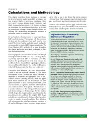
Implementing a Community<br />
Stormwater Regulation<br />
• Discuss & decide on water quality<br />
outcomes<br />
• Adopt design st<strong>and</strong>ards that achieve<br />
desired outcomes<br />
• Select stormwater methodologies to<br />
meet the design st<strong>and</strong>ards
NPDES Phase II New Stormwater<br />
Permit Requirements (rule issued<br />
May 22, 2008)<br />
• Create/enforce regulation of post-construction<br />
runoff for new <strong>and</strong> redeveloped projects >1 acre<br />
– Minimum treatment volume – one inch of runoff or<br />
runoff from 90% exceedance event<br />
– Projects must demonstrate minimum 80% TSS<br />
removal <strong>and</strong> no more than 80 mg/L leaving site<br />
– Post construction peak <strong>and</strong> total runoff = preconstruction<br />
(channel protection criteria)
LID Design Criteria<br />
• Groundwater recharge<br />
• Channel protection<br />
• Prevention of downstream flooding<br />
• Water quality protection<br />
• Evapotranspiration & the natural<br />
hydrologic/water cycle
Channel Protection Criteria<br />
• Bankfull condition responsible for<br />
shaping of channel<br />
• Match post construction runoff volume<br />
<strong>and</strong> rate to presettlement conditions up<br />
to bankfull
Channel Protection Criteria<br />
• LID site design based on no increase of<br />
presettlement runoff condition for all<br />
storms up to the 2-year, 24-hr return<br />
frequency<br />
– 95% of annual rainfall volume
Rainfall Distribution by Storm<br />
Lansing, Michigan
Waivers to Channel<br />
Protection Criteria<br />
• Waivers for certain site constraints<br />
– Poor draining soils, contaminated soils,<br />
bedrock, high water table, karst geology<br />
• Identify alternative st<strong>and</strong>ards<br />
– Detention of 1 yr, 24 hour storm <strong>and</strong> water<br />
quality criteria<br />
• Model ordinance
Flood Protection Criteria<br />
• Flood control based on local needs<br />
& flood risk<br />
• Volume runoff is maintained at<br />
presettlement value, peak rate will also be<br />
maintained up to the same storm.<br />
• Flood protection beyond presettlement<br />
value, additional control may be needed.
Flood Protection Criteria<br />
• Maintain presettlement runoff volume<br />
<strong>and</strong> rate for storms up to 2 year event.<br />
• Maintain the presettlement peak runoff<br />
rate for all storms up to the 100 year<br />
event or that determined by local<br />
st<strong>and</strong>ard.
Additional Flood Control<br />
• Many use 100 year storm<br />
• Fixed release rate<br />
• Exemptions for issues small sites or<br />
direct discharge to certain waterbodies<br />
• Model ordinance
Groundwater Recharge Criteria<br />
• Essential for providing stream flows <strong>and</strong><br />
groundwater supplies<br />
• Implement a volume control criteria <strong>and</strong><br />
maximize use of infiltration BMPs
Water Quality Criteria<br />
• Bacteria from wildlife<br />
• Nutrients from excessive fertilizer<br />
• Suspended solids from eroded<br />
streambanks, roads, & construction sites<br />
• Hydrocarbons <strong>and</strong> trace metals<br />
• Chlorides from road salt
Water Quality Criteria<br />
• Quantitative goal = 80% reduction in<br />
Total Suspended Solids based on postdevelopment<br />
l<strong>and</strong> use<br />
• Meet channel protection volume, meet<br />
water quality volume
Water Quality Criteria<br />
• Options for treatment volume<br />
– 0.5 inch of runoff<br />
– 1 inch of runoff from impervious areas &<br />
0.25 inches from disturbed pervious areas<br />
– 1 inch of runoff from disturbed pervious &<br />
impervious areas<br />
– 90% of runoff producing storms
Other Water Quality Issues<br />
• Soluble pollutants<br />
• Hot spot & high risk areas<br />
Stormwater Hot Spots<br />
Vehicle Maintenance <strong>and</strong> Repair Facilities<br />
Vehicle Fueling Stations<br />
"Fast Food" Restaurants<br />
Convenience Stores<br />
Outdoor Chemical Mixing or H<strong>and</strong>ling<br />
Outdoor Storage of Liquids<br />
Commercial Nursery Operations<br />
Other Uses or Activities Designated by Appropriate Authority<br />
Minimum Pre-Treatment Options<br />
A, E, F, G<br />
A, D, G<br />
B, C, D, I, K<br />
B, C, D, I, K<br />
G, H<br />
G<br />
I, J, L<br />
As Required
Evapotranspiration<br />
• ET is largest component of the<br />
hydrologic regime<br />
• Difficult to quantify<br />
• Minimize loss by protecting existing<br />
vegetated areas & replacing vegetation<br />
lost or removed.
Nonstructural BMPs<br />
• Protected presettlement areas are subtracted<br />
from site development for purposes of<br />
designing LID-based treatments.<br />
– Protect sensitive areas<br />
– Protect riparian buffers
Stormwater Credits<br />
• Reduces volume of runoff<br />
• Enhance the response of a piece of l<strong>and</strong><br />
to a storm event rather than treat the<br />
runoff that is generated<br />
• Based on the Curve Number method of<br />
analysis
Stormwater Credits<br />
• Credited BMPs<br />
– Minimize soil compaction<br />
– Protection of existing trees<br />
– Soil restoration<br />
– Native revegetation<br />
– Riparian buffer restoration
Example Stormwater Credits<br />
• Native revegetation/Riparian buffer<br />
restoration<br />
• Proposed trees <strong>and</strong> shrubs to be planted under the<br />
requirements of these BMPs can be assigned a<br />
Curve Number (CN) reflecting a woods in "good"<br />
condition for an area of 200 square feet per tree or<br />
the estimated tree canopy, whichever is greater. For<br />
shrubs, an area of 25 square feet per shrub.
Calculating Runoff<br />
• Runoff volume<br />
• Peak rate<br />
• Runoff Hydrograph
Runoff Volume Calculation<br />
• Various methods available<br />
– Runoff Curve Number (CN) method
Peak Rate /<br />
Hydrograph Estimations<br />
• NRCS (SCS) Unit Hydrograph Method<br />
• Modified Unit Hydrograph Method for<br />
Michigan<br />
• The Rational Method
Computer Models for<br />
Calculating Runoff<br />
• HEC Hydrologic Modeling System (HEC-<br />
HMS)<br />
• SCS/NRCS Models: WinTR-20 & WinTR-55<br />
• Stormwater Management Model (SWMM)<br />
• Source Loading <strong>and</strong> Management Model<br />
(SLAMM)<br />
• Continuous Modeling
Calculating Peak Rate By<br />
Utilizing Volume Control<br />
• Volume reduction BMPs <strong>and</strong> LID<br />
practices reduces or eliminates storage<br />
required for peak rate<br />
• Difficult to quantify peak rate benefits<br />
of LID<br />
• Milwaukee Metropolitan Sewerage District<br />
“Quicksheets”<br />
• Various other resources noted in manual
Precipitation Data<br />
• Rainfall Frequency Atlas of the Midwest<br />
– www.sws.uiuc.edu/pubdoc/B/ISWSB-<br />
71.pdf<br />
• United States Historical Climatology<br />
Network<br />
– http://cdiac.ornl.gov/epubs/ndp/ushcn/state<br />
_MI.html
Design Calculation Process<br />
Step 1: Provide general site information<br />
Step 2: Map the existing features of the site<br />
Step 3: Layout the proposed development<br />
avoiding protected areas
Design Calculation Process<br />
Step 4: Determining the disturbed area size<br />
Step 5: Calculate the level of volume control<br />
needed for channel protection
Design Calculation Process<br />
Step 6: Select volume control BMPs<br />
Step 7: Peak rate exemption for small sites<br />
Step 8: Calculate peak rate control<br />
Step 9: Determine water quality volume &<br />
select BMPs (If needed)
Step 1:<br />
Provide<br />
General Site<br />
Information
Step 2:<br />
Map<br />
Existing<br />
Features
Step 3: Layout Proposed<br />
Development<br />
• If after development is sited, addition<br />
sensitive areas are impacted, modify<br />
worksheet 2.
Step 4:<br />
Determine<br />
Disturbed<br />
Area Size
Step 5:<br />
Calculate<br />
volume<br />
control<br />
needed for<br />
channel<br />
protection
Step 6:<br />
Select<br />
volume<br />
control<br />
BMPs
Step 7:<br />
Peak Rate<br />
Exemption<br />
for Small<br />
Sites
Step 8:<br />
Calculate<br />
Peak Rate<br />
Control
Step 9:<br />
Determine<br />
Water<br />
Quality<br />
Volume<br />
(if needed)
Example for Calculating LID<br />
BMP Peak Rate Benefits<br />
• Milwaukee Metropolitan Sewage District LID<br />
“Quicksheet” (See:<br />
http://v2.mmsd.com/Assets/Documents/stormwaterweb/<br />
PDFs/Appendix_L.pdf)<br />
• Total site retention (sum of distributed BMP retention)<br />
is set as uniform depth of storage across the site<br />
• Runoff “occurs” only after runoff depth >uniform<br />
storage depth
<strong>Calculations</strong> <strong>and</strong> <strong>Methodology</strong><br />
Scott Dierks<br />
JFNew