LTC6803-2/LTC6803-4 - Multicell Battery Stack Monitor - setron
LTC6803-2/LTC6803-4 - Multicell Battery Stack Monitor - setron
LTC6803-2/LTC6803-4 - Multicell Battery Stack Monitor - setron

You also want an ePaper? Increase the reach of your titles
YUMPU automatically turns print PDFs into web optimized ePapers that Google loves.
FEATURES<br />
n Measures Up to 12 <strong>Battery</strong> Cells in Series<br />
n <strong>Stack</strong>able Architecture<br />
n Supports Multiple <strong>Battery</strong> Chemistries<br />
and Supercapacitors<br />
n Individually Addressable Serial Interface<br />
n 0.25% Maximum Total Measurement Error<br />
n Engineered for ISO26262 Compliant Systems<br />
n 13ms to Measure All Cells in a System<br />
n Passive Cell Balancing:<br />
– Integrated Cell Balancing MOSFETs<br />
– Ability to Drive External Balancing MOSFETs<br />
n Onboard Temperature Sensor and Thermistor Inputs<br />
n 1MHz Serial Interface with Packet Error Checking<br />
n Safe with Random Connection of Cells<br />
n Built-In Self Tests<br />
n Delta-Sigma Converter With Built-In Noise Filter<br />
n Open-Wire Connection Fault Detection<br />
n 12µA Standby Mode Supply Current<br />
n High EMI Immunity<br />
n 44-Lead SSOP Package<br />
APPLICATIONS<br />
n Electric and Hybrid Electric Vehicles<br />
n High Power Portable Equipment<br />
n Backup <strong>Battery</strong> Systems<br />
n Electric Bicycles, Motorcycles, Scooters<br />
<strong>LTC6803</strong>-2/<strong>LTC6803</strong>-4<br />
<strong>Multicell</strong> <strong>Battery</strong> <strong>Stack</strong><br />
<strong>Monitor</strong><br />
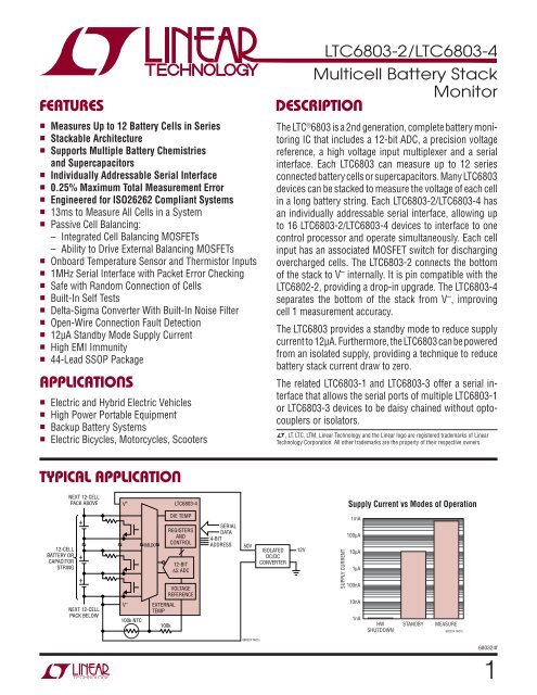
DESCRIPTION<br />
The LTC ® 6803 is a 2nd generation, complete battery monitoring<br />
IC that includes a 12-bit ADC, a precision voltage<br />
reference, a high voltage input multiplexer and a serial<br />
interface. Each <strong>LTC6803</strong> can measure up to 12 series<br />
connected battery cells or supercapacitors. Many <strong>LTC6803</strong><br />
devices can be stacked to measure the voltage of each cell<br />
in a long battery string. Each <strong>LTC6803</strong>-2/<strong>LTC6803</strong>-4 has<br />
an individually addressable serial interface, allowing up<br />
to 16 <strong>LTC6803</strong>-2/<strong>LTC6803</strong>-4 devices to interface to one<br />
control processor and operate simultaneously. Each cell<br />
input has an associated MOSFET switch for discharging<br />
overcharged cells. The <strong>LTC6803</strong>-2 connects the bottom<br />
of the stack to V – internally. It is pin compatible with the<br />
LTC6802-2, providing a drop-in upgrade. The <strong>LTC6803</strong>-4<br />
separates the bottom of the stack from V – , improving<br />
cell 1 measurement accuracy.<br />
The <strong>LTC6803</strong> provides a standby mode to reduce supply<br />
current to 12µA. Furthermore, the <strong>LTC6803</strong> can be powered<br />
from an isolated supply, providing a technique to reduce<br />
battery stack current draw to zero.<br />
The related <strong>LTC6803</strong>-1 and <strong>LTC6803</strong>-3 offer a serial interface<br />
that allows the serial ports of multiple <strong>LTC6803</strong>-1<br />
or <strong>LTC6803</strong>-3 devices to be daisy chained without optocouplers<br />
or isolators.<br />
L, LT, LTC, LTM, Linear Technology and the Linear logo are registered trademarks of Linear<br />
Technology Corporation. All other trademarks are the property of their respective owners.<br />
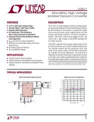
TYPICAL APPLICATION<br />
NEXT 12-CELL<br />
PACK ABOVE<br />
V +<br />
<strong>LTC6803</strong>-4<br />
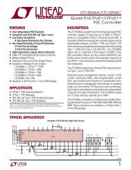
Supply Current vs Modes of Operation<br />
12-CELL<br />
BATTERY OR<br />
CAPACITOR<br />
STRING<br />
+<br />
+<br />
+<br />
NEXT 12-CELL<br />
PACK BELOW<br />
V –<br />
100k NTC<br />
MUX<br />
EXTERNAL<br />
TEMP<br />
100k<br />
DIE TEMP<br />
REGISTERS<br />
AND<br />
CONTROL<br />
12-BIT<br />
∆Σ ADC<br />
VOLTAGE<br />
REFERENCE<br />
SERIAL<br />
DATA<br />
4-BIT<br />
ADDRESS<br />
50V<br />
ISOLATED<br />
DC/DC<br />
CONVERTER<br />
12V<br />
SUPPLY CURRENT<br />
1mA<br />
100µA<br />
10µA<br />
1µA<br />
100nA<br />
10nA<br />
1nA<br />
HW<br />
SHUTDOWN<br />
STANDBY<br />
MEASURE<br />
680324 TA01b<br />
680324 TA01a<br />
680324f<br />
1
<strong>LTC6803</strong>-2/<strong>LTC6803</strong>-4<br />
ABSOLUTE MAXIMUM RATINGS<br />
Total Supply Voltage (V + to V – )..................................75V<br />
Input Voltage (Relative to V – )<br />
C0............................................................. –0.3V to 8V<br />
C12......................................................... –0.3V to 75V<br />
Cn (Note 5).......................... –0.3V to Min (8 • n, 75V)<br />
Sn (Note 5).......................... –0.3V to Min (8 • n, 75V)<br />
All Other Pins............................................ –0.3V to 7V<br />
Voltage Between Inputs<br />
Cn to Cn – 1.............................................. –0.3V to 8V<br />
Sn to Cn – 1.............................................. –0.3V to 8V<br />
C12 to C8................................................ –0.3V to 25V<br />
C8 to C4.................................................. –0.3V to 25V<br />
C4 to C0.................................................. –0.3V to 25V<br />
(Note 1)<br />
Operating Temperature Range<br />
<strong>LTC6803</strong>I..............................................–40°C to 85°C<br />
<strong>LTC6803</strong>H........................................... –40°C to 125°C<br />
Specified Temperature Range<br />
<strong>LTC6803</strong>I..............................................–40°C to 85°C<br />
<strong>LTC6803</strong>H........................................... –40°C to 125°C<br />
Junction Temperature............................................ 150°C<br />
Storage Temperature Range................... –65°C to 150°C<br />
Note: n = 1 to 12<br />
PIN CONFIGURATION<br />
<strong>LTC6803</strong>-2<br />
TOP VIEW<br />
<strong>LTC6803</strong>-4<br />
TOP VIEW<br />
V +<br />
1<br />
44<br />
CSBI<br />
V +<br />
1<br />
44<br />
CSBI<br />
C12<br />
2<br />
43<br />
SDO<br />
C12<br />
2<br />
43<br />
SDO<br />
S12<br />
3<br />
42<br />
SDI<br />
S12<br />
3<br />
42<br />
SDI<br />
C11<br />
4<br />
41<br />
SCKI<br />
C11<br />
4<br />
41<br />
SCKI<br />
S11<br />
5<br />
40<br />
A3<br />
S11<br />
5<br />
40<br />
A3<br />
C10<br />
6<br />
39<br />
A2<br />
C10<br />
6<br />
39<br />
A2<br />
S10<br />
7<br />
38<br />
A1<br />
S10<br />
7<br />
38<br />
A1<br />
C9<br />
8<br />
37<br />
A0<br />
C9<br />
8<br />
37<br />
A0<br />
S9<br />
9<br />
36<br />
GPIO2<br />
S9<br />
9<br />
36<br />
GPIO2<br />
C8<br />
10<br />
35<br />
GPIO1<br />
C8<br />
10<br />
35<br />
GPIO1<br />
S8<br />
11<br />
34<br />
WDTB<br />
S8<br />
11<br />
34<br />
WDTB<br />
C7<br />
12<br />
33<br />
NC<br />
C7<br />
12<br />
33<br />
TOS<br />
S7<br />
13<br />
32<br />
TOS<br />
S7<br />
13<br />
32<br />
V REG<br />
C6<br />
14<br />
31<br />
V REG<br />
C6<br />
14<br />
31<br />
V REF<br />
S6<br />
15<br />
30<br />
V REF<br />
S6<br />
15<br />
30<br />
V TEMP2<br />
C5<br />
16<br />
29<br />
V TEMP2<br />
C5<br />
16<br />
29<br />
V TEMP1<br />
S5<br />
C4<br />
S4<br />
17<br />
18<br />
19<br />
28<br />
27<br />
26<br />
V TEMP1<br />
NC<br />
V –<br />
S5<br />
C4<br />
S4<br />
17<br />
18<br />
19<br />
28<br />
27<br />
26<br />
NC<br />
V –<br />
C0<br />
C3<br />
20<br />
25<br />
S1<br />
C3<br />
20<br />
25<br />
S1<br />
S3<br />
21<br />
24<br />
C1<br />
S3<br />
21<br />
24<br />
C1<br />
C2<br />
22<br />
23<br />
S2<br />
C2<br />
22<br />
23<br />
S2<br />
G PACKAGE<br />
44-LEAD PLASTIC SSOP<br />
T JMAX = 150°C, θ JA = 70°C/W<br />
G PACKAGE<br />
44-LEAD PLASTIC SSOP<br />
T JMAX = 150°C, θ JA = 70°C/W<br />
2<br />
680324f
<strong>LTC6803</strong>-2/<strong>LTC6803</strong>-4<br />
ORDER INFORMATION<br />
LEAD FREE FINISH TAPE AND REEL PART MARKING* PACKAGE DESCRIPTION SPECIFIED TEMPERATURE RANGE<br />
<strong>LTC6803</strong>IG-2#PBF <strong>LTC6803</strong>IG-2#TRPBF <strong>LTC6803</strong>G-2 44-Lead Plastic SSOP –40°C to 85°C<br />
<strong>LTC6803</strong>IG-4#PBF <strong>LTC6803</strong>IG-4#TRPBF <strong>LTC6803</strong>G-4 44-Lead Plastic SSOP –40°C to 85°C<br />
<strong>LTC6803</strong>HG-2#PBF <strong>LTC6803</strong>HG-2#TRPBF <strong>LTC6803</strong>G-2 44-Lead Plastic SSOP –40°C to 125°C<br />
<strong>LTC6803</strong>HG-4#PBF <strong>LTC6803</strong>HG-4#TRPBF <strong>LTC6803</strong>G-4 44-Lead Plastic SSOP –40°C to 125°C<br />
Consult LTC Marketing for parts specified with wider operating temperature ranges. *The temperature grade is identified by a label on the shipping container.<br />
Consult LTC Marketing for information on non-standard lead based finish parts.<br />
For more information on lead free part marking, go to: http://www.linear.com/leadfree/<br />
For more information on tape and reel specifications, go to: http://www.linear.com/tapeandreel/<br />
ELECTRICAL CHARACTERISTICS The l denotes the specifications which apply over the full operating<br />
temperature range, otherwise specifications are at T A = 25°C. V + = 43.2V, V – = 0V, unless otherwise noted.<br />
SYMBOL PARAMETER CONDITIONS MIN TYP MAX UNITS<br />
DC Specifications<br />
V S Supply Voltage, V + Relative to V – V ERR Specification Met<br />
Timing Specification Met<br />
V LSB Measurement Resolution Quantization of the ADC l 1.5 mV/Bit<br />
ADC Offset (Note 2) l –0.5 0.5 mV<br />
ADC Gain Error (Note 2)<br />
l<br />
–0.12<br />
–0.22<br />
0.12<br />
0.22<br />
%<br />
%<br />
V ERR Total Measurement Error (Note4)<br />
V CELL = –0.3V<br />
V CELL = 2.3V<br />
V CELL = 2.3V<br />
V CELL = 3.6V<br />
V CELL = 3.6V, <strong>LTC6803</strong>IG<br />
V CELL = 3.6V, <strong>LTC6803</strong>HG<br />
V CELL = 4.2V<br />
V CELL = 4.2V, <strong>LTC6803</strong>IG<br />
V CELL = 4.2V, <strong>LTC6803</strong>HG<br />
V CELL = 5V<br />
2.3V < V TEMP < 4.2V, <strong>LTC6803</strong>IG<br />
2.3V < V TEMP < 4.2V, <strong>LTC6803</strong>HG<br />
V CELL Cell Voltage Range Full-Scale Voltage Range –0.3 5 V<br />
V CM Common Mode Voltage Range Range of Inputs Cn < 0.25% Gain Error,<br />
l 1.8 5 • n V<br />
Measured Relative to V –<br />
n = 2 to 11, <strong>LTC6803</strong>IG<br />
Range of Inputs C0, C1 < 0.25% Gain Error, l 0 5 V<br />
<strong>LTC6803</strong>IG<br />
Range of Inputs Cn < 0.5% Gain Error,<br />
l 1.8 5 • n V<br />
n = 2 to 11, <strong>LTC6803</strong>HG<br />
Range of Inputs C0, C1 < 0.5% Gain Error, l 0 5 V<br />
<strong>LTC6803</strong>HG<br />
Die Temperature Measurement Error Error in Measurement of 125°C 5 °C<br />
l<br />
l<br />
l<br />
l<br />
l<br />
l<br />
l<br />
l<br />
l<br />
10<br />
4<br />
–2.8<br />
–5.1<br />
–4.3<br />
–7.9<br />
–9<br />
–5<br />
–9.2<br />
–10<br />
–9.2<br />
–10<br />
±2.5<br />
±3<br />
55<br />
55<br />
2.8<br />
5.1<br />
4.3<br />
7.9<br />
9<br />
5<br />
9.2<br />
10<br />
9.2<br />
10<br />
V<br />
V<br />
mV<br />
mV<br />
mV<br />
mV<br />
mV<br />
mV<br />
mV<br />
mV<br />
mV<br />
mV<br />
mV<br />
mV<br />
680324f<br />
3
<strong>LTC6803</strong>-2/<strong>LTC6803</strong>-4<br />
ELECTRICAL CHARACTERISTICS The l denotes the specifications which apply over the full operating<br />
temperature range, otherwise specifications are at T A = 25°C. V + = 43.2V, V – = 0V, unless otherwise noted.<br />
SYMBOL PARAMETER CONDITIONS MIN TYP MAX UNITS<br />
V REF Reference Pin Voltage R LOAD = 100k to V –<br />
3.020 3.065 3.110<br />
V<br />
l 3.015 3.065 3.115<br />
V<br />
Reference Voltage Temperature<br />
8 ppm/°C<br />
Coefficient<br />
Reference Voltage Thermal Hysteresis 25°C to 85°C and 25°C to –40°C 100 ppm<br />
Reference Voltage Long-Term Drift 60 ppm/√kHr<br />
V REF2 2nd Reference Voltage<br />
V REG Regulator Pin Voltage 10V < V + < 50V, No Load<br />
I LOAD = 4mA<br />
l<br />
l<br />
l<br />
2.25<br />
2.1<br />
4.5<br />
4.5<br />
2.5<br />
2.5<br />
5.0<br />
5.0<br />
2.75<br />
2.9<br />
V<br />
V<br />
5.5 V<br />
V<br />
Regulator Pin Short-Circuit Limit l 8 mA<br />
I B Input Bias Current In/Out of Pins C1 Through C12<br />
When Measuring Cell<br />
When Not Measuring Cell<br />
I S<br />
Supply Current, Measure Mode<br />
(Note 7)<br />
Current Into the V + Pin When Measuring<br />
Continuous Measuring (CDC = 2)<br />
Continuous Measuring (CDC = 2)<br />
Measure Every 130ms (CDC = 5)<br />
Measure Every 500ms (CDC = 6)<br />
Measure Every 2 Seconds (CDC = 7)<br />
I QS Supply Current, Standby Current Into V + Pin When In Standby, All Serial<br />
Port Pin at Logic “1”<br />
<strong>LTC6803</strong>IG<br />
<strong>LTC6803</strong>HG<br />
I SD Supply Current, Hardware Shutdown Current Out of V – , V C12 = 43.2V, V + Floating<br />
(Note 8)<br />
l<br />
l<br />
l<br />
l<br />
l<br />
l<br />
–10<br />
620<br />
600<br />
190<br />
140<br />
55<br />
8<br />
6<br />
6<br />
1<br />
780<br />
780<br />
250<br />
175<br />
70<br />
12<br />
12<br />
12<br />
10 µA<br />
nA<br />
1000<br />
1150<br />
360<br />
250<br />
105<br />
16.5<br />
18<br />
19<br />
µA<br />
µA<br />
µA<br />
µA<br />
µA<br />
µA<br />
µA<br />
µA<br />
l 0.001 1 µA<br />
Discharge Switch-On Resistance V CELL > 3V (Note 3) l 10 20 Ω<br />
I OW Current Used for Open-Wire Detection l 70 110 140 µA<br />
Thermal Shutdown Temperature 145 °C<br />
Thermal Shutdown Hysteresis 5 °C<br />
Voltage Mode Timing Specifications<br />
t CYCLE Measurement Cycling Time Required to Measure 12 Cells<br />
Time Required to Measure 10 Cells<br />
Time Required to Measure 3 Temperatures<br />
Time Required to Measure 1 Cell or Temperature<br />
t 1 SDI Valid to SCKI Rising Setup l 10 ns<br />
t 2 SDI Valid to SCKI Rising Hold l 250 ns<br />
t 3 SCKI Low l 400 ns<br />
t 4 SCKI High l 400 ns<br />
t 5 CSBI Pulse Width l 400 ns<br />
t 6 CSBI Falling to SCKI Rising l 100 ns<br />
t 7 CSBI Falling to SDO Valid l 100 ns<br />
t 8 SCKI Falling to SDO Valid l 250 ns<br />
Clock Frequency l 1 MHz<br />
Watchdog Timer Timeout Period l 1 2.5 Seconds<br />
l<br />
l<br />
l<br />
l<br />
11<br />
9<br />
2.8<br />
1.0<br />
13<br />
11<br />
3.4<br />
1.2<br />
15<br />
13<br />
4.1<br />
1.4<br />
ms<br />
ms<br />
ms<br />
ms<br />
4<br />
680324f
<strong>LTC6803</strong>-2/<strong>LTC6803</strong>-4<br />
ELECTRICAL CHARACTERISTICS The l denotes the specifications which apply over the full operating<br />
temperature range, otherwise specifications are at T A = 25°C. V + = 43.2V, V – = 0V, unless otherwise noted.<br />
SYMBOL PARAMETER CONDITIONS MIN TYP MAX UNITS<br />
Voltage Mode Digital I/O<br />
V IH Digital Input Voltage High Pins SCKI, SDI and CSBI l 2 V<br />
V IL Digital Input Voltage Low Pins SCKI, SDI and CSBI l 0.8 V<br />
V OL Digital Output Voltage Low Pin SDO, Sinking 500µA l 0.3 V<br />
I IN Digital Input Current V MODE , TOS, SCKI, SDI, CSBI l 10 µA<br />
Note 1: Stresses beyond those listed under Absolute Maximum Ratings<br />
may cause permanent damage to the device. Exposure to any Absolute<br />
Maximum Rating condition for extended periods may affect device<br />
reliability and lifetime.<br />
Note 2: The ADC specifications are guaranteed by the Total Measurement<br />
Error (V ERR ) specification.<br />
Note 3: Due to the contact resistance of the production tester, this<br />
specification is tested to relaxed limits. The 20Ω limit is guaranteed by<br />
design.<br />
Note 4: V CELL refers to the voltage applied across Cn to Cn – 1 for<br />
n = 1 to 12. V TEMP refers to the voltage applied from V TEMP1 or V TEMP2<br />
to V – .<br />
Note 5: These absolute maximum ratings apply provided that the voltage<br />
between inputs do not exceed the absolute maximum ratings.<br />
Note 6: Supply current is tested during continuous measuring. The supply<br />
current during periodic measuring (130ms, 500ms, 2s) is guaranteed by<br />
design.<br />
Note 7: The CDC = 5, 6 and 7 supply currents are not measured. They are<br />
guaranteed by the CDC = 2 supply current measurement.<br />
Note 8: Limit is determined by high speed automated test capability.<br />
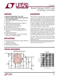
TYPICAL PERFORMANCE CHARACTERISTICS<br />
TOTAL UNADJUSTED ERROR (mV)<br />
4.5<br />
3.0<br />
1.5<br />
0<br />
–1.5<br />
–3.0<br />
Cell Measurement Error<br />
vs Cell Input Voltage<br />
T A = 125°C<br />
T A = 85°C<br />
T A = 25°C<br />
T A = –40°C<br />
–4.5<br />
0 0.5 1.0 1.5 2.0 2.5 3.0 3.5 4.0 4.5<br />
CELL INPUT VOLTAGE (V)<br />
5.0<br />
CELL VOLTAGE ERROR (mV)<br />
5<br />
0<br />
–5<br />
–10<br />
–15<br />
–20<br />
–25<br />
–30<br />
0<br />
Cell Measurement Error<br />
vs Input RC Values<br />
C = 0µF<br />
C = 0.1µF<br />
C = 1µF<br />
C = 3.3µF<br />
CELL 1, 13ms CELL MEASUREMENT<br />
REPETITION<br />
V CELL = 3.3V<br />
1 2 3 4 5 6 7 8 9 10<br />
INPUT RESISTANCE (kΩ)<br />
CELL VOLTAGE ERROR (mV)<br />
0<br />
–5<br />
–10<br />
–15<br />
–20<br />
–25<br />
–30<br />
0<br />
Cell Measurement Error<br />
vs Input RC Values<br />
C = 0µF<br />
C = 0.1µF<br />
C = 1µF<br />
C = 3.3µF<br />
CELLS 2 TO 12, 13ms CELL<br />
MEASUREMENT REPETITION<br />
V CELL = 3.3V<br />
1 2 3 4 5 6 7 8 9 10<br />
INPUT RESISTANCE (kΩ)<br />
680324 G01<br />
680324 G02<br />
680324 G03<br />
680324f<br />
5
<strong>LTC6803</strong>-2/<strong>LTC6803</strong>-4<br />
TYPICAL PERFORMANCE CHARACTERISTICS<br />
CELL 12 MEASUREMENT ERROR (mV)<br />
100<br />
10<br />
1<br />
Cell 12 Measurement Error vs V +<br />
T A = 25°C<br />
V CELL = 3.3V<br />
0.1<br />
–0.8 –0.6 –0.4 –0.2 0 0.2 0.4 0.6 0.8 1.0<br />
V + – V C12 (V)<br />
680324 G04<br />
CELL MEASUREMENT ERROR (mV)<br />
2<br />
0<br />
–2<br />
–4<br />
–6<br />
–8<br />
–10<br />
–12<br />
–14<br />
0<br />
Cell Voltage Measurement Error<br />
vs Common Mode Voltage<br />
V CELL = 3.6V<br />
T A = 25°C<br />
CELL2 ERROR vs V C1<br />
CELL3 ERROR vs V C2<br />
CELLn ERROR VS V Cn–1 ,<br />
n = 4 TO 12<br />
1 2 3 4 5<br />
COMMON MODE VOLTAGE (V)<br />
680324 G05<br />
CELL VOLTAGE MEASUREMENT ERROR (mV)<br />
1000<br />
100<br />
10<br />
1<br />
Cell Measurement Error<br />
vs Cell Voltage<br />
ALL OTHER CELLS = 3V<br />
CELL6<br />
0.1<br />
–1.0 –0.8 –0.6 –0.4 –0.2 0 0.2 0.4 0.6 0.8 1.0<br />
V IN CELL6 (V)<br />
680324 G06<br />
CELL MEASUREMENT ERROR (mV)<br />
1.75<br />
1.00<br />
0.25<br />
–0.50<br />
–1.25<br />
–2.00<br />
–50<br />
Cell 1 Voltage Measurement Error<br />
vs Temperature<br />
V CELL = 0.8V<br />
V + = 9.6V<br />
4 SAMPLES<br />
–30 –10 10 30 50 70 90 110 130<br />
TEMPERATURE (°C)<br />
680324 G07<br />
CELL MEASUREMENT ERROR (mV)<br />
2.50<br />
1.75<br />
1.00<br />
0.25<br />
–0.50<br />
–1.25<br />
–2.00<br />
–50<br />
Cell 2 Voltage Measurement Error<br />
vs Temperature<br />
V CELL = 0.8V<br />
V + = 9.6V<br />
4 SAMPLES<br />
–30 –10 10 30 50 70 90 110 130<br />
TEMPERATURE (°C)<br />
680324 G08<br />
CELL MEASUREMENT ERROR (mV)<br />
1.75<br />
1.00<br />
0.25<br />
–0.50<br />
Cell 3 to Cell 12 Voltage<br />
Measurement Error vs Temperature<br />
–1.25 V CELL = 0.8V<br />
V + = 9.6V<br />
4 SAMPLES<br />
–2.00<br />
–50 –30 –10 10 30 50 70 90 110 130<br />
TEMPERATURE (°C)<br />
680324 G09<br />
NUMBER OF UNITS<br />
25<br />
20<br />
15<br />
10<br />
5<br />
Measurement Gain Error<br />
Hysteresis<br />
T A = 85°C TO 25°C<br />
0<br />
–250–200–150–100 –50 0 50 100 150 200<br />
CHANGE IN GAIN ERROR (ppm)<br />
680324 G10<br />
NUMBER OF UNITS<br />
20<br />
18<br />
16<br />
14<br />
12<br />
10<br />
8<br />
6<br />
4<br />
2<br />
Measurement Gain Error<br />
Hysteresis<br />
T A = –45°C TO 25°C<br />
0<br />
–250–200–150–100 –50 0 50 100 150 200<br />
CHANGE IN GAIN ERROR (ppm)<br />
680324 G11<br />
REJECTION (dB)<br />
0<br />
–10<br />
–20<br />
–30<br />
–40<br />
–50<br />
–60<br />
Cell Measurement Common Mode<br />
Rejection<br />
V CM(IN) = 5V P-P<br />
72dB REJECTION<br />
CORRESPONDS TO<br />
LESS THAN 1 BIT<br />
AT ADC OUTPUT<br />
–70<br />
10 100 1k 10k 100k 1M 10M<br />
FREQUENCY (Hz)<br />
680324 G12<br />
6<br />
680324f
TYPICAL PERFORMANCE CHARACTERISTICS<br />
<strong>LTC6803</strong>-2/<strong>LTC6803</strong>-4<br />
0<br />
ADC Normal Mode Rejection<br />
vs Frequency<br />
2.0<br />
ADC INL<br />
1.0<br />
ADC DNL<br />
REJECTION (dB)<br />
–10<br />
–20<br />
–30<br />
–40<br />
–50<br />
–60<br />
INL (BITS)<br />
1.5<br />
1.0<br />
0.5<br />
0<br />
–0.5<br />
–1.0<br />
–1.5<br />
DNL (BITS)<br />
0.8<br />
0.6<br />
0.4<br />
0.2<br />
0<br />
–0.2<br />
–0.4<br />
–0.6<br />
–0.8<br />
–70<br />
10 100 1k 10k 100k<br />
FREQUENCY (Hz)<br />
680324 G13<br />
–2.0<br />
0<br />
1 2 3 4<br />
INPUT (V)<br />
5<br />
680324 G14<br />
–1.0<br />
0<br />
1 2 3 4<br />
INPUT (V)<br />
5<br />
680324 G15<br />
CELL INPUT BIAS CURRENT (nA)<br />
50<br />
45<br />
40<br />
35<br />
30<br />
25<br />
20<br />
15<br />
10<br />
5<br />
0<br />
–40<br />
Cell Input Bias Current During<br />
Standby and Hardware Shutdown<br />
CELL INPUT = 3.6V<br />
C12<br />
C1<br />
C6<br />
–20 0 20 40 60 80 100 120<br />
TEMPERATURE (°C)<br />
SUPPLY CURRENT (µA)<br />
16<br />
14<br />
12<br />
10<br />
8<br />
6<br />
4<br />
2<br />
0<br />
0<br />
Standby Supply Current<br />
vs Supply Voltage<br />
10 20 30 40 50<br />
SUPPLY VOLTAGE (V)<br />
125°C<br />
85°C<br />
25°C<br />
–40°C<br />
60<br />
SUPPLY CURRENT (µA)<br />
850<br />
800<br />
750<br />
7000<br />
650<br />
600<br />
0<br />
Supply Current vs Supply Voltage<br />
During Continuous Conversions<br />
CDC = 2<br />
CONTINUOUS CONVERSION<br />
10 20 30 40 50<br />
SUPPLY VOLTAGE (V)<br />
125°C<br />
85°C<br />
25°C<br />
–40°C<br />
60<br />
680324 G16<br />
680324 G17<br />
680324 G18<br />
E = (AMBIENT TEMP-INTERNAL<br />
DIE TEMP READING) (°C)<br />
15<br />
10<br />
5<br />
0<br />
–5<br />
Internal Die Temperature<br />
Measurement Error Using an<br />
8mV/°K Scale Factor<br />
10 SAMPLES<br />
TOTAL UNADJUSTED ERROR (mV)<br />
4.5<br />
3.0<br />
1.5<br />
0<br />
–1.5<br />
–3.0<br />
External Temperature<br />
Measurement Total Unadjusted<br />
Error vs Input<br />
T A = 125°C<br />
T A = 85°C<br />
T A = 25°C<br />
T A = –40°C<br />
–10<br />
0<br />
25 50 75 100<br />
TEMPERATURE (°C)<br />
125 150<br />
–4.5<br />
0 0.5 1.0 1.5 2.0 2.5 3.0 3.5 4.0 4.5<br />
TEMPERATURE INPUT VOLTAGE (V)<br />
5.0<br />
680324 G19<br />
680324 G20<br />
680324f<br />
7
<strong>LTC6803</strong>-2/<strong>LTC6803</strong>-4<br />
TYPICAL PERFORMANCE CHARACTERISTICS<br />
V REF (V)<br />
3.070<br />
3.068<br />
3.066<br />
3.064<br />
3.062<br />
3.060<br />
3.058<br />
V REF Output Voltage<br />
vs Temperature<br />
5 REPRESENTATIVE UNITS<br />
3.056<br />
–50 –25 0 25 50 75 100<br />
TEMPERATURE (°C)<br />
125<br />
680324 G21<br />
V REF (V)<br />
3.09<br />
3.08<br />
3.07<br />
3.06<br />
3.05<br />
3.04<br />
0<br />
V REF Load Regulation<br />
T A = 85°C<br />
T A = –40°C<br />
10 100<br />
SOURCING CURRENT (µA)<br />
T A = 25°C<br />
1000<br />
680324 G22<br />
V REF (V)<br />
3.074<br />
3.072<br />
3.070<br />
3.068<br />
3.066<br />
3.064<br />
3.062<br />
3.060<br />
0<br />
V REF Line Regulation<br />
NO EXTERNAL LOAD ON V REF , CDC = 2<br />
(CONTINUOUS CELL CONVERSIONS)<br />
T A = 25°C<br />
T A = 85°C<br />
T A = –40°C<br />
10 20 30 40 50<br />
SUPPLY VOLTAGE (V)<br />
60<br />
680324 G23<br />
V REG (V)<br />
5.2<br />
5.0<br />
4.8<br />
4.6<br />
4.4<br />
4.2<br />
4.0<br />
0<br />
V REG Load Regulation<br />
V + = 43.2V<br />
T A = 125°C<br />
T A = 85°C<br />
T A = 25°C<br />
T A = –40°C<br />
2 4 6 8<br />
SUPPLY CURRENT (mA)<br />
10 12<br />
680324 G24<br />
V REG (V)<br />
5.5<br />
5.0<br />
4.5<br />
4.0<br />
0<br />
V REG Line Regulation<br />
CDC = 2<br />
CONTINUOUS CONVERSIONS<br />
10 20 30 40<br />
SUPPLY VOLTAGE (V)<br />
T A = 125°C<br />
T A = 85°C<br />
T A = 25°C<br />
T A = –40°C<br />
50 60<br />
680324 G25<br />
DISCHARGE RESISTANCE (Ω)<br />
50<br />
45<br />
40<br />
35<br />
30<br />
25<br />
20<br />
15<br />
10<br />
5<br />
0<br />
0<br />
Internal Discharge Resistance<br />
vs Cell Voltage<br />
T A = 105°C<br />
T A = 85°C<br />
T A = 25°C<br />
T A = –45°C<br />
0.5 1.0 1.5 2.0 2.5 3.0 3.5 4.0 4.5 5.0<br />
CELL VOLTAGE (V)<br />
680324 G26<br />
INCREASE IN DIE TEMPERATURE (°C)<br />
50<br />
45<br />
40<br />
35<br />
30<br />
25<br />
20<br />
15<br />
10<br />
5<br />
0<br />
0<br />
Die Temperature Increase vs<br />
Discharge Current in Internal FET<br />
ALL 12 CELLS AT 3.6V<br />
V S = 43.2V<br />
T A = 25°C<br />
12 CELLS<br />
DISCHARGING<br />
6 CELLS<br />
DISCHARGING<br />
1 CELL<br />
DISCHARGING<br />
10 20 30 40 50 60 70 80<br />
DISCHARGE CURRENT PER CELL (mA)<br />
680324 G27<br />
CONVERSION TIME (ms)<br />
Cell Conversion Time<br />
13.20<br />
13.15<br />
13.10<br />
13.05<br />
13.00<br />
12.95<br />
12.90<br />
12.85<br />
12.80<br />
–40 –20 0 20 40 60 80 100 120<br />
TEMPERATURE (°C)<br />
680324 G28<br />
8<br />
680324f
PIN FUNCTIONS<br />
To ensure pin compatibility with LTC6802-2, the <strong>LTC6803</strong>‐2<br />
is configured such that the bottom cell input (C0) is connected<br />
internally to the negative supply voltage (V – ). The<br />
<strong>LTC6803</strong>-4 offers a unique pinout with an input for the<br />
bottom cell (C0). This simple functional difference offers<br />
the possibility for enhanced cell 1 measurement accuracy,<br />
enhanced SPI noise tolerance and simplified wiring. More<br />
information is provided in the Applications Information<br />
section entitled Advantages of Kelvin Connection for C0.<br />
V + (Pin 1): Positive Power Supply. Pin 1 can be tied to the<br />
most positive potential in the battery stack or an isolated<br />
power supply. V + must be greater than the most positive<br />
potential in the battery stack under normal operation. With<br />
an isolated power supply, <strong>LTC6803</strong> can be turned off by<br />
simply shutting down V + .<br />
C12, C11, C10, C9, C8, C7, C6, C5, C4, C3, C2, C1<br />
(Pins 2, 4, 6, 8, 10, 12, 14, 16, 18, 20, 22, 24): C1<br />
through C12 are the inputs for monitoring battery cell<br />
voltages. The negative terminal of the bottom cell should<br />
be tied to the V – pin for the <strong>LTC6803</strong>-2, and the C0 pin for<br />
the <strong>LTC6803</strong>-4. The next lowest potential is tied to C1 and<br />
so forth. See the figures in the Applications Information<br />
section for more details on connecting batteries to the<br />
<strong>LTC6803</strong>-2 and <strong>LTC6803</strong>-4. The <strong>LTC6803</strong> can monitor a<br />
series connection of up to 12 cells. Each cell in a series<br />
connection must have a common mode voltage that is<br />
greater than or equal to the cells below it. 100mV negative<br />
voltages are permitted.<br />
C0 (Pin 26 on <strong>LTC6803</strong>-4): Negative Terminal of the Bottom<br />
<strong>Battery</strong> Cell. C0 and V – form a Kelvin connection to<br />
eliminate effect of voltage drop at the V – trace.<br />
S12, S11, S10, S9, S8, S7, S6, S5, S4, S3, S2, S1 (Pins<br />
3, 5, 7, 9, 11, 13, 15, 17, 19, 21, 23, 25): S1 though<br />
S12 pins are used to balance battery cells. If one cell in a<br />
series becomes overcharged, an S output can be used to<br />
discharge the cell. Each S output has an internal N-channel<br />
MOSFET for discharging. See the Block Diagram. The NMOS<br />
has a maximum on-resistance of 20Ω. An external resistor<br />
<strong>LTC6803</strong>-2/<strong>LTC6803</strong>-4<br />
should be connected in series with the NMOS to dissipate<br />
heat outside of the <strong>LTC6803</strong> package. When using the<br />
internal MOSFETs to discharge cells, the die temperature<br />
should be monitored. See Power Dissipation and Thermal<br />
Shutdown in the Applications Information section. The S<br />
pins also feature an internal pull-up PMOS. This allows the<br />
S pins to be used to drive the gates of external MOSFETs<br />
for higher discharge capability.<br />
V – (Pin 26 on <strong>LTC6803</strong>-2/Pin 27 on <strong>LTC6803</strong>-4): Connect<br />
V – to the most negative potential in the series of cells.<br />
NC (Pin 27 on <strong>LTC6803</strong>-2/Pin 28 on <strong>LTC6803</strong>-4): This pin<br />
is not used and is internally connected to V – through 10Ω.<br />
It can be left unconnected or connected to V – on the PCB.<br />
V TEMP1 , V TEMP2 (Pins 28, 29 on <strong>LTC6803</strong>-2/Pins 29, 30,<br />
on <strong>LTC6803</strong>-4): Temperature Sensor Inputs. The ADC will<br />
measure the voltage on V TEMPn with respect to V – and store<br />
the result in the TMP register. The ADC measurements<br />
are relative to the V REF pin voltage. Therefore a simple<br />
thermistor and resistor combination connected to the<br />
V REF pin can be used to monitor temperature. The V TEMP<br />
inputs can also be general purpose ADC inputs.<br />
V REF (Pin 30 on <strong>LTC6803</strong>-2/Pin 31 on <strong>LTC6803</strong>-4): 3.065V<br />
Voltage Reference Output. This pin should be bypassed<br />
with a 1µF capacitor. The V REF pin can drive a 100k resistive<br />
load connected to V – . Larger loads should be buffered<br />
with an LT6003 op amp, or a similar device.<br />
V REG (Pin 31 on <strong>LTC6803</strong>-2/Pin 32 on <strong>LTC6803</strong>-4): Linear<br />
Voltage Regulator Output. This pin should be bypassed with<br />
a 1µF capacitor. The V REG is capable of sourcing up to 4mA<br />
to an external load. The V REG pin does not sink current.<br />
TOS (Pin 32 on <strong>LTC6803</strong>-2/Pin 33 on <strong>LTC6803</strong>-4): Top<br />
of <strong>Stack</strong> Input. The TOS pin can be tied to V REG or V – for<br />
the <strong>LTC6803</strong>. The state of the TOS pin alters the operation<br />
of the SDO pin in the toggle polling mode. See the Serial<br />
Port description.<br />
NC (Pin 33 on <strong>LTC6803</strong>-2): No Connection.<br />
680324f<br />
9
<strong>LTC6803</strong>-2/<strong>LTC6803</strong>-4<br />
PIN FUNCTIONS<br />
WDTB (Pin 34): Watchdog Timer Output (Active Low). If<br />
there is no valid command received in 1 to 2.5 seconds, the<br />
WDTB output is asserted. The WDTB pin is an open-drain<br />
NMOS output. When asserted it pulls the output down to<br />
V – and resets the configuration register to its default state.<br />
GPIO1, GPIO2 (Pins 35, 36): General Purpose Input/<br />
Output. By writing a “0” to a GPIO configuration register<br />
bit, the open-drain output is activated and the pin is pulled<br />
to V – . By writing a logic “1” to the configuration register<br />
bit, the corresponding GPIO pin is high impedance. An<br />
external resistor is required to pull the pin up to V REG .<br />
By reading the configuration register locations GPIO1<br />
and GPIO2, the state of the pins can be determined. For<br />
example, if a “0” is written to register bit GPIO1, a “0” is<br />
always read back because the output N-channel MOSFET<br />
pulls Pin 35 to V – . If a “1” is written to register bit GPIO1,<br />
the pin becomes high impedance. Either a “1” or a “0” is<br />
read back, depending on the voltage present at Pin 35.<br />
The GPIOs makes it possible to turn-on/off circuitry around<br />
the <strong>LTC6803</strong>-4, or read logic values from a circuit around<br />
the <strong>LTC6803</strong>-4. The GPIO pins should be connected to<br />
V – if not used.<br />
A0, A1, A2, A3 (Pins 37, 38, 39, 40): Address Inputs.<br />
These pins are tied to V REG or V – . The state of the address<br />
pins (V REG = 1, V – = 0) determines the <strong>LTC6803</strong> address.<br />
See Address Commands in the Serial Port subsection of<br />
the Applications Information section.<br />
SCKI (Pin 41): Serial Clock Input. The SCKI pin interfaces<br />
to any logic gate (TTL levels). See Serial Port in the<br />
Applications Information section.<br />
SDI (Pin 42): Serial Data Input. The SDI pin interfaces to<br />
any logic gate (TTL levels). See Serial Port in the Applications<br />
Information section.<br />
SDO (Pin 43): Serial Data Output. The SDO pin is an NMOS<br />
open-drain output. A pull-up resistor is needed on SDO.<br />
See Serial Port in the Applications Information section.<br />
CSBI (Pin 44): Chip Select (Active Low) Input. The CSBI<br />
pin interfaces to any logic gate (TTL levels). See Serial<br />
Port in the Applications Information section.<br />
10<br />
680324f
BLOCK DIAGRAMS<br />
<strong>LTC6803</strong>-2/<strong>LTC6803</strong>-4<br />
2<br />
<strong>LTC6803</strong>-2<br />
C12<br />
2nd REFERENCE<br />
V REF2<br />
1<br />
V +<br />
REGULATOR<br />
V REG<br />
31<br />
3<br />
S12<br />
WATCHDOG<br />
TIMER<br />
WDTB<br />
34<br />
4<br />
C11<br />
21 S3<br />
22<br />
C2<br />
MUX<br />
25 S1<br />
23 S2<br />
24 C1<br />
∆Σ A/D<br />
CONVERTER<br />
REFERENCE<br />
12<br />
RESULTS<br />
REGISTER<br />
AND<br />
COMMUNICATIONS<br />
A3<br />
40<br />
A2<br />
39<br />
A1<br />
38<br />
A0<br />
37<br />
CSBI<br />
44<br />
SDO 43<br />
SDI<br />
42<br />
SCKI<br />
41<br />
GPIO2<br />
39<br />
26 V– 27 28<br />
CONTROL<br />
GPIO1<br />
38<br />
NC<br />
DIE<br />
TEMP<br />
EXTERNAL<br />
TEMP<br />
V TEMP1 V TEMP2<br />
29<br />
V REF<br />
30<br />
TOS<br />
32<br />
68032 BD<br />
680324f<br />
11
<strong>LTC6803</strong>-2/<strong>LTC6803</strong>-4<br />
BLOCK DIAGRAMS<br />
<strong>LTC6803</strong>-4<br />
1<br />
V +<br />
2nd REFERENCE<br />
V REF2<br />
REGULATOR<br />
V REG<br />
32<br />
2<br />
C12<br />
3<br />
S12<br />
WATCHDOG<br />
TIMER<br />
WDTB<br />
34<br />
4<br />
C11<br />
21 S3<br />
22<br />
C2<br />
MUX<br />
25 S1<br />
23 S2<br />
24 C1<br />
∆Σ A/D<br />
CONVERTER<br />
REFERENCE<br />
12<br />
RESULTS<br />
REGISTER<br />
AND<br />
COMMUNICATIONS<br />
A3<br />
A2<br />
A1<br />
A0<br />
CSBI<br />
SDO<br />
SDI<br />
SCKI<br />
GPIO2<br />
40<br />
39<br />
38<br />
37<br />
44<br />
43<br />
42<br />
41<br />
36<br />
26 C0<br />
CONTROL<br />
GPIO1<br />
35<br />
27<br />
V –<br />
DIE<br />
TEMP<br />
EXTERNAL<br />
TEMP<br />
TOS<br />
33<br />
NC<br />
V TEMP1<br />
V TEMP2<br />
V REF<br />
28<br />
29<br />
30<br />
31<br />
68033 BD<br />
TIMING DIAGRAM<br />
Timing Diagram of the Serial Interface<br />
t 1<br />
t 8<br />
t 4 t 6<br />
t 3<br />
t 5<br />
t 7<br />
t 2<br />
SCKI<br />
SDI<br />
D3 D2 D1 D0 D7···D4 D3<br />
CSBI<br />
SDO D4 D3 D2 D1 D0 D7···D4 D3<br />
PREVIOUS<br />
COMMAND<br />
CURRENT<br />
COMMAND<br />
68034 TD<br />
12<br />
680324f
OPERATION<br />
THEORY OF OPERATION<br />
The <strong>LTC6803</strong> is a data acquisition IC capable of measuring<br />
the voltage of 12 series connected battery cells.<br />
An input multiplexer connects the batteries to a 12-bit<br />
delta-sigma analog-to-digital converter (ADC). An internal<br />
8ppm/°C voltage reference combined with the ADC give<br />
the <strong>LTC6803</strong> its outstanding measurement accuracy. The<br />
inherent benefits of the delta-sigma ADC versus other types<br />
of ADCs (e.g., successive approximation) are explained<br />
in Advantages of Delta-Sigma ADCs in the Applications<br />
Information section.<br />
Communication between the <strong>LTC6803</strong> and a host processor<br />
is handled by a SPI compatible serial interface. Multiple<br />
<strong>LTC6803</strong>s can be connected to a single serial interface.<br />
As shown in Figure 1, the <strong>LTC6803</strong>-2s or <strong>LTC6803</strong>-4s<br />
are isolated from one another using digital isolators. A<br />
unique addressing scheme allows all the <strong>LTC6803</strong>-2s or<br />
<strong>LTC6803</strong>‐4s to connect to the same serial port of the host<br />
processor. Further explanation of the <strong>LTC6803</strong>-2/<strong>LTC6803</strong>-<br />
4 can be found in the Serial Port section of the data sheet.<br />
The <strong>LTC6803</strong> also contains circuitry to balance cell voltages.<br />
Internal MOSFETs can be used to discharge cells. These<br />
internal MOSFETs can also be used to control external<br />
balancing circuits. Figure 1 illustrates cell balancing by<br />
internal discharge. Figure 3 shows the S pin controlling<br />
an external balancing circuit. It is important to note that<br />
the <strong>LTC6803</strong> makes no decisions about turning on/off<br />
the internal MOSFETs. This is completely controlled by<br />
the host processor. The host processor writes values to<br />
a configuration register inside the <strong>LTC6803</strong> to control the<br />
switches. The watchdog timer on the <strong>LTC6803</strong> can be used<br />
to turn off the discharge switches if communication with<br />
the host processor is interrupted.<br />
Since the <strong>LTC6803</strong>-4 separates C0 and V – , C0 can have<br />
higher potential than V – . This feature is very useful for<br />
super capacitors and fuel cells whose voltages can go to<br />
zero or slightly negative. In such a case, the stacked cells<br />
can’t power the <strong>LTC6803</strong>-4. In Figure 1, an isolated 36V<br />
and –3.6V provides power to each <strong>LTC6803</strong>-4. This allows<br />
the C1 to C12 pins to go up to 3.6V below C0.<br />
<strong>LTC6803</strong>-2/<strong>LTC6803</strong>-4<br />
The <strong>LTC6803</strong> has three modes of operation: hardware<br />
shutdown, standby and measure. Hardware shutdown is<br />
a true zero power mode. Standby mode is a power saving<br />
state where all circuits except the serial interface are turned<br />
off. In measure mode, the <strong>LTC6803</strong> is used to measure<br />
cell voltages and store the results in memory. Measure<br />
mode will also monitor each cell voltage for overvoltage<br />
(OV) and undervoltage (UV) conditions.<br />
HARDWARE SHUTDOWN MODE<br />
The V + pin can be disconnected from the C pins and the<br />
battery pack. If the V + supply pin is 0V, the <strong>LTC6803</strong> will<br />
typically draw less than 1nA from the battery cells. All<br />
circuits inside the IC are off. It is not possible to communicate<br />
with the IC when V + = 0V. See the Applications<br />
Information section for hardware shutdown circuits.<br />
STANDBY MODE<br />
The <strong>LTC6803</strong> defaults (powers up) to standby mode.<br />
Standby mode is the lowest supply current state with a<br />
supply connected. Standby current is typically 12µA when<br />
V + = 44V. All circuits are turned off except the serial interface<br />
and the voltage regulator. For the lowest possible standby<br />
current consumption, all SPI logic inputs should be set to<br />
logic 1 level. The <strong>LTC6803</strong> can be programmed for standby<br />
mode by setting the comparator duty cycle configuration<br />
bits, CDC[2:0], to 0. If the part is put into standby mode<br />
while ADC measurements are in progress, the measurements<br />
will be interrupted and the cell voltage registers will<br />
be in an indeterminate state. To exit standby mode, the CDC<br />
bits must be written to a value other than 0.<br />
MEASURE MODE<br />
The <strong>LTC6803</strong> is in measure mode when the CDC bits are<br />
programmed with a value from 1 to 7. When CDC = 1 the<br />
<strong>LTC6803</strong> is on and waiting for a start ADC conversion<br />
command. When CDC is 2 through 7 the IC monitors each<br />
cell voltage and produces an interrupt signal on the SDO<br />
pin indicating all cell voltages are within the UV and OV<br />
limits. The value of the CDC bits determines how often<br />
the cells are monitored, and, how much average supply<br />
current is consumed.<br />
680324f<br />
13
<strong>LTC6803</strong>-2/<strong>LTC6803</strong>-4<br />
OPERATION<br />
+<br />
+<br />
+<br />
+<br />
+<br />
+<br />
+<br />
+<br />
+<br />
+<br />
+<br />
V +<br />
C12<br />
S12<br />
C11<br />
S11<br />
C10<br />
S10<br />
C9<br />
S9<br />
C8<br />
S8<br />
C7<br />
S7<br />
C6<br />
S6<br />
C5<br />
S5<br />
C4<br />
S4<br />
C3<br />
S3<br />
C2<br />
<strong>LTC6803</strong>-4<br />
IC #1<br />
CSBI<br />
SDO<br />
SDI<br />
SCKI<br />
A3<br />
A2<br />
A1<br />
A0<br />
GPIO2<br />
GPIO1<br />
WDTB<br />
TOS<br />
V REG<br />
V REF<br />
V TEMP2<br />
V TEMP1<br />
NC<br />
V –<br />
C0<br />
S1<br />
C1<br />
S2<br />
ADDRESS1<br />
V2 –<br />
OE2<br />
V1 –<br />
OE1<br />
V2 – V1 –<br />
V2 + V1 +<br />
DIGITAL<br />
ISOLATOR<br />
ISOLATED<br />
DC/DC<br />
CONVERTER<br />
3V<br />
12V<br />
+<br />
+<br />
+<br />
+<br />
+<br />
+<br />
+<br />
+<br />
+<br />
+<br />
+<br />
+<br />
V +<br />
C12<br />
S12<br />
C11<br />
S11<br />
C10<br />
S10<br />
C9<br />
S9<br />
C8<br />
S8<br />
C7<br />
S7<br />
C6<br />
S6<br />
C5<br />
S5<br />
C4<br />
S4<br />
C3<br />
S3<br />
C2<br />
<strong>LTC6803</strong>-4<br />
IC #7<br />
CSBI<br />
SDO<br />
SDI<br />
SCKI<br />
A3<br />
A2<br />
A1<br />
A0<br />
GPIO2<br />
GPIO1<br />
WDTB<br />
TOS<br />
V REG<br />
V REF<br />
V TEMP2<br />
V TEMP1<br />
NC<br />
V –<br />
C0<br />
S1<br />
C1<br />
S2<br />
ADDRESS7<br />
V2 –<br />
OE2<br />
V1 –<br />
OE1<br />
V2 – V1 –<br />
V2 + V1 +<br />
DIGITAL<br />
ISOLATOR<br />
ISOLATED<br />
DC/DC<br />
CONVERTER<br />
3V<br />
12V<br />
680324 F01<br />
3V<br />
+<br />
+<br />
+<br />
+<br />
+<br />
+<br />
+<br />
+<br />
+<br />
+<br />
+<br />
V +<br />
C12<br />
S12<br />
C11<br />
S11<br />
C10<br />
S10<br />
C9<br />
S9<br />
C8<br />
S8<br />
C7<br />
S7<br />
C6<br />
S6<br />
C5<br />
S5<br />
C4<br />
S4<br />
C3<br />
S3<br />
C2<br />
<strong>LTC6803</strong>-4<br />
IC #0<br />
CSBI<br />
SDO<br />
SDI<br />
SCKI<br />
A3<br />
A2<br />
A1<br />
A0<br />
GPIO2<br />
GPIO1<br />
WDTB<br />
TOS<br />
V REG<br />
V REF<br />
V TEMP2<br />
V TEMP1<br />
NC<br />
V –<br />
C0<br />
S1<br />
C1<br />
S2<br />
ADDRESS0<br />
V2 –<br />
OE2<br />
V1 –<br />
OE1<br />
V2 – V1 –<br />
V2 + V1 +<br />
DIGITAL<br />
ISOLATOR<br />
ISOLATED<br />
DC/DC<br />
CONVERTER<br />
3V<br />
12V<br />
MPU<br />
MISO<br />
CS<br />
M0SI<br />
CLK<br />
MODULE<br />
IO<br />
+<br />
Figure 1. Simplified 96-Cell <strong>Battery</strong> or Supercapacitor, Isolated Interface. In this Diagram the <strong>Battery</strong><br />
Negative is Isolated from the Module Ground. Isolated Power Supplies Each <strong>LTC6803</strong>-4. Opto-Couplers<br />
or Digital Isolators Allow Each IC to Be Addressed Individually<br />
14<br />
680324f
OPERATION<br />
There are two methods for indicating the UV/OV interrupt<br />
status: toggle polling (using a 1kHz output signal)<br />
and level polling (using a high or low output signal). The<br />
polling methods are described in the Serial Port section.<br />
The UV/OV limits are set by the V UV and V OV values in the<br />
configuration registers. When a cell voltage exceeds the<br />
UV/OV limits a bit is set in the flag register. The UV and<br />
OV flag status for each cell can be determined using the<br />
Read Flag Register Group.<br />
An ADC measurement can be requested at any time when<br />
the IC is in measure mode. To initiate cell voltage measurements<br />
while in measure mode, a Start A/D Conversion<br />
command is sent. After the command has been sent, the<br />
<strong>LTC6803</strong> will indicate the A/D converter status via toggle<br />
polling or level polling (as described in the Serial Port<br />
section). During cell voltage measurement commands,<br />
the UV and OV flags (within the flag register group) are<br />
also updated. When the measurements are complete, the<br />
part will continue monitoring UV and OV conditions at the<br />
rate designated by the CDC bits.<br />
Operating with Less than 12 Cells<br />
If fewer than 12 cells are connected to the <strong>LTC6803</strong>, the<br />
unused input channels must be masked. The MCxI bits in<br />
the configuration registers are used to mask channels. In<br />
addition, the <strong>LTC6803</strong> can be configured to automatically<br />
bypass the measurements of the top 2 cells, reducing power<br />
consumption and measurement time. If the CELL10 bit is<br />
high, the inputs for cell 11 and cell 12 are masked and only<br />
the bottom 10-cell voltages will be measured. By default,<br />
the CELL10 bit is low, enabling measurement of all 12-cell<br />
voltages. Additional information regarding operation with<br />
less than 12 cells is provided in the applications section.<br />
ADC RANGE AND OUTPUT FORMAT<br />
The ADC outputs a 12-bit code with an offset of 0x200<br />
(512 decimal). The input voltage can be calculated as:<br />
V IN = (DOUT – 512) • V LSB ; V LSB = 1.5mV<br />
where DOUT is a decimal integer.<br />
For example, a 0V input will have an output reading of 0x200.<br />
An ADC reading of 0x000 means the input was –0.768V. The<br />
<strong>LTC6803</strong>-2/<strong>LTC6803</strong>-4<br />
absolute ADC measurement range is –0.768V to 5.376V.<br />
The resolution is V LSB = 1.5mV = (5.376 + 0.768)/2 12 . The<br />
useful range is –0.3V to 5V. This range allows monitoring<br />
supercapacitors which could have small negative voltage.<br />
Inputs below –0.3V exceed the absolute maximum rating<br />
of the C pins. If all inputs are negative, the ADC range is<br />
reduced to –0.1V. Inputs above 5V will have noisy ADC<br />
readings (see Typical Performance Characteristics).<br />
ADC MEASUREMENTS DURING CELL BALANCING<br />
The primary cell voltage ADC measurement commands<br />
(STCVAD and STOWAD) automatically turn off a cell’s<br />
discharge switch while its voltage is being measured. The<br />
discharge switches for the cell above and the cell below will<br />
also be turned off during the measurement. For example,<br />
discharge switches S4, S5 and S6 will be off while cell 5<br />
is being measured.<br />
In some systems it may be desirable to allow discharging to<br />
continue during cell voltage measurements. The cell voltage<br />
ADC conversion commands STCVDC and STOWDC allow<br />
the discharge switches to remain on during cell voltage<br />
measurements. This feature allows the system to perform<br />
a self test to verify the discharge functionality.<br />
All discharge switches are automatically disabled during<br />
OV and UV comparison measurements.<br />
ADC REGISTER CLEAR COMMAND<br />
The clear command can be used to clear the cell voltage<br />
registers and temperature registers. The clear command<br />
will set all registers to 0xFFF. This command is used to<br />
make sure conversions are being made. When cell voltages<br />
are stable, ADC results could stay the same. If a start<br />
ADC conversion command is sent to the <strong>LTC6803</strong> but the<br />
PEC fails to match then the command is ignored and the<br />
voltage register contents also will not change. Sending a<br />
clear command then reading back register contents is a<br />
way to make sure <strong>LTC6803</strong> is accepting commands and<br />
performing new measurements. The clear command takes<br />
1ms to execute.<br />
680324f<br />
15
<strong>LTC6803</strong>-2/<strong>LTC6803</strong>-4<br />
OPERATION<br />
ADC CONVERTER SELF TEST<br />
Two self-test commands can be used to verify the functionality<br />
of the digital portions of the ADC. The self tests<br />
also verify the cell voltage registers and temperature<br />
monitoring registers. During these self tests a test signal<br />
is applied to the ADC. If the circuitry is working properly all<br />
cell voltage and temperature registers will contain 0x555<br />
or 0xAAA. The time required for the self-test function is<br />
the same as required to measure all cell voltages or all<br />
temperature sensors.<br />
MULTIPLEXER AND REFERENCE SELF TEST<br />
The <strong>LTC6803</strong> uses a multiplexer to measure the 12 battery<br />
cell inputs as well as the temperature signals. A<br />
diagnostic command is used to validate the function of<br />
the multiplexer, the temperature sensor, and the precision<br />
reference circuit. Diagnostic registers will be updated after<br />
each diagnostic test. The muxfail bit of the registers will<br />
be 1 if the multiplexer self test fails.<br />
A constant voltage generated by the 2nd reference circuit<br />
will be measured by the ADC and the results written to the<br />
diagnostic register. The voltage reading should be 2.5V<br />
±16%. Readings outside this range indicate a failure of<br />
the temperature sensor circuit, the precision reference<br />
circuit, or the analog portion of the ADC. The DAGN command<br />
executes in 16.4ms, which is the sum of the 12-cell<br />
t CYCLE and the 3 temperature t CYCLE . The diagnostic read<br />
command can be used to read the registers.<br />
USING THE GENERAL PURPOSE INPUTS/OUTPUTS<br />
(GPIO1, GPIO2)<br />
The <strong>LTC6803</strong> has two general purpose digital input/output<br />
pins. By writing a GPIO configuration register bit to a logic<br />
low, the open-drain output can be activated. The GPIOs<br />
give the user the ability to turn on/off circuitry around<br />
the <strong>LTC6803</strong>. One example might be a circuit to verify the<br />
operation of the system.<br />
When a GPIO configuration bit is written to a logic high,<br />
the corresponding GPIO pin may be used as an input.<br />
The read back value of that bit will be the logic level that<br />
appears at the GPIO pins.<br />
WATCHDOG TIMER CIRCUIT<br />
The <strong>LTC6803</strong> includes a watchdog timer circuit. The<br />
watchdog timer is on for all modes except CDC = 0. The<br />
watchdog timer times out if no valid command is received<br />
for 1 to 2.5 seconds. When the watchdog timer circuit<br />
times out, the WDTB open-drain output is asserted low<br />
and the configuration register bits are reset to their default<br />
(power-up) state. In the power-up state, CDC is 0, the S<br />
outputs are off and the IC is in the low power standby<br />
mode. The WDTB pin remains low until a valid command<br />
is received. The watchdog timer provides a means to turn<br />
off cell discharging should communications to the MPU<br />
be interrupted. There is no need for the watchdog timer<br />
at CDC = 0 since discharging is off. The open-drain WDTB<br />
output can be wire ORd with other external open-drain<br />
signals. Pulling the WDTB signal low will not initiate a<br />
watchdog event, but the CNFGO bit 7 will reflect the state<br />
of this signal. Therefore, the WDTB pin can be used to<br />
monitor external digital events if desired.<br />
SERIAL PORT<br />
Overview<br />
The <strong>LTC6803</strong>-2/<strong>LTC6803</strong>-4 has an SPI bus compatible<br />
serial port. Devices can be connected in parallel, using<br />
digital isolators. Multiple devices are uniquely identified by<br />
a part address determined by the A0 to A3 pins. Physical<br />
Layer on the <strong>LTC6803</strong>-2/<strong>LTC6803</strong>-4, four pins comprise<br />
the serial interface: CSBI, SCKI, SDI and SDO. The SDO<br />
and SDI may be tied together, if desired, to form a single,<br />
bi-directional port. Four address pins (A0 to A3) set the<br />
part address for address commands. The TOS pin designates<br />
the top device (logic high) for polling commands.<br />
All interface pins are voltage mode, with voltage levels<br />
sensed with respect to the V – supply. See Figure 1.<br />
16<br />
680324f
OPERATION<br />
Data Link Layer<br />
Clock Phase And Polarity: The <strong>LTC6803</strong> SPI compatible<br />
interface is configured to operate in a system using<br />
CPHA = 1 and CPOL = 1. Consequently, data on SDI must<br />
be stable during the rising edge of SCKI.<br />
Data Transfers: Every byte consists of 8 bits. Bytes are<br />
transferred with the most significant bit (MSB) first. On a<br />
write, the data value on SDI is latched into the device on<br />
the rising edge of SCKI (Figure 2). Similarly, on a read, the<br />
data value output on SDO is valid during the rising edge of<br />
SCKI and transitions on the falling edge of SCKI (Figure 3).<br />
CSBI must remain low for the entire duration of a command<br />
sequence, including between a command byte and<br />
subsequent data. On a write command, data is latched in<br />
on the rising edge of CSBI.<br />
<strong>LTC6803</strong>-2/<strong>LTC6803</strong>-4<br />
Network Layer<br />
PEC Byte: The packet error code (PEC) byte is a cyclic<br />
redundancy check (CRC) value calculated for all of the<br />
bits in a register group in the order they are passed, using<br />
the initial PEC value of 01000001 and the following<br />
characteristic polynomial:<br />
x 8 + x 2 + x + 1<br />
To calculate the 8-bit PEC value, a simple procedure can<br />
be established:<br />
1. Initialize the PEC to 0100 0001.<br />
2. For each bit DIN coming into the register group, set IN0<br />
= DIN XOR PEC[7], then IN1 = PEC[0] XOR IN0, IN2 =<br />
PEC[1] XOR IN0.<br />
3. Update the 8-bit PEC as PEC[7] = PEC[6], PEC[6] =<br />
PEC[5],……PEC[3] = PEC[2], PEC[2] = IN2, PEC[1]<br />
= IN1, PEC[0] = IN0.<br />
4. Go back to step 2 until all data are shifted. The 8-bit<br />
result is the final PEC byte.<br />
CSBI<br />
SCKI<br />
SDI MSB (CMD) BIT 6 (CMD) LSB (CMD) MSB (DATA) LSB (DATA)<br />
68034 F02<br />
Figure 2. Transmission Format (Write)<br />
CSBI<br />
SCKI<br />
SDI<br />
MSB (CMD) BIT 6 (CMD) LSB (CMD)<br />
SDO<br />
MSB (DATA)<br />
LSB (DATA)<br />
68034 F03<br />
Figure 3. Transmission Format (Read)<br />
680324f<br />
17
<strong>LTC6803</strong>-2/<strong>LTC6803</strong>-4<br />
OPERATION<br />
An example to calculate the PEC is listed in Table 1 and<br />
Figure 4. The PEC of the 1 byte data 0x01 is computed as<br />
0xC7 after the last bit of the byte streamed in. For multiple<br />
byte data, PEC is valid at the end (LSB) of the last byte.<br />
<strong>LTC6803</strong> calculates PEC byte for any command or data<br />
received and compares it with the PEC byte following the<br />
command or data. The command or data is regarded as<br />
valid only if the PEC bytes match. <strong>LTC6803</strong> also attaches<br />
the calculated PEC byte at the end of the data it shifts out.<br />
Broadcast Commands: A broadcast command is one to<br />
which all devices on the bus will respond, regardless of<br />
device address. See the Bus Protocols and Commands<br />
sections. With broadcast commands all devices can be<br />
sent commands simultaneously. This is useful for ADC<br />
conversion and polling commands. It can also be used<br />
with write commands when all parts are being written with<br />
the same data. Broadcast read commands should not be<br />
used in the parallel configuration.<br />
Address Commands: An address command is one in which<br />
only the addressed device on the bus responds. The first<br />
byte of an address command consists of 4 bits with a<br />
value of 1000 and 4 address bits. Following the address<br />
command is its PEC byte. The third and fourth bytes are<br />
the command byte and its PEC byte respectively. See the<br />
Bus Protocols and Commands section.<br />
Polling Methods: For ADC conversions, three methods can<br />
be used to determine ADC completion. First, a controller<br />
can start an ADC conversion and wait for the specified<br />
conversion time to pass before reading the results. The<br />
second method is to hold CSBI low after an ADC start<br />
command has been sent. The ADC conversion status will<br />
be output on SDO (Figure 5). A problem with the second<br />
method is that the controller is not free to do other serial<br />
communication while waiting for ADC conversions to<br />
complete. The third method overcomes this limitation.<br />
The controller can send an ADC start command, perform<br />
other tasks, and then send a poll ADC converter status<br />
(PLADC) command to determine the status of the ADC<br />
conversions (Figure 6). For OV/UV interrupt status, the poll<br />
interrupt status (PLINT) command can be used to quickly<br />
determine whether any cell in a stack is in an overvoltage<br />
or undervoltage condition (Figure 6).<br />
Table 1. Procedure to Calculate PEC Byte<br />
CLOCK<br />
CYCLE DIN IN0 IN1 IN2 PEC[7] PEC[6] PEC[5] PEC[4] PEC[3] PEC[2] PEC[1] PEC[0]<br />
0 0 0 1 0 0 1 0 0 0 0 0 1<br />
1 0 1 1 0 1 0 0 0 0 0 1 0<br />
2 0 0 1 1 0 0 0 0 0 0 1 1<br />
3 0 0 0 1 0 0 0 0 0 1 1 0<br />
4 0 0 0 0 0 0 0 0 1 1 0 0<br />
5 0 0 0 0 0 0 0 1 1 0 0 0<br />
6 0 0 0 0 0 0 1 1 0 0 0 0<br />
7 1 1 1 1 0 1 1 0 0 0 0 0<br />
8 1 1 0 0 0 1 1 1<br />
18<br />
680324f
<strong>LTC6803</strong>-2/<strong>LTC6803</strong>-4<br />
OPERATION<br />
XOR<br />
PEC[7]<br />
IN0<br />
DATAIN<br />
PEC[0]<br />
1 INO = DATAIN XOR PEC[7];<br />
BEGIN PEC[7:0] = 0x41<br />
CLOCK<br />
D Q<br />
CLK Q<br />
DTFF<br />
2 PEC1 = PEC[0] XOR IN0;<br />
INO XOR<br />
PEC1<br />
PEC[0]<br />
PEC[1]<br />
D Q<br />
CLK Q<br />
DTFF<br />
PEC Hardware and Software Example<br />
BEGIN PEC[7:0] = 0x41<br />
1 INO = DATAIN XOR PEC[7];<br />
2 PEC1 = PEC[0] XOR IN0;<br />
3 PEC2 = PEC[1] XOR IN0;<br />
4 PEC[7:0] = {PEC[6:2], PEC2, PEC1, IN0};<br />
END<br />
3 PEC2 = PEC[1] XOR IN0;<br />
4 PEC[7:0] = {PEC[6:2], PEC2, PEC1, IN0};<br />
IN0<br />
XOR<br />
PEC2<br />
PEC[2]<br />
D Q<br />
END<br />
PEC[2]<br />
PEC[3]<br />
PEC[3]<br />
PEC[4]<br />
PEC[4]<br />
D Q<br />
D Q<br />
PEC[5]<br />
D Q<br />
PEC[5]<br />
PEC[6]<br />
PEC[6]<br />
D Q<br />
PEC[7]<br />
PEC[7]<br />
PEC[1]<br />
CLK Q<br />
DTFF<br />
CLK Q<br />
DTFF<br />
Figure 4<br />
D Q<br />
680324 F04<br />
Q<br />
CLK Q<br />
DTFF<br />
CLK Q<br />
DTFF<br />
CLK Q<br />
DTFF<br />
CLK<br />
DTFF<br />
680324f<br />
19
<strong>LTC6803</strong>-2/<strong>LTC6803</strong>-4<br />
OPERATION<br />
CSBI<br />
t CYCLE<br />
SCKI<br />
SDI<br />
MSB (CMD) BIT6 (CMD)<br />
LSB (PEC)<br />
SDO<br />
TOGGLE OR LEVEL POLL<br />
680324 F05<br />
Figure 5. Transmission Format (ADC Conversion and Poll)<br />
CSBI<br />
SCKI<br />
SDI<br />
MSB (CMD) BIT6 (CMD)<br />
LSB (PEC)<br />
SDO<br />
TOGGLE OR LEVEL POLL<br />
680324 F06<br />
Figure 6. Transmission Format (PLADC Conversion or PLINT)<br />
Toggle Polling: Toggle polling allows a robust determination<br />
both of device states and of the integrity of the connections<br />
between the devices in a stack. Toggle polling is<br />
enabled when the LVLPL bit is low. After entering a polling<br />
command, the data out line will be driven by the slave<br />
devices based on their status. When polling for the ADC<br />
converter status, data out will be low when any device is<br />
busy performing an ADC conversion and will toggle at<br />
1kHz when no device is busy. Similarly, when polling for<br />
interrupt status, the output will be low when any device<br />
has an interrupt condition and will toggle at 1kHz when<br />
none has an interrupt condition.<br />
Toggle Polling—Address Polling: The addressed device<br />
drives the SDO line based on its state alone—low for busy/<br />
in interrupt, toggling at 1kHz for not busy/not in interrupt.<br />
Toggle Polling—Parallel Broadcast Polling: No part address<br />
is sent, so all devices respond simultaneously. If a<br />
device is busy/in interrupt, it will pull SDO low. If a device<br />
is not busy/not in interrupt, then it will release the SDO line<br />
(TOS = 0) or attempt to toggle the SDO line at 1kHz (TOS<br />
= 1).The master controller pulls CSBI high to exit polling.<br />
20<br />
Level Polling: Level polling is enabled when the LVLPL<br />
bit is high. After entering a polling command, the data<br />
out line will be driven by the slave devices based on their<br />
status. When polling for the ADC converter status, data<br />
out will be low when any device is busy performing an<br />
ADC conversion and will be high when no device is busy.<br />
Similarly, when polling for interrupt status, the output will<br />
be low when any device has an interrupt condition and will<br />
be high when none has an interrupt condition.<br />
Level Polling—Address Polling: The addressed device<br />
drives the SDO line based on its state alone—pulled low<br />
for busy/in interrupt, released for not busy/not in interrupt.<br />
Level polling—Parallel Broadcast Polling: No part address<br />
is sent, so all devices respond simultaneously. If a device<br />
is busy/in interrupt, it will pull SDO low. If a device is not<br />
busy/not in interrupt, then it will release the SDO line. If<br />
any device is busy or in interrupt the SDO signal will be<br />
low. If all devices are not busy/not in interrupt, the SDO<br />
signal will be high. The master controller pulls CSBI high<br />
to exit polling.<br />
680324f
<strong>LTC6803</strong>-2/<strong>LTC6803</strong>-4<br />
OPERATION<br />
Revision Code<br />
The diagnostic register group contains a 2-bit revision<br />
code. If software detection of device revision is necessary,<br />
then contact the factory for details. Otherwise, the<br />
code can be ignored. In all cases, however, the values of<br />
all bits must be used when calculating the packet error<br />
code (PEC) byte on data reads.<br />
Bus Protocols<br />
There are 6 different protocol formats, depicted in Table 3<br />
through Table 8. Table 2 is the key for reading the protocol<br />
diagrams.<br />
Table 2. Protocol Key<br />
PEC Packet Error Code Master-to-Slave<br />
N Number of Bits Slave-to-Master<br />
... Continuation of Protocol Complete Byte of<br />
Data<br />
Table 3. Broadcast Poll Command<br />
8 8<br />
Command PEC Poll Data<br />
Table 4. Broadcast Read<br />
8 8 8 … 8 8<br />
Command PEC Data Byte Low … Data Byte High PEC<br />
A bus collision will occur if multiple devices are on the same serial bus.<br />
Table 5. Broadcast Write<br />
8 8 8 … 8 8<br />
Command PEC Data Byte Low … Data Byte High PEC<br />
Table 6. Address Poll Command<br />
4 4 8 8 8<br />
1000 Address PEC Command PEC Poll Data<br />
Table 7. Address Read<br />
4 4 8 8 8 8 … 8 8<br />
1000 Address PEC Command PEC Data Byte Low … Data Byte High PEC<br />
See Serial Command examples<br />
Table 8. Address Write<br />
4 4 8 8 8 8 … 8 8<br />
1000 Address PEC Command PEC Data Byte Low … Data Byte High PEC<br />
680324f<br />
21
<strong>LTC6803</strong>-2/<strong>LTC6803</strong>-4<br />
OPERATION<br />
Commands<br />
Table 9. Command Codes and PEC Bytes<br />
COMMAND DESCRIPTION NAME CODE PEC<br />
Write Configuration Register Group WRCFG 01 C7<br />
Read Configuration Register Group RDCFG 02 CE<br />
Read All Cell Voltage Group RDCV 04 DC<br />
Read Cell Voltages 1-4 RDCVA 06 D2<br />
Read Cell Voltages 5-8 RDCVB 08 F8<br />
Read Cell Voltages 9-12 RDCVC 0A F6<br />
Read Flag Register Group RDFLG 0C E4<br />
Read Temperature Register Group RDTMP 0E EA<br />
Start Cell Voltage ADC Conversions and Poll Status STCVAD All<br />
Cell 1<br />
Cell 2<br />
Cell 3<br />
Cell 4<br />
Cell 5<br />
Cell 6<br />
Cell 7<br />
Cell 8<br />
Cell 9<br />
Cell 10<br />
Cell 11<br />
Cell 12<br />
Clear (FF)<br />
Self Test1<br />
Self Test2<br />
Start Open-Wire ADC Conversions and Poll Status STOWAD All<br />
Cell 1<br />
Cell 2<br />
Cell 3<br />
Cell 4<br />
Cell 5<br />
Cell 6<br />
Cell 7<br />
Cell 8<br />
Cell 9<br />
Cell 10<br />
Cell 11<br />
Cell 12<br />
Start Temperature ADC Conversions and Poll Status STTMPAD All<br />
External1<br />
External2<br />
Internal<br />
Self Test 1<br />
Self Test 2<br />
Poll ADC Converter Status PLADC 40 07<br />
Poll Interrupt Status PLINT 50 77<br />
Start Diagnose and Poll Status DAGN 52 79<br />
Read Diagnostic Register RDDGNR 54 6B<br />
10<br />
11<br />
12<br />
13<br />
14<br />
15<br />
16<br />
17<br />
18<br />
19<br />
1A<br />
1B<br />
1C<br />
1D<br />
1E<br />
1F<br />
20<br />
21<br />
22<br />
23<br />
24<br />
25<br />
26<br />
27<br />
28<br />
29<br />
2A<br />
2B<br />
2C<br />
30<br />
31<br />
32<br />
33<br />
3E<br />
3F<br />
B0<br />
B7<br />
BE<br />
B9<br />
AC<br />
AB<br />
A2<br />
A5<br />
88<br />
8F<br />
86<br />
81<br />
94<br />
93<br />
9A<br />
9D<br />
20<br />
27<br />
2E<br />
29<br />
3C<br />
3B<br />
32<br />
35<br />
18<br />
1F<br />
16<br />
11<br />
4<br />
50<br />
57<br />
5E<br />
59<br />
7A<br />
7D<br />
22<br />
680324f
OPERATION<br />
Table 9. Command Codes and PEC Bytes (continued)<br />
<strong>LTC6803</strong>-2/<strong>LTC6803</strong>-4<br />
COMMAND DESCRIPTION NAME CODE PEC<br />
Start Cell Voltage ADC Conversions and Poll Status, STCVDC<br />
with Discharge Permitted<br />
Start Open-Wire ADC Conversions and Poll Status,<br />
with Discharge Permitted<br />
STOWDC<br />
All<br />
Cell 1<br />
Cell 2<br />
Cell 3<br />
Cell 4<br />
Cell 5<br />
Cell 6<br />
Cell 7<br />
Cell 8<br />
Cell 9<br />
Cell 10<br />
Cell 11<br />
Cell 12<br />
All<br />
Cell 1<br />
Cell 2<br />
Cell 3<br />
Cell 4<br />
Cell 5<br />
Cell 6<br />
Cell 7<br />
Cell 8<br />
Cell 9<br />
Cell 10<br />
Cell 11<br />
Cell 12<br />
Table 10. Configuration (CFG) Register Group<br />
REGISTER RD/WR BIT 7 BIT 6 BIT 5 BIT 4 BIT 3 BIT 2 BIT 1 BIT 0<br />
CFGR0 RD/WR WDT GPIO2 GPIO1 LVLPL CELL10 CDC[2] CDC[1] CDC[0]<br />
CFGR1 RD/WR DCC8 DCC7 DCC6 DCC5 DCC4 DCC3 DCC2 DCC1<br />
CFGR2 RD/WR MC4I MC3I MC2I MC1I DCC12 DCC11 DCC10 DCC9<br />
CFGR3 RD/WR MC12I MC11I MC10I MC9I MC8I MC7I MC6I MC5I<br />
CFGR4 RD/WR VUV[7] VUV[6] VUV[5] VUV[4] VUV[3] VUV[2] VUV[1] VUV[0]<br />
CFGR5 RD/WR VOV[7] VOV[6] VOV[5] VOV[4] VOV[3] VOV[2] VOV[1] VOV[0]<br />
60<br />
61<br />
62<br />
63<br />
64<br />
65<br />
66<br />
67<br />
68<br />
69<br />
6A<br />
6B<br />
6C<br />
70<br />
71<br />
72<br />
73<br />
74<br />
75<br />
76<br />
77<br />
78<br />
79<br />
7A<br />
7B<br />
7C<br />
E7<br />
E0<br />
E9<br />
EE<br />
FB<br />
FC<br />
F5<br />
F2<br />
DF<br />
D8<br />
D1<br />
D6<br />
C3<br />
97<br />
90<br />
99<br />
9E<br />
8B<br />
8C<br />
85<br />
82<br />
AF<br />
A8<br />
A1<br />
A6<br />
B3<br />
680324f<br />
23
<strong>LTC6803</strong>-2/<strong>LTC6803</strong>-4<br />
OPERATION<br />
Table 11. Cell Voltage (CV) Register Group<br />
REGISTER RD/WR BIT 7 BIT 6 BIT 5 BIT 4 BIT 3 BIT 2 BIT 1 BIT 0<br />
CVR00 RD C1V[7] C1V[6] C1V[5] C1V[4] C1V[3] C1V[2] C1V[1] C1V[0]<br />
CVR01 RD C2V[3] C2V[2] C2V[1] C2V[0] C1V[11] C1V[10] C1V[9] C1V[8]<br />
CVR02 RD C2V[11] C2V[10] C2V[9] C2V[8] C2V[7] C2V[6] C2V[5] C2V[4]<br />
CVR03 RD C3V[7] C3V[6] C3V[5] C3V[4] C3V[3] C3V[2] C3V[1] C3V[0]<br />
CVR04 RD C4V[3] C4V[2] C4V[1] C4V[0] C3V[11] C3V[10] C3V[9] C3V[8]<br />
CVR05 RD C4V[11] C4V[10] C4V[9] C4V[8] C4V[7] C4V[6] C4V[5] C4V[4]<br />
CVR06 RD C5V[7] C5V[6] C5V[5] C5V[4] C5V[3] C5V[2] C5V[1] C5V[0]<br />
CVR07 RD C6V[3] C6V[2] C6V[1] C6V[0] C5V[11] C5V[10] C5V[9] C5V[8]<br />
CVR08 RD C6V[11] C6V[10] C6V[9] C6V[8] C6V[7] C6V[6] C6V[5] C6V[4]<br />
CVR09 RD C7V[7] C7V[6] C7V[5] C7V[4] C7V[3] C7V[2] C7V[1] C7V[0]<br />
CVR10 RD C8V[3] C8V[2] C8V[1] C8V[0] C7V[11] C7V[10] C7V[9] C7V[8]<br />
CVR11 RD C8V[11] C8V[10] C8V[9] C8V[8] C8V[7] C8V[6] C8V[5] C8V[4]<br />
CVR12 RD C9V[7] C9V[6] C9V[5] C9V[4] C9V[3] C9V[2] C9V[1] C9V[0]<br />
CVR13 RD C10V[3] C10V[2] C10V[1] C10V[0] C9V[11] C9V[10] C9V[9] C9V[8]<br />
CVR14 RD C10V[11] C10V[10] C10V[9] C10V[8] C10V[7] C10V[6] C10V[5] C10V[4]<br />
CVR15* RD C11V[7] C11V[6] C11V[5] C11V[4] C11V[3] C11V[2] C11V[1] C11V[0]<br />
CVR16* RD C12V[3] C12V[2] C12V[1] C12V[0] C11V[11] C11V[10] C11V[9] C11V[8]<br />
CVR17* RD C12V[11] C12V[10] C12V[9] C12V[8] C12V[7] C12V[6] C12V[5] C12V[4]<br />
*Registers CVR15, CVR16, and CVR17 can only be read if the CELL10 bit in register CFGR0 is low<br />
Table 12. Flag (FLG) Register Group<br />
REGISTER RD/WR BIT 7 BIT 6 BIT 5 BIT 4 BIT 3 BIT 2 BIT 1 BIT 0<br />
FLGR0 RD C4OV C4UV C3OV C3UV C2OV C2UV C1OV C1UV<br />
FLGR1 RD C8OV C8UV C7OV C7UV C6OV C6UV C5OV C5UV<br />
FLGR2 RD C12OV* C12UV* C11OV* C11UV* C10OV C10UV C9OV C9UV<br />
* Bits C11UV, C12UV, C11OV and C12OV are always low if the CELL10 bit in register CFGR0 is high<br />
Table 13. Temperature (TMP) Register Group<br />
REGISTER RD/WR BIT 7 BIT 6 BIT 5 BIT 4 BIT 3 BIT 2 BIT 1 BIT 0<br />
TMPR0 RD ETMP1[7] ETMP1[6] ETMP1[5] ETMP1[4] ETMP1[3] ETMP1[2] ETMP1[1] ETMP1[0]<br />
TMPR1 RD ETMP2[3] ETMP2[2] ETMP2[1] ETMP2[0] ETMP1[11] ETMP1[10] ETMP1[9] ETMP1[8]<br />
TMPR2 RD ETMP2[11] ETMP2[10] ETMP2[9] ETMP2[8] ETMP2[7] ETMP2[6] ETMP2[5] ETMP2[4]<br />
TMPR3 RD ITMP[7] ITMP[6] ITMP[5] ITMP[4] ITMP[3] ITMP[2] ITMP[1] ITMP[0]<br />
TMPR4 RD NA NA NA THSD ITMP[11] ITMP[10] ITMP[9] ITMP[8]<br />
Table 14. Packet Error Code (PEC)<br />
REGISTER RD/WR BIT 7 BIT 6 BIT 5 BIT 4 BIT 3 BIT 2 BIT 1 BIT 0<br />
PEC RD PEC[7] PEC[6] PEC[5] PEC[4] PEC[3] PEC[2] PEC[1] PEC[0]<br />
Table 15. Diagnostic Register Group<br />
REGISTER RD/WR BIT 7 BIT 6 BIT 5 BIT 4 BIT 3 BIT 2 BIT 1 BIT 0<br />
DGNR0 RD REF[7] REF[6] REF[5] REF[4] REF[3] REF[2] REF[1] REF[0]<br />
DGNR1 RD REV[1] REV[0] MUXFAIL NA REF[11] REF[10] REF[9] REF[8]<br />
24<br />
680324f
<strong>LTC6803</strong>-2/<strong>LTC6803</strong>-4<br />
OPERATION<br />
Table 16. Memory Bit Descriptions<br />
NAME DESCRIPTION VALUES<br />
CDC<br />
Comparator Duty Cycle<br />
CDC<br />
0<br />
(Default)<br />
UV/OV COMPARATOR<br />
PERIOD<br />
N/A (Comparator Off)<br />
Standby Mode<br />
CELL10 10-Cell Mode 0 = 12-cell mode (default); 1 = 10-cell mode<br />
LVLPL Level Polling Mode 0 = toggle polling (default); 1 = level polling<br />
V REF POWERED DOWN<br />
BETWEEN MEASUREMENTS<br />
Yes<br />
CELL VOLTAGE<br />
MEASUREMENT TIME<br />
1 N/A (Comparator Off) No 13ms<br />
2 13ms No 13ms<br />
3 130ms No 13ms<br />
4 500ms No 13ms<br />
5 130ms Yes 21ms<br />
6 500ms Yes 21ms<br />
7 2000ms Yes 21ms<br />
GPIO1 GPIO1 Pin Control<br />
Write: 0 = GPIO1 pin pull-down on; 1 = GPIO1 pin pull-down off (default)<br />
Read: 0 = GPIO1 pin at logic ‘0’; 1 = GPIO1 pin at logic ‘1’<br />
GPIO2 GPIO2 Pin Control<br />
Write: 0 = GPIO2 pin pull-down on; 1 = GPIO2 pin pull-down off (default)<br />
Read: 0 = GPIO2 pin at logic ‘0’; 1 = GPIO2 pin at logic ‘1’<br />
WDT Watchdog Timer Read: 0 = WDTB pin at logic ‘0’; 1 = WDTB pin at logic ‘1’<br />
DCCx Discharge Cell x x = 1..12 0 = turn off shorting switch for cell ‘x’ (default); 1 = turn on shorting switch<br />
V UV Undervoltage Comparison Voltage* Comparison voltage = (V UV –31) • 16 • 1.5mV (Default V UV = 0)<br />
V OV Overvoltage Comparison Voltage* Comparison voltage = (V OV –32) • 16 • 1.5mV (Default V OV = 0)<br />
MCxI Mask Cell x Interrupts<br />
x = 1..12 0 = enable interrupts for cell ‘x’ (default)<br />
1 = turn off interrupts and clear flags for cell ‘x’<br />
CxV Cell x Voltage*<br />
x = 1..12 12-bit ADC measurement value for cell ‘x’<br />
cell voltage for cell ‘x’ = (CxV –512) • 1.5mV<br />
reads as 0xFFF while A/D conversion in progress<br />
CxUV Cell x Undervoltage Flag<br />
x = 1..12 cell voltage compared to V UV comparison voltage<br />
0 = cell ‘x’ not flagged for undervoltage condition; 1 = cell ‘x’ flagged<br />
CxOV Cell x Overvoltage Flag<br />
x = 1..12 cell voltage compared to V OV comparison voltage<br />
0 = cell ‘x’ not flagged for overvoltage condition; 1 = cell ‘x’ flagged<br />
ETMPx External Temperature Measurement* Temperature measurement voltage = (ETMPx –512) • 1.5mV<br />
THSD Thermal Shutdown Status<br />
0 = thermal shutdown has not occurred; 1 = thermal shutdown has occurred<br />
Status cleared to ‘0’ on read of Thermal Register Group<br />
REV Revision Code Device revision code<br />
ITMP Internal Temperature Measurement* Temperature measurement voltage = (ITMP –512) • 1.5mV = 8mV • T(°K)<br />
PEC Packet Error Code Cyclic redundancy check (CRC) value<br />
REF Reference Voltage for Diagnostics This reference voltage = (REF –512) • 1.5mV. Normal range is within 2.1V to 2.9V<br />
*Voltage equations use the decimal value of the registers, 0 to 4095 for 12-bit and 0 to 255 for 8-bit registers<br />
N/A<br />
680324f<br />
25
<strong>LTC6803</strong>-2/<strong>LTC6803</strong>-4<br />
OPERATION<br />
SERIAL COMMAND EXAMPLES<br />
<strong>LTC6803</strong>-2/<strong>LTC6803</strong>-4 (Addressable Configuration)<br />
Examples below use a configuration of three stacked devices: bottom (B), middle (M), and top (T)<br />
Write Configuration Registers (Figure 7) (Broadcast Write)<br />
1. Pull CSBI low<br />
2. Send WRCFG command and its PEC byte<br />
3. Send CFGR0 byte, then CFGR1, …CFGR5, PEC byte (All devices on the bus receive the same data)<br />
4. Pull CSBI high; data latched into all devices on rising edge of CSBI. S pins respond as data latched<br />
Calculation of serial interface time for sequence above:<br />
Number of devices in stack = N<br />
Number of bytes in sequence = B = 2 command byte and 7 data bytes = 2 + 7<br />
Serial port frequency per bit = F<br />
Time = (1/F) * B * 8 bits/byte = (1/F) * (2 + 7) * 8<br />
Time for 3-cell example above, with 1MHz serial port = (1/1000000) * (2 + 7)*8 = 72µs<br />
Read Cell Voltage Registers (12 battery cells, addressable read)<br />
1. Pull CSBI low<br />
2. Send Address and PEC byte for bottom device<br />
3. Send RDCV command and its PEC byte<br />
4. Read CVR00 byte of bottom device, then CVR01 (B), CVR02 (B), … CVR17 (B), and then PEC (B)<br />
5. Pull CSBI high<br />
6. Repeat steps 1-5 for middle device and top device<br />
Calculation of serial interface time for sequence above:<br />
Number of devices in stack = N<br />
Number of bytes in sequence = B = 2 address bytes, 2 command bytes, and 18 data bytes plus 1 PEC byte = 23 * N<br />
Serial port frequency per bit = F<br />
Time = (1/F) * B * 8 bits/byte = (1/F) * (23 * N) * 8<br />
Time for 3-cell example above, with 1MHz serial port = (1/1000000) * (23 * N) * 8 = 552µs<br />
26<br />
680324f
OPERATION<br />
Start Cell Voltage ADC Conversions and Poll Status (Broadcast Command with Toggle Polling)<br />
<strong>LTC6803</strong>-2/<strong>LTC6803</strong>-4<br />
1. Pull CSBI low<br />
2. Send STCVAD command and its PEC byte (all devices in stack start ADC conversions simultaneously)<br />
3. SDO output of all devices in parallel pulled low for approximately 12ms<br />
4. SDO output toggles at 1kHz rate, indicating conversions complete for all devices<br />
5. Pull CSBI high to exit polling<br />
Poll Interrupt Status (Level Polling)<br />
1. Pull CSBI low<br />
2. Send Address and PEC bytes for bottom device<br />
3. Send PLINT command and PEC bytes<br />
4. SDO output from bottom device pulled low if any device has an interrupt condition; otherwise, SDO high<br />
5. Pull CSBI high to exit polling<br />
6. Repeat steps 1-5 for middle device and top device<br />
CSBI<br />
SCKI<br />
SDI<br />
WRCFG + CFGR + PEC<br />
t d<br />
t d < 2µs IF Sn IS UNLOADED<br />
Sn<br />
(n = 1 TO 12)<br />
Sn, DISCHARGE PIN STATE<br />
680324 F07<br />
Figure 7. S Pin Action and SPI Transmission<br />
680324f<br />
27
<strong>LTC6803</strong>-2/<strong>LTC6803</strong>-4<br />
APPLICATIONS INFORMATION<br />
DIFFERENCE BETWEEN THE <strong>LTC6803</strong>-2 AND <strong>LTC6803</strong>‐4<br />
The only difference between the <strong>LTC6803</strong>-2 and the<br />
<strong>LTC6803</strong>-4 is the bonding of the V – and C0 pins. The<br />
V – and C0 are separate signals on every <strong>LTC6803</strong> die.<br />
In the <strong>LTC6803</strong>-2 package, the V – and C0 signals are<br />
shorted together by bonding these signals to the same<br />
pin. In the <strong>LTC6803</strong>‐4 package, V – and C0 are separate<br />
pins. Therefore, the <strong>LTC6803</strong>-2 is pin compatible with the<br />
LTC6802-2. For new designs the <strong>LTC6803</strong>-4 pinout allows<br />
a Kelvin connection to C0 (Figure 22).<br />
CELL VOLTAGE FILTERING<br />
The <strong>LTC6803</strong> employs a sampling system to perform its<br />
analog-to-digital conversions and provides a conversion<br />
result that is essentially an average over the 0.5ms conversion<br />
window, provided there isn’t noise aliasing with<br />
respect to the delta-sigma modulator rate of 512kHz. This<br />
indicates that a lowpass filter with 30dB attenuation at<br />
500kHz may be beneficial. Since the delta-sigma integration<br />
bandwidth is about 1kHz, the filter corner need not<br />
be lower than this to assure accurate conversions.<br />
Series resistors of 100Ω may be inserted in the input<br />
paths without introducing meaningful measurement error.<br />
Shunt capacitors may be added from the cell inputs<br />
to V – , creating RC filtering as shown in Figure 8. The cell<br />
balancing MOSFET in Figure 11 can cause a small transient<br />
when it switches on and off. Keeping the cutoff frequency<br />
of the RC filter relatively high will allow adequate settling<br />
prior to the actual conversion. A delay of about 500µs is<br />
provided in the ADC timing, so a 16kHz LPF is optimal<br />
(100Ω, 0.1µF) and offers about 30dB of noise rejection.<br />
100Ω<br />
+<br />
100nF<br />
100Ω<br />
100nF<br />
7.5V<br />
680324 F08<br />
Figure 8. Adding RC Filtering to the Cell Inputs<br />
(One Cell Connection Shown)<br />
Cn<br />
C(n – 1)<br />
Larger series resistors and shunt capacitors can be used<br />
to lower the filter bandwidth. The measurement error due<br />
to the larger component values is a complex function of<br />
the component values. The error also depends on how<br />
often measurements are made. Table 17 is an example. In<br />
each example a 3.6V cell is being measured and the error<br />
is displayed in millivolts. There is a RC filter in series with<br />
inputs C1 through C12. There is no filter in series with<br />
C0. There is an interaction between cells. This is why the<br />
errors for C1 and C12 differ from C2 through C11.<br />
Table 17. Cell Measurement Errors vs Input RC Values<br />
R = 100Ω,<br />
C = 0.1µF<br />
R = 1k,<br />
C = 0.1µF<br />
R = 1k,<br />
C = 1µF<br />
R = 10k,<br />
C = 3.3µF<br />
Cell 1 Error<br />
0.1 4.5 1.5 1.5<br />
(mV, <strong>LTC6803</strong>-2)<br />
Cell 2 to Cell 12 (mV) 1 9 3 0.5<br />
For the <strong>LTC6803</strong>-2, no resistor should be placed in series<br />
with the V – pin. Because the supply current flows from<br />
the V – pin, any resistance on this pin could generate a<br />
significant conversion error for cell 1, and the error of<br />
cell 1 caused by the RC filter differs from errors of cell 2<br />
to cell 2.<br />
OPEN-CONNECTION DETECTION<br />
When a cell input (C pin) is open, it affects two cell measurements.<br />
Figure 9 shows an open connection to C3,<br />
in an application without external filtering between the C<br />
pins and the cells. During normal ADC conversions (that<br />
is, using the STCVAD command), the <strong>LTC6803</strong> will give<br />
near zero readings for B3 and B4 when C3 is open. The<br />
zero reading for B3 occurs because during the measurement<br />
of B3, the ADC input resistance will pull C3 to the<br />
C2 potential. Similarly, during the measurement of B4, the<br />
ADC input resistance pulls C3 to the C4 potential.<br />
Figure 10 shows an open connection at the same point in<br />
the cell stack as Figure 9, but this time there is an external<br />
filtering network still connected to C3. Depending on the<br />
value of the capacitor remaining on C3, a normal measurement<br />
of B3 and B4 may not give near-zero readings, since<br />
the C3 pin is not truly open. In fact, with a large external<br />
capacitance on C3, the C3 voltage will be charged midway<br />
28<br />
680324f
<strong>LTC6803</strong>-2/<strong>LTC6803</strong>-4<br />
APPLICATIONS INFORMATION<br />
B4<br />
B3<br />
+<br />
+<br />
+<br />
+<br />
+<br />
B4<br />
B3<br />
+<br />
+<br />
+<br />
+<br />
+<br />
C F4<br />
C F3<br />
18<br />
20<br />
22<br />
24<br />
1<br />
C4<br />
C3<br />
C2<br />
C1<br />
V –<br />
MUX<br />
Figure 9. Open Connection<br />
18<br />
20<br />
22<br />
C4<br />
C3<br />
C2<br />
C1<br />
24<br />
V –<br />
1<br />
MUX<br />
100µA<br />
<strong>LTC6803</strong>-4<br />
680324 F09<br />
100µA<br />
Figure 10. Open Connection with RC Filtering<br />
<strong>LTC6803</strong>-4<br />
680324 F10<br />
between C2 and C4 after several cycles of measuring cells<br />
B3 and B4. Thus the measurements for B3 and B4 may<br />
indicate a valid cell voltage when in fact the exact state of<br />
B3 and B4 is unknown.<br />
To reliably detect an open connection, the command<br />
STOWAD is provided. With this command, two 100µA<br />
current sources are connected to the ADC inputs and<br />
turned on during all cell conversions. Referring again to<br />
Figure 10, with the STOWAD command, the C3 pin will be<br />
pulled down by the 100µA current source during the B3<br />
cell measurement AND during the B4 cell measurement.<br />
This will tend to decrease the B3 measurement result and<br />
increase the B4 measurement result relative to the normal<br />
STCVAD command. The biggest change is observed in the<br />
B4 measurement when C3 is open. So, the best method to<br />
detect an open wire at input C3 is to look for an increase<br />
in the value of battery connected between inputs C3 and<br />
C4 (battery B4).<br />
The following algorithm can be used to detect an open<br />
connection to cell pin Cn:<br />
1. Issue a STOWAD command (with 100µA sources<br />
connected).<br />
2. Issue a RDCV command and store all cell measurements<br />
into array CELLA(n).<br />
3. Issue the 2nd STOWAD command (with 100µA sources<br />
connected).<br />
4. Issue the 2nd RDCV command and store all cell measurements<br />
into array CELLB(n).<br />
5. For battery cells, if CELLA(1) < 0 or CELLB(1) < 0, V –<br />
must be open.<br />
If CELLA(12) < 0 or CELLB(12) < 0, C12 must be open.<br />
For n = 2 to 11, if CELLB(n+1) – CELLA(n+1) > 200mV,<br />
or CELLB(n+1) reaches the full scale of 5.375V, then<br />
Cn is open.<br />
The 200mV threshold is chosen to provide tolerance for<br />
measurement errors. For a system with the capacitor connected<br />
to Cn larger than 0.5µF, repeating step 3 several<br />
times will discharge the external capacitor enough to meet<br />
the criteria.<br />
If the top C pin is open yet V + is still connected, then the<br />
best way to detect an open connection to the top C pin<br />
is by comparing the sum of all cell measurements using<br />
the STCVAD command to an auxiliary measurement of<br />
the sum of all the cells, using a method similar to that<br />
shown in Figure 19. A significantly lower result for the<br />
sum of all 12 cells suggests an open connection to the<br />
top C pin, provided it was already determined that no<br />
other C pin is open.<br />
680324f<br />
29
<strong>LTC6803</strong>-2/<strong>LTC6803</strong>-4<br />
APPLICATIONS INFORMATION<br />
USING THE S PINS AS DIGITAL OUTPUTS OR GATE<br />
DRIVERS<br />
The S outputs include an internal pull-up PMOS. Therefore<br />
the S pins will behave as a digital output when loaded with<br />
a high impedance, e.g. the gate of an external MOSFET.<br />
For applications requiring high battery discharge currents,<br />
connect a discrete PMOS switch device and suitable discharge<br />
resistor to the cell, and the gate terminal to the S<br />
output pin, as illustrated in Figure 11.<br />
+<br />
Si2351DS<br />
33Ω<br />
1W<br />
Figure 11. External Discharge FET Connection (One Cell Shown)<br />
3.3k<br />
680324 F11<br />
Cn<br />
Cn – 1<br />
POWER DISSIPATION AND THERMAL SHUTDOWN<br />
The MOSFETs connected to the Pins S1 through S12 can be<br />
used to discharge battery cells. An external resistor should<br />
be used to limit the power dissipated by the MOSFETs. The<br />
maximum power dissipation in the MOSFETs is limited by<br />
the amount of heat that can be tolerated by the <strong>LTC6803</strong>.<br />
Excessive heat results in elevated die temperatures. The<br />
electrical characteristics for the <strong>LTC6803</strong> I-grade are<br />
guaranteed for die temperatures up to 85°C. Little or no<br />
degradation will be observed in the measurement accuracy<br />
for die temperatures up to 105°C. Damage may occur<br />
above 150°C, therefore the recommended maximum die<br />
temperature is 125°C.<br />
To protect the <strong>LTC6803</strong> from damage due to overheating,<br />
a thermal shutdown circuit is included. Overheating of the<br />
device can occur when dissipating significant power in<br />
the cell discharge switches. The problem is exacerbated<br />
when operating with a large voltage between V + and V – .<br />
The thermal shutdown circuit is enabled whenever the<br />
device is not in standby mode (see Modes of Operation).<br />
It will also be enabled when any current mode input or<br />
output is sinking or sourcing current. If the temperature<br />
Sn<br />
detected on the device goes above approximately 145°C,<br />
the configuration registers will be reset to default states,<br />
turning off all discharge switches and disabling ADC<br />
conversions. When a thermal shutdown has occurred, the<br />
THSD bit in the temperature register group will go high.<br />
The bit is cleared by performing a read of the temperature<br />
registers (RDTMP command).<br />
Since thermal shutdown interrupts normal operation, the<br />
internal temperature monitor should be used to determine<br />
when the device temperature is approaching unacceptable<br />
levels.<br />
USING THE <strong>LTC6803</strong> WITH LESS THAN 12 CELLS<br />
If the <strong>LTC6803</strong> is powered by the stacked cells, the minimum<br />
number of cells is governed by the supply voltage requirements<br />
of the <strong>LTC6803</strong>. The sum of the cell voltages must be<br />
10V to guarantee that all electrical specifications are met.<br />
Figure 12 shows an example of the <strong>LTC6803</strong>-4 when used<br />
to monitor seven cells. The lowest C inputs connect to the<br />
seven cells and the upper C inputs connect to C12. Other<br />
configurations, e.g., 9 cells, would be configured in the<br />
same way: the lowest C inputs connected to the battery<br />
cells and the unused C inputs connected to C12. The unused<br />
inputs will result in a reading of 0V for those channels.<br />
The ADC can also be commanded to measure a stack of<br />
10 or 12 cells, depending on the state of the CELL10 bit<br />
in the control register. The ADC can also be commanded<br />
to measure any individual cell voltage.<br />
FAULT PROTECTION<br />
Care should always be taken when using high energy<br />
sources such as batteries. There are numerous ways<br />
that systems can be (mis)configured when considering<br />
the assembly and service procedures that might affect a<br />
battery system during its useful lifespan. Table 18 shows<br />
the various situations that should be considered when planning<br />
protection circuitry. The first five scenarios are to be<br />
anticipated during production and appropriate protection<br />
is included within the <strong>LTC6803</strong> device itself.<br />
30<br />
680324f
<strong>LTC6803</strong>-2/<strong>LTC6803</strong>-4<br />
APPLICATIONS INFORMATION<br />
NEXT HIGHER GROUP<br />
OF 7 CELLS<br />
+<br />
+<br />
+<br />
+<br />
+<br />
+<br />
+<br />
100<br />
NEXT LOWER GROUP<br />
OF 7 CELLS<br />
V +<br />
C12<br />
S12<br />
C11<br />
S11<br />
C10<br />
S10<br />
C9<br />
S9<br />
C8<br />
S8<br />
C7<br />
S7<br />
<strong>LTC6803</strong>-4<br />
C6<br />
S6<br />
C5<br />
S5<br />
C4<br />
S4<br />
C3<br />
S3<br />
C2<br />
S2<br />
C1<br />
S1<br />
C0<br />
V –<br />
680324 F12<br />
Figure 12. <strong>Monitor</strong>ing 7 Cells with the <strong>LTC6803</strong>-4<br />
Internal Protection Diodes<br />
Each pin of the <strong>LTC6803</strong> has protection diodes to help<br />
prevent damage to the internal device structures caused<br />
by external application of voltages beyond the supply rails<br />
as shown in Figure 13. The diodes shown are conventional<br />
silicon diodes with a forward breakdown voltage of 0.5V.<br />
The unlabeled Zener diode structures have a reverse<br />
breakdown characteristic which initially breaks down at<br />
12V then snaps back to a 7V clamping potential. The Zener<br />
diodes labeled Z CLAMP are higher voltage devices with an<br />
initial reverse breakdown of 30V snapping back to 25V.<br />
The forward voltage drop of all Zeners is 0.5V. Refer to<br />
this diagram in the event of unpredictable voltage clamping<br />
or current flow. Limiting the current flow at any pin to<br />
±10mA will prevent damage to the IC.<br />
READING EXTERNAL TEMPERATURE PROBES<br />
The <strong>LTC6803</strong> includes two channels of ADC input, V TEMP1<br />
and V TEMP2 , that are intended to monitor thermistors<br />
(tempco about –4%/°C generally) or diodes (–2.2mV/°C<br />
typical) located within the cell array. Sensors can be<br />
powered directly from V REF as shown in Figure 14 (up to<br />
60µA total).<br />
Table 18. <strong>LTC6803</strong> Failure Mechanism Effect Analysis<br />
SCENARIO EFFECT DESIGN MITIGATION<br />
Cell input open-circuit (random) Power-up sequence at IC inputs Clamp diodes at each pin to V + and V – (within IC) provide<br />
alternate power path<br />
Cell input open-circuit (random) Differential input voltage overstress Zener diodes across each cell voltage input pair (within IC) limits<br />
stress<br />
Disconnection of a harness between<br />
a group of battery cells and the IC<br />
(in a system of stacked groups)<br />
Loss of supply connection to the IC<br />
Separate power may be provided by a local supply<br />
Data link disconnection between<br />
<strong>LTC6803</strong> and the master<br />
Cell-pack integrity, break between<br />
stacked units<br />
Cell-pack integrity, break within<br />
stacked unit<br />
Cell-pack integrity, break within<br />
stacked unit<br />
Loss of serial communication (no stress to ICs)<br />
No effect during charge or discharge<br />
Cell input reverse overstress during discharge<br />
Cell input positive overstress during charge<br />
The device will enter standby mode within 2 seconds of<br />
disconnect. Discharge switches are disabled in standby mode<br />
Use digital isolators to isolate the <strong>LTC6803</strong>-2/<strong>LTC6803</strong>-4 serial<br />
port from other <strong>LTC6803</strong>-2/<strong>LTC6803</strong>-4 serial ports<br />
Add parallel Schottky diodes across each cell for load-path<br />
redundancy. Diode and connections must handle full operating<br />
current of stack, will limit stress on IC<br />
Add SCR across each cell for charge-path redundancy. SCR and<br />
connections must handle full charging current of stack, will limit<br />
stress on IC by selection of trigger Zener<br />
680324f<br />
31
<strong>LTC6803</strong>-2/<strong>LTC6803</strong>-4<br />
APPLICATIONS INFORMATION<br />
44<br />
1 V+<br />
<strong>LTC6803</strong>-4<br />
6 C10 Z CLAMP Z CLAMP<br />
2 C12<br />
3 S12<br />
4 C11<br />
5 S11<br />
Z CLAMP<br />
7 S10<br />
Z CLAMP<br />
8 C9<br />
9 S9<br />
A3<br />
40<br />
10 C8<br />
A2<br />
39<br />
11 S8<br />
A1<br />
38<br />
12 C7<br />
A0<br />
37<br />
13 S7<br />
V REG<br />
14 C6<br />
32<br />
Z CLAMP<br />
V REF<br />
15 S6<br />
16 C5<br />
17 S5<br />
31<br />
V TEMP2<br />
30<br />
V TEMP1<br />
29<br />
18 C4<br />
19 S4<br />
CSBI<br />
V –<br />
20 C3<br />
SDO<br />
43<br />
21 S3<br />
SDI<br />
42<br />
22 C2<br />
SCKI<br />
41<br />
23 S2<br />
Z CLAMP<br />
GPIO2<br />
36<br />
24 C1<br />
GPIO1<br />
35<br />
25 S1<br />
WDTB<br />
34<br />
26<br />
C0<br />
TOS<br />
33<br />
27<br />
680324 F13<br />
NOTE: NOT SHOWN ARE PN DIODES TO ALL OTHER PINS FROM PIN 27<br />
For sensors that require higher drive currents, a buffer<br />
op amp may be used as shown in Figure 15. Power for<br />
the sensor is actually sourced indirectly from the V REG<br />
pin in this case. Probe loads up to about 1mA maximum<br />
are supported in this configuration. Since V REF is shut<br />
down during the <strong>LTC6803</strong> idle and shutdown modes, the<br />
thermistor drive is also shut off and thus power dissipation<br />
minimized. Since V REG remains always on, the buffer<br />
op amp (LT6000 shown) is selected for its ultralow power<br />
consumption (12µA).<br />
32<br />
Figure 13. Internal Protection Diodes<br />
<strong>LTC6803</strong>-4<br />
V REG<br />
V REF<br />
V TEMP2<br />
V TEMP1<br />
NC<br />
V –<br />
Figure 14. Driving Thermistors Directly from V REF<br />
<strong>LTC6803</strong>-4<br />
V REG<br />
V REF<br />
V TEMP2<br />
V TEMP1<br />
NC<br />
V –<br />
1µF 1µF 100k<br />
NTC<br />
+<br />
–<br />
LT6000<br />
100k<br />
10k<br />
NTC<br />
680324 F14<br />
680324 F15<br />
100k<br />
100k<br />
NTC<br />
Figure 15. Buffering V REF for Higher Current Sensors<br />
Expanding Probe Count<br />
As shown Figure 16, a dual 4:1 multiplexer is used to expand<br />
the general purpose V TEMP1 and V TEMP2 ADC inputs<br />
to accept 8 different probe signals. The channel is selected<br />
by setting the general purpose digital outputs GPIO1 and<br />
GPIO2 and the resultant signals are buffered by sections<br />
of the LT6004 micropower dual operational amplifier. The<br />
probe excitation circuitry will vary with probe type and is<br />
not shown here.<br />
Another method of multiple sensor support is possible<br />
without the use of any GPIO pins. If the sensors are PN<br />
diodes and several used in parallel, then the hottest diode<br />
will produce the lowest forward voltage and effectively<br />
establish the input signal to the V TEMP input(s). The hottest<br />
diode will therefore dominate the readout from the V TEMP<br />
inputs that the diodes are connected to. In this scenario,<br />
the specific location or distribution of heat is not known,<br />
but such information may not be important in practice.<br />
Figure 17 shows the basic concept. In any of the sensor<br />
configurations shown, a full-scale cold readout would be<br />
an indication of a failed-open sensor connection to the<br />
<strong>LTC6803</strong>.<br />
10k<br />
10k<br />
10k<br />
NTC<br />
680324f
+<br />
–<br />
APPLICATIONS INFORMATION<br />
CPO2<br />
GPO1<br />
V REG<br />
V TEMP2<br />
V TEMP1<br />
V –<br />
6 5<br />
4 8<br />
1/2 LT6004<br />
7<br />
+ –<br />
1/2 LT6004 8<br />
1<br />
4<br />
3<br />
2<br />
1<br />
2<br />
3<br />
4<br />
5<br />
6<br />
7<br />
8<br />
Y0<br />
Y2<br />
Y<br />
Y3<br />
Y1<br />
INH<br />
V EE<br />
GND<br />
74HC4052<br />
Figure 16. Expanding Sensor Count with Multiplexing<br />
<strong>LTC6803</strong>-4<br />
V REG<br />
V REF<br />
V TEMP2<br />
V TEMP1<br />
NC<br />
V –<br />
200k<br />
Figure 17. Using Diode Sensors as Hot Spot Detectors<br />
1µF<br />
V CC<br />
X2<br />
X1<br />
X<br />
X0<br />
X3<br />
A<br />
B<br />
200k<br />
16<br />
15<br />
14<br />
13<br />
12<br />
11<br />
10<br />
9<br />
680324 F17<br />
680324 F16<br />
PROBE8<br />
PROBE7<br />
PROBE6<br />
PROBE5<br />
PROBE4<br />
PROBE3<br />
PROBE2<br />
PROBE1<br />
<strong>LTC6803</strong>-2/<strong>LTC6803</strong>-4<br />
ADDING CALIBRATION AND FULL-STACK<br />
MEASUREMENTS<br />
The general purpose V TEMP ADC inputs may be used to digitize<br />
any signals from 0V to 4V with accuracy corresponding<br />
closely with that of the cell 1 ADC input. One useful signal<br />
to provide is a high accuracy voltage reference, such as<br />
3.300V from an LTC6655-3.3. From periodic readings of<br />
this signal, the host software can provide correction of<br />
the <strong>LTC6803</strong> readings to improve the accuracy over that<br />
of the internal <strong>LTC6803</strong> reference and/or validate ADC<br />
operation. Figure 18 shows a means of selectively powering<br />
an LTC6655-3.3 from the battery stack, under the<br />
control of the GPIO1 output of the <strong>LTC6803</strong>-2. Since the<br />
operational power of the reference IC would add significant<br />
thermal loading to the <strong>LTC6803</strong> if powered from V REG , an<br />
external high voltage NPN pass transistor is used to form<br />
a local 4.4V (V be below V REG ) from the battery stack. The<br />
GPIO1 signal controls a PMOS FET switch to activate the<br />
reference when calibration is to be performed. Since GPIO<br />
signals default to logic high in shutdown, the reference<br />
will automatically turn off during idle periods.<br />
Another useful signal is a measure of the total stack potential.<br />
This provides a redundant operational measurement<br />
of the cells in the event of a malfunction in the normal<br />
acquisition process, or as a faster means of monitoring<br />
the entire stack potential. Figure 19 shows how a resistive<br />
divider is used to derive a scaled representation of a<br />
full cell group potential. A MOSFET is used to disconnect<br />
TOP CELL POTENTIAL<br />
CZT5551<br />
1M<br />
<strong>LTC6803</strong>-2<br />
GPIO1 35<br />
V REG<br />
31<br />
V TEMP1<br />
28<br />
Si2351DS<br />
1µF 10µF<br />
100nF<br />
1<br />
2<br />
3<br />
4<br />
LTC6655-3.3<br />
SHDN GND<br />
V IN V OUT_F<br />
GND V OUT_S<br />
GND GND<br />
8<br />
7<br />
6<br />
5<br />
680324 F18<br />
Figure 18. Providing Measurement of Calibration Reference<br />
680324f<br />
33
<strong>LTC6803</strong>-2/<strong>LTC6803</strong>-4<br />
APPLICATIONS INFORMATION<br />
CELLGROUP +<br />
WDTB<br />
V REG<br />
1<br />
V TEMP1<br />
V –<br />
CELLGROUP –<br />
499k<br />
1M<br />
8<br />
1/2 LT6004<br />
4<br />
Figure 19. Using a V TEMP Input for Full-<strong>Stack</strong> Readings<br />
the resistive loading on the cell group when the IC enters<br />
standby mode (i.e., when WDTB goes low). An LT6004<br />
micropower operational amplifier section is shown for<br />
buffering the divider signal to preserve accuracy. This<br />
circuit has the virtue that it can be converted about four<br />
times more frequently than the entire battery array, thus<br />
offering a higher sample rate option at the expense of<br />
some precision/accuracy, reserving the high resolution<br />
cell readings for calibration and balancing data.<br />
+<br />
–<br />
3<br />
2<br />
2N7002K<br />
1µF<br />
2<br />
1<br />
3<br />
10nF<br />
680324 F19<br />
31.6k<br />
PROVIDING HIGH SPEED ISOLATION OF THE SPI DATA<br />
PORT<br />
Isolation techniques that are capable of supporting the<br />
1Mbps data rate of the <strong>LTC6803</strong>-2/<strong>LTC6803</strong>-4 require more<br />
power on the isolated (battery) side than can be furnished<br />
by the V REG output of the <strong>LTC6803</strong>-2/<strong>LTC6803</strong>-4. To keep<br />
battery drain minimal, this means that a DC/DC function<br />
must be implemented along with a suitable data isolation<br />
circuit, such as shown in Figure 20. A quad (3 + 1) data<br />
isolator Si8441AB-C-IS is used to provide non-galvanic<br />
SPI signal connections between a host microprocessor<br />
and an <strong>LTC6803</strong>-2/<strong>LTC6803</strong>-4. An inexpensive isolated DC/<br />
DC converter provides powering of the isolator function<br />
completely from the host 5V power supply. A quad threestate<br />
buffer is used to allow SPI inputs at the <strong>LTC6803</strong>-2/<br />
<strong>LTC6803</strong>-4 to rise to a logic high level when the isolator<br />
circuitry powers down, assuring the lowest power consumption<br />
in the standby condition. The pull-ups to V REG<br />
are selected to match the internal loading on V REG by ICs<br />
operating with a current mode SPI interface, thus balancing<br />
the current in all cells during operation. The additional<br />
pull-up on the SDO line (1k resistor and Schottky diode)<br />
is to improve rise time, in lower data rate applications this<br />
may not be needed.<br />
5V_HOST<br />
SPI_CLOCK<br />
SPI_CHIPSELECT<br />
SPI_MASTEROUT<br />
SPI_MASTERIN<br />
GND_HOST<br />
470pF<br />
20.0k<br />
100Ω<br />
100Ω<br />
100Ω<br />
100Ω<br />
1µF<br />
1µF<br />
1<br />
LTC1693-2<br />
8<br />
IN1 V CC1<br />
2<br />
7<br />
GND1 OUT1<br />
3<br />
6<br />
IN2 V CC2<br />
4<br />
5<br />
GND2 OUT2<br />
Si8441AB-C-IS<br />
QUAD ISOLATOR<br />
1<br />
2<br />
3<br />
4<br />
5<br />
6<br />
7<br />
8<br />
V DD1<br />
GND1<br />
A1<br />
A2<br />
A3<br />
A4<br />
EN1<br />
GND1<br />
V DD2<br />
GND2<br />
B1<br />
B2<br />
B3<br />
B4<br />
EN2<br />
GND2<br />
16<br />
15<br />
14<br />
13<br />
12<br />
11<br />
10<br />
9<br />
33nF<br />
PE-68386<br />
1• • 6<br />
3<br />
4<br />
13<br />
12<br />
1µF<br />
BAT54S<br />
CMDSH2-3<br />
11<br />
1/4 74ABT126<br />
1<br />
2 3<br />
4<br />
1/4 74ABT126<br />
5<br />
6<br />
1k<br />
1/4 74ABT126 10<br />
8 9<br />
1/4 74ABT126<br />
74ABT126 SUPPLY SHARED WITH<br />
ISOLATOR V DD2 and GND2<br />
4.22k<br />
4.22k<br />
4.22k<br />
4.22k<br />
680324 F20<br />
V REG<br />
SCKI<br />
CSB1<br />
SCI<br />
SDO<br />
V –<br />
10.0k<br />
Figure 20. Providing an Isolated High Speed Data Interface<br />
34<br />
680324f
<strong>LTC6803</strong>-2/<strong>LTC6803</strong>-4<br />
APPLICATIONS INFORMATION<br />
SUPPLY DECOUPLING IF BATTERY-STACK POWERED<br />
As shown in Figure 21, the <strong>LTC6803</strong>-4 can have filtering<br />
on both V + and V – , so differential bypassing to the cell<br />
group potentials is recommended. The Zener suppresses<br />
overvoltages from reaching the IC supply pins. A small<br />
ferrite-bead inductor provides protection for the Zener, particularly<br />
from energetic ESD strikes. Since the <strong>LTC6803</strong>-2<br />
cannot have a series resistance to V – , additional Schottky<br />
diodes are needed to prevent ESD-induced reverse-supply<br />
(substrate) currents to flow.<br />
ADVANTAGES OF KELVIN CONNECTION ON C0<br />
The V – trace resistance can cause an observable voltage<br />
drop between the negative end of the bottom battery<br />
cell and V – pin of <strong>LTC6803</strong>. This voltage drop will add to<br />
the measurement error of the bottom cell voltage. The<br />
<strong>LTC6803</strong>‐4 separates C0 from V – , allowing Kelvin connection<br />
on C0 as shown in Figure 22. Voltage drop on the<br />
V – trace will not affect the bottom cell voltage measurement.<br />
The Kelvin connection will also allow RC filtering<br />
on V – as shown in Figure 21.<br />
CELLGROUP +<br />
BLM31PG330SN1L<br />
100Ω<br />
V +<br />
CELLGROUP – CMHZ5265B BAT46W<br />
<strong>LTC6803</strong>-2 Configuration<br />
100nF<br />
V –<br />
680324 F21<br />
CELLGROUP +<br />
BLM31PG330SN1L<br />
100Ω<br />
V +<br />
CELLGROUP –<br />
CMHZ5265B<br />
100nF<br />
100Ω<br />
V –<br />
<strong>LTC6803</strong>-4 Configuration<br />
Figure 21. Supply Decoupling<br />
+<br />
+<br />
BATTERY<br />
STACK<br />
+<br />
+<br />
R<br />
I SUPPLY<br />
<strong>LTC6803</strong>-4<br />
C1<br />
C0<br />
V –<br />
68034 F20<br />
Figure 22. Kelvin Connection on C0 Improving<br />
Bottom Cell Voltage Measurement Accuracy<br />
680324f<br />
35
<strong>LTC6803</strong>-2/<strong>LTC6803</strong>-4<br />
APPLICATIONS INFORMATION<br />
HARDWARE SHUTDOWN<br />
To completely shut down the <strong>LTC6803</strong> a PMOS switch can<br />
be connected to V + , or, V + can be driven from an isolated<br />
power supply. Figure 23 shows an example of a switched<br />
V + . The breakdown voltage of DZ4 is about 1.8V. If SHDN <<br />
1.8V, no current will flow through the stacked MMBTA42s<br />
and the 1M resistors. TP0610Ks will be completely shut<br />
off. If SHDN > 2.5V, M7 will be turned on and then all<br />
TP0610Ks will be turned on.<br />
PCB LAYOUT CONSIDERATIONS<br />
The V REG and V REF pins should be bypassed with a 1µF<br />
capacitor for best performance. The <strong>LTC6803</strong> is capable of<br />
operation with as much as 55V between V + and V – . Care<br />
should be taken on the PCB layout to maintain physical<br />
separation of traces at different potentials. The pinout<br />
of the <strong>LTC6803</strong> was chosen to facilitate this physical<br />
separation. There is no more than 5.5V between any two<br />
adjacent pins. The package body is used to separate the<br />
highest voltage (e.g., 43.2V) from the lowest voltage (0V).<br />
<strong>LTC6803</strong>-4<br />
IC #3<br />
V +<br />
C12<br />
TP0610K<br />
DZ1<br />
15V<br />
1M<br />
+<br />
+<br />
C0<br />
V –<br />
D1<br />
+<br />
V +<br />
C12<br />
<strong>LTC6803</strong>-4<br />
IC #2<br />
TP0610K<br />
DZ2<br />
15V<br />
1M<br />
+<br />
+<br />
C0<br />
D2<br />
+<br />
V –<br />
V +<br />
TP0610K<br />
<strong>LTC6803</strong>-4<br />
IC #1<br />
C12<br />
C0<br />
V –<br />
DZ3<br />
15V<br />
1M<br />
SHDN<br />
+<br />
+<br />
DZ4<br />
1.8V DZ1, DZ2, DZ3: MMSZ5245B<br />
+ DZ4: MMSZ4678T1<br />
50k ALL NPN: MMBTA42<br />
ALL PN: RS07J<br />
680324 F23<br />
Figure 23. Hardware Shutdown Circuit Reduces Total Supply<br />
Current of <strong>LTC6803</strong>-4 to About 0µA<br />
36<br />
680324f
APPLICATIONS INFORMATION<br />
As an example, Figure 24 shows the DC voltage on each<br />
pin with respect to V – when twelve 3.6V battery cells are<br />
connected to the <strong>LTC6803</strong>.<br />
ADVANTAGES OF DELTA-SIGMA ADCS<br />
The <strong>LTC6803</strong> employs a delta-sigma analog-to-digital<br />
converter for voltage measurement. The architecture of<br />
delta-sigma converters can vary considerably, but the<br />
common characteristic is that the input is sampled many<br />
times over the course of a conversion and then filtered or<br />
averaged to produce the digital output code. In contrast,<br />
a SAR converter takes a single snapshot of the input<br />
voltage and then performs the conversion on this single<br />
sample. For measurements in a noisy environment, a<br />
delta-sigma converter provides distinct advantages over<br />
a SAR converter.<br />
<strong>LTC6803</strong>-2/<strong>LTC6803</strong>-4<br />
While SAR converters can have high sample rates, the fullpower<br />
bandwidth of a SAR converter is often greater than<br />
1MHz, which means the converter is sensitive to noise out<br />
to this frequency. And many SAR converters have much<br />
higher bandwidths—up to 50MHz and beyond. It is possible<br />
to filter the input, but if the converter is multiplexed<br />
to measure several input channels a separate filter will be<br />
required for each channel. A low frequency filter cannot<br />
reside between a multiplexer and an ADC and achieve a<br />
high scan rate across multiple channels. Another consequence<br />
of filtering a SAR ADC is that any noise reduction<br />
gained by filtering the input cancels the benefit of having<br />
a high sample rate in the first place, since the filter will<br />
take many conversion cycles to settle.<br />
43.2V<br />
43.2V<br />
43.2V<br />
39.6V<br />
39.6V<br />
36V<br />
36V<br />
32.4V<br />
32.4V<br />
28.8V<br />
28.8V<br />
25.2V<br />
25.2V<br />
21.6<br />
21.6<br />
18V<br />
18V<br />
14.4V<br />
14.4V<br />
10.8<br />
10.8<br />
7.2<br />
V +<br />
C12<br />
S12<br />
C11<br />
S11<br />
C10<br />
S10<br />
C9<br />
S9<br />
C8<br />
S8<br />
C7<br />
S7<br />
C6<br />
S6<br />
C5<br />
S5<br />
C4<br />
S4<br />
C3<br />
S3<br />
C2<br />
CSBI<br />
SDO<br />
SDI<br />
SCKI<br />
A3<br />
A2<br />
A1<br />
<strong>LTC6803</strong>-4<br />
A0<br />
GPIO2<br />
GPIO1<br />
WDTB<br />
TOS<br />
V REG<br />
V REF<br />
V TEMP2<br />
V TEMP1<br />
NC<br />
V –<br />
C0<br />
S1<br />
C1<br />
S2<br />
0V TO 5.5V<br />
0V TO 5.5V<br />
0V TO 5.5V<br />
0V TO 5.5V<br />
0V TO 5.5V<br />
0V TO 5.5V<br />
0V TO 5.5V<br />
0V TO 5.5V<br />
0V TO 5.5V<br />
0V TO 5.5V<br />
0V TO 5.5V<br />
0V TO 5.5V<br />
5V<br />
3.1V<br />
1.5V<br />
1.5V<br />
0V<br />
0V<br />
0V<br />
3.6V<br />
3.6V<br />
7.2V<br />
680324 F24<br />
Figure 24. Typical Pin Voltages for Twelve 3.6V Cells<br />
680324f<br />
37
<strong>LTC6803</strong>-2/<strong>LTC6803</strong>-4<br />
APPLICATIONS INFORMATION<br />
For a given sample rate, a delta-sigma converter can<br />
achieve excellent noise rejection while settling completely<br />
in a single conversion—something that a filtered SAR converter<br />
cannot do. Noise rejection is particularly important<br />
in high voltage switching controllers, where switching<br />
noise will invariably be present in the measured voltage.<br />
Other advantages of delta-sigma converters are that they<br />
are inherently monotonic, meaning they have no missing<br />
codes, and they have excellent DC specifications.<br />
Converter Details<br />
The <strong>LTC6803</strong> ADC has a 2nd order delta-sigma modulator<br />
followed by a SINC2, finite impulse response (FIR) digital<br />
filter. The front-end sample rate is 512ksps, which greatly<br />
reduces input filtering requirements. A simple 16kHz,<br />
1-pole filter composed of a 100Ω resistor and a 0.1≤F<br />
capacitor at each input will provide adequate filtering<br />
for most applications. These component values will not<br />
degrade the DC accuracy of the ADC.<br />
Each conversion consists of two phases—an autozero<br />
phase and a measurement phase. The ADC is autozeroed<br />
at each conversion, greatly improving CMRR. The second<br />
half of the conversion is the actual measurement.<br />
Noise Rejection<br />
Figure 25 shows the frequency response of the ADC. The<br />
roll-off follows a SINC2 response, with the first notch at<br />
4kHz. Also shown is the response of a 1 pole, 850Hz filter<br />
(187µs time constant) which has the same integrated<br />
response to wideband noise as the <strong>LTC6803</strong> ADC, which<br />
is about 1350Hz. This means that if wideband noise is<br />
applied to the <strong>LTC6803</strong> input, the increase in noise seen<br />
at the digital output will be the same as an ADC with a<br />
wide bandwidth (such as a SAR) preceded by a perfect<br />
1350Hz brick wall lowpass filter.<br />
Thus if an analog filter is placed in front of a SAR converter<br />
to achieve the same noise rejection as the <strong>LTC6803</strong> ADC,<br />
the SAR will have a slower response to input signals. For<br />
example, a step input applied to the input of the 850Hz<br />
filter will take 1.55ms to settle to 12 bits of precision, while<br />
the <strong>LTC6803</strong> ADC settles in a single 1ms conversion cycle.<br />
This also means that very high sample rates do not provide<br />
any additional information because the analog filter limits<br />
the frequency response.<br />
While higher order active filters may provide some improvement,<br />
their complexity makes them impractical for<br />
high channel count measurements as a single filter would<br />
be required for each input.<br />
Also note that the SINC2 response has a 2nd order rolloff<br />
envelope, providing an additional benefit over a single<br />
pole analog filter.<br />
FILTER GAIN (dB)<br />
10<br />
0<br />
–10<br />
–20<br />
–30<br />
–40<br />
–50<br />
–60<br />
10<br />
100 1k 10k<br />
FREQUENCY (Hz)<br />
100k<br />
680324 F25<br />
Figure 25. Noise Filtering of the <strong>LTC6803</strong>-4 ADC<br />
38<br />
680324f
PACKAGE DESCRIPTION<br />
G Package<br />
44-Lead Plastic SSOP (5.3mm)<br />
(Reference LTC DWG # 05-08-1754 Rev Ø)<br />
<strong>LTC6803</strong>-2/<strong>LTC6803</strong>-4<br />
1.25 ±0.12<br />
12.50 – 13.10*<br />
(.492 – .516)<br />
44 43 42 41 40 39 38 37 36 35 34 33 32 31 30 29 28 27 26 25 24 23<br />
7.8 – 8.2<br />
5.3 – 5.7<br />
7.40 – 8.20<br />
(.291 – .323)<br />
0.25 ±0.05<br />
RECOMMENDED SOLDER PAD LAYOUT<br />
APPLY SOLDER MASK TO AREAS THAT ARE NOT SOLDERED<br />
0.50<br />
BSC<br />
1 2 3 4 5 6 7 8 9 10 11 12 13 14 15 16 17 18 19 20 21 22<br />
5.00 – 5.60*<br />
(.197 – .221)<br />
1.65 – 1.85<br />
(.065 – .073)<br />
2.0<br />
(.079)<br />
MAX<br />
PARTING<br />
LINE<br />
0.10 – 0.25<br />
(.004 – .010)<br />
0.55 – 0.95**<br />
(.022 – .037)<br />
1.25<br />
(.0492)<br />
REF<br />
0° – 8°<br />
NOTE:<br />
1.DRAWING IS NOT A JEDEC OUTLINE<br />
2. CONTROLLING DIMENSION: MILLIMETERS<br />
MILLIMETERS<br />
3. DIMENSIONS ARE IN<br />
(INCHES)<br />
4. DRAWING NOT TO SCALE<br />
5. FORMED LEADS SHALL BE PLANAR WITH RESPECT TO<br />
ONE ANOTHER WITHIN 0.08mm AT SEATING PLANE<br />
0.50<br />
(.01968)<br />
BSC<br />
0.20 – 0.30 †<br />
(.008 – .012)<br />
TYP<br />
* DIMENSIONS DO NOT INCLUDE MOLD FLASH OR PROTRUSIONS,<br />
BUT DO INCLUDE MOLD MISMATCH AND ARE MEASURED AT<br />
THE PARTING LINE. MOLD FLASH SHALL NOT EXCEED .15mm PER SIDE<br />
** LENGTH OF LEAD FOR SOLDERRING TO A SUBSTRATE<br />
† THE MAXIMUM DIMENSION DOES NOT INCLUDE DAMBAR PROTRUSIONS.<br />
DAMBAR PROTRUSIONS DO NOT EXCEED 0.13mm PER SIDE<br />
0.05<br />
(.002)<br />
MIN<br />
G44 SSOP 0607 REV Ø<br />
SEATING<br />
PLANE<br />
Information furnished by Linear Technology Corporation is believed to be accurate and reliable.<br />
However, no responsibility is assumed for its use. Linear Technology Corporation makes no representation<br />
that the interconnection of its circuits as described herein will not infringe on existing patent rights.<br />
680324f<br />
39
<strong>LTC6803</strong>-2/<strong>LTC6803</strong>-4<br />
TYPICAL APPLICATION<br />
CELL 12<br />
Typical 12-Cell Measurement Block<br />
MMSZ5267B<br />
IMC1210ER100K<br />
BAT46W<br />
BAT46W<br />
100Ω 1M 1M 1M<br />
1<br />
<strong>LTC6803</strong>-2<br />
V +<br />
44<br />
CSBI<br />
2<br />
43<br />
100nF C12FILTER<br />
C12 SDO<br />
3<br />
42<br />
DC12 S12 SDI<br />
4<br />
41<br />
C11FILTER<br />
C11 SCKI<br />
5<br />
40<br />
DC11 S11 A3<br />
6<br />
39<br />
C10FILTER<br />
C10 A2<br />
7<br />
38<br />
DC10 S10 A1<br />
8<br />
37<br />
C9FILTER<br />
C9 A0<br />
9<br />
36 1M<br />
DC9 S9 GPIO2<br />
10<br />
35<br />
1M<br />
C8FILTER<br />
C8 GPIO1<br />
11<br />
34<br />
DC8 S8 WDTB<br />
REPEAT INPUT CIRCUITS<br />
12<br />
33<br />
C7FILTER<br />
C7 NC<br />
1M<br />
FOR CELL3 TO CELL12<br />
13<br />
32<br />
DC7 S7 TOS<br />
14<br />
31<br />
C6FILTER<br />
C6 V REG<br />
15<br />
30<br />
DC6 S6 V REF<br />
16<br />
29<br />
C5FILTER<br />
C5 V TEMP2<br />
17<br />
28<br />
DC5 S5 VTEMP1<br />
18<br />
27<br />
C4FILTER<br />
C4 NC<br />
19<br />
DC4 S4 V – 26<br />
20<br />
25<br />
C3FILTER<br />
C3 S1<br />
21<br />
24<br />
DC3 S3 C1<br />
22<br />
23<br />
C2 S2<br />
CELL2<br />
CELL1<br />
33Ω<br />
RQJ0303PGDQALT<br />
475Ω<br />
RQJ0303PGDQALT<br />
3.3k<br />
100Ω<br />
100Ω<br />
100nF<br />
100nF<br />
C2FILTER<br />
PDZ7.5B<br />
C1FILTER<br />
PDZ7.5B<br />
CSBI<br />
SDO*<br />
SDI<br />
SCKI<br />
1µF 1µF<br />
SPI PORT<br />
TO HOST µP<br />
OR DATA ISOLATOR<br />
*REQUIRES 1K PULL-UP<br />
RESISTOR AT HOST DEVICE<br />
3<br />
2<br />
5<br />
+<br />
8<br />
1/2 LT6004<br />
–<br />
4<br />
8<br />
6<br />
–<br />
+<br />
1/2 LT6004<br />
4<br />
1<br />
7<br />
10.0k<br />
10.0k<br />
NTC2<br />
1k<br />
10nF<br />
NTC1<br />
1k<br />
10nF<br />
680324 TA02<br />
33Ω<br />
475Ω<br />
3.3k<br />
RELATED PARTS<br />
PART NUMBER DESCRIPTION COMMENTS<br />
LTC6801 Independent <strong>Multicell</strong> <strong>Battery</strong> <strong>Stack</strong> Fault <strong>Monitor</strong> <strong>Monitor</strong>s Up to 12 Series-Connected <strong>Battery</strong> Cells for Undervoltage or<br />
Overvoltage. Companion to the LTC6802 and <strong>LTC6803</strong> family<br />
LTC6802-1 <strong>Multicell</strong> <strong>Battery</strong> <strong>Stack</strong> <strong>Monitor</strong> with Parallel Addressed<br />
Serial Interface<br />
Functionally Equivalent to the <strong>LTC6803</strong>-1 and the <strong>LTC6803</strong>-3<br />
LTC6802-2<br />
<strong>LTC6803</strong>-1/<br />
<strong>LTC6803</strong>-3<br />
<strong>Multicell</strong> <strong>Battery</strong> <strong>Stack</strong> <strong>Monitor</strong> with an Individually<br />
Addressable Serial Interface<br />
<strong>Multicell</strong> <strong>Battery</strong> <strong>Stack</strong> <strong>Monitor</strong> with Daisy-Chained<br />
Serial Interface<br />
Functionally Equivalent to <strong>LTC6803</strong>-2/<strong>LTC6803</strong>-4. Pin Compatible with the<br />
<strong>LTC6803</strong>-2<br />
Functionality Equivalent to <strong>LTC6803</strong>-2/<strong>LTC6803</strong>-4, Allows for Multiple Devices<br />
to Be Daisy Chained<br />
40<br />
LT 0211 • PRINTED IN USA<br />
Linear Technology Corporation<br />
1630 McCarthy Blvd., Milpitas, CA 95035-7417<br />
(408) 432-1900 ● FAX: (408) 434-0507 ● www.linear.com © LINEAR TECHNOLOGY CORPORATION 2011<br />
680324f