Montagehinweise Mercedes E-Klasse W211 AIRmatic ... - Oscaro
Montagehinweise Mercedes E-Klasse W211 AIRmatic ... - Oscaro
Montagehinweise Mercedes E-Klasse W211 AIRmatic ... - Oscaro

You also want an ePaper? Increase the reach of your titles
YUMPU automatically turns print PDFs into web optimized ePapers that Google loves.
D<br />
<strong>Montagehinweise</strong> <strong>Mercedes</strong> E-<strong>Klasse</strong><br />
<strong>W211</strong> <strong>AIRmatic</strong> (nicht ABC)<br />
Allgemeine Hinweise:<br />
<br />
■ Lagerung der Federbeine nicht unter -15 °C und über 50°C.<br />
■ Der Ein- und Ausbau darf nur von geschultem Personal<br />
in einer Fachwerkstatt durchgeführt werden.<br />
■ Beschädigungen an Leitungen und Kabeln vermeiden.<br />
■ Diagnosesoftware des Fahrzeugherstellers verwenden.<br />
■ Einseitig offener Steckschlüsseleinsatz (10mm)<br />
erforderlich (z.B. <strong>Mercedes</strong> Nr. 211 589 00 09 00).<br />
■ Achtung: Erfolgt der Umbau anders, oder in anderer<br />
Reihenfolge, als in der Anleitung beschrieben, können<br />
Schäden an Fahrzeug und Luftfedermodul entstehen!<br />
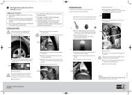
Federbeinausbau vorne<br />
!<br />
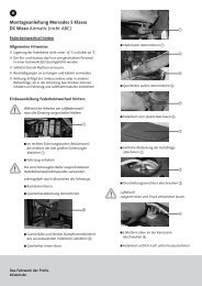
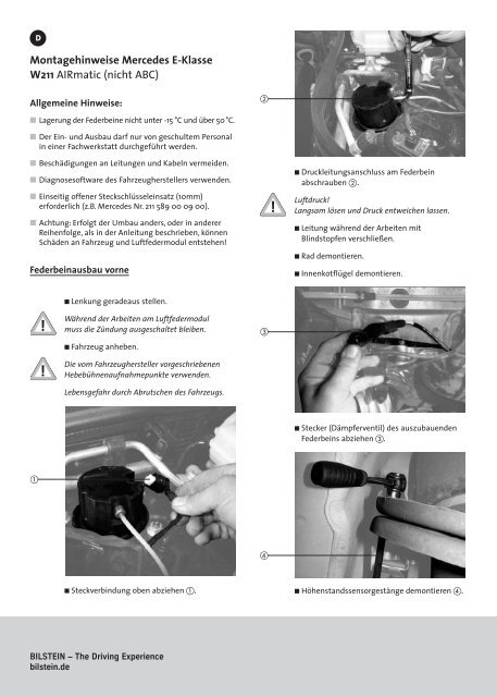
■ Druckleitungsanschluss am Federbein<br />
abschrauben .<br />
Luftdruck!<br />
Langsam lösen und Druck entweichen lassen.<br />
■ Leitung während der Arbeiten mit<br />
Blindstopfen verschließen.<br />
■ Rad demontieren.<br />
■ Innenkotflügel demontieren.<br />
■ Lenkung geradeaus stellen.<br />
!<br />
!<br />
Während der Arbeiten am Luftfedermodul<br />
muss die Zündung ausgeschaltet bleiben.<br />
■ Fahrzeug anheben.<br />
Die vom Fahrzeughersteller vorgeschriebenen<br />
Hebebühnenaufnahmepunkte verwenden.<br />
Lebensgefahr durch Abrutschen des Fahrzeugs.<br />
<br />
■ Stecker (Dämpferventil) des auszubauenden<br />
Federbeins abziehen .<br />
<br />
<br />
■ Steckverbindung oben abziehen .<br />
■ Höhenstandssensorgestänge demontieren .<br />
BILSTEIN – The Driving Experience<br />
bilstein.de
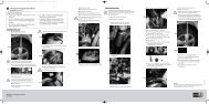
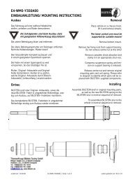
■ Traggelenk oberer Querlenker lösen und mit<br />
geeignetem Werkzeug abdrücken .<br />
■ Stabilisator demontieren.<br />
■ 3 Muttern am Federbeindom lösen .<br />
■ Unteren Querlenker herunterdrücken und<br />
Federbein seitlich nach unten herausnehmen.<br />
<br />
Federbeineinbau vorne<br />
■ Luftfederbeine vor dem Einbau überprüfen:<br />
Stoßdämpferrohr darf kein seitliches Spiel haben und<br />
unter der Faltmanschette muss der pralle Luftbalg zu<br />
ertasten sein. Andernfalls sind die Fe derbeine defekt<br />
und dürfen nicht verbaut werden.<br />
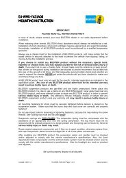
■ Innere Befestigung des unteren Querlenkers<br />
lösen .<br />
■ Selbstsichernde Muttern erneuern.<br />
■ Alle beweglichen, fahrwerksrelevanten Schraub -<br />
verbindungen erst im fahrfertigen Zustand vollständig<br />
festziehen, dabei Vorgaben und Anzugs momente des<br />
Fahrzeugherstellers befolgen.<br />
<br />
<br />
■ Untere Befestigungsgabel des Federbeins<br />
demontieren .<br />
■ Neues Federbein nach oben einsetzen und die<br />
oberen Muttern anlegen .
■ Innenkotflügel montieren.<br />
■ Rad montieren.<br />
<br />
<br />
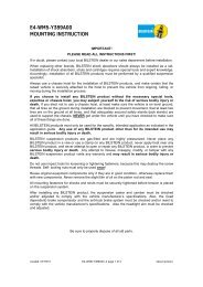
■ Federbeingabel am unteren Querlenker montieren<br />
.<br />
■ Stabilisator montieren.<br />
■ Traggelenk oberer Querlenker montieren.<br />
!<br />
!<br />
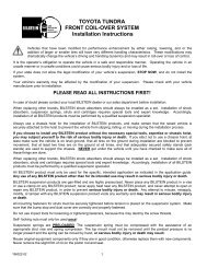
■ Druckleitung anschrauben (2Nm) .<br />
O-Ring überprüfen – falls nötig, erneuern.<br />
■ Steckverbindung oben einstecken.<br />
Fahrzeug niemals mit druckloser Luftfederung<br />
vollständig von der Hebebühne ablassen.<br />
■ Fahrzeug bis zur serienmäßigen Fahrzeughöhe<br />
von der Hebebühne ablassen.<br />
<br />
■ Motor starten, min. 2 Minuten warten, An -<br />
hebefunktion der Bordelektronik betätigen .<br />
■ Höhenstandssensorgestänge montieren .<br />
<br />
<br />
■ Hebebühne zunächst langsam, erst wenn sich<br />
das Fahrzeug selbstständig anhebt, vollständig<br />
ablassen.<br />
■ Stecker (Dämpferventil) des einzubauenden<br />
Federbeins einstecken .<br />
■ <strong>AIRmatic</strong> auf Dichtheit prüfen.<br />
■ Beim Umbau gelöste Schrauben im fahrfertigen<br />
Zustand nach Vorgaben des Herstellers<br />
vollständig festziehen.<br />
E4-WM5-Y348A00
GB<br />
Fitting Information <strong>Mercedes</strong> E-Class<br />
<strong>W211</strong> <strong>AIRmatic</strong> (not ABC)<br />
General information:<br />
<br />
■ Struts not to be stored below -15 °C and above 50°C.<br />
■ Fitting and dismantling is only to be performed by fully<br />
qualified personnel at a specialist garage.<br />
■ Avoid damage to air lines and cables.<br />
■ Use car manufacturer’s diagnostic software.<br />
■ Socket wrench insert open on one side (10 mm) required<br />
(e.g. <strong>Mercedes</strong> No. 211 589 00 09 00).<br />
■ Caution! Damage to the vehicle and the air suspension<br />
module can be incurred if work is carried out in a<br />
manner other than that specified in the instructions or<br />
in a different sequence.<br />
!<br />
■ Screw off pressure line union on strut .<br />
Air pressure!<br />
Loosen slowly and allow air to escape.<br />
■ Seal off line with plugs.<br />
■ Dismantle wheel.<br />
■ Dismantle the inner fender.<br />
Dismantling the front struts<br />
!<br />
!<br />
■ Set steering to straight ahead.<br />
The ignition must remain switched off during<br />
the work on the air spring module.<br />
■ Raise vehicle.<br />
Use the lifting platform (hoist) holding points<br />
prescribed by the vehicle manufacturer.<br />
Vehicle slippage can cause danger to life and limb.<br />
<br />
■ Remove plug (shock absorber valve) of the<br />
strut being dismantled .<br />
<br />
<br />
■ Remove top plug connection .<br />
■ Dismantle level sensor linkage .<br />
Engineered for performance.<br />
bilstein.de
■ Loosen the support link of the upper track<br />
control arm and press off using suitable tools .<br />
■ Dismantle stabilizer.<br />
■ Loosen the 3 nuts on the strut dome .<br />
■ Push the bottom track control arm down and<br />
remove the strut sideways and downwards.<br />
<br />
Fitting the front struts<br />
■ Check struts prior to fitting: the shock absorber tube<br />
should have no side play and it must be possible to feel<br />
the fully inflated air-bellow beneath the dust cover.<br />
Otherwise, the struts are defective and must not be<br />
fitted.<br />
■ Loosen the inner fixture of the bottom track<br />
control arm .<br />
■ Renew self-locking nuts.<br />
■ Only fully tighten all movable, suspension related screw<br />
connections in ready-to-drive condition observing the<br />
manufacturer’s specifications and tightening torques.<br />
<br />
<br />
■ Remove the strut bottom fixing fork .<br />
■ Fit new strut upwards and position the upper<br />
nuts .
■ Assemble inner fender.<br />
■ Mount the wheel.<br />
<br />
<br />
■ Assemble strut fork on the bottom track control<br />
arm .<br />
■ Assemble stabilizer.<br />
■ Assemble support link of the upper track<br />
control arm.<br />
!<br />
!<br />
■ Screw on pressure line (2Nm) .<br />
Check “O” ring – renew if necessary.<br />
■ Insert top plug.<br />
Never under any circumstances allow the vehicle<br />
to be fully lowered from the lifting platform<br />
(hoist) with the air suspension depressurized.<br />
■ Lower vehicle up to standard vehicle height<br />
from the lifting platform.<br />
<br />
■ Start engine, wait 2 minutes, operate the<br />
raising function of the electronics .<br />
■ Assemble level sensor linkage .<br />
<br />
<br />
■ Initially lower the lifting platform slowly and<br />
only lower completely when the vehicle raises<br />
of its own accord.<br />
■ Insert plug (shock absorber valve) of the strut<br />
being fitted .<br />
■ Check <strong>AIRmatic</strong> for leaks.<br />
■ Fully tighten screws loosed during the work in<br />
ready-to-drive condition in accordance with<br />
the manufacturer’s specifications.<br />
E4-WM5-Y348A00