Losi XXX-CR Manual - Robitronic
Losi XXX-CR Manual - Robitronic
Losi XXX-CR Manual - Robitronic

Create successful ePaper yourself
Turn your PDF publications into a flip-book with our unique Google optimized e-Paper software.
SUPER DIALED SETUP!<br />
KIT SETUP<br />
0°<br />
24mm, Arms level<br />
-1°<br />
30°<br />
No<br />
27.5wt.<br />
#56<br />
Orange<br />
None<br />
Bottom<br />
Narrow<br />
Rack<br />
None<br />
3-B, 1-Ball Stud Washer<br />
3-Middle<br />
Short<br />
Yes, on Tower<br />
3° Pivot, 0° Hubs<br />
2°<br />
23mm, Dogbones just under level<br />
-1°<br />
Center<br />
Steel Dogbones, Steel w/Shims<br />
None<br />
27.5wt.<br />
#56<br />
Pink<br />
.170” (1-“A” Spacer (.120”), 1-1/32” (.030”) Spacer<br />
2-B, 3 Ball Stud Washers<br />
1-Inside<br />
Short<br />
Standard/Middle<br />
<strong>XXX</strong>-<strong>CR</strong><br />
Forward<br />
X-Wide Body Red Standard 78T<br />
Big Shot Red Standard<br />
Trim inside corners of Foam inserts.<br />
26
STEP I-01<br />
Intro to the <strong>XXX</strong>-<strong>CR</strong> <strong>Manual</strong><br />
INTRO<br />
Welcome Team <strong>Losi</strong> <strong>XXX</strong>-<strong>CR</strong> Owner!<br />
Thank you for selecting the <strong>XXX</strong>-<strong>CR</strong> as your new racing buggy. The <strong>XXX</strong>-<strong>CR</strong> has already distinguished itself as a top caliber racing chassis<br />
and as you will see, we have made every effort to produce a kit that is not only the most competitive but also easy to build and maintain.<br />
The simple bag-by-bag assembly sequence and easily followed instructions and drawings combined with Team <strong>Losi</strong>’s world famous quality<br />
fitting parts will make building the <strong>XXX</strong>-<strong>CR</strong> a most enjoyable project.<br />
Before you open the first bag, or start assembly, please take a moment to read through the following instructions. This will familiarize<br />
you with the various parts, assembly tips, and descriptions as well as the tools needed. Taking an extra moment before starting can save a<br />
good deal of time and assure proper assembly.<br />
Good luck and good racing,<br />
Team <strong>Losi</strong><br />
<strong>XXX</strong>-<strong>CR</strong> COMPLETED KIT SPECIFICATIONS<br />
Overall Chassis Length: 14-3/4in (378mm) Wheelbase: 10-1/2in (259mm) *Front Track Width: 9-7/8in (251mm)<br />
Overall Length w/Tires: 15in (381mm) *Overall Height: 5-1/4in (133mm) *Rear Track Width: 9-3/4in (248mm)<br />
Note: Final kit weight will vary depending on accessories used.<br />
*All measurements taken at ride height (23mm).<br />
Table 1: <strong>XXX</strong>-<strong>CR</strong> Completed Kit Specifi cations.<br />
Kit/<strong>Manual</strong> Organization:<br />
The kit is composed of different bags marked A through F. Each<br />
bag contains all of the parts necessary to complete a particular section<br />
of the kit. Some of these bags have sub-assembly bags within<br />
them. It is essential that you open only one bag at a time and follow<br />
the correct assembly sequence, otherwise you may face difficulties in<br />
finding the correct part. It is helpful to read through the instructions<br />
for an entire bag prior to beginning assembly. Next to each of the step<br />
numbers is a check box. At the completion of each step, place a check<br />
in this box so that if you must stop and come back to the assembly,<br />
you will be able to pick up where you left off.<br />
For your convenience, an actual-size Hardware Identification<br />
Guide is included as a fold-out page at the back of this manual. Hardware<br />
that is not easily differentiable in each step is called out with<br />
an icon which contains a small<br />
picture of the part genre (referenced<br />
on the Hardware Identification<br />
Guide), the quantity of<br />
that part required for what is<br />
shown in the step, and the size<br />
or name of that part. To check a part, hold it against the silhouette until<br />
the correct part is identified. Associated with each of these parts, in<br />
the Hardware Identification Guide, is a LOSA-Number which is used<br />
when ordering replacement parts for your <strong>XXX</strong>-<strong>CR</strong>. In some cases,<br />
extra hardware has been supplied for parts that may be easy to lose.<br />
Components used in each step are identified by their relative<br />
LOSA-Number and the component’s name. With the exception of<br />
a few parts, these are not referenced in the Hardware Identification<br />
Guide.<br />
The molded parts in Team <strong>Losi</strong> kits are manufactured to demanding<br />
tolerances. When screws are tightened to the point of being<br />
snug, the parts are held firmly in place. For this reason, it is very<br />
important that screws not be overtightened in any of the plastic<br />
parts.<br />
In some steps there will be a filled black circle with a white<br />
number. These indicate the specific order by which assembly must<br />
occur. In cases where steps are repeated (front/rear or left/right) these<br />
numbers may be omitted. Please note that these numbers will not call<br />
out every sub-step required for the step’s assembly procedures, they<br />
will only highlight the critical order required for assembly.<br />
In each step, there are specific “Detail Icons” (shaped like a stop<br />
sign) that call out critical precautions or assembly tips for the process.<br />
There is a reference key that describes the meaning of each of<br />
the icons located on the fold-out Hardware Identification Guide at<br />
the back of this manual.<br />
To ensure that parts are not lost during construction, it is recommended<br />
that you work over a towel or mat to prevent parts from<br />
rolling away.<br />
IMPORTANT SAFETY NOTES:<br />
1. Select an area for assembly that is away from the reach of small<br />
children. Some parts in this kit are small and can be swallowed<br />
by children, causing choking and possible internal injury;<br />
PLEASE USE CAUTION!<br />
2. The shock fluid and greases supplied should be kept out of children’s<br />
reach. They are not intended for human consumption!<br />
3. Exercise care when using any hand tools, sharp instruments, or<br />
power tools during construction.<br />
4. Carefully read all manufacturer’s warnings and cautions for any<br />
chemicals, glues, or paints that may be used for assembly and<br />
operating purposes.<br />
i
L<br />
HARDWARE<br />
Cap Head Flat Head Button Head Set<br />
4-40 x 3/8” (A6206)<br />
4-40 x 3/8” (A6210)<br />
4-40 x 1/4” (A6234)<br />
4-40 x 3/32” (A6248)<br />
4-40 x 1/2” (A6204)<br />
4-40 x 5/8” (A6233)<br />
4-40 x 3/8” (A6229)<br />
4-40 x 5/8” (A6248)<br />
4-40 x 3/4” (A6205)<br />
4-40 x 7/8” (A6226)<br />
4-40 x 1/2” (A6256)<br />
4-40 x 7/8” (A6216)<br />
4-40 x 1” (A1133)<br />
4-40 x 1-1/8” (A3034)<br />
4-40 x 1-1/2” (A3034)<br />
3mm x 6mm (A6238)<br />
Ball Studs Washers Metal Spacers Plastic Spacers<br />
.215” Standard Neck HD (A6025)<br />
Ball Stud (A6215)<br />
3/16” x .100” (A3016)<br />
3/32” x .050” (A1122)<br />
1/4” Standard Neck HD (A6026)<br />
1/8” x .020” Stainless (A6350)<br />
3/16” x .240” (A9941)<br />
1/8” x 1/32” (.0325”) (A2127)<br />
3/8” Standard Neck HD (A6027)<br />
1/8” x 1/16” (.0625”) (A5050)<br />
.345 Short Neck HD (A6029)<br />
1/8” x .030” Gold (A6350)<br />
1/2” x .010” (A6230)<br />
1/8” x .140” (“A”) (A5015)<br />
3/16” x .140” (A3033)<br />
Ball Bearings Roll/Solid Pins Retaining Clips Nuts (Lock/Plain)<br />
3/32” x 3/16” (A6912)<br />
5mm x 8mm (A6907)<br />
1/8” x 3/8” (A6909)<br />
1/16” x 7/16” Roll (A6401)<br />
2.5mm x 12mm Solid (A6407)<br />
3/32” x .930” Solid (A6081)<br />
3/32” E-Clip (A6103)<br />
1/8” E-Clip (A6100)<br />
L 4-40 x 3/16” (Mini) (A6306)<br />
4-40 x 1/4” (6300)<br />
3/16” x 3/8” (A6916)<br />
3/32” x 1.050” Solid (A6082)<br />
1/8” x 1.246” Solid (A6088)<br />
Body Clip (A8200)<br />
L 4-40 x 1/4” (A6308)<br />
1/8” x 1.420” Solid (A6089)<br />
L 6-40 x 5/16” (A1610)<br />
1/2” x 3/4” (A6908)<br />
1/8” x 1.900” Solid (A6092)<br />
L 10-32 x 3/8” (A6303)<br />
DETAIL ICON REFERENCE KEY<br />
1 These numbers are used to identify the critical order in which assembly must occur. *Note: They will not call out every stage of the assembly process.<br />
LOCTITE Apply Loctite® CLEAR<br />
GREASE<br />
Apply Clear<br />
Grease<br />
GLUE<br />
Apply CA Glue<br />
GREASE<br />
Apply Synthetic<br />
White Grease<br />
OIL<br />
Fill With<br />
Silicone Oil<br />
Pre-Tap<br />
Pay Special<br />
Attention CUT Cut/Trim<br />
Ensure Free<br />
Movement<br />
Ensure Free<br />
Rotation<br />
Ensure Proper<br />
Orientation<br />
Push Firm<br />
L<br />
Side Shown<br />
x2<br />
L<br />
R<br />
R<br />
Assemble Other<br />
Side the Same<br />
Repeat/Build<br />
Multiple<br />
Screw Partially<br />
DO NOT<br />
Over Tighten/<br />
Snug Tight<br />
Tighten<br />
25
INTRO<br />
TOOLS REQUIRED FOR ASSEMBLY<br />
Team <strong>Losi</strong> has supplied all necessary Allen wrenches and a special wrench that is needed for assembly and adjustments. The following common<br />
tools will also be required: Needle-nose pliers, regular pliers, hobby knife, scissors or other body cutting/trimming tools, and a soldering<br />
iron may be necessary for radio installation. 3/16”, 1/4”, 5/16”, and 11/32” nut drivers are optional.<br />
RADIO/ELECTRONICS<br />
A suggested radio layout is provided in this manual. Your high performance R/C center should be consulted regarding specific questions<br />
pertaining to radio/electrical equipment.<br />
HARDWARE IDENTIFICATION<br />
When in question, use the Hardware Identification Guide at the back of this manual.<br />
• For screws, the prefix number designates the thread size and number of threads per inch (i.e., 4-40 is a #4 size thread with 40 threads per<br />
inch). The second number, or fraction, designates the length of the screw. For cap head and button head screws, this number refers to the<br />
length of the threaded portion of the screw. For flat head and set screws, this number refers to the overall length of the screw.<br />
• Bearings and bushings are referenced by the inside diameter (I.D.) x outside diameter (O.D.).<br />
• Shafts and pins are designated by type (Roll, Solid) and referenced by diameter x length.<br />
• Washers, Spacers and Shims are described by inside diameter or the screw size that will pass through the inside diameter x the thickness<br />
or by their designated application (i.e., Ball Stud washer is primarily used under a Ball Stud).<br />
• Retaining Clips are sized by the shaft diameter that they attach to or by type (Body). The Hardware Icon associated with E/C-Clips only<br />
designates the part genre of clips, not the actual part.<br />
• Nuts come in four types, Non-Flanged, Flanged (F), Plain, and Locking (L) (designated on the Hardware Icons). The prefix number designates<br />
the thread size and number of threads per inch. The second number, or fraction, designates the size of the hex. For example, L 4-40<br />
x 1/4” designates a Lock nut that will thread onto a 4-40 screw using a 1/4” nut driver.<br />
• Ball studs are described by the length of the neck between the base and the bottom of the ball (i.e., standard, short) and the length of the<br />
threaded portion.<br />
TABLE OF CONTENTS<br />
SECTIONS<br />
1. INTRODUCTION................................................... i<br />
Kit/<strong>Manual</strong> Organization ................................... i<br />
Important Safety Notes ...................................... i<br />
Tools Required for Assembly ............................ ii<br />
Radio/Electronics .............................................. ii<br />
Hardware Identification .................................... ii<br />
2. Bag A: Front Clip ................................................ 1-3<br />
3. Bag B: Chassis ..................................................... 4-5<br />
4. Bag C: Rear Clip ................................................. 6-8<br />
5. Bag D: Transmission ......................................... 9-11<br />
6. Bag E: Shocks ................................................. 12-13<br />
7. Bag F: Final Chassis/Electronics ..................... 14-18<br />
8. Checklist Before Your First Run ........................19<br />
9. Setup Guide .................................................... 20-23<br />
10. Blank <strong>XXX</strong>-<strong>CR</strong> Setup Sheet.................................24<br />
11. Hardware Identification Guide ...........................25<br />
12. Filled-out <strong>XXX</strong>-<strong>CR</strong> Kit Setup Sheet....................26<br />
TABLES<br />
Table 1: <strong>XXX</strong>-<strong>CR</strong> Completed Kit Specifications ........ i<br />
Table 2: Servo Installation ...........................................4<br />
Table 3: Motor Gearing ..............................................20<br />
Team <strong>Losi</strong> is continually changing and improving designs; therefore, the actual part may appear slightly different than the illustrated part. Illustrations of parts and assemblies<br />
may be slightly distorted to enhance pertinent details.<br />
ii
STEP A-01<br />
Steering Assembly<br />
BAG A<br />
<br />
STEP A-02<br />
Kickplate Assembly<br />
Tighten the 6-40 x 5/16” Nut all the way<br />
down and then loosen it 2 full turns.<br />
x2<br />
4-40 x 3/8”<br />
SOLID x1<br />
3/32” x .930”<br />
1/8” x .030”<br />
x2<br />
4-40 x 1/2”<br />
A1620<br />
Spring Cap<br />
A1621<br />
Idler Arm<br />
A1610<br />
Servo Saver Spring<br />
x2 Std. .215”<br />
x1<br />
L 6-40 x 5/16”<br />
x1<br />
A4122<br />
Steering Brace<br />
x4<br />
3/32” x 3/16”<br />
A1233<br />
Steering Bushing<br />
A1620<br />
Servo Saver Top<br />
Std. 1/4”<br />
x2<br />
A1621<br />
Steering Rack<br />
x3<br />
L 4-40 x 3/16”<br />
A1621<br />
Servo Saver Bottom<br />
A1610<br />
Steering Post<br />
A4122<br />
Kickplate<br />
<br />
STEP A-03<br />
Front Suspension Assembly<br />
A4129<br />
Front Pivot<br />
A1122<br />
Spindle Carrier,<br />
Left<br />
SOLID<br />
x1<br />
3/32” x 1.050”<br />
x4<br />
3/32” E-Clip<br />
x2<br />
1/8” E-Clip<br />
x1<br />
3/32” x .050”<br />
x2<br />
L 4-40 x 3/16”<br />
SOLID<br />
x1<br />
1/8” x 1.420”<br />
A9956<br />
Hinge Pin Brace<br />
A1112<br />
Front Arm<br />
A1122<br />
Spindle, Left<br />
x2<br />
3/16” x 3/8”<br />
SOLID<br />
x1<br />
3/32” x .930”<br />
x1<br />
3/16” x .100”<br />
x2<br />
Std. 1/4”<br />
A1133<br />
Front Axle<br />
L<br />
1
STEP A-04<br />
Front Bulkhead Assembly<br />
BAG A<br />
x2<br />
4-40 x 1/4”<br />
x4<br />
4-40 x 3/8”<br />
A1104<br />
Shock Tower,<br />
Front<br />
x2<br />
4-40 x 3/4”<br />
Std. 3/8”<br />
x2<br />
Ball Stud<br />
x2<br />
A4122<br />
Bulkhead, Front<br />
<br />
STEP A-05<br />
Front Clip Assembly<br />
x1<br />
4-40 x 3/8”<br />
A4118<br />
Front Bumper<br />
x2<br />
4-40 x 5/8”<br />
x2<br />
4-40 x 7/8”<br />
2
STEP A-06<br />
BAG A<br />
Tierod Assembly and Installation<br />
•<br />
•<br />
Use the Team <strong>Losi</strong> flat wrench to hold the Turnbuckle while installing the Ball Cups.<br />
Be sure to install the assembled Tierod onto the car with the groove (next to the center square section) on the driver’s left side for easier<br />
adjustment later.<br />
Front Camber Tierod<br />
(71.6mm)<br />
(2.819in)<br />
x2<br />
A6003<br />
Foam Thing<br />
(73.0mm)<br />
(2.874in)<br />
Steering Tierod<br />
A6016<br />
Ball Cup<br />
L<br />
<br />
STEP A-07<br />
Completed Front Clip Assembly<br />
3
STEP B-01<br />
Servo Assembly<br />
BAG B<br />
JR<br />
Airtronics<br />
Servo Manufacturer, Make/Model<br />
Mount<br />
Position<br />
Servo<br />
Horn<br />
All (DZ9000T/S DOES NOT FIT) 1 23T<br />
94357Z, 94358Z, 94649Z, 94360Z,<br />
94452Z, 94758Z, 94737Z, 94738Z<br />
94102Z, 94112Z 1<br />
3<br />
23T<br />
3 4<br />
1 2<br />
4 3<br />
2 1<br />
Hitec<br />
All 1 24T<br />
Futaba<br />
KO<br />
All (S9102 DOES NOT FIT) 2 25T<br />
2<br />
PDS-2123, 2344, 2363, 2365, 2366<br />
1<br />
Table 2: Servo assembly and installation.<br />
• Ensure the servo gear is centered before attaching<br />
the Servo Horn. This is best accomplished<br />
by connecting the servo to the radio<br />
system and setting the trim to center.<br />
• Install the Servo Mounts in the orientation<br />
corresponding to the numbered diagram to<br />
the above right and Table 2.<br />
• DO NOT tighten the four 4-40 x 3/8” Cap<br />
Head Screws all the way, they must be tightened<br />
after assembly to the Chassis is complete<br />
to ensure proper alignment.<br />
23T<br />
Servo Screw<br />
(Not Supplied)<br />
x1<br />
L 4-40 x 3/16”<br />
Ball Stud<br />
x1<br />
x4<br />
1/8” x .030”<br />
x1<br />
Std. .215”<br />
A1620<br />
Servo Horn<br />
(See Table 2)<br />
A1620<br />
Servo Mount<br />
x4<br />
4-40 x 3/8”<br />
Servo<br />
(Not Supplied)<br />
<br />
STEP B-02<br />
Servo Installation<br />
• First place the Servo into the Chassis<br />
and place the Chassis Stiffener on top to<br />
ensure the servo is centered in-between<br />
the Mounts and as low as possible. Remove<br />
and tighten the four 4-40 x 3/8”<br />
Cap Head Screws and continue with the<br />
installation.<br />
A4105<br />
Chassis Stiffener<br />
x4<br />
4-40 x 3/8”<br />
A4105<br />
Chassis<br />
4
STEP B-03<br />
Chassis Assembly<br />
BAG B<br />
Steering Link<br />
x2<br />
4-40 x 3/8”<br />
A4123<br />
Body Mount<br />
(1.374in)<br />
(34.9mm)<br />
A6010<br />
Ball Cup, Short<br />
A6265<br />
Threaded Insert<br />
• The Steering Link length will vary depending<br />
on the brand and model of Servo<br />
used. This length is only a starting point<br />
and will most likely need to be adjusted<br />
in Step F-01.<br />
<br />
STEP B-04<br />
Completed Chassis<br />
5
STEP C-01<br />
Dogbone Assembly<br />
BAG C<br />
A3081<br />
Dogbone<br />
A3083<br />
Universal Yoke<br />
x1<br />
4-40 x 3/8”<br />
5<br />
3<br />
4<br />
1<br />
A3027<br />
Bearing Cross<br />
• Install the Yoke onto the Cross Ball pins<br />
by first inserting one pin of the Ball into<br />
one “ear” of the Yoke at a slight angle.<br />
Gently spread the “ears” of the Yoke and<br />
slip the second “ear” of the Yoke over<br />
the remaining pin on the ball.<br />
x1<br />
4-40 x 3/32”<br />
2<br />
SOLID x1<br />
2.5mm x 12mm<br />
A3015<br />
Rear Axle<br />
x2<br />
<br />
STEP C-02<br />
Rear Hub Carrier Assembly<br />
1<br />
Std. 3/8”<br />
x1<br />
Ball Stud<br />
x3<br />
2<br />
3<br />
x2<br />
3/16” x 3/8”<br />
4<br />
ROLL<br />
x1<br />
1/16” x 7/16”<br />
A2129<br />
Rear Hub Carrier<br />
x1<br />
3/16” x .240”<br />
A9941<br />
Axle Spacer<br />
L<br />
6
STEP C-03<br />
Rear Suspension Assembly<br />
BAG C<br />
A2113<br />
Rear Pivot<br />
x1<br />
1/8” x .020”<br />
CAUTION! The Rear Arms are<br />
marked with dots to designate the<br />
orientation. Note that 1 dot is for the<br />
left and 2 dots is for the right side.<br />
x2<br />
1/8” x 1/16”<br />
A4139<br />
Forward, Rear<br />
Pin Brace<br />
SOLID<br />
A2132<br />
Rear Arm<br />
x1<br />
1/8” x 1.900”<br />
x4<br />
1/8” E-Clip<br />
SOLID x1<br />
1/8” x 1.246”<br />
<br />
STEP C-04<br />
Rear Bulkhead Assembly<br />
<br />
STEP C-05<br />
Rear Plate Assembly<br />
x4<br />
4-40 x 1/2”<br />
x2<br />
4-40 x 1/4”<br />
A2100<br />
Rear Bulkhead/<br />
Shock Tower<br />
x2<br />
4-40 x 7/8”<br />
x2<br />
Short .345”<br />
A4221<br />
Wing Mount<br />
A2106<br />
Pivot Plate<br />
x5<br />
4-40 x 3/8”<br />
7
STEP C-06<br />
BAG C<br />
Tierod Assembly and Installation<br />
•<br />
•<br />
Use the Team <strong>Losi</strong> flat wrench to hold the Turnbuckle while installing the Ball Cups.<br />
Be sure to install the assembled Tierod onto the car with the groove (next to the center square section)<br />
on the driver’s left side for easier adjustment later.<br />
Rear Camber Tierod<br />
x2<br />
(3.074in)<br />
(78.1mm)<br />
A6003<br />
Foam Thing<br />
A6016<br />
Ball Cup<br />
L<br />
<br />
STEP C-07<br />
Completed Rear Suspension<br />
8
STEP D-01<br />
Differential Assembly<br />
BAG D<br />
• Apply a small amount of Clear Diff Grease to<br />
both Diff Outdrives and the Diff Ring Shims<br />
before installing the Diff Rings.<br />
• Apply enough Clear Diff Grease to the top side<br />
of the Diff Rings, or to both sides of recessed<br />
Ball section in the Diff Gear (after Diff Balls<br />
are installed) to cover the Diff Balls when the<br />
Diff is assembled.<br />
• Assemble the Diff and tighten until some resistance<br />
is felt, see the Final Checklist and Setup<br />
Guide for final Diff adjustment procedures.<br />
x2<br />
5mm x 8mm<br />
4<br />
A3038<br />
Outdrive, Female<br />
Large Center Hole<br />
A3018<br />
Thrust Bearing<br />
5<br />
2<br />
A6951<br />
Diff Balls, Carbide<br />
A3036<br />
Diff Gear, 51T<br />
A3039<br />
Diff Ring<br />
(Chrome)<br />
A3039<br />
Diff Ring Shim<br />
(Bronze)<br />
A3038<br />
Outdrive, Male<br />
Small Center Hole<br />
A3078<br />
Foam Diff Seal<br />
A2908<br />
Diff Spring<br />
• The Diff Ring Shims are optional. If you choose<br />
not to use them (See Setup Guide), you must<br />
install the smaller Diff Shims on the outside of<br />
the Diff before installing the Diff into the Gearbox<br />
case.<br />
A3078<br />
Diff Screw<br />
3<br />
1<br />
A2911<br />
Diff Nut<br />
<br />
STEP D-02<br />
Transmission Assembly<br />
A3041<br />
Motor Plate<br />
A3033<br />
Gearbox, Right<br />
A2937<br />
Idler Shaft<br />
x1<br />
3/16” x .140”<br />
A3079<br />
Idler Gear<br />
A9930<br />
Top Shaft<br />
x2<br />
3/16” x 3/8”<br />
A3033<br />
Gearbox, Left<br />
x1<br />
4-40 x 3/8”<br />
x2<br />
1/8” x 3/8”<br />
• The Diff Ring Shims are optional. If you choose<br />
not to use them (See Setup Guide), you must<br />
install the smaller Diff Shims on the outside of<br />
the Diff before installing the Diff into the Gearbox<br />
case.<br />
x2<br />
1/2” x 3/4”<br />
A3034<br />
2-56 x 5/8"<br />
Cap Head Screw<br />
x2<br />
4-40 x 1-1/8”<br />
9
STEP D-03<br />
Slipper Clutch Installation<br />
BAG D<br />
x2<br />
4-40 x 1/4”<br />
A3132<br />
Slipper Plate<br />
A4123<br />
Motor Guard<br />
A3123<br />
Slipper Pad<br />
A3981<br />
Spur Gear, 78T<br />
A3124<br />
Spring Spacer<br />
A3125<br />
Slipper Spring<br />
A3135<br />
Spring Retaining<br />
Washer<br />
x1<br />
L 4-40 x 1/4”<br />
<br />
STEP D-04<br />
Motor Installation<br />
Motor<br />
(Not Supplied)<br />
• When setting the gear mesh, leave a small amount of backlash<br />
for proper function. Too much backlash will cause failure,<br />
so be sure to check the mesh at different points in the<br />
rotation of the Spur Gear.<br />
A3042<br />
Gear Cover<br />
Pinion Gear<br />
(Not Supplied)<br />
x2<br />
1/8” x .030”<br />
x2<br />
3mm x 6mm<br />
A3043<br />
Gear Cover Plug<br />
x3<br />
4-40 x 3/8”<br />
10
STEP D-05<br />
Transmission Installation<br />
BAG D<br />
x1<br />
4-40 x 1-1/2”<br />
Ball Stud<br />
x1<br />
x2<br />
4-40 x 3/8”<br />
CAUTION! Ensure the Dogbone is<br />
inserted into the slot in the Outdrive<br />
before installing the Transmission.<br />
<br />
STEP D-06<br />
Completed Rear Clip Assembly<br />
11
STEP E-01<br />
Shock Assembly<br />
BAG E<br />
•<br />
•<br />
•<br />
•<br />
•<br />
•<br />
•<br />
Match short front Shock Bodies with assembled short front Shock Shafts and long rear Shock Bodies to assembled long rear Shock<br />
Shafts.<br />
Holding the shock body inverted, fill the Shock Body with Shock Oil up to the bottom of the threads inside the Shock Body.<br />
Insert shaft assembly with cartridge against the shock piston.<br />
Slowly tighten the Cartridge until it bottoms against the Shock Body. Do not tighten all the way.<br />
Slowly push Shock Shaft assembly into the Shock Body. This will bleed the excess oil out of the Shock.<br />
Once the Shaft is pushed all the way down into the Shock Body, tighten the Shock Cartridge the rest of the way with a 7/16” wrench or a<br />
pair of pliers approximately 1/8th of a turn.<br />
There should be no air in the Shocks as you move the Shaft in and out of the Shock Body. If there is; you will need to add some Oil and<br />
repeat the bleed process. If the Shock does not compress all the way, the shock has too much Oil. Simply loosen the Cartridge about 1/4<br />
turn and push the Shaft into the Body and retighten the Cartridge.<br />
A9940<br />
Ball Joint<br />
A5023<br />
Shock End<br />
A5054<br />
Shock Body,<br />
Front<br />
A5055<br />
Shock Body,<br />
Rear<br />
A5064<br />
Shock Shaft,<br />
Rear<br />
A5015<br />
Shock Cartridge<br />
A5060<br />
Shock Shaft,<br />
Front<br />
x1<br />
1/8” x 1/32”<br />
x1<br />
1/8” x 0.140”<br />
A5049<br />
Shock Adjustment<br />
Nut<br />
x4<br />
1/8” E-Clip<br />
A5046<br />
Shock Piston, #56<br />
(Red)<br />
A5129<br />
Spring, Front<br />
(Orange)<br />
A5150<br />
Spring, Rear<br />
(Pink)<br />
A5079<br />
Spring Cup<br />
12
BAG E<br />
<br />
STEP E-02<br />
Front Shock Installation<br />
<br />
STEP E-03<br />
Rear Shock Installation<br />
x2<br />
L 4-40 x 1/4”<br />
A5013<br />
Shock Bushing,<br />
Long<br />
A5013<br />
Shock Bushing,<br />
Short<br />
x2<br />
L 4-40 x 1/4”<br />
x1<br />
4-40 x 1/2”<br />
x1<br />
4-40 x 1/2”<br />
<br />
STEP E-04<br />
Completed Front and Rear Clips<br />
13
STEP F-01<br />
BAG F<br />
Front and Rear Clip Installation<br />
• The Servo Link installed in Step B-02 was set<br />
to an approximate length. The correct length<br />
will vary depending on the type of servo used,<br />
the radio settings, and the Servo Horn.<br />
• It may be necessary to adjust this length, after<br />
all radio gear is installed and the servo is centered<br />
properly, to obtain the maximum steering<br />
throw and have the Steering Bellcranks centered<br />
without having extreme trim settings on<br />
the radio.<br />
x6<br />
4-40 x 3/8”<br />
x2<br />
4-40 x 1/2”<br />
x4<br />
4-40 x 3/8”<br />
<br />
STEP F-02<br />
Speed Control Installation<br />
<br />
STEP F-03<br />
Receiver Installation<br />
Speed Control<br />
(Not Supplied)<br />
A4003<br />
Antenna Tip Cover<br />
Receiver<br />
(Not Supplied)<br />
A4002<br />
Antenna Tube<br />
A4004<br />
Double-Sided<br />
Tape<br />
A4004<br />
Double-Sided<br />
Tape<br />
14
STEP F-04<br />
Battery Installation<br />
BAG F<br />
A4114<br />
Battery Strap<br />
A4116<br />
Battery Pad<br />
1<br />
3<br />
This configuration is for<br />
use with a stick type battery<br />
back.<br />
2<br />
A4114<br />
Battery Spacer<br />
Foam<br />
x1<br />
Body Clip<br />
<br />
STEP F-05<br />
Tire Mounting<br />
• Using a pair of sharp scissors, carefully cut the<br />
inside corners of the Tire Foams away to allow<br />
for easier mounting on the Wheel as shown<br />
below.<br />
• Ensure there is no flashing on the bead of the<br />
Tires, if so, trim it away to allow for easier<br />
mounting on the Wheel.<br />
A7368R<br />
Rear Tire,<br />
Big Shot<br />
A7398<br />
Rear Tire Foam<br />
Foam Cross<br />
Section<br />
A7104<br />
Rear Wheel<br />
1<br />
A7204R<br />
Front Tire,<br />
Extra-Wide Body<br />
2<br />
A7297<br />
Front Tire Foam<br />
A7004<br />
Front Wheel<br />
15
STEP F-06<br />
Tire Gluing<br />
BAG F<br />
• The Tires need to be glued to the wheels. This can be done by using a fast-curing super glue or cyanoacrylate glue (LOSA7880, LOSA7881),<br />
available at your local hobby shop. Install a Tire gluing rubber band around the outside of the Tire, in line with the bead to hold it onto the<br />
Wheel.<br />
• Now slightly pull back the tire bead from the wheel and apply a thin bead of glue between the Tire bead and the Wheel all the way around,<br />
wait for this side to dry and do the same to the other side until the Tire is firmly adhered to the Wheel. Allow the glue to dry thoroughly<br />
before continuing.<br />
<br />
STEP F-07<br />
Tire Installation<br />
x2<br />
L 10-32 x 3/8”<br />
x2<br />
L 4-40 x 1/4”<br />
• When installing the mounted Tires, be sure to<br />
align the pin or hex feature in the Wheels with<br />
the pin or hex on the Axles before tightening<br />
the Nuts.<br />
16
STEP F-08<br />
Body and Wing Painting<br />
BAG F<br />
Painting:<br />
Prepare the Lexan® Body and Wings for painting by washing them thoroughly (inside and out) with warm water and liquid detergent.<br />
Dry both the Body and Wings with a clean, soft cloth. Use the supplied Window Masks to cover the windows from the inside. A high-quality<br />
masking tape should be used on the inside of the Body to mask off any stripes, panels, or designs that you wish to paint on the Body or Wings.<br />
Use acrylic lacquer or other paints recommended for Lexan® (polycarbonate). (NOTE: LEXAN® R/C CAR BODIES ARE MEANT TO<br />
BE PAINTED FROM THE INSIDE!) Apply paint to the inside of the Body and to the under-side of the Wings. Remove the masking tape<br />
for the next color and continue. Try to use darker colors first. If you use a dark color after a light color, apply a coat of white paint over the<br />
lighter color before applying the darker color, or if you are painting over white, coat it with silver. This will help prevent the darker color from<br />
bleeding through the lighter color.<br />
Mounting:<br />
After painting, trim the Body along the trim lines as shown below, emphasized by the dark shading in the figure below. There is an<br />
indented trim line around the Body which can be used as a guide for trimming. Make four 1/4”-diameter holes at the locations marked with<br />
dimples. There are two on the back of the Body and one on the right side of the Body. Also trim the oval shaped hole on the front of the Body.<br />
These will be the Body mounting and Antenna holes.<br />
Now trim the rear Wings along the trim lines shown below. Drill two 7/64” diameter holes in the dimples of both rear Wings. With the<br />
Wings painted and completely trimmed, mount the rear Wings to the Wing Mounts using two Body Clips. The shown Wing Washers (see<br />
Step F-09) are only necessary if the optional small rear Wing is not used.<br />
Stickers:<br />
After the Wings and Body are mounted, REMOVE THE PROTECTIVE FILM ON THE OUTER SURFACE, now you can apply<br />
the stickers. Cut the stickers from the sticker sheet that you wish to apply to the Body or Wing. Before removing the protective backing, find<br />
the desired location. Remove the backing completely and reattach an edge of the sticker to the shiny side of the backing material. Using the<br />
rest of the backing material as a handle, position the sticker and press firmly into place to complete its application.<br />
Front Wing<br />
17
STEP F-09<br />
Body and Wing Mounting<br />
BAG F<br />
A6016<br />
Wing Mount Washer<br />
x5<br />
Body Clip<br />
•<br />
•<br />
Optional Front Wing<br />
Install on top of Body and behind Shock Tower.<br />
Secure with the front Body Clip<br />
18
CHECKLIST<br />
BEFORE RUNNING YOUR NEW <strong>XXX</strong>-<strong>CR</strong> OFF-ROAD RACING BUGGY for the first time, you should run down the following<br />
checklist in order and complete the listed tasks. We’re sure you’re anxious to get out and run your new <strong>XXX</strong>-<strong>CR</strong> now that its built, but please<br />
note that fine tuning of the initial setup is an essential part of building a high performance racing buggy such as your new <strong>XXX</strong>-<strong>CR</strong>. Following<br />
this simple Checklist and the Team Tips will help to make the first run with your new car much more enjoyable.<br />
1. Breaking in the Differential:<br />
While holding the chassis with only the left side tires firmly on<br />
the ground, give the car about one quarter throttle, for 10 seconds.<br />
The right side tires should spin freely during this time. Repeat<br />
this with only the right side tires held firmly to the ground, allowing<br />
the left tires to spin. Feel the differential (diff) action and<br />
tighten slightly, if necessary. The differential should have a tight,<br />
thick feel when rotating it after final adjustment. CAUTION!<br />
YOUR DIFFERENTIAL SHOULD NEVER BE ALLOWED<br />
TO SLIP WHEN RUNNING (A SLIPPING DIFFERENTIAL<br />
<strong>CR</strong>EATES A “BARKING” SOUND). IF IT DOES, STOP IM-<br />
MEDIATELY AND TIGHTEN TO PREVENT DAMAGE.<br />
SEE “DIFFERENTIAL ADJUSTMENT” AND “SLIPPER<br />
ADJUSTMENT” IN THE SETUP GUIDE.<br />
2. Check for free suspension movement:<br />
All suspension arms and steering components should move freely.<br />
Any binds will cause the car to handle poorly.<br />
3. Set the ride height:<br />
Set the ride height on the rear so the dogbones are level (parallel)<br />
to the ground by adjusting the shock adjustment nuts, effectively<br />
increasing or decreasing pre-load on the springs. See the Setup<br />
Guide for additional information on ride height adjustment.<br />
4. Set the camber:<br />
Adjusting the camber tierod length changes the amount of camber.<br />
Using the Team <strong>Losi</strong> flat wrench to adjust the tierods once<br />
installed. Rotating the tierods towards the front end of the vehicle<br />
will shorten the length, increasing negative camber. Rotating<br />
the tierods towards the back of the car will lengthen them,<br />
increasing negative camber. Set the front tires to have 1 degree<br />
of negative camber and ensure that they are adjusted equally, left<br />
to right. Set the rear tires to have .5-1 degrees of negative camber<br />
and ensure that they are adjusted equally, left to right.<br />
5. Set the front toe-in:<br />
Adjust the front steering tierods so that when the servo is centered<br />
on the transmitter, the front tires are both pointing straight.<br />
Refer to the Setup Guide for more information on toe-in/out.<br />
6. Charge a battery pack:<br />
Charge a battery pack as per the battery manufacturer’s and/or<br />
charger manufacturer’s instructions so that radio adjustments<br />
can be made. Never plug the battery into the speed control backwards.<br />
7. Adjust the electronic speed control (ESC):<br />
Following the manufacturer’s instructions, adjust your speed<br />
control and set the throttle trim on your ESC so that the car does<br />
not creep forward when no transmitter input is applied. Make<br />
sure that there is not too much brake being applied when the<br />
trigger/stick is in the neutral position. Some speed controls have<br />
a high/low setting for the throttle and brake.<br />
8. Set the transmitter steering and throttle trim:<br />
The steering trim tab on the transmitter should be adjusted so<br />
that the car rolls straight when you are not touching the steering<br />
wheel/stick. If the servo and steering link were installed correctly,<br />
the wheels should turn equally to the left and right. If this<br />
is not the case, refer to Table 2 and ensure that the steering servo<br />
and horn were properly installed. Also check the Steering Link<br />
Length as noted in Step F-01. Make sure the throttle trim is set<br />
so that the motor does not run when in the neutral position. You<br />
may wish to run one “click” of brake to be safe.<br />
TIPS AND HINTS FROM THE TEAM<br />
Before you start making changes on your <strong>XXX</strong>-<strong>CR</strong> Off Road Racing Buggy, you need to make a few decisions. Tires, and how they are<br />
setup, have a tremendous impact on overall performance. Before you start making changes on the chassis setup, take a movement to observe<br />
a few of the fastest cars at the track and what type of tire and inner liner they are running. When making chassis changes, you should first<br />
decide where you feel the car needs to be different. This is commonly referred to as changing the “balance”. First decide if the front of the<br />
car needs to be adjusted or the back. You will want to work with the rear if the car enters the turn with the front end sticking, and tracking<br />
well, while the rear end either does not want to follow, or simply doesn’t know what it wants to do. The opposite is true if the rear end seems<br />
to want to push the front end through the corners or if the front drives into the corner uncontrollably. You will notice that several different<br />
adjustments have similar effects on the handling as well. You will find the best adjustment will become a personal decision based on the “feel”<br />
that each of these adjustments yield. This also reflects on the “balance” we referred to earlier. Never make more than one change at a time;<br />
if the change you made works adversely, or doesn’t address your need, return to the previous position and try something else. Team <strong>Losi</strong>’s<br />
development team has put hundreds of hours on the <strong>XXX</strong>-<strong>CR</strong> to arrive at the setup we put in the instruction manual. If you find that you have<br />
lost the “handle” go back to the kit (stock) setup, as this setup has proven to be reliable, consistent, and easy to drive.<br />
All of us at Team <strong>Losi</strong> are sure that you will find the <strong>XXX</strong>-<strong>CR</strong> Off Road Racing Buggy to be the most versatile and easiest car to drive<br />
fast, with great consistency. We hope the information in the following guide helps you to enjoy your <strong>XXX</strong>-<strong>CR</strong> Buggy, and racing it, as much<br />
as we do. For the latest in setup and accessory parts information, visit the Team <strong>Losi</strong> web site at: www.teamlosi.com regularly. For any technical<br />
questions go to the “Meet the Team” section of the site. We will try to answer your questions in the order received, to the best of our<br />
knowledge, by our own Team <strong>Losi</strong> R&D race team. Please check the Team <strong>Losi</strong> web site periodically to find out new setup information as<br />
we are always testing on all types of tracks and surfaces. Also note, that there are many ways to setup a car. The rules we follow can reverse<br />
sometimes with different driving styles or different setup styles, so test for yourself and you will find a setup that works right for you.<br />
19
SETUP GUIDE<br />
Tuning the Transmission of the <strong>XXX</strong>-<strong>CR</strong><br />
Differential Adjustment: Never allow the diff to slip; that’s what the slipper is for. Before trying to adjust your diff, you need to tighten the<br />
slipper until the spring is fully compressed. Next, hold the spur gear and right rear tire, then try turning the left rear tire forward. It should be<br />
very difficult to turn the left rear tire. If the tire turns easily, the diff is too loose. To tighten the diff, line up the slot in the diff screw with the<br />
groove in the left out drive. Place the 1/16” Allen wrench through both of these slots. This will lock the diff screw and the out drive together.<br />
While holding the Allen wrench in place, turn the right rear tire forward about 1/8 of a turn. Check the differential adjustment again and<br />
repeat the tightening process as necessary until the differential is no longer slipping. See “Slipper Adjustment” below, and then continue from<br />
here. The final differential adjustment check should be made by placing the car on carpet, grass, or asphalt and “punching” (quickly applying)<br />
the throttle. The differential should not slip. If it does, tighten the diff in 1/8-turn increments as described above until the slippage stops.<br />
Once the diff has been adjusted, it should still operate freely and feel smooth. If the diff screw starts to get tight before the diff is close to<br />
being adjusted properly (based on slip), the diff should be disassembled and inspected; you may have a problem with the differential assembly.<br />
Refer to the assembly instructions to ensure that the diff is properly assembled and that all parts are properly seated in the assembly.<br />
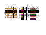
Motor Gearing: The important thing is to keep the motor in its optimal RPM range as much as possible around the entire track. This will<br />
depend on the straight-away length and the size of the infield turns. The chart below is a guide to give you a starting point. You may want<br />
to try gearing up (larger pinion or smaller spur) or down (smaller pinion or larger spur), one size at a time, noting the straight-away speed<br />
and acceleration through the infield.<br />
*NOTE: OVER GEARING (TOO LARGE OF A PINION OR TOO SMALL OF A SPUR) CAN CAUSE DAMAGE TO BOTH YOUR<br />
ELECTRONICS AND MOTOR. USE CAUTION WHEN SELECTING YOUR GEARING.<br />
Gear Ratio Calculation: The <strong>XXX</strong>-<strong>CR</strong> includes a 78-tooth, 48-pitch Kevlar® spur gear. The overall internal drive ratio of the transmission<br />
is 2.43:1. The pinion gear that is used will determine the final drive ratio. To calculate the final drive ratio, first divide the spur gear size by<br />
the pinion gear size. For example, if you are using a 21-tooth pinion gear, you would divide 78 (spur gear size) by 21 (pinion gear size);<br />
78/21=3.71. This tells you that 3.71 is the external drive ratio of the transmission. Next, multiply the internal drive ratio (2.43) by the external<br />
drive ratio (in this case 3.71). 2.43x3.71=9.02. This means that by using a 21-tooth pinion gear with a 78-tooth spur gear, the final drive ratio<br />
is 9.02:1. Consult your high-performance shop for recommendations to suit your racing style and class. The chart below lists some of the<br />
more common motor types and a recommended initial gearing for that motor. Ratios can be adjusted depend on various track layouts, tire<br />
sizes, and battery types.<br />
Stock Motor<br />
Modified Motor<br />
Motor Manufacturer, Make/Model Spur Pinion<br />
EPIC Based Monster 78 23<br />
EPIC Based Binary (Two Magnet) 78 23<br />
EPIC Based Binary (Four Magnet) 78 22<br />
EPIC Based P2K/P2K2 78 23<br />
TOP Based (Standard Brush) 78 21-22<br />
TOP Based (V2) 78 21-22<br />
Yokomo Based 78 21-22<br />
All 19 Turn 78 23-24<br />
10 Turn 78 20<br />
11 Turn 78 20<br />
12 Turn 78 21<br />
13 Turn 78 22<br />
14 Turn 78 23<br />
15 Turn 78 24<br />
Table 3: Suggested gearing.<br />
Tuning the Front End of the <strong>XXX</strong>-<strong>CR</strong><br />
Shock Location: The <strong>XXX</strong>-<strong>CR</strong> has four mounting locations on the front shock tower. The position can be easily adjusted by simply moving<br />
the top of the shock to another hole. The standard location (third hole out in the tower) works best on most tracks. Moving the top of the<br />
shock out one hole will result in an increase in steering and the car will react quicker. Moving the top of the shock inward a hole will slow<br />
steering response time and make the car smoother in bumps. The standard position on the arm is middle which offers the best balance from<br />
track to track. When using the inside shock position you will want to move the shock in on the tower to keep the angle same angle as the<br />
stock location. A stiffer spring will be needed when using the inside shock location to obtain the same roll stiffness. Running the inside shock<br />
location will give the car more steering into the turn and less steering on corner exit. Running the shock location outside on the front arm<br />
will give you less overall steering into the turn and keep the front end flatter through the turn making the car smoother and easier to drive.<br />
This can be used on high bite tracks. Keep in mind as you move the shocks in on the arm will require internal limiters to obtain the correct<br />
suspension travel. For the inside location a .090” limiter works great. Team <strong>Losi</strong> sells a shock spacer set (LOSA5050) that includes .030”,<br />
.060”, .090, and .120” spacers.<br />
Static Camber: This refers to the angle of the wheels/tires relative to the track surface (viewed from either the front or back). Negative<br />
camber means that the top of the tire leans in toward the chassis. Positive camber means the top of the tire leans out, away from the chassis.<br />
Camber can be precisely measured with after market camber gauges, sold at a local hobby shop. It can be measured (roughly) using any<br />
20
SETUP GUIDE<br />
square (to the ground) object by checking the gap between the square edge and the top of the tire. Testing has shown that 1 degree of negative<br />
camber is best for most track conditions. Increasing negative camber (in the range of 1-2 degrees) will generally increase steering. Decreasing<br />
negative camber (in the range of 0-1 degree) will generally decrease steering and the car will feel easier to drive as a result. This is, most<br />
often, a very critical adjustment in tuning your car that can be made track-side!<br />
Inboard Camber Location: The <strong>XXX</strong>-<strong>CR</strong> has three different inner locations with vertical adjustment for the front camber tie rod. In general,<br />
the lower or further out the inside position is, relative to the outside, the more camber gain (total camber change through the total throw of the<br />
suspension) is present. This is an adjustment that is difficult to make a generic statement for as it can have slightly different results on various<br />
conditions. The following is a summary of how this adjustment will usually impact the handling of the <strong>XXX</strong>-<strong>CR</strong>. A longer front camber link<br />
will usually make the car feel stiffer. This will help keep the car flatter with less roll, but can make the car handle worse in bumpy conditions.<br />
A shorter front camber link will result in more front end roll. This will increase high-speed steering and make the car better in bumps. Too<br />
short of a front link may make the car feel “twitchy” or “wandery” meaning that it may be difficult to drive straight at high speed.<br />
Inboard Camber Vertical Adjustment: Washers are often used under the inner ball stud mounting location; this is one of the most important<br />
adjustments on the <strong>XXX</strong>-<strong>CR</strong> car. You should get a feel for how the number of washers affects the handling. Adding washers will make the car<br />
more stable and keep the front end flatter. Removing washers will make the steering more aggressive. This can be good in some conditions,<br />
but can also make the car difficult to drive in others. The best all-around adjustment is with one washer as per the assembly instructions. The<br />
washers that are used are included in a assortment package of washers (LOSA6350).<br />
Outboard Camber Location: In addition to the inboard camber location the <strong>XXX</strong>-<strong>CR</strong> also provides outboard mounting options. The outer<br />
location is the most used as it keeps the car flatter with less roll. The outer location also helps the car stay tighter in turns with a more precise<br />
steering feel. Moving the link to the inner hole will make the steering react slightly slower. The advantage to the inner hole is that it can<br />
increase on power steering and help the car get through bumps better.<br />
Toe-In/Out: This is the parallel relationship of the front tires to one another. Toe-in/out adjustments are made by changing the overall length<br />
of the steering tie rods. Toe-in (the front of the tires point inward, to a point in front of the front axle) will make the car react a little slower,<br />
but have more steering from the middle of the turn, out. The opposite is true with toe-out (the front of the tires point outward, coming to a<br />
point behind the front axle), the car will turn into the corner better but with a decrease in steering from the middle of the turn, out. Toe-in will<br />
help the car to “track” better on long straights, where as toe-out has a tendency to make the car wander.<br />
Bump-In/Out: Bump-out (front of the front tires toe-outward under suspension compression) will result in more off-power steering. This<br />
effect is obtained by adding washers under the steering spindle ball stud. Bump-In (front of the front tires toe-inward under suspension<br />
compression) will result in less off-power steering and running too much bump-in can make the steering feel very inconsistent. This effect<br />
is obtained by installing a ball stud washer on the bottom of the spindle. Testing has shown that running zero bump steer (kit setup) in the<br />
<strong>XXX</strong>-<strong>CR</strong> offers the best overall setup.<br />
Caster: This is the angle of the kingpin from vertical when viewed from the side of the car. The <strong>XXX</strong>-<strong>CR</strong> comes equipped with 30-degree<br />
spindle carriers, however, this can be adjusted to 25-degrees with aftermarket carriers (LOSA1123). Total caster is determined by adding the<br />
amount of kick up (<strong>XXX</strong>-<strong>CR</strong> has 30-degrees) and the kingpin angle of the front spindle carriers. Increasing total caster will provide more<br />
steering entering a turn but less on exit. Decreasing total caster will cause the steering to react faster and increase on-power steering.<br />
Variable Length Arm and Carrier: The front arms of the <strong>XXX</strong>-<strong>CR</strong> have the option to have different front arm lengths. The stock position<br />
is the short arm length which gives the car the best balance for most tracks. For most tracks the standard setup will work well, but for extremely<br />
bumpy, rutted, and high bite tracks the longer arm length will help slow the reactions of the car making it feel less twitchy and more<br />
stable. For the long front arm length, the spring rate will need to be increased to a blue front spring (3.8lb-LOSA5134) to have the same roll<br />
stiffness as the stock settings. The oil will also need to be increased from the stock setting of 27.5wt. oil to 32.5wt. to keep the same static<br />
dampening.<br />
Tuning the Rear End of the <strong>XXX</strong>-<strong>CR</strong><br />
Shock Location: Moving the top of the shocks outward (from the stock settings) on the tower will provide less rotation in a corner and the<br />
car will become more responsive with increased forward traction. This will also help keep the car from bottoming out on big jumps. Moving<br />
the shocks out on the arm will result in less forward traction and let the car carry more of an arc through the exit of the turn. In general, when<br />
changing shock locations on the arm, it will be necessary to go down one spring rate when moving out on the arm.<br />
Static Camber: Having the same definition as for the front end and measured in the same fashion, rear camber can also be a critical tuning<br />
feature. Testing has shown that running a small amount of negative camber (.5-1 degree) is best. Increasing negative rear camber (in the range<br />
of 1.5-3 degrees) will increase stability and traction in corners, but decrease high speed stability. Decreasing rear camber (in the range of 0-1.5<br />
degrees) will decrease stability and traction in corners, but will increase high speed stability.<br />
Inboard Camber Location: The <strong>XXX</strong>-<strong>CR</strong> has multiple rear camber locations. Using a longer camber link will improve stability and traction<br />
(grip). Using a shorter camber link will increase steering while decreasing rear grip. Running the camber link in the inside position (1)<br />
on the shock tower will give your car more steering entering the turn as it will let the car set over the rear tire and give you more forward<br />
traction exiting the turn. As you move the camber link towards the outside of the car you will gain less initial steering however you will gain<br />
more steering as the car exits the turn. The <strong>XXX</strong>-<strong>CR</strong> now has the capabilities of a lower row of holes in the rear shock tower for the inner<br />
camber link location. The lower holes gives the car more camber gain (more angle relative to arm = more camber gain). This can be helpful<br />
when tracks get bumpy and rutted to help the rear end of the car go through the bumps easier due to the increased camber gain of the tires.<br />
21
SETUP GUIDE<br />
Outboard Camber Location: Running the camber link in the inside position (A) on the hub will generate more rotation entering a turn, but<br />
decrease steering on exit. Running the camber link in the furthest outer position (C) on the hub will generate more stability entering a turn<br />
and increase steering on exit.<br />
Outboard Camber Vertical Adjustment: New to the <strong>XXX</strong>-<strong>CR</strong> is the vertical mounted ball stud on the hub. Washers are often used under the<br />
outer ball stud to determine the height of the ball stud. Raising the height of the ball stud increases camber gain while lowering the height of<br />
the ball stud decreases camber gain. Testing has shown that running the inboard rear camber ball stud in a higher location (less angle relative<br />
to arm = less camber gain) on high traction surfaces offers improved stability with decreased rear grip. Also, on low traction surfaces, running<br />
the inboard rear camber ball stud in a lower location (more angle relative to arm = more camber gain) will increase rear grip.<br />
Toe-In: Having the same definition as for the front end, the toe-in can be adjusted on the <strong>XXX</strong>-<strong>CR</strong> with the rear hubs. The stock toe-in is<br />
3 degrees of inboard per side and 0 degrees in the hub. Increasing rear toe-in will increase forward traction and initial steering, but reduce<br />
straightaway speed. Decreasing rear toe-in will decrease forward traction and “free-up” the car. Less toe-in can be used for stock racing to<br />
gain top speed.<br />
Anti/Pro-Squat: In the stock configuration, the <strong>XXX</strong>-<strong>CR</strong> has 2 degrees of anti-squat. Increasing anti-squat is generated by raising the front<br />
of the pivot block, relative to the rear of the pivot. This will increase initial steering and forward traction. You can increase anti-squat in 1<br />
degree increments by using two .030” washers between the front of the pivot plate and pivot block. Pro-squat is generated by raising the rear<br />
of the pivot relative to the front. This will decrease forward traction and initial steering, but provide more on-power steering on high traction<br />
tracks. Pro-squat will also help the car from pulling wheelies on high bite surfaces. Also available is an aftermarket part that is a 0 degree rear<br />
pivot block (LOSA2112), if pro-squat is desired it is best to start with this option.<br />
Variable Length Arm and Carrier: Like the front of the <strong>XXX</strong>-<strong>CR</strong>, the rear end also has variable length arms and carriers. The stock setting<br />
is in the short arm location which offers the best balance for most tracks. Moving the hinge pin to the outer location of the arm and hub will<br />
give a long arm setting which is suitable for tracks where less rear traction is needed. This can be used on high bite tracks to help settle the<br />
car down from the rear end. For the long rear arm length, the spring rate will need to be increased to a red rear spring (2.6lb-LOSA5152), The<br />
oil will also need to be increased from the stock setting of 27.5wt. to 32.5wt. oil to keep the same static dampening.<br />
Tuning the Chassis of the <strong>XXX</strong>-<strong>CR</strong><br />
Slipper Adjustment: This should be done after the diff is properly adjusted. If you have just finished adjusting the differential, loosen the<br />
slipper adjustment nut four full turns. This will be a good starting point for your slipper settings.<br />
Ride Height: This is the height of the chassis in relation to the surface of the track. It is an adjustment that affects the way your car jumps,<br />
turns, and goes through bumps. To check the ride height, drop one end (front or rear) of the car from about a 5-6 inch height onto a flat surface.<br />
Once the car settles into a position, check the height of that end of the car in relationship to the surface. To raise the ride height, lower<br />
the shock adjuster nuts on the shock evenly on the end (front or rear) of the car that you are working on. To lower the ride height, raise the<br />
shock adjuster nuts. Both left and right nuts should be adjusted evenly.<br />
You should start with the rear ride height where the car comes to a rest at a height where the dog bones are slightly below level with the<br />
surface. The front ride height should be set so that the bottom of the chassis is level with the surface. Occasionally, you may wan to raise the<br />
front ride height to get a little quicker steering reaction but be careful as this can also make the car easily flip over. Every driver likes a little<br />
different feel so you should try small ride height adjustments to obtain the feel you like. We have found that ride height is really a minor<br />
adjustment. This should be one of the last adjustments after everything else has been dialed in (tuned). Do not use ride height adjustment as<br />
a substitute for a change in spring rate. If your car needs a softer or firmer spring, change the spring. Do not think that simply moving the<br />
shock nuts will change the stiffness of the spring; it will not!<br />
Battery Position: This is a critical adjustment that is often overlooked but can be very useful. Start by running the battery spaced forward<br />
(kit setup). Moving the battery back can improve rear traction on slippery surfaces. Moving the battery back too far can cause the rear end to<br />
swing through turns on some tracks. This is a result of having the weight too far back. The <strong>XXX</strong>-<strong>CR</strong> comes equipped with one foam battery<br />
spacer. This can be cut in half (lengthwise and carefully) to split the difference when adjusting the battery position, hence offering a middle<br />
position when either extreme is inadequate.<br />
Camber Rise Relationship: The <strong>XXX</strong>-<strong>CR</strong> setup out of the box comes with less front camber gain than the rear camber gain. The reason for<br />
this is that less front camber lets the front end drive flatter and makes the car more stable. By having more camber gain in the rear gives the<br />
car more rear traction and helps the rear tires accelerate through the bumps and ruts.<br />
Steering: The <strong>XXX</strong>-<strong>CR</strong> has incorporated a new Ackermann steering link that provides reverse Ackermann. The reverse Ackermann gives the<br />
car a smoother steering response into the turn with more steering on corner exit and helps keep the car consistent during changing track conditions.<br />
The new Ackermann link will help the front of the car stay flatter through the turn and also help the front end from getting “grabby” on<br />
rutted/bumpy tracks. By adding a .030” washer to the ball studs on the link will result in less reverse Ackermann and will give the car more<br />
steering into the turn but less steering on corner exit.<br />
Front Wing/Rear Wing Setup: Another tuning option included with the <strong>XXX</strong>-<strong>CR</strong> is done with down force with a new front and rear wing<br />
set. Included in the kit is a front wing that when installed will give the car more down force onto the front end that will result in more overall<br />
steering. This can be used on high traction tracks where a greater amount of steering is needed. On the rear of the car is a new wing that is<br />
½” wider than the existing rear wings that have proceeded in the previous <strong>XXX</strong> kits. The larger rear wing adds more stability needed with<br />
22
SETUP GUIDE<br />
the ever growing voltage of batteries and advances in brushed and brushless motors that increase the speeds of the car. On the rear wing there<br />
are two scribe lines on the rear of the wing for a wicker bill. A wicker bill is used for added rear down force. Running a larger rear wicker<br />
bill will achieve more stability while not taking away much steering from the car. A new inner wing can be installed to add more stability and<br />
rear traction to the car. From track to track it is recommended to have a few different wings on hand with different size wicker bills to find<br />
the correct down force needs.<br />
Plastic Outdrives: Plastic out drives (LOSA3097) can be used on your <strong>XXX</strong>-<strong>CR</strong> to gain more acceleration due to the low weight of the<br />
plastic outdrives (roughly 30% lighter than the standard steel outdrives) which can be ideal for Stock and 19T racing. The plastic outdrives<br />
also reduce the friction of the dog bone pin as it plunges in and out of the outdrive under suspension compression and rebound. The reduction<br />
of friction gives the car less rear traction as a result.<br />
Graphite Components: Graphite components are available for the <strong>XXX</strong>-<strong>CR</strong> and can be used as a tuning option at times. The graphite components<br />
give the car less flex which result in a more reactive car. The graphite parts also make the car lighter in overall weight. Plastic parts<br />
offer some more flex which tend to make the car easier to drive on lower traction and bumpy tracks. The plastic parts that have been supplied<br />
in the kit offer the best all around balance from track to track.<br />
Diff Shims: The <strong>XXX</strong>-<strong>CR</strong> comes with differential shims that go in between the diff out drive and diff ring. The shims allow the diff rings<br />
to slip on the shim instead of on the diff balls. This adds to the life of the diff immensely. We recommend that the diff shims are used all the<br />
times to ensure longevity of your differential.<br />
Setup Notes: ____________________________________________________________________________________________________<br />
________________________________________________________________________________________________________________<br />
_________________________________________________________________________________________________________________________________<br />
_________________________________________________________________________________________________________________________________<br />
_________________________________________________________________________________________________________________________________<br />
_________________________________________________________________________________________________________________________________<br />
_________________________________________________________________________________________________________________________________<br />
_________________________________________________________________________________________________________________________________<br />
_________________________________________________________________________________________________________________________________<br />
________________________________________________________________________________________________________________________________<br />
________________________________________________________________________________________________________________________________<br />
________________________________________________________________________________________________________________________________<br />
________________________________________________________________________________________________________________________________<br />
________________________________________________________________________________________________________________________________<br />
________________________________________________________________________________________________________________________________<br />
________________________________________________________________________________________________________________________________<br />
________________________________________________________________________________________________________________________________<br />
________________________________________________________________________________________________________________________________<br />
________________________________________________________________________________________________________________________________<br />
________________________________________________________________________________________________________________________________<br />
________________________________________________________________________________________________________________________________<br />
________________________________________________________________________________________________________________________________<br />
________________________________________________________________________________________________________________________________<br />
________________________________________________________________________________________________________________________________<br />
________________________________________________________________________________________________________________________________<br />
________________________________________________________________________________________________________________________________<br />
________________________________________________________________________________________________________________________________<br />
________________________________________________________________________________________________________________________________<br />
________________________________________________________________________________________________________________________________<br />
________________________________________________________________________________________________________________________________<br />
________________________________________________________________________________________________________________________________<br />
________________________________________________________________________________________________________________________________<br />
________________________________________________________________________________________________________________________________<br />
________________________________________________________________________________________________________________________________<br />
________________________________________________________________________________________________________________________________<br />
_______________________________________________________________________________________________________________<br />
23
SETUP SHEET<br />
24