A Unified Processor Architecture for RISC & VLIW DSP
A Unified Processor Architecture for RISC & VLIW DSP
A Unified Processor Architecture for RISC & VLIW DSP

Create successful ePaper yourself
Turn your PDF publications into a flip-book with our unique Google optimized e-Paper software.
A <strong>Unified</strong> <strong>Processor</strong> <strong>Architecture</strong> <strong>for</strong> <strong>RISC</strong> & <strong>VLIW</strong> <strong>DSP</strong><br />
Tay-Jyi Lin, Chie-Min Chao, Chia-Hsien Liu, Pi-Chen Hsiao,<br />
Shin-Kai Chen, Li-Chun Lin, Chih-Wei Liu, and Chein-Wei Jen<br />
Department of Electronics Engineering<br />
National Chiao Tung University, Taiwan<br />
ABSTRACT<br />
This paper presents a unified processor core with two operation<br />
modes. The processor core works as a compiler-friendly MIPSlike<br />
core in the <strong>RISC</strong> mode, and it is a 4-way <strong>VLIW</strong> in its <strong>DSP</strong><br />
mode, which has distributed and ping-pong register organization<br />
optimized <strong>for</strong> stream processing. To minimize hardware, the <strong>DSP</strong><br />
mode has no control construct <strong>for</strong> program flow, while the data<br />
manipulation <strong>RISC</strong> instructions are executed in the <strong>DSP</strong> datapath.<br />
Moreover, the two operation modes can be changed instruction by<br />
instruction within a single program stream via the hierarchical<br />
instruction encoding, which also helps to reduce the <strong>VLIW</strong> code<br />
sizes significantly. The processor has been implemented in the<br />
UMC 0.18um CMOS technology, and its core size is 3.23mm<br />
×3.23mm including the 32KB on-chip memory. It can operate at<br />
208MHz while consuming 380.6mW average power.<br />
Categories and Subject Descriptors<br />
C.1 <strong>Processor</strong> <strong>Architecture</strong>s<br />
General Terms<br />
Design<br />
Keywords<br />
Digital signal processor, dual-core processor, variable-length<br />
instruction encoding, register organization<br />
1. INTRODUCTION<br />
The computing tasks of an embedded multimedia system can be<br />
roughly categorized into control-oriented and data-dominated, and<br />
most computing plat<strong>for</strong>ms <strong>for</strong> media processing contain at least<br />
two processors – a <strong>RISC</strong> and a <strong>DSP</strong> to handle the specific tasks<br />
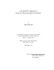
accordingly [1][2]. Fig. 1 shows a dual-core processor example.<br />
The <strong>RISC</strong> coordinates the system and per<strong>for</strong>ms some reactive<br />
tasks such as the user interface. In the meanwhile, the <strong>DSP</strong> core<br />
per<strong>for</strong>ms trans<strong>for</strong>mational tasks with more deterministic and<br />
regular behaviors, such as the small and well-defined workloads<br />
in signal processing applications. Recent <strong>RISC</strong> architectures have<br />
been enhanced <strong>for</strong> data-intensive tasks by incorporating singlecycle<br />
multiply-accumulators, SIMD (MMX-like) datapaths, or<br />
specific functional units [3] to reduce the needs <strong>for</strong> an additional<br />
core, but the per<strong>for</strong>mance is still far behind that of a <strong>DSP</strong> with<br />
similar computing resources [4]. This is because data-intensive<br />
tasks are very distinct from general-purpose computations.<br />
This work was supported by the National Science Council, Taiwan under<br />
Grant NSC93-2220-E-009-034<br />
Permission to make digital or hard copies of all or part of this work <strong>for</strong><br />
personal or classroom use is granted without fee provided that copies are<br />
not made or distributed <strong>for</strong> profit or commercial advantage and that copies<br />
bear this notice and the full citation on the first page. To copy otherwise,<br />
or republish, to post on servers or to redistribute to lists, requires prior<br />
specific permission and/or a fee.<br />
GLSVLSI’05, April 17-19, 2005, Chicago, Illinois, USA.<br />
Copyright ACM 1-59593-057-4/05/0004...$5.00.<br />
This paper presents a unified processor architecture <strong>for</strong> <strong>RISC</strong> and<br />
<strong>DSP</strong>. The processor core functions as a MIPS-like <strong>RISC</strong> in its<br />
scalar/program control mode, and it becomes a powerful <strong>DSP</strong><br />
while switched into its <strong>VLIW</strong>/data streaming mode. To maximize<br />
the utilization, most hardware resources are shared between these<br />
two modes. Moreover, the <strong>VLIW</strong>/data streaming mode has no<br />
control construct <strong>for</strong> program flow, while the data manipulation<br />
<strong>RISC</strong> instructions are executed in the <strong>VLIW</strong> datapath. The two<br />
modes can be changed instruction by instruction within a single<br />
program stream via our novel hierarchical instruction encoding,<br />
which also helps to reduce the <strong>VLIW</strong> code sizes significantly.<br />
TI OMAP <strong>Processor</strong><br />
ARM926<br />
TI C'5x<br />
<strong>DSP</strong><br />
Shared Memory Controller/DMA<br />
2D Graphics Accelerator<br />
Timer, Interrupt Controller, RTC<br />
Frame Buffer/Internal SRAM<br />
Fig. 1 Dual-core processor [2]<br />
The rest of this paper is organized as follows. Section 2 first<br />
reviews the architecture of our proprietary <strong>DSP</strong> with the novel<br />
distributed and ping-pong register organization. What follows is<br />
the unified datapath <strong>for</strong> the <strong>DSP</strong> and a MIPS-like <strong>RISC</strong>. Section<br />
3 then describes the hierarchical instruction encoding that blends<br />
the <strong>RISC</strong> and the <strong>DSP</strong> instructions into a single stream and<br />
enables the instruction-by-instruction mode switching. Moreover,<br />
the variable-length encoding scheme significantly reduces the<br />
code sizes of <strong>VLIW</strong> programs. The simulation results and our<br />
silicon implementation are available in Section 4. Section 5<br />
concludes this paper and outlines our future works.<br />
2. DATAPATH DESIGN<br />
2.1 <strong>VLIW</strong> <strong>DSP</strong> Datapath<br />
Today’s media processing demands extremely high computations<br />
with real-time constraints in audio, image or video applications.<br />
Instruction parallelism is exploited to speedup high-per<strong>for</strong>mance<br />
microprocessors. Compared to dynamically hardware-scheduled<br />
superscalar processors, <strong>VLIW</strong> machines [5] have the low-cost<br />
compiler scheduling with deterministic execution times, and thus<br />
they become the trends of high-per<strong>for</strong>mance <strong>DSP</strong> processors. But<br />
the complexity of the register file grows rapidly as more and more<br />
functional units (FU) are integrated on a chip, which concurrently<br />
operate to achieve the per<strong>for</strong>mance requirements. A centralized<br />
register file provides storage <strong>for</strong> and interconnects to each FU in a<br />
general manner and each FU can access any register location. For
N concurrent FU, the area of the centralized register file grows as<br />
N 3 , the delay as N 3/2 , and the power dissipation as N 3 [6]. Thus,<br />
the register file will soon dominate the area, the delay, and the<br />
power dissipation in the multi-issue processors as the number of<br />
FU increases. To solve this problem, the communications<br />
between FU can be restricted by partitioning the register file to<br />
significantly reduce the complexity with some per<strong>for</strong>mance<br />
penalty [7-13]. In other words, each FU can only read and write a<br />
limited subset of registers.<br />
2.1.1 Distributed and ping-pong register file<br />
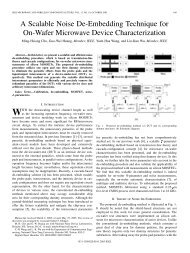
Fig. 2 shows the proposed distributed and ping-pong register file<br />
<strong>for</strong> two FU – a load/store (LS) and an arithmetic unit (AU). The<br />
32 registers are divided into four independent groups, and each<br />
group has access ports only <strong>for</strong> a single FU (two read and two<br />
write ports in our case). The eight address registers (a 0 ~a 7 ) and<br />
the eight accumulators (ac 0 ~ac 7 ) are dedicated to the LS and the<br />
AU respectively, and they are not visible to any other FU. The<br />
remnant 16 registers are shared between the two FU, and they are<br />
divided into ‘ping’ and ‘pong’ register groups. When the LS<br />
access the ping, the AU can only access the pong, and vice versa.<br />
In other words, the data registers are partitioned into two banks<br />
with exclusive accesses. In summary, each FU has 16 registers –<br />
8 registers are private and 8 registers are dynamic mapped (to be<br />
either ping or pong). The mapping is explicitly specified by the<br />
programmers in each <strong>VLIW</strong> packet as described in Section 2.1.2.<br />
address registers a0~a7<br />
Load/Store Unit (LS)<br />
ping registers d0~d7<br />
pong registers d'0~d'7<br />
Arithmetic Unit (AU)<br />
accumulators ac0~ac7<br />
Fig. 2 Distributed & ping-pong register organization<br />
Our <strong>DSP</strong> supports very powerful SIMD instructions based on the<br />
distributed and ping-pong register file. For example, the double<br />
load (store) instruction of the <strong>for</strong>m –<br />
dlw r m ,(r i )+k,(r j )+l.<br />
It per<strong>for</strong>ms two memory accesses concurrently (r m ←Mem[r i ],<br />
r m+1 ←Mem[r j ]) and simultaneous address updates (r i ←r i +k,<br />
and r j ←r j +l). The index m must be an even number with m+1<br />
implicitly specified. The double load/store instructions require<br />
six concurrent register file accesses (including two reads and four<br />
writes <strong>for</strong> dlw, or four reads and two writes <strong>for</strong> dsw). They do<br />
not cause access conflicts, because r i and r j are private address<br />
registers while r m and r m+1 are ping-pong registers that deliver<br />
data to the AU. These registers are implemented in independent<br />
banks. The AU supports 16-bit SIMD full-precision multiplyaccumulate<br />
operations with two 40-bit accumulators:<br />
fmac.d r i , r m , r n .<br />
It per<strong>for</strong>ms r i ←r i +r m .H×r n .H, and r i+1 ←r i+1 +r m .L×r n .L in<br />
parallel. Similarly, the index i must be even with i+1 implicitly<br />
specified. This SIMD instruction needs six register file accesses<br />
concurrently (four reads and two writes respectively).<br />
2.1.2 Assembly programming<br />
The syntax of the <strong>DSP</strong> assembly codes starts with the ping-pong<br />
index, followed by the instructions <strong>for</strong> each issue slot in sequence:<br />
ping-pong index; i 0 ; i 1 ;.<br />
The following is an illustrating example of a 64-tap finite-impulse<br />
response (FIR) filter that produces 1,024 outputs. Assume there is<br />
no delay slot (such as an ALU operation immediately after a load<br />
in the classical 5-stage pipeline [5]) <strong>for</strong> simplicity. The memory<br />
is byte addressable and the input and output data are 16-bit and<br />
32-bit numbers respectively.<br />
1 0; li a0,coef; li ac0,0;<br />
2 0; li a1,X; nop;<br />
3 0; li a2,Y; nop;<br />
4 rpt 1024,8;<br />
5 0; dlw d0,(a0)+4,(a1)+4; li ac1,0;<br />
6 rpt 15,2;<br />
7 1; dlw d0,(a0)+4,(a1)+4; fmac.d ac0,d0,d1;<br />
8 0; dlw d0,(a0)+4,(a1)+4; fmac.d ac0,d0,d1;<br />
9 1; dlw d0,(a0)+4,(a1)+4; fmac.d ac0,d0,d1;<br />
10 0; li a0,coef; fmac.d ac0,d0,d1;<br />
11 0; addi a1,a1,-126; add d0,ac0,ac1;<br />
12 1; sw (a2)+4,d0; li ac0,0;<br />
The zero-overhead looping instructions (RPT at line 4 and line 6)<br />
are carried out in the instruction dispatcher and do not consume<br />
any execution cycle of the datapath. The inner loop (line 7-8)<br />
loads two 16-bit inputs and two 16-bit coefficients into the 32-bit<br />
d 0 and the 32-bit d 1 with the SIMD load operations (i.e. d 0 ←<br />
Mem 32 [a 0 ] and d 1 ←Mem 32 [a 1 ]), and the address registers a 0<br />
and a 1 are updated simultaneously (i.e. a 0 ←a 0 +4 and a 1 ←a 1 +4).<br />
In the meanwhile, the AU per<strong>for</strong>ms two 16-bit MAC <strong>for</strong> two taps<br />
concurrently (i.e. ac 0 ←ac 0 +d 0 .H×d 1 .H and ac 1 ←ac 1 +d 0 .L×<br />
d 1 .L). After accumulating 32 32-bit products respectively with<br />
two 40-bit accumulators, ac 0 are ac 1 are added together and<br />
rounded back to the 32-bit d 0 in the ping-pong registers. Finally,<br />
the 32-bit output is stored in the memory by the LS via d 0 . In this<br />
FIR example, an output requires 35 cycles or the <strong>DSP</strong> can<br />
compute 1.83 taps per cycle. Note that, the loops can be unrolled<br />
to achieve similar per<strong>for</strong>mance easily if the load slots are taken<br />
into account. By the way, the ping-pong register organization<br />
helps to reduce the code size, <strong>for</strong> the programmer can specify<br />
different register locations (i.e. to be either in ping or pong) with<br />
the same name via the ping-pong index. We will make use of this<br />
property in the instruction encoding later in Section 3.<br />
2.2 <strong>Unified</strong> <strong>RISC</strong> & <strong>VLIW</strong> <strong>DSP</strong><br />
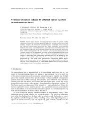
Each register group in Fig. 2 is actually implemented with two<br />
2R/1W (two reads and 1 write) register banks of half sizes (i.e. 4<br />
registers) as shown in the <strong>VLIW</strong> block in Fig.3, instead of 2R/2W<br />
access ports. Since a <strong>RISC</strong> core does not contain any data<br />
manipulation instruction other than those per<strong>for</strong>med on the LS (i.e.<br />
load/store instructions) or the AU (i.e. ALU instructions), the<br />
extra resource <strong>for</strong> the <strong>DSP</strong> datapath to execute <strong>RISC</strong> instructions<br />
is an additional register file. To simplify data exchange between<br />
the two modes, the ping-pong data registers are aliased as the<br />
‘saved’ (s 0 ~s 7 ) and the ‘temporary’ (t 0 ~t 7 ) data registers in the<br />
MIPS-compatible scalar/program control mode. The remnant 16
egisters are private to the scalar mode (actually, there are only 15<br />
physical registers, <strong>for</strong> r 0 is hardwired to zero [5]). Fig. 3 shows<br />
the unified datapath <strong>for</strong> the two modes with total nine 2R/1W<br />
register banks.<br />
<strong>VLIW</strong> / Data Streaming<br />
address registers a0~a7<br />
even odd<br />
For applications demanding even higher per<strong>for</strong>mance, the unified<br />
processor core can integrate three more <strong>DSP</strong> datapaths (up to four<br />
clusters). Our first prototype described hereafter contains two<br />
clusters – a main cluster as shown in Fig. 3 and a slave cluster as<br />
shown in Fig. 2. In other words, it can be configured as a MIPSlike<br />
<strong>RISC</strong> or a 4-way <strong>VLIW</strong> <strong>DSP</strong>. For most cases, programmers<br />
can exploit the data-level parallelism and arrange the two clusters<br />
to operate independently. Otherwise, inter-cluster communication<br />
can be per<strong>for</strong>med via the memory subsystem.<br />
Scalar /<br />
Program Control<br />
scalar registers<br />
r0~r7;<br />
r24~r31<br />
LS<br />
ping registers d0~d7<br />
even odd<br />
pong registers d'0~d'7<br />
even odd<br />
AU<br />
3. HIERARCHICAL INSTRUCTION<br />
ENCODING<br />
The unified processor core is able to change its operation modes<br />
instruction by instruction within a single program stream. This<br />
section will describe the enabling technology – the hierarchical<br />
instruction encoding, which also helps to reduce the <strong>VLIW</strong> code<br />
sizes significantly.<br />
accumulator ac0~ac7<br />
even odd<br />
Fig. 3 <strong>Unified</strong> datapath <strong>for</strong> <strong>RISC</strong> & <strong>DSP</strong><br />
Fig. 4 shows the add/sub instructions of the unified processor core<br />
and the relationship with those of the MIPS32 ISA. The first<br />
column shows the MIPS add/sub instructions, where the gray ones<br />
denote pseudo instructions. The 2nd column lists the equivalent<br />
instructions of the scalar/program control mode, and the 3rd and<br />
the 4th columns summarize those of the <strong>VLIW</strong>/data streaming<br />
mode. Note that C compilers do not generate MIPS codes with<br />
addi, add, sub, and neg (i.e. those cause overflow exceptions),<br />
and thus our processor do not support these instructions. Besides,<br />
few pseudo MIPS instructions are mapped to physical instructions.<br />
Finally, the data manipulation instructions of the scalar mode are<br />
actually executed in the <strong>DSP</strong> datapath, which are highlighted in<br />
the yellow background.<br />
<strong>VLIW</strong><br />
MIPS Scalar<br />
AU LS<br />
addiu addi addi addi<br />
addu add add add<br />
subu sub sub sub<br />
addi NA NA NA<br />
add NA NA NA<br />
sub NA NA NA<br />
neg NA NA NA<br />
negu neg neg neg<br />
nop nop nop nop<br />
abs abs abs abs<br />
rsbi rsbi<br />
addi.d addi.d<br />
add.d add.d<br />
sub.d sub.d<br />
abs.d abs.d<br />
addi.q addi.q<br />
add.q add.q<br />
sub.q sub.q<br />
bf.d<br />
saa.q<br />
Fig. 4 Add/sub instructions<br />
3.1 <strong>VLIW</strong>/Data Streaming Mode<br />
<strong>VLIW</strong> processors are notorious <strong>for</strong> their poor code density. It<br />
comes from the redundancy inside (1) the fixed-length <strong>RISC</strong>-like<br />
instructions, where most operations need not all the control bits<br />
actually, (2) the position-coded <strong>VLIW</strong> packet, where the unused<br />
instruction slots must be filled by NOP, and (3) the repeated codes<br />
due to loop unrolling or software pipelining. HAT [14] is an<br />
efficient variable-length instruction <strong>for</strong>mat to solve the first<br />
problem. Variable-length <strong>VLIW</strong> [10] eliminates the NOP by<br />
attaching a dispatch code to each instruction <strong>for</strong> run-time dispatch<br />
and decoding. Moreover, specific marks are required to indicate<br />
the boundaries of the variable-length <strong>VLIW</strong> packets (i.e. with a<br />
varying number of effective instructions). Indirect <strong>VLIW</strong> [15]<br />
uses an addressable internal micro-instruction memory <strong>for</strong> the<br />
<strong>VLIW</strong> datapath (i.e. the programmable VIM), and the <strong>VLIW</strong><br />
packets are executed with only very short indices. The <strong>RISC</strong>-like<br />
instructions in the existing packets can be reused to synthesize<br />
new packets to reduce the instruction bandwidth. Systemonic<br />
proposes an incremental encoding scheme <strong>for</strong> the prolog and the<br />
epilog of the software pipelined codes [16] to remove the repeated<br />
codes. In this paper, we propose a novel hierarchical instruction<br />
encoding, which takes into account all the three causes to improve<br />
the <strong>VLIW</strong> code density.<br />
3.1.1 Variable-length instructions<br />
add/sub<br />
00000<br />
addi/rsbi<br />
1000<br />
abs<br />
01000<br />
bf.d<br />
00100<br />
saa.q<br />
00100<br />
Head (20-bit)<br />
Tail (0~28-bit)<br />
func rd rs rt<br />
func: 000(add), 001(add.d), 010(add.q)<br />
100(sub), 101(sub.d), 110(sub.q)<br />
func DL rd rs imm.L imm.H<br />
func: 00(addi), 01(addi.d), 10(rsbi), 11(rsbi.d)<br />
DL(immediate length): 00(4-bit), 01(8-bit), 10(16-bit), 11(32-bit)<br />
f u rd rs<br />
100<br />
001<br />
rd rs rt<br />
rd rs rt<br />
unused<br />
f: 0(abs), 1(abs.d)<br />
Fig. 5 Machine codes <strong>for</strong> add/sub instructions
Fig. 5 shows the variable-length encoding of the AU instructions<br />
listed in Fig. 4. The code length of an instruction depends on the<br />
number of its operands and the frequency of its usage. The<br />
variable-length code is divided into a fixed-length ‘head’ and the<br />
remnant variable-length ‘tail’ as HAT <strong>for</strong>mat [14]. This helps to<br />
improve the regularity, and reduces the complexity <strong>for</strong> instruction<br />
alignment significantly.<br />
3.1.2 <strong>VLIW</strong> packets without NOP<br />
The effective instructions <strong>for</strong> an execution cycle (i.e. without NOP)<br />
are packed into a <strong>VLIW</strong> packet with a fixed-length ‘CAP’. The<br />
CAP has a ‘valid’ field, where each functional unit (FU) has a<br />
corresponding bit to indicate whether it is idle. In other words,<br />
the NOP is eliminated by turning the corresponding valid bit off.<br />
Fig. 6(a) shows the 14-bit CAP <strong>for</strong>mat of our prototype with 4-<br />
way <strong>VLIW</strong>. As the example given in Fig. 6(b), the two addi<br />
instructions are first translated into the machine codes by looking<br />
up Fig.5. The 14-bit CAP is set as 00 <strong>for</strong> <strong>VLIW</strong> instruction,<br />
0101 to remove NOP in the 1st and the 3rd slots, 0010 <strong>for</strong> total<br />
8-bit tails, 00 <strong>for</strong> the ping-pong indices of the two clusters, and<br />
the ending 00 to disable the SIMD-cluster mode and the<br />
conditional executions.<br />
2-bit 4-bit 4-bit 2-bit<br />
M<br />
Valid Tail Length PP<br />
00: <strong>VLIW</strong>/data streaming mode<br />
11: Scalar/program control mode<br />
01: Differential encoding (<strong>for</strong> <strong>VLIW</strong>)<br />
10: End of bundle<br />
(a)<br />
e.g. 00 nop; addi d0,ac4,64; nop; addi d0,ac4,64;<br />
Cap<br />
H1<br />
H3<br />
00<br />
0101 0010 00<br />
0 0<br />
1000 00 01 1000 0100 0000<br />
1000 00 01 1000 0100 0000<br />
S<br />
C<br />
Conditional execution<br />
SIMD encoding<br />
T1<br />
T3<br />
0100<br />
0100<br />
Fig. 6 Instruction packet <strong>for</strong> a 4-way <strong>VLIW</strong> (with 2 clusters)<br />
For an N-way <strong>VLIW</strong> processor, our approach uses only N ‘valid’<br />
bits to remove NOP in a packet. Variable-length <strong>VLIW</strong> either<br />
uses log 2 (N+1) bits <strong>for</strong> a <strong>VLIW</strong> packet to indicate the number of<br />
active issue slots, or one bit <strong>for</strong> each effective instruction to<br />
indicate the packet boundary. Moreover, additional log 2 N bits are<br />
required <strong>for</strong> each instruction to dispatch it to the correspondent<br />
slot. Assume a packet has P instructions in average (0≤P≤N), and<br />
Variable-length <strong>VLIW</strong> needs log 2 (N+1)+Plog 2 N or P(log 2 N+1)<br />
bits <strong>for</strong> a packet accordingly. There<strong>for</strong>e, it has better compression<br />
only <strong>for</strong> codes with very low parallelism (i.e. with small P).<br />
In the <strong>VLIW</strong>/data streaming mode, the clusters can be configured<br />
into SIMD execution by turning on the S bit in the CAP. The<br />
instructions of the main cluster will be replicated to all clusters to<br />
reduce to code sizes. For the example in Fig. 6(b), 24 bits can be<br />
saved by setting S=1 in the CAP. Moreover, the hierarchical<br />
encoding supports the differential mode using a CAP starting with<br />
01. The <strong>VLIW</strong> packet of the previous execution cycle will be<br />
reused with small updates, such as the ping-pong indices, the<br />
destination register <strong>for</strong> the load instructions, and the source<br />
registers <strong>for</strong> the multiply-accumulate instructions, etc. Finally, all<br />
instructions can be conditionally executed by turning on the C bit<br />
in the CAP.<br />
3.1.3 Instruction Bundle<br />
The variable-length <strong>VLIW</strong> packets are packed into fixed length<br />
instruction bundles to simplify the instruction memory accesses.<br />
In order to pipeline the instruction fetch, alignment, and decoding,<br />
the fixed-length CAP and the variable-length <strong>VLIW</strong> packet are<br />
placed from the two ends of an instruction bundle respectively as<br />
depicted in Fig. 7. For each <strong>VLIW</strong> packet, the fixed-length heads<br />
are placed in order ahead of the variable-length tails. By the way,<br />
because the CAP is fixed-length and placed in order, instruction<br />
look-ahead is possible to reduce the control overheads.<br />
14-bit<br />
Cap<br />
512-bit instruction bundle<br />
T3<br />
T1<br />
instruction packet<br />
Fig. 7 Instruction bundle<br />
An instruction bundle contains various numbers of <strong>VLIW</strong> packets,<br />
and the code 10 of the leading two bits of the CAP is reserved to<br />
denote the bundle end. The total length of the tails is attached in<br />
the CAP to locate the next <strong>VLIW</strong> packet in the pipelined<br />
instruction aligner. Finally, depending on the implementations of<br />
the instruction aligners described later and our simulations of real<br />
programs, the 512-bit instruction bundles are optimal, which have<br />
practical decoder complexity and acceptable fragment (i.e. unused<br />
bits in a bundle).<br />
3.2 Scalar/Program Control Mode<br />
The scalar instructions are also variable-length encoded, which<br />
are similar to those depicted in Fig. 5. But a scalar instruction is<br />
decomposed into a fixed-length CAP with leading 11 (instead of<br />
head) and a variable-length tail <strong>for</strong> the remnant bits. The branch<br />
instructions change the program flow to a new instruction bundle<br />
with the packet index. To easily locate the target <strong>VLIW</strong> packet,<br />
the pointer <strong>for</strong> its first instruction head is also encoded in the<br />
branch instructions. Our first prototype contains a 16KByte onchip<br />
instruction memory, which is equal to a page of 256 bundles.<br />
3.3 Decoder <strong>Architecture</strong><br />
To extract from an instruction bundle the appropriate bit fields <strong>for</strong><br />
decoding is very complicated, especially <strong>for</strong> the variable-length<br />
<strong>VLIW</strong> packets. Instead of huge multiplexers, we use incremental<br />
and logarithmic shifters <strong>for</strong> instruction alignment, as depicted in<br />
Fig. 8. The <strong>VLIW</strong> packets are continuously shifted out from the<br />
two ends of an instruction bundle, and the decoders can operate<br />
on the fixed positions. The lengths of the two buffers can be<br />
calculated as follows.<br />
⎡ bundle size ⎤<br />
HT buffer size = bundle size - CAP size×<br />
max instr length<br />
⎢<br />
⎥<br />
⎡512⎤<br />
= 512 −14×<br />
= 456 (bits)<br />
⎢170<br />
⎥<br />
⎡ bundle size ⎤<br />
CAP buffer size = CAP size×<br />
average scalar length<br />
⎢<br />
⎥<br />
⎡512⎤<br />
= 14×<br />
= 280 (bits)<br />
⎢ 26<br />
⎥<br />
H3<br />
H1
The buffer size <strong>for</strong> heads and tails (HT) is the bundle size minus<br />
the bits impossible to be HT (i.e. the minimum number of <strong>VLIW</strong><br />
packets in a bundle multiplied by the fixed length of CAP). The<br />
CAP buffer size can be estimated using the average number of<br />
instructions in a bundle when the processor stays in the scalar/<br />
program control mode. Note that the CAP and the HT buffers<br />
contain overlapped bits, because the boundary between CAP and<br />
HT is not deterministic.<br />
Cap shifter (14-bit)<br />
Cap buffer (280-bit)<br />
14+2<br />
280<br />
Coarse<br />
branch shifter<br />
(0~266-bit)<br />
Cap decoder<br />
280<br />
16KByte On-Chip Instruction Memory<br />
(including 256 instruction bundles)<br />
456<br />
Coarse<br />
branch shifter<br />
(0~452-bit)<br />
H0 shifter (20-bit)<br />
H1 shifter (20-bit)<br />
H2 shifter (20-bit)<br />
H3 shifter (20-bit)<br />
Tail & fine branch shifter (0~60-bit)<br />
456<br />
HT buffer (456-bit)<br />
Fig. 8 Instruction aligner<br />
456<br />
20<br />
20<br />
20<br />
20<br />
60<br />
Head<br />
decoder<br />
Tail<br />
decoder<br />
The CAP decoder only examines the leading 16 bits of the 280-bit<br />
buffer and shifts out a 14-bit CAP each cycle. Then, the four<br />
incremental shifters at the right-hand-side Fig. 8 shift out the 20-<br />
bit fixed-length heads depending on the ‘valid’ bits in the CAP.<br />
The logarithmic tail shifter follows to shift out all tails of a <strong>VLIW</strong><br />
packet. There<strong>for</strong>e, the HT buffer will be aligned to the next<br />
<strong>VLIW</strong> packet as the CAP buffer. Finally, two coarse logarithmic<br />
shifters are added <strong>for</strong> branches to align a new bundle with the<br />
index and the packet pointer respectively.<br />
4. RESULTS<br />
We have completely verified the proposed Packed Instruction &<br />
Clustered <strong>Architecture</strong> (Pica) from the instruction set simulation<br />
in C++, the micro-architecture design in cycle-accurate SystemC,<br />
to FPGA prototyping and the cell-based silicon implementation.<br />
This section will summarize the remarkable results.<br />
4.1 Instruction Set Simulation<br />
We have hand-coded several <strong>DSP</strong> kernels in assembly to evaluate<br />
the per<strong>for</strong>mance of the processor core with our instruction set<br />
simulator. Table I summarizes the per<strong>for</strong>mance comparisons<br />
between the state-of-the-art high-per<strong>for</strong>mance <strong>DSP</strong> processors<br />
and Pica <strong>DSP</strong>. The second row shows the number of cycles<br />
required <strong>for</strong> N-sample T-tap FIR filtering on 16-bit samples,<br />
which reveals the on-chip MAC resources. The third row<br />
compares the number of execution cycles to per<strong>for</strong>m 2-D discrete<br />
cosine trans<strong>for</strong>m (DCT). The fourth row lists the per<strong>for</strong>mance of<br />
the 256-point radix-2 fast Fourier trans<strong>for</strong>m (FFT), which is also<br />
measured in the execution cycles. Finally, the last row compares<br />
the per<strong>for</strong>mance of the motion estimation under the MAE (mean<br />
absolute error) criteria. The block size is 16×16 and the search<br />
range is within ±15 pixels. The simulation results show that the<br />
per<strong>for</strong>mance of our proposed <strong>DSP</strong> processor is comparable with<br />
the state-of-the-art <strong>DSP</strong> <strong>for</strong> various benchmarks once the dataflow<br />
is appropriately arranged through the ping-pong register file.<br />
Table I. Per<strong>for</strong>mance comparison on various <strong>DSP</strong> kernels<br />
TI C64<br />
[10]<br />
TI C55<br />
[17]<br />
NEC<br />
SPXK5 [18]<br />
Intel/ADI<br />
MSA [19]<br />
Pica<br />
FIR NT/4 NT/2 NT/2 NT/2 NT/4<br />
DCT 126 238 240 296 127<br />
FFT 2,403 4,768 2,944 3,176 2,510<br />
ME 36,538 82,260 - 90,550 41,372<br />
(Unit: cycle)<br />
Table II summarizes the per<strong>for</strong>mance of Pica <strong>for</strong> JPEG still image<br />
compression [20]. Two 512×512-pixel color images – Lena and<br />
Baboon are used in this simulation. The JPEG program written in<br />
C is first compiled onto Pica in its MIPS-like scalar/program<br />
control mode with a proprietary compiler modified from the GNU<br />
tool. The execution cycles are listed in the 2nd and the 3rd<br />
columns. Then, the four kernels are hand-coded and optimized<br />
<strong>for</strong> the <strong>VLIW</strong>/data streaming mode, and the results are given in<br />
the 4th and the 5th columns. Note that the per<strong>for</strong>mance can be<br />
significantly improved by a factor of 10~15.<br />
Table II. Per<strong>for</strong>mance evaluation of JPEG<br />
Pica (scalar only) Pica (dual-mode)<br />
Lena Baboon Lena Baboon<br />
RGB to YCbCr 33,734,912 487,066<br />
DCT 11,181,312 850,946<br />
Q & RLC 12,491,008 1,187,849<br />
Huffman 6,441,701 12,997,472 1,814,286 3,800,285<br />
Total 63,848,933 70,404,704 4,340,149 6,326,148<br />
(Unit: cycle)<br />
Finally, three instruction encoding schemes are compared using<br />
the above application programs, and the results are given in Table<br />
III. The fixed-length encoding uses 152 bits <strong>for</strong> a <strong>VLIW</strong> packet,<br />
where an AU instruction occupies 36 bits and an LS instruction<br />
needs 40 bits respectively. The scalar version of JPEG (JPEG_S)<br />
is exceptional, of which the encoding follows the standard 32-bit<br />
MIPS instructions. The variable-length <strong>VLIW</strong> encoding follows<br />
the approach by TI [10]. The instructions are first encoded as 40-<br />
bit words, and each of them are attached with 1 bit <strong>for</strong> packet<br />
boundary and 2 bits <strong>for</strong> dispatch. There<strong>for</strong>e, every effective<br />
instruction requires 43 bits. Finally, all programs are encoded<br />
with our hierarchical instruction encoding. The effective<br />
instruction bits and the memory requirements while packed into<br />
512-bit bundles are both shown in the table. Note that the handoptimized<br />
JPEG with almost 15× per<strong>for</strong>mance requires less<br />
instruction memory after the proposed instruction encoding.<br />
Table III. Code size comparison<br />
Fixedlengtlength<br />
Effective<br />
Variable-<br />
Hierarchical<br />
Bundled<br />
FIR 5,016 4,559 1,742 1,834<br />
DCT 10,944 9,588 3,840 4,226<br />
FFT 60,648 50,760 20,946 22,258<br />
ME 12,160 10,669 3,948 4,146<br />
JPEG_S 36,096* - 26,690 27,521<br />
JPEG 62,472 42,253 19,654 20,666<br />
* 32-bit fixed-length <strong>RISC</strong> instructions (Unit: bit)
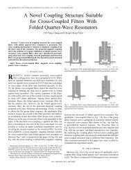
4.2 Silicon Implementation<br />
We have implemented the unified processor core in Verilog RTL,<br />
which is cross-verified with the cycle-accurate SystemC model to<br />
achieve 100% code coverage. The design is synthesized using<br />
Physical Compiler from Synopsys with the 0.18um cell library<br />
from Artisan. The net-lists are then placed and routed using SoC<br />
Encounter from Cadence <strong>for</strong> the UMC 1P6M CMOS technology.<br />
Fig. 9 shows the layout of the proposed unified processor core<br />
with on-chip 16-Kbyte data and 16-Kbyte instruction memories.<br />
Its gate count is 643,952 (343,284 <strong>for</strong> core only) and the core area<br />
is 3.23mm×3.23mm. The processor has a nine-stage pipeline (4<br />
stages <strong>for</strong> instruction dispatch and 5 stages <strong>for</strong> execution), and it<br />
can operate at 208 MHz and consume 380.6mW average power<br />
(running 2-D DCT).<br />
Main Cluster<br />
Instrunction Memory<br />
Instruction Dispatcher<br />
Scalar<br />
RF<br />
Distributed &<br />
Ping-Pong RF<br />
Data Memory<br />
Cluster 1<br />
Distributed &<br />
Ping-Pong RF<br />
Fig. 9 Layout of the unified processor core<br />
5. CONCLUSIONS<br />
This paper presents the design and the silicon implementation of a<br />
unified processor core <strong>for</strong> <strong>RISC</strong> and scalable <strong>VLIW</strong> <strong>DSP</strong>. The<br />
two modes can be changed instruction by instruction within a<br />
single program stream via the hierarchical instruction encoding,<br />
which also helps to reduce the code sizes. In order to minimize<br />
the hardware resources, the <strong>DSP</strong> has no control construct <strong>for</strong><br />
program flow, and the data manipulation <strong>RISC</strong> instructions are<br />
per<strong>for</strong>med by <strong>DSP</strong>. Besides the general applications as the dualcore<br />
multimedia systems, new application programs can be easily<br />
targeted on its compiler-friendly <strong>RISC</strong> mode and the per<strong>for</strong>mance<br />
is then improved by selectively optimizing the kernels on the <strong>DSP</strong><br />
mode. The tightly-coupled operation modes make such design<br />
strategy much more straight<strong>for</strong>ward and efficient. We are now<br />
studying the code optimization techniques <strong>for</strong> the distributed and<br />
ping-pong register file and developing a single-pass automatic<br />
code generator <strong>for</strong> the two modes of the unified processor core.<br />
6. REFERENCES<br />
[1] Intel PXA800F Cellular <strong>Processor</strong> – Development Manual, Intel<br />
Corp., Feb. 2003<br />
[2] OMAP5910 Dual Core <strong>Processor</strong> – Technical Reference Manual,<br />
Texas Instruments, Jan. 2003<br />
[3] M. Levy, “ARM picks up per<strong>for</strong>mance,” Microprocessor Report,<br />
4/7/03-01<br />
[4] R. A. Quinnell, “Logical combination? Convergence products<br />
need both <strong>RISC</strong> and <strong>DSP</strong> processors, but merging them may not<br />
be the answer,” EDN, 1/23/2003<br />
[5] J. L Hennessy, and D. A. Patterson, Computer <strong>Architecture</strong> – A<br />
Quantitative Approach, 3rd Edition, Morgan Kaufmann, 2002<br />
[6] S. Rixner, W. J. Dally, B. Khailany, P. Mattson, U. J. Kapasi,<br />
and J. D. Owens, “Register organization <strong>for</strong> media processing,”<br />
in Proc. HPCA-6, 2000, pp.375-386<br />
[7] J. Zalamea, J. Llosa, E. Ayguade, and M. Valero, “Hierarchical<br />
clustered register file organization <strong>for</strong> <strong>VLIW</strong> processors,” in<br />
Proc. IPDPS, 2003, pp.77-86<br />
[8] P. Faraboschi, G. Brown, J. A. Fisher, G. Desoll, and F. M. O.<br />
Homewood, “Lx: a technology plat<strong>for</strong>m <strong>for</strong> customizable <strong>VLIW</strong><br />
embedded processing,” in Proc. ISCA, 2000, pp.203-213<br />
[9] E. F. Barry, G. G. Pechanek, and P. R. Marchand, “Register file<br />
indexing methods and apparatus <strong>for</strong> providing indirect control of<br />
register file addressing in a <strong>VLIW</strong> processor,” International<br />
Application Published under the Patent Cooperation Treaty<br />
(PCT), WO 00/54144, Mar. 9 2000<br />
[10] TMS320C64x <strong>DSP</strong> Library Programmer's Reference, Texas<br />
Instruments Inc., Apr 2002<br />
[11] K. Arora, H. Sharangpani, and R. Gupta, “Copied register files<br />
<strong>for</strong> data processors having many execution units” U.S. Patent<br />
6,629,232, Sep. 30, 2003<br />
[12] A. Kowalczyk et al., “The first MAJC microprocessor: a dual<br />
CPU system-on-a-chip,” IEEE J. Solid-State Circuits, vol. 36,<br />
pp.1609-1616, Nov. 2001<br />
[13] A. Terechko, E. L. Thenaff, M. Garg, J. Eijndhoven, and H.<br />
Corporaal, “Inter-cluster communication models <strong>for</strong> clustered<br />
<strong>VLIW</strong> processors,” in Proc. HPCA-9, 2003, pp.354-364<br />
[14] H. Pan and K. Asanovic, “Heads and tails: a variable-length<br />
instruction <strong>for</strong>mat supporting parallel fetch and decode,” in Proc.<br />
CASES, 2001<br />
[15] G. G. Pechanek and S. Vassiliadis, “The ManArray embedded<br />
processor architecture,” Euromicro Conf., vol.1, pp.348-355,<br />
Sep., 2000<br />
[16] G. Fettweis, M. Bolle, J. Kneip, and M. Weiss, “On<strong>DSP</strong>: a new<br />
architecture <strong>for</strong> wireless LAN applications,” Embedded<br />
<strong>Processor</strong> Forum, May 2002<br />
[17] TMS320C55x <strong>DSP</strong> Programmer’s Guide, Texas Instruments Inc.,<br />
July 2000<br />
[18] T. Kumura, M. Ikekawa, M. Yoshida, and I. Kuroda, “<strong>VLIW</strong><br />
<strong>DSP</strong> <strong>for</strong> mobile applications,” IEEE Signal Processing Mag.,<br />
pp.10-21, July 2002<br />
[19] R. K. Kolagotla, et al, “A 333-MHz dual-MAC <strong>DSP</strong> architecture<br />
<strong>for</strong> next-generation wireless applications,” in Proc. ICASSP,<br />
2001, pp.1013-1016<br />
[20] W. B. Pennebaker and J. L. Mitchell, JPEG – Still Image Data<br />
Compression Standard, Van Nostrand Reinhold, 1993<br />
[21] T. J. Lin, C. C. Chang, C. C. Lee, and C. W. Jen, “An efficient<br />
<strong>VLIW</strong> <strong>DSP</strong> architecture <strong>for</strong> baseband processing,” in Proc.<br />
ICCD, 2003<br />
[22] P. Lapsley, J. Bier, A. Shoham, and E. A. Lee, <strong>DSP</strong> <strong>Processor</strong><br />
Fundamentals – <strong>Architecture</strong>s and Features, IEEE Press, 1996<br />
[23] TriCore 2-32-bit <strong>Unified</strong> <strong>Processor</strong> Core v.2.0 <strong>Architecture</strong> –<br />
<strong>Architecture</strong> Manual, Infineon Technology, June 2003<br />
[24] Y. H. Hu, Programmable Digital Signal <strong>Processor</strong>s –<br />
<strong>Architecture</strong>, Programming, and Applications, Marcel Dekker<br />
Inc., 2002