
You also want an ePaper? Increase the reach of your titles
YUMPU automatically turns print PDFs into web optimized ePapers that Google loves.
3.5MPa<br />
7 MPa<br />
14 MPa<br />
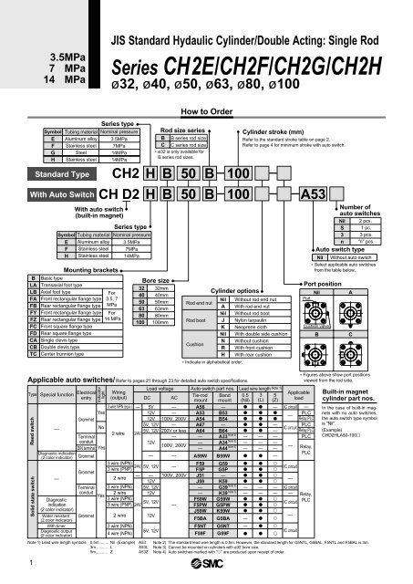
JIS Standard Hydaulic Cylinder/Double Acting: Single Rod<br />
Series <strong>CH2</strong>E/<strong>CH2</strong>F/<strong>CH2</strong>G/<strong>CH2</strong>H<br />
ø32, ø40, ø50, ø63, ø80, ø100<br />
B<br />
LA<br />
LB<br />
FA<br />
FB<br />
FY<br />
FZ<br />
FC<br />
FD<br />
CA<br />
CB<br />
TC<br />
Applicable auto switches/<br />
Type<br />
Reed switch<br />
Solid state switch<br />
1<br />
Symbol<br />
E<br />
F<br />
G<br />
H<br />
Special function<br />
Electrical<br />
entry<br />
—<br />
Diagnostic indication<br />
(2 color indicator)<br />
—<br />
Tubing material<br />
Aluminum alloy<br />
Stainless steel<br />
Steel<br />
Stainless steel<br />
Standard Type<br />
With Auto Switch<br />
Symbol<br />
E<br />
F<br />
H<br />
Basic type<br />
Transaxial foot type<br />
Axial foot type<br />
Front rectangular flange type<br />
Rear rectangular flange type<br />
Front rectangular flange type<br />
Rear rectangular flange type<br />
Front square flange type<br />
Rear square flange type<br />
Single clevis type<br />
Double clevis type<br />
Center trunnion type<br />
Terminal<br />
conduit<br />
DIN terminal Yes<br />
Terminal<br />
conduit<br />
Diagnostic<br />
indication<br />
(2 color indicator)<br />
Water resistant Grommet<br />
(2 color indicator)<br />
With timer<br />
Diagnostic output<br />
(2 color indicator)<br />
<strong>CH2</strong> H<br />
CH D2 H<br />
Indicator<br />
light<br />
No<br />
Yes<br />
2 wire<br />
3 wire (NPN)<br />
3 wire (PNP)<br />
2 wire<br />
3 wire (NPN)<br />
2 wire<br />
3 wire (NPN)<br />
3 wire (PNP)<br />
2 wire<br />
3 wire (NPN)<br />
4 wire (NPN)<br />
32<br />
40<br />
50<br />
63<br />
80<br />
100<br />
3 wire NPN (equiv.) —<br />
Yes<br />
Grommet<br />
Grommet<br />
Grommet<br />
Series type<br />
Mounting brackets<br />
Nominal pressure<br />
3.5MPa<br />
7MPa<br />
14MPa<br />
14MPa<br />
With auto switch<br />
(built-in magnet)<br />
Tubing material<br />
Aluminum alloy<br />
Stainless steel<br />
Stainless steel<br />
For<br />
3.5, 7<br />
MPa<br />
For<br />
14 MPa<br />
Series type<br />
Nominal pressure<br />
3.5MPa<br />
7MPa<br />
14MPa<br />
Wiring<br />
(output)<br />
24V<br />
Note 1) Lead wire length symbols 0.5m ........ Nil (Example) A53<br />
3m .......... L A53L<br />
5m........... Z A53Z<br />
Bore size<br />
How to Order<br />
B 50 B 100<br />
B 50 B 100 A53<br />
32mm<br />
40mm<br />
50mm<br />
63mm<br />
80mm<br />
100mm<br />
Refer to pages 21 through 23 for detailed auto switch specifications.<br />
Load voltage<br />
DC<br />
5V<br />
12V<br />
12V<br />
5V, 12V<br />
5V, 12V<br />
12V<br />
—<br />
AC<br />
—<br />
—<br />
100V, 200V<br />
—<br />
200V or less<br />
—<br />
100V, 200V<br />
—<br />
24V 5V, 12V —<br />
— —<br />
12V<br />
5V, 12V<br />
12V<br />
100V, 200V<br />
5V, 12V<br />
24V<br />
—<br />
12V<br />
5V, 12V<br />
Rod size series<br />
B B series rod size<br />
C C series rod size<br />
∗ ø32 is only available for<br />
B series rod sizes.<br />
Rod end nut<br />
Rod boot<br />
Cushion<br />
Auto switch part nos.<br />
Tie-rod<br />
mount<br />
A56<br />
A53<br />
A54<br />
A67<br />
A64<br />
—<br />
—<br />
—<br />
A59W<br />
F59<br />
F5P<br />
J51<br />
J59<br />
—<br />
—<br />
F59W<br />
F5PW<br />
J59W<br />
F5BA<br />
F5NT<br />
F59F<br />
Cylinder options<br />
Nil<br />
A<br />
Nil<br />
J<br />
K<br />
Nil<br />
N<br />
R<br />
H<br />
∗ Indicate in alphabetical order.<br />
Band<br />
mount<br />
—<br />
B53<br />
B54<br />
—<br />
B64<br />
A33<br />
A34<br />
A44<br />
B59W<br />
G59<br />
G5P<br />
—<br />
K59<br />
G39<br />
K39<br />
G59W<br />
G5PW<br />
K59W<br />
G5BA<br />
G5NT<br />
G59F<br />
Note 3)<br />
Note 3)<br />
Note 3)<br />
Note 3)<br />
Note 3)<br />
Cylinder stroke (mm)<br />
Refer to the standard stroke table on page 2.<br />
Refer to page 4 for minimum stroke with auto switch.<br />
Without rod end nut<br />
With rod end nut<br />
Without rod boot<br />
Nylon tarpaulin<br />
Neoprene cloth<br />
With double side cushion<br />
Without cushion<br />
With front cushion<br />
With rear cushion<br />
Lead wire length Note 1)<br />
0.5<br />
(Nil)<br />
<br />
<br />
<br />
<br />
<br />
—<br />
—<br />
—<br />
<br />
<br />
<br />
<br />
<br />
—<br />
—<br />
<br />
<br />
<br />
—<br />
—<br />
<br />
3<br />
(L)<br />
<br />
<br />
<br />
<br />
<br />
—<br />
—<br />
—<br />
<br />
<br />
<br />
<br />
<br />
—<br />
—<br />
<br />
<br />
<br />
<br />
<br />
<br />
5<br />
(Z)<br />
—<br />
<br />
<br />
—<br />
—<br />
—<br />
—<br />
—<br />
—<br />
<br />
<br />
<br />
<br />
—<br />
—<br />
<br />
<br />
<br />
<br />
<br />
<br />
Applicable<br />
load<br />
IC circuit<br />
—<br />
IC circuit<br />
—<br />
IC circuit<br />
—<br />
IC circuit<br />
—<br />
IC circuit<br />
—<br />
IC circuit<br />
Port position<br />
—<br />
PLC<br />
Relay,PLC<br />
PLC<br />
Relay,PLC<br />
PLC<br />
Relay,<br />
PLC<br />
Relay,<br />
PLC<br />
Note 2) The standard lead wire length is 0.5m. However, the standard length for G5NTL, G5BAL, F5NTL and F5BAL is 3m.<br />
Note 3) Cannot be mounted on <strong>cylinder</strong>s with ø32 bore size.<br />
Note 4) Auto switches marked with "" are produced upon receipt of order.<br />
Port<br />
Number of<br />
auto switches<br />
Nil 2 pcs.<br />
S 1 pc.<br />
3 3 pcs.<br />
n "n" pcs.<br />
Auto switch type<br />
Nil<br />
Cushion valve<br />
B<br />
Nil<br />
Without auto switch<br />
∗ Select applicable auto switches<br />
from the table below.<br />
A<br />
C<br />
∗ Figures above show port positions<br />
viewed from the rod side.<br />
Built-in magnet<br />
<strong>cylinder</strong> part nos.<br />
In the case of built-in magnets<br />
with no auto switches,<br />
the auto switch type symbol<br />
is "Nil".<br />
(Example)<br />
CHD2HLA50-100