
You also want an ePaper? Increase the reach of your titles
YUMPU automatically turns print PDFs into web optimized ePapers that Google loves.
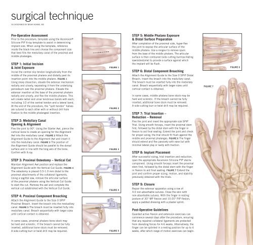
<strong>surgical</strong> <strong>technique</strong><br />
As described by brian adams, MD<br />
Pre-Operative Assessment<br />
Prior to the procedure, template using the Ascension ®<br />
Silicone PIP X-ray template to assist in determining<br />
implant size. When using the template, reference<br />
inside the black line and choose the component size<br />
that best fills the medullary canal of the proximal and<br />
middle phalanges.<br />
STEP 1: Initial Incision<br />
& Joint Exposure<br />
Incise the central slip tendon longitudinally from the<br />
middle of the proximal phalanx and distally past its<br />
insertion point into the middle phalanx. Figure 1<br />
Using sharp dissection, elevate the extensor mechanism<br />
radially and ulnarly, separating it from the underlying<br />
periosteum over the proximal phalanx. Elevate the<br />
extensor insertion at the base of the proximal phalanx<br />
radially and ulnarly, and flex the middle phalanx. This<br />
will create radial and ulnar tendinous bands with each,<br />
including 1/2 of the central tendon and a lateral band.<br />
At the end of the procedure, the “split tendon” halves<br />
are sutured to each other with or without drill hole<br />
fixation to the middle phalangeal insertion.<br />
STEP 2: Medullary Canal<br />
Opening & Alignment<br />
Flex the joint to 90°. Using the Starter Awl, pierce the<br />
cortical bone to create an opening for the Alignment<br />
Awl into the medullary canal. Figure 2 Attach the<br />
Alignment Guide to the Alignment Awl and insert it<br />
into the medullary canal. Figure 3 The position of<br />
the Alignment Guide should be parallel to the dorsal<br />
surface and in line with the long axis of the bone.<br />
Confirm with X-ray.<br />
STEP 3: Proximal Osteotomy – Vertical Cut<br />
Maintain Alignment Awl position and replace the<br />
Alignment Guide with the Vertical Cut Guide. Figure 4<br />
The osteotomy is placed 0.5-1.0 mm distal to the<br />
proximal attachments of the collateral ligaments.<br />
Using a sagittal saw, remove the articular surface<br />
of the proximal phalanx using the Vertical Cut Guide<br />
to start the cut. Remove the awl and complete the<br />
vertical cut established with the Vertical Cut Guide.<br />
STEP 4: Proximal Component Broaching<br />
Attach the Alignment Guide to the Size 0 SPIP<br />
Proximal Broach. Insert the broach into the meduallary<br />
canal. Figure 5 The broach must be inserted fully into<br />
medullary canal. Broach sequentially with larger sizes<br />
until cortical contact is obtained.<br />
In some cases, proximal phalanx bone stock may<br />
be hard and sclerotic. If the broach cannot be fully<br />
inserted, additional bone stock must be removed.<br />
A side-cutting burr or twist drill may be required.<br />
Figure 1<br />
Figure 2<br />
Figure 3<br />
Figure 4<br />
Figure 5<br />
STEP 5: Middle Phalanx Exposure<br />
& Distal Surface Preparation<br />
After completion of the proximal side, hyper-flex<br />
the joint to expose the articular surface of the<br />
middle phalanx. Use a rongeur to remove spurs<br />
from the base of the middle phalanx. The articular<br />
surface is then contoured (side cutting burr/oscillating<br />
saw/osteotome) to provide a surface against which<br />
the implant will be flush.<br />
STEP 6: Distal Component Broaching<br />
Attach the Alignment Guide to the Size 0 SPIP Distal<br />
Broach. Insert the broach into the medullary canal.<br />
The broach must be inserted fully into the medullary<br />
canal. Broach sequentially with larger sizes until<br />
cortical contact is obtained.<br />
In some cases, middle phalanx bone stock may be<br />
hard and sclerotic. If the broach cannot be fully<br />
inserted, additional bone stock must be removed.<br />
A side-cutting burr or twist drill may be required.<br />
STEP 7: Trial Insertion –<br />
Reduction – Removal<br />
Flex the joint and insert the appropriate size SPIP<br />
Trial. Using smooth forceps, insert the proximal stem<br />
first, followed by the distal stem with the finger in<br />
flexion to aid final seating. Extend the joint and check<br />
for proper sizing, the trial should fit flush against the<br />
middle and proximal phalanges. Figure 6 The finger<br />
should extend and flex passively with ease but with<br />
minimal lateral play or laxity with traction.<br />
STEP 8: Implant Placement<br />
After successful sizing, trial insertion and reduction,<br />
open the appropriate Ascension Silicone PIP sterile<br />
component. Using smooth forceps insert the proximal<br />
stem first, followed by the distal stem with the finger<br />
in flexion to aid final seating. Figure 7 Extend the<br />
joint and confirm proper sizing, motion, and stability<br />
previously obtained with the trials.<br />
STEP 9: Closure<br />
Repair the extensor apparatus using a row of<br />
4.0 non-absorbable sutures. Close the skin with<br />
non-absorbable sutures. With the finger in resting<br />
posture of 30° MP flexion and 10-20° PIP flexion,<br />
apply a padded dressing with a plaster splint.<br />
Post-Operative Guidelines<br />
Guarded active flexion and extension exercises can<br />
commence several days after the procedure, ensuring<br />
that any repaired collateral ligaments are protected<br />
from deviating forces for 4-6 weeks. Alternatively, the<br />
finger can be splinted in a resting position for up to 4<br />
weeks, after which range of motion exercises can begin.<br />
Figure 7<br />
Figure 6
Ascension ®<br />
Silicone PIP<br />
Dimensions (mm)<br />
CataloG (A) Prox. (B) Distal (C) Hinge<br />
Number Size Stem Lg. Stem LG. Width<br />
SPIP-520-0 0 11.5 8.5 6.4<br />
SPIP-520-1 1 12.7 9.7 7.2<br />
SPIP-520-2 2 13.7 11.8 8.2<br />
SPIP-520-3 3 15.2 13.1 9.3<br />
SPIP-520-4 4 16.8 14.7 10.2<br />
SPIP-520-5 5 19.0 16.6 11.2<br />
Instrumentation<br />
Catalog number<br />
INS-520-00<br />
description<br />
Instrument Set<br />
TRL-520-0 SPIP Trial Size 0<br />
TRL-520-1 SPIP Trial Size 1<br />
TRL-520-2 SPIP Trial Size 2<br />
TRL-520-3 SPIP Trial Size 3<br />
TRL-520-4 SPIP Trial Size 4<br />
TRL-520-5 SPIP Trial Size 5<br />
ALG-100-00<br />
AWL-100-01<br />
AWL-200-00<br />
OSG-442-00<br />
Alignment Guide<br />
Starter Awl<br />
Alignment Awl<br />
Vertical Cut Guide<br />
BRH-525-0P Proximal Broach Size 0<br />
BRH-525-1P Proximal Broach Size 1<br />
BRH-525-2P Proximal Broach Size 2<br />
BRH-525-3P Proximal Broach Size 3<br />
BRH-525-4P Proximal Broach Size 4<br />
BRH-525-5P Proximal Broach Size 5<br />
BRH-525-0D Distal Broach Size 0<br />
BRH-525-1D Distal Broach Size 1<br />
BRH-525-2D Distal Broach Size 2<br />
BRH-525-3D Distal Broach Size 3<br />
BRH-525-4D Distal Broach Size 4<br />
BRH-525-5D Distal Broach Size 5<br />
Ascension ®<br />
Silicone PIP<br />
<strong>surgical</strong><br />
<strong>technique</strong><br />
Transforming Extremities <br />
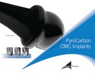
Complementary Product:<br />
Ascension Orthopedics, Inc.<br />
8700 Cameron Road<br />
Austin, Texas 78754<br />
Ascension ® PIP<br />
PyroCarbon Total Joint<br />
512.836.5001 Ph<br />
877.370.5001 TFP<br />
512.836.6933 Fax<br />
888.508.8081 TFF<br />
customerservice@ascensionortho.com<br />
www.ascensionortho.com<br />
Caution: U.S. federal law restricts this device to<br />
sale by or on the order of a physician.<br />
LC-04-527-001 rev C<br />
©2009<br />
At Ascension Orthopedics, we are dedicated<br />
to transforming the <strong>surgical</strong> experience.