CUB5P Data Sheet/Manual PDF - Ritec
CUB5P Data Sheet/Manual PDF - Ritec
CUB5P Data Sheet/Manual PDF - Ritec

Create successful ePaper yourself
Turn your PDF publications into a flip-book with our unique Google optimized e-Paper software.
Bulletin No. <strong>CUB5P</strong>-C<br />
Drawing No. LP0655<br />
Released 7/08<br />
Tel +1 (717) 767-6511<br />
Fax +1 (717) 764-0839<br />
www.redlion.net<br />
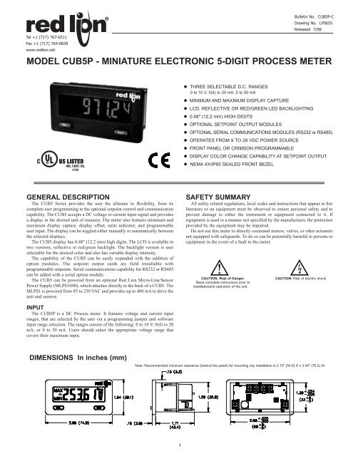
MODEL <strong>CUB5P</strong> - MINIATURE ELECTRONIC 5-DIGIT PROCESS METER<br />
• THREE SELECTABLE D.C. RANGES<br />
0 to 10 V, 0(4) to 20 mA, 0 to 50 mA<br />
• MINIMUM AND MAXIMUM DISPLAY CAPTURE<br />
• LCD, REFLECTIVE OR RED/GREEN LED BACKLIGHTING<br />
• 0.48" (12.2 mm) HIGH DIGITS<br />
• OPTIONAL SETPOINT OUTPUT MODULES<br />
• OPTIONAL SERIAL COMMUNICATIONS MODULES (RS232 or RS485)<br />
• OPERATES FROM 9 TO 28 VDC POWER SOURCE<br />
• FRONT PANEL OR CRIMSON PROGRAMMABLE<br />
• DISPLAY COLOR CHANGE CAPABILITY AT SETPOINT OUTPUT<br />
• NEMA 4X/IP65 SEALED FRONT BEZEL<br />
C<br />
UR<br />
L<br />
US LISTED<br />
IND. CONT. EQ.<br />
51EB<br />
GENERAL DESCRIPTION<br />
The CUB5 Series provides the user the ultimate in flexibility, from its<br />
complete user programming to the optional setpoint control and communication<br />
capability. The CUB5 accepts a DC voltage or current input signal and provides<br />
a display in the desired unit of measure. The meter also features minimum and<br />
maximum display capture, display offset, units indicator, and programmable<br />
user input. The display can be toggled either manually or automatically between<br />
the selected displays.<br />
The CUB5 display has 0.48" (12.2 mm) high digits. The LCD is available in<br />
two versions, reflective or red/green backlight. The backlight version is user<br />
selectable for the desired color and also has variable display intensity.<br />
The capability of the CUB5 can be easily expanded with the addition of<br />
option modules. The setpoint output cards are field installable with<br />
programmable setpoints. Serial communications capability for RS232 or RS485<br />
can be added with a serial option module.<br />
The CUB5 can be powered from an optional Red Lion Micro-Line/Sensor<br />
Power Supply (MLPS1000), which attaches directly to the back of a CUB5. The<br />
MLPS1 is powered from 85 to 250 VAC and provides up to 400 mA to drive the<br />
unit and sensors.<br />
SAFETY SUMMARY<br />
All safety related regulations, local codes and instructions that appear in this<br />
literature or on equipment must be observed to ensure personal safety and to<br />
prevent damage to either the instrument or equipment connected to it. If<br />
equipment is used in a manner not specified by the manufacturer, the protection<br />
provided by the equipment may be impaired.<br />
Do not use this meter to directly command motors, valves, or other actuators<br />
not equipped with safeguards. To do so can be potentially harmful to persons or<br />
equipment in the event of a fault to the meter.<br />
CAUTION: Risk of Danger.<br />
Read complete instructions prior to<br />
installationand operation of the unit.<br />
CAUTION: Risk of electric shock.<br />
INPUT<br />
The <strong>CUB5P</strong> is a DC Process meter. It features voltage and current input<br />
ranges, that are selected by the user via a programming jumper and software<br />
input range selection. The ranges consist of the following: 0 to 10 V, 0(4) to 20<br />
mA, or 0 to 50 mA. Users should select the appropriate voltage range that<br />
covers their maximum input.<br />
DIMENSIONS In inches (mm)<br />
Note: Recommended minimum clearance (behind the panel) for mounting clip installation is 2.15" (54.6) H x 3.00" (76.2) W.<br />
1
ORDERING INFORMATION<br />
GENERAL METER SPECIFICATIONS<br />
1. DISPLAY: 5 digit LCD 0.48" (12.2 mm) high digits<br />
<strong>CUB5P</strong>R00: Reflective LCD with full viewing angle<br />
<strong>CUB5P</strong>B00: Transmissive LCD with selectable red or green LED backlight,<br />
viewing angle optimized. Display color change capability with output state<br />
when using an output module.<br />
2. POWER: Input voltage range is +9 to +28 VDC with short circuit and input<br />
polarity protection. Must use an RLC model MLPS1 or a Class 2 or SELV<br />
rated power supply.<br />
MODEL<br />
NO.<br />
3. INPUT RANGES: Jumper Selectable<br />
0 to 10 V, 0(4) to 20 mA, 0 to 50 mA<br />
4. SENSOR INPUTS:<br />
TYPE MODEL NO. DESCRIPTION PART NUMBER<br />
CUB5<br />
Optional Plug-in Cards<br />
Accessories<br />
DISPLAY COLOR<br />
<strong>CUB5P</strong><br />
CUB5RLY<br />
CUB5SNK<br />
CUB5COM<br />
MLPS1<br />
CBLPROG<br />
CBPRO<br />
SFCRD<br />
Process Meter with reflective display<br />
Process Meter with backlight display<br />
Single Relay Output Card<br />
Dual Sinking Open Collector Output card<br />
RS485 Serial Communications Card<br />
RS232 Serial Communications Card<br />
Micro-Line Power Supply, 85 to 250 VAC<br />
RS232 Programming Cable (DB9-RJ11)<br />
RS485 Programming Cable (DB9-RJ11)<br />
20 / 50 mA 0.1% of span 10 Ω 150 mA 1 µA 70 ppm / °C<br />
10 VDC 0.1% of span 538 KΩ 30 V 1 mV 70 ppm / °C<br />
5. OVERRANGE RATINGS, PROTECTION & INDICATION:<br />
9 to 28 VDC power circuit is not isolated from the signal circuit.<br />
Input Overrange Indication: “OLOL”.<br />
Input Underrange Indication: “ULUL”.<br />
Display Overrange/Underrange Indication: “.....”/“-.....”<br />
6. DISPLAY RESPONSE TIME: 500 msec min.<br />
7. NORMAL MODE REJECTION: 60 dB 50/60 Hz<br />
8. USER INPUT (USR): Programmable input. Connect USR terminal to USR<br />
COMM to activate function. Internal 10KΩ pull-up resistor to +9 to 28 VDC.<br />
Threshold Levels: V IL = 1.0 V max; V IH = 2.4 V min; V MAX = 28 VDC<br />
Response Time: 5 msec typ.; 50 msec debounce (activation and release)<br />
9. CONNECTIONS: Wire clamping screw terminals<br />
Wire Strip Length: 0.3" (7.5 mm)<br />
Wire Gage: 30-14 AWG copper wire<br />
Torque: 5 inch-lbs (0.565 N-m) max.<br />
10. MEMORY: Nonvolatile E 2 PROM memory retains all programming<br />
parameters and max/min values when power is removed.<br />
11. CONSTRUCTION: This unit is rated for NEMA 4X/IP65 requirements for<br />
indoor use. Installation Category I, Pollution Degree 2. High impact plastic<br />
case with clear viewing window. Panel gasket and mounting clip included.<br />
12. ENVIRONMENTAL CONDITIONS:<br />
Operating Temperature Range for <strong>CUB5P</strong>R00: -35 to 75°C<br />
Operating Temperature Range for <strong>CUB5P</strong>B00 depends on display color<br />
and intensity level as per below:<br />
Crimson 2 PC Configuration Software for Windows 98, ME, 2000, XP *<br />
INPUT CURRENT<br />
@ 9 VDC WITH<br />
CUB5RLY0<br />
<strong>CUB5P</strong>R00 --- 10 mA 40 mA<br />
<strong>CUB5P</strong>B00 Red (max intensity) 85 mA 115 mA<br />
<strong>CUB5P</strong>B00 Green (max intensity) 95 mA 125 mA<br />
INPUT<br />
RANGE<br />
Green Display<br />
*Crimson 2 software is a free download from http://www.redlion.net/<br />
ACCURACY<br />
@23 °C, less<br />
than 85% RH<br />
Red Display<br />
INPUT CURRENT<br />
@ 9 VDC WITHOUT<br />
CUB5RLY0<br />
INPUT MAX INPUT<br />
IMPEDANCE SIGNAL<br />
RESOLUTION<br />
INTENSITY LEVEL TEMPERATURE<br />
1 & 2 -35 to 75°C<br />
3 -35 to 70°C<br />
4 -35 to 60°C<br />
5 -35 to 50°C<br />
1 & 2 -35 to 75°C<br />
3 -35 to 65°C<br />
4<br />
-35 to 50°C<br />
5<br />
-35 to 35°C<br />
TEMP.<br />
COEFFICIENT<br />
2<br />
<strong>CUB5P</strong>R00<br />
<strong>CUB5P</strong>B00<br />
CUB5RLY0<br />
CUB5SNK0<br />
CUB5COM1<br />
CUB5COM2<br />
MLPS1000<br />
CBLPROG0<br />
CBPRO007<br />
SFCRD200<br />
Storage Temperature: -35 to 85°C<br />
Operating and Storage Humidity: 0 to 85% max. relative humidity (noncondensing)<br />
Vibration According to IEC 68-2-6: Operational 5 to 500 Hz, in X, Y, Z<br />
direction for 1.5 hours, 5 g’s.<br />
Shock According to IEC 68-2-27: Operational 30 g, 11 msec in 3 directions.<br />
Altitude: Up to 2000 meters<br />
13. CERTIFICATIONS AND COMPLIANCES:<br />
SAFETY<br />
UL Recognized Component, File #E179259, UL61010A-1, CSA 22.2 No. 61010-1<br />
Recognized to U.S. and Canadian requirements under the Component<br />
Recognition Program of Underwriters Laboratories, Inc.<br />
UL Listed, File # E137808, UL508, CSA C22.2 No. 14-M95<br />
LISTED by Und. Lab. Inc. to U.S. and Canadian safety standards<br />
Type 4X Indoor Enclosure rating (Face only), UL50<br />
IECEE CB Scheme Test Certificate #US/9257C/UL<br />
CB Scheme Test Report #E179259-V01-S02<br />
Issued by Underwriters Laboratories, Inc.<br />
IEC 61010-1, EN 61010-1: Safety requirements for electrical equipment<br />
for measurement, control, and laboratory use, Part 1.<br />
IP65 Enclosure rating (Face only), IEC 529<br />
ELECTROMAGNETIC COMPATIBILITY<br />
Emissions and Immunity to EN 61326: Electrical Equipment for<br />
Measurement, Control and Laboratory use.<br />
Immunity to Industrial Locations:<br />
Electrostatic discharge EN 61000-4-2 Criterion A<br />
4 kV contact discharge<br />
8 kV air discharge<br />
Electromagnetic RF fields EN 61000-4-3 Criterion A<br />
10 V/m<br />
Fast transients (burst) EN 61000-4-4 Criterion A<br />
2 kV power<br />
1 kV signal<br />
Surge<br />
EN 61000-4-5 Criterion A<br />
1 kV L-L,<br />
2 kV L&N-E power<br />
RF conducted interference EN 61000-4-6 Criterion A<br />
3 V/rms<br />
Power frequency magnetic fields EN 61000-4-8 Criterion A<br />
30 A/m<br />
Emissions:<br />
Emissions<br />
EN 55011<br />
Class A<br />
Notes:<br />
1. Criterion A: Normal operation within specified limits.<br />
Refer to EMC Installation Guidelines for additional information.<br />
14. WEIGHT: 3.2 oz (100 g)
OPTIONAL PLUG-IN CARDS<br />
ADDING OPTION CARDS<br />
The CUB5 meters can be fitted with optional output cards and/or serial<br />
communications cards. The details for the plug-in cards can be reviewed in the<br />
specification section below. The plug-in cards, that are sold separately, can be<br />
installed initially or at a later date.<br />
WARNING: Disconnect all power to the unit before<br />
installing Plug-in card.<br />
Note: Measurement errors may occur if signal input common is shared with<br />
another circuit common (ie, serial common, Dual Sinking Output option card,<br />
or Power Supply common) on multiple units.<br />
SINGLE RELAY CARD<br />
Type: Single FORM-C relay<br />
Isolation To Sensor & User Input Commons: 1400 Vrms for 1 min.<br />
Working Voltage: 150 Vrms<br />
Contact Rating: 1 amp @ 30 VDC resistive; 0.3 amp @ 125 VAC resistive<br />
Life Expectancy: 100,000 minimum operations<br />
Response Time:<br />
Turn On Time: 4 msec max.<br />
Turn Off Time: 4 msec max.<br />
DUAL SINKING OUTPUT CARD<br />
Type: Non-isolated switched DC, N Channel open drain MOSFET<br />
Current Rating: 100 mA max.<br />
V DS ON : 0.7 V @ 100 mA<br />
V DS MAX : 30 VDC<br />
Offstate Leakage Current: 0.5 mA max.<br />
RS485 SERIAL COMMUNICATIONS CARD<br />
Type: RS485 multi-point balanced interface (non-isolated)<br />
Baud Rate: 300 to 38.4k<br />
<strong>Data</strong> Format: 7/8 bits; odd, even, or no parity<br />
Bus Address: 0 to 99; max 32 meters per line<br />
Transmit Delay: Selectable (refer to CUB5COM bulletin)<br />
RS232 SERIAL COMMUNICATIONS CARD<br />
Type: RS232 half duplex (non-isolated)<br />
Baud Rate: 300 to 38.4k<br />
<strong>Data</strong> Format: 7/8 bits; odd, even, or no parity<br />
1.0 INSTALLING THE METER<br />
INSTALLATION<br />
The meter meets NEMA 4X/IP65 requirements when properly installed. The<br />
unit is intended to be mounted into an enclosed panel. Prepare the panel cutout<br />
to the dimensions shown. Remove the panel latch from<br />
the unit. Slide the panel gasket over the rear of the<br />
unit to the back of the bezel. The unit should be<br />
installed fully assembled. Insert the unit into<br />
the panel cutout.<br />
While holding the unit in place, push the panel latch over the rear of the unit<br />
so that the tabs of the panel latch engage in the slots on the case. The panel latch<br />
should be engaged in the farthest forward slot possible. To achieve a proper seal,<br />
tighten the latch screws evenly until the unit is snug in the panel (Torque to<br />
approx. 28 to 36 in-oz [0.202 to 0.26 N-m]). Do not over-tighten the screws.<br />
INSTALLATION ENVIRONMENT<br />
The unit should be installed in a location that does not exceed the operating<br />
temperature and provides good air circulation. Placing the unit near devices that<br />
generate excessive heat should be avoided.<br />
The bezel should only be cleaned with a soft cloth and neutral soap product.<br />
Do NOT use solvents. Continuous exposure to direct sunlight may accelerate the<br />
aging process of the bezel.<br />
Do not use tools of any kind (screwdrivers, pens, pencils, etc.) to operate the<br />
keypad of the unit.<br />
2.0 SETTING THE JUMPERS<br />
INPUT RANGE JUMPER<br />
This jumper is used to select the proper input range. The input range selected<br />
in programming must match the jumper setting. Select a range that is high<br />
enough to accommodate the maximum input signal to avoid overloads. To<br />
access the jumper, remove the rear cover of the meter.<br />
Warning: Exposed line voltage exists on the circuit boards.<br />
Remove all power to the meter and load circuits before accessing<br />
inside of the meter.<br />
REMOVING THE REAR COVER<br />
To remove the rear cover, locate the cover locking tab below the 2nd and 3rd<br />
input terminals. To release the tab, insert a small, flat blade screwdriver between<br />
the tab and the plastic wall below the terminals. Inserting the screwdriver will<br />
provide enough pressure to release the tab locks. To replace the cover, align the<br />
cover with the input terminals and press down until the cover snaps into place.<br />
3
3.0 INSTALLING PLUG-IN CARDS<br />
The Plug-in cards are separately purchased option cards that perform specific<br />
functions. The cards plug into the main circuit board of the meter<br />
Comms Card<br />
Range Jumpers<br />
Setpoint Card<br />
CAUTION: The Plug-in cards and main circuit board contain static<br />
sensitive components. Before handling the cards, discharge<br />
static charges from your body by touching a grounded bare<br />
metal object. Ideally, handle the cards at a static controlled<br />
clean workstation. Also, only handle the cards by the edges.<br />
Dirt, oil or other contaminants that may contact the cards can<br />
adversely affect circuit operation.<br />
REMOVING THE REAR COVER<br />
To remove the rear cover, locate the cover locking tab below the 2nd and 3rd<br />
input terminals. To release the tab, insert a small, flat blade screwdriver between<br />
the tab and the plastic wall below the terminals. Inserting the screwdriver will<br />
provide enough pressure to release the tab locks. To replace the cover, align the<br />
cover with the input terminals and press down until the cover snaps into place.<br />
Locking Tab<br />
4.0 WIRING THE METER<br />
WIRING OVERVIEW<br />
Electrical connections are made via screw-clamp terminals located on the<br />
back of the meter. All conductors should conform to the meter’s voltage and<br />
current ratings. All cabling should conform to appropriate standards of good<br />
installation, local codes and regulations. It is recommended that the power<br />
supplied to the meter (DC or AC) be protected by a fuse or circuit breaker.<br />
Strip the wire, leaving approximately 0.3" (7.5 mm) bare lead exposed<br />
(stranded wires should be tinned with solder.) Insert the lead under the correct<br />
screw-clamp terminal and tighten until the wire is secure. (Pull wire to verify<br />
tightness.) Each terminal can accept up to one #14 AWG (2.55 mm) wire, two<br />
#18 AWG (1.02 mm), or four #20 AWG (0.61 mm).<br />
EMC INSTALLATION GUIDELINES<br />
Although this meter is designed with a high degree of immunity to Electro-<br />
Magnetic Interference (EMI), proper installation and wiring methods must be<br />
followed to ensure compatibility in each application. The type of the electrical<br />
noise, source or coupling method into the meter may be different for various<br />
installations. The meter becomes more immune to EMI with fewer I/O<br />
connections. Cable length, routing, and shield termination are very important<br />
and can mean the difference between a successful or troublesome installation.<br />
Listed below are some EMC guidelines for successful installation in an<br />
industrial environment.<br />
1. The meter should be mounted in a metal enclosure, which is properly<br />
connected to protective earth.<br />
2. Use shielded (screened) cables for all Signal and Control inputs. The shield<br />
(screen) pigtail connection should be made as short as possible. The<br />
connection point for the shield depends somewhat upon the application.<br />
Listed below are the recommended methods of connecting the shield, in order<br />
of their effectiveness.<br />
a. Connect the shield only at the panel where the unit is mounted to earth<br />
ground (protective earth).<br />
b. Connect the shield to earth ground at both ends of the cable, usually when<br />
the noise source frequency is above 1 MHz.<br />
4.1 POWER WIRING<br />
DC Power<br />
+9 to +28 VDC: +VDC<br />
Power Common: -VDC<br />
CAUTION: 9 to 28 VDC<br />
power circuit is not isolated<br />
from the signal circuit.<br />
c. Connect the shield to common of the meter and leave the other end of the<br />
shield unconnected and insulated from earth ground.<br />
3. Never run Signal or Control cables in the same conduit or raceway with AC<br />
power lines, conductors feeding motors, solenoids, SCR controls, and<br />
heaters, etc. The cables should be ran in metal conduit that is properly<br />
grounded. This is especially useful in applications where cable runs are long<br />
and portable two-way radios are used in close proximity or if the installation<br />
is near a commercial radio transmitter.<br />
4. Signal or Control cables within an enclosure should be routed as far as possible<br />
from contactors, control relays, transformers, and other noisy components.<br />
5. In extremely high EMI environments, the use of external EMI suppression<br />
devices, such as ferrite suppression cores, is effective. Install them on Signal<br />
and Control cables as close to the unit as possible. Loop the cable through the<br />
core several times or use multiple cores on each cable for additional protection.<br />
Install line filters on the power input cable to the unit to suppress power line<br />
interference. Install them near the power entry point of the enclosure. The<br />
following EMI suppression devices (or equivalent) are recommended:<br />
Ferrite Suppression Cores for signal and control cables:<br />
Fair-Rite # 0443167251 (RLC# FCOR0000)<br />
TDK # ZCAT3035-1330A<br />
Steward # 28B2029-0A0<br />
Line Filters for input power cables:<br />
Schaffner # FN610-1/07 (RLC# LFIL0000)<br />
Schaffner # FN670-1.8/07<br />
Corcom # 1 VR3<br />
Note: Reference manufacturer’s instructions when installing a line filter.<br />
6. Long cable runs are more susceptible to EMI pickup than short cable runs.<br />
Therefore, keep cable runs as short as possible.<br />
7. Switching of inductive loads produces high EMI. Use of snubbers across<br />
inductive loads suppresses EMI.<br />
Snubber: RLC# SNUB0000.<br />
4.2 USER INPUT WIRING<br />
Sinking Logic<br />
USR COMM Connect external switching device between the<br />
USR }User Input terminal and User Input Common.<br />
The user input of the meter is<br />
internally pulled up to +9 to +28 V<br />
with 10 K resistance. The input is<br />
active when it is pulled low (
4.3 INPUT WIRING<br />
CAUTION: Power input common is NOT isolated from user and input<br />
commons. In order to preserve the safety of the meter application, the<br />
power input common must be suitably isolated from hazardous live<br />
earth referenced voltage; or input common must be at protective earth<br />
ground potential. If not, hazardous voltage may be present at the signal or user<br />
inputs and input common terminals. Appropriate considerations must then be given<br />
to the potential of the user and input commons with respect to earth ground; and the<br />
common of the plug-in cards with respect to input common.<br />
Before connecting signal wires, the Input Range Jumper should be verified for<br />
proper position.<br />
Input Signal (self powered)<br />
2 Wire With External Power<br />
2 Wire With MLPS Power<br />
JUMPER<br />
POSITION<br />
10 VDC<br />
20/50 mA DC<br />
MAX SIGNAL<br />
INPUT<br />
30 VDC<br />
150 mA<br />
Series Loop (must use separate supply for sensor power<br />
and each CUB5)<br />
2 Wire With Separate Sensor And CUB5 Power<br />
4.4 SETPOINT (OUTPUT) WIRING<br />
SINGLE SETPOINT RELAY PLUG-IN CARD<br />
ELECTRICAL CONNECTIONS<br />
DUAL SETPOINT N-FET OPEN DRAIN PLUG-IN CARD<br />
ELECTRICAL CONNECTIONS<br />
Output Common is not isolated from DC Power Common. Load<br />
must be wired between OSNK terminal and V+ of the load supply.<br />
4.5 SERIAL COMMUNICATION WIRING<br />
SERIAL COMMUNICATIONS PLUG-IN CARD<br />
RJ11 CONNECTOR PIN OUTS<br />
5
5.0 REVIEWING THE FRONT BUTTONS AND DISPLAY<br />
BUTTON DISPLAY MODE OPERATION ENTERING PROGRAM MODE PROGRAMMING MODE OPERATION<br />
SEL Index display through enabled values Press and hold for 2 seconds to activate Store selected parameter and index to next parameter<br />
RST<br />
Resets values (MIN/MAX) or outputs<br />
Advances through the program menu<br />
Increments selected parameter value or selection<br />
OPERATING MODE DISPLAY DESIGNATORS<br />
MAX - Maximum display capture value<br />
MIN - Minimum display capture value<br />
“1” - To the right of the display indicates setpoint 1 output activated.<br />
“2” - To the right of the display indicates setpoint 2 output activated.<br />
Pressing the SEL button toggles the meter through the selected displays. If display scroll is enabled, the display will toggle automatically every four seconds between<br />
the enabled display values.<br />
6.0 PROGRAMMING THE METER<br />
OVERVIEW<br />
PROGRAMMING MENU<br />
PROGRAMMING MODE ENTRY (SEL BUTTON)<br />
It is recommended all programming changes be made off line, or before<br />
installation. The meter normally operates in the Display Mode. No parameters<br />
can be programmed in this mode. The Programming Mode is entered by<br />
pressing and holding the SEL button. If it is not accessible then it is locked by<br />
either a security code, or a hardware lock.<br />
MODULE ENTRY (SEL & RST BUTTONS)<br />
The Programming Menu is organized into separate modules. These modules<br />
group together parameters that are related in function. The display will alternate<br />
between Pro and the present module. The RST button is used to select the desired<br />
module. The displayed module is entered by pressing the SEL button.<br />
MODULE MENU (SEL BUTTON)<br />
Each module has a separate module menu (which is shown at the start of each<br />
module discussion). The SEL button is pressed to advance to a particular<br />
parameter to be changed, without changing the programming of preceding<br />
parameters. After completing a module, the display will return to Pro NO.<br />
Programming may continue by accessing additional modules.<br />
SELECTION / VALUE ENTRY<br />
For each parameter, the display alternates between the present parameter and<br />
the selections/value for that parameter. The RST button is used to move through<br />
the selections/values for that parameter. Pressing the SEL button, stores and<br />
activates the displayed selection/value. This also advances the meter to the next<br />
parameter.<br />
For numeric values, press the RST button to access the value. The right hand<br />
most digit will begin to flash. Pressing the RST button again increments the<br />
digit by one or the user can hold the RST button and the digit will automatically<br />
scroll. The SEL button will advance to the next digit. Pressing and holding the<br />
SEL button will enter the value and move to the next parameter.<br />
PROGRAMMING MODE EXIT (SEL BUTTON)<br />
The Programming Mode is exited by pressing the SEL button with Pro NO<br />
displayed. This will commit any stored parameter changes to memory and<br />
return the meter to the Display Mode. (If power loss occurs before returning to<br />
the Display Mode, verify recent parameter changes.)<br />
PROGRAMMING TIPS<br />
It is recommended to start with Module 1 and proceed through each module in<br />
sequence. When programming is complete, it is recommended to record the<br />
parameter programming and lock out parameter programming with the user input<br />
or programming security code.<br />
FACTORY SETTINGS<br />
Factory Settings may be completely restored in Module 2. This is useful<br />
when encountering programming problems.<br />
ALTERNATING SELECTION DISPLAY<br />
In the explanation of the modules, the following dual display with arrows will<br />
appear. This is used to illustrate the display alternating between the parameter<br />
on top and the parameter’s Factory Setting on the bottom. In most cases,<br />
selections and values for the parameter will be listed on the right.<br />
Indicates Program Mode Alternating Display<br />
Parameter<br />
USrIN<br />
<br />
<br />
N0<br />
Factory Settings are shown.<br />
Selection/Value<br />
6
6.1 MODULE 1 - SIGNAL INPUT PARAMETERS (1-INP)<br />
PARAMETER MENU<br />
rAN6E<br />
<br />
<br />
10u<br />
<strong>CUB5P</strong> INPUT RANGE<br />
Select the input range that corresponds to the external signal. This selection<br />
should be high enough to avoid input signal overload but low enough for the<br />
desired input resolution. This selection and the position of the Input Range<br />
Jumper must match.<br />
dECPt 0 0.0 0.00 0.000 0.0000<br />
<br />
0.000<br />
DISPLAY DECIMAL POINT<br />
Select the decimal point location for the Input, MIN and MAX displays. This<br />
selection also affects the dSP1 and dSP2 parameters and setpoint values.<br />
OFSEt <br />
0.000<br />
FILtr<br />
<br />
<br />
1<br />
FILTER SETTING<br />
0,1 2 3<br />
If the displayed value is difficult to read due to small process variations or<br />
noise, increased levels of filtering will help to stabilize the display. Software<br />
filtering effectively combines a fraction of the current input reading with a<br />
fraction of the previous displayed reading to generate the new display.<br />
Filter values represent no filtering (0), up to heavy filtering (3). A value of 1<br />
for the filter uses 1/4 of the new input and 3/4 of the previous display to generate<br />
the new display. A filter value of 2 uses 1/8 new and 7/8 previous. A filter value<br />
of 3 uses 1/16 new and 15/16 previous.<br />
bANd<br />
<br />
<br />
10<br />
SELECTION<br />
10u<br />
RANGE<br />
RESOLUTION<br />
10.000 V<br />
DISPLAY OFFSET VALUE<br />
-19999 to 19999<br />
FILTER BAND<br />
0 to 199 display units<br />
SELECTION<br />
RANGE<br />
RESOLUTION<br />
0.02A 20.000 mA<br />
50.000 mA<br />
0.05A<br />
The display can be corrected with an offset value. This can be used to<br />
compensate for signal variations or sensor errors. This value is automatically<br />
updated after a Zero Display to show how far the display is offset. A value of<br />
zero will remove the effects of offset.<br />
The filter will adapt to variations in the input signal. When the variation<br />
exceeds the input filter band value, the filter disengages. When the variation<br />
becomes less than the band value, the filter engages again. This allows for a<br />
stable readout, but permits the display to settle rapidly after a large process<br />
change. The value of the band is in display units, independent of the Display<br />
Decimal Point position. A band setting of ‘0’ keeps the filter permanently<br />
engaged at the filter level selected above.<br />
StYLE<br />
<br />
<br />
KEy<br />
KEy<br />
SCALING STYLE<br />
APLY<br />
If Input Values and corresponding Display Values are known, the Key-in<br />
(KEY) scaling style can be used. This allows scaling without the presence or<br />
changing of the input signal. If Input Values have to be derived from the actual<br />
input signal source or simulator, the Apply (APLY) scaling style must be used.<br />
INP 1 <br />
0.000<br />
INPUT VALUE FOR SCALING POINT 1<br />
0 to 59999<br />
For Key-in (KEY) style, enter the known first Input Value using the front panel<br />
buttons. (The Input Range selection sets the decimal location for the Input<br />
Value).<br />
For Apply (APLY) style, the meter shows the previously stored Input Value. To<br />
retain this value, press the SEL button to advance to the next parameter. To<br />
change the Input Value, press the RST button and apply the input signal to the<br />
meter. Adjust the signal source externally until the desired Input Value appears.<br />
Press the SEL button to enter the value being displayed.<br />
dSP 1 <br />
0.000<br />
DISPLAY VALUE FOR SCALING POINT 1<br />
-19999 to 99999<br />
Enter the first Display Value using the front panel buttons. This is the same<br />
for KEY and APLY scaling styles. The decimal point follows the dECPt selection.<br />
INP 2 <br />
10.000<br />
INPUT VALUE FOR SCALING POINT 2<br />
0 to 59999<br />
For Key-in (KEY) style, enter the known second Input Value using the front<br />
panel buttons.<br />
For Apply (APLY) style, the meter shows the previously stored Input Value for<br />
Scaling Point 2. To retain this value, press the SEL button to advance to the next<br />
parameter. To change the Input Value, press the RST button and apply the input<br />
signal to the meter. Adjust the signal source externally until the desired Input<br />
Value appears. Press the SEL button to enter the value being displayed.<br />
dSP 2 <br />
10.000<br />
DISPLAY VALUE FOR SCALING POINT 2<br />
-19999 to 99999<br />
Enter the second Display Value using the front panel buttons. This is the same<br />
for KEY and APLY scaling styles.<br />
General Notes on Scaling<br />
1. When using the Apply (APLY) scaling style, input values for scaling points<br />
must be confined to signal limits of the selected range.<br />
2. The same Input Value should not correspond to more than one Display Value.<br />
(Example: 10 V can not equal 0 and 10.)<br />
3. For input levels beyond the programmed Input Values, the meter extends the<br />
Display Value by calculating the slope from the two coordinate pairs (INP1 /<br />
dSP1 & INP2 / dSP2).<br />
7
USrIN<br />
<br />
DISPLAY MODE<br />
No Function<br />
NO<br />
P-Loc<br />
Program Mode Lock-out<br />
Zero Input<br />
ZErO (Edge triggered)<br />
rESEt<br />
d-HLd<br />
d-SEL<br />
d-LEV<br />
COLOr<br />
<br />
NO<br />
Reset (Edge triggered)<br />
Display Hold<br />
Display Select<br />
(Edge Triggered)<br />
Display Intensity Level<br />
(Edge Triggered)<br />
Backlight Color<br />
(Edge Triggered)<br />
USER INPUT FUNCTION<br />
DESCRIPTION<br />
User Input disabled.<br />
See Programming Mode Access chart<br />
(Module 3).<br />
Zero the Input Display value causing<br />
Display Reading to be Offset.<br />
Resets the assigned value(s) to the<br />
current input value.<br />
Holds the assigned display, but all other<br />
meter functions continue as long as<br />
activated (maintained action).<br />
Advance once for each activation.<br />
Increase intensity one level for each<br />
activation (backlight version only).<br />
Change backlight color with each<br />
activation (backlight version only).<br />
DISPLAY MODE<br />
Print<br />
P-r5t<br />
rSt-1<br />
rSt-2<br />
rSt12<br />
U-ASN<br />
<br />
Print Request<br />
Print and Reset<br />
Setpoint 1 Reset<br />
Setpoint 2 Reset<br />
Setpoint 1 and 2 Reset<br />
<br />
dSP<br />
USER INPUT ASSIGNMENT<br />
HI<br />
LO<br />
DESCRIPTION<br />
Serial transmit of the active parameters<br />
selected in the Print Options menu<br />
(Module 5).<br />
Same as Print Request followed by a<br />
momentary reset of the assigned value(s).<br />
Resets setpoint 1 output.<br />
Resets setpoint 2 output.<br />
Reset both setpoint 1 and 2 outputs.<br />
HI-LO<br />
dSP<br />
Select the value(s) to which the User Input Function is assigned. The User<br />
Input Assignment only applies if a selection of reset, display hold, or print and<br />
reset is selected in the User Input Function menu.<br />
6.2 MODULE 2 - SECONDARY FUNCTION PARAMETERS (2-SEC)<br />
PARAMETER MENU<br />
HI-En<br />
<br />
HI-t<br />
<br />
LO-En<br />
<br />
FCS<br />
<br />
<br />
2.0<br />
<br />
NO<br />
<br />
NO<br />
MAX CAPTURE DELAY TIME<br />
When the Input Display is above the present MAX value for the entered<br />
delay time, the meter will capture that display value as the new MAX reading.<br />
A delay time helps to avoid false captures of sudden short spikes.<br />
LO-t<br />
<br />
<br />
NO<br />
<br />
2.0<br />
MAX DISPLAY ENABLE<br />
NO<br />
0.0 to 999.9 sec.<br />
MIN DISPLAY ENABLE<br />
NO<br />
YES<br />
MIN CAPTURE DELAY TIME<br />
0.0 to 999.9 sec.<br />
When the Input Display is below the present MIN value for the entered delay<br />
time, the meter will capture that display value as the new MIN reading. A delay<br />
time helps to avoid false captures of sudden short spikes.<br />
FACTORY SERVICE OPERATIONS<br />
NO<br />
YES<br />
Enables the Maximum Display Capture capability.<br />
Enables the Minimum Display Capture capability.<br />
yES<br />
Select yES to perform either of the Factory Service Operations shown below.<br />
8<br />
CodE<br />
<br />
CodE<br />
<br />
CodE<br />
RESTORE FACTORY DEFAULT SETTINGS<br />
<br />
66<br />
<br />
50<br />
<br />
48<br />
Entering Code 66 will overwrite all user settings with<br />
the factory settings. The meter will display rESEt and then<br />
return to CodE 00. Press the SEL button to exit the module.<br />
VIEW VERSION DISPLAY<br />
Entering Code 50 will display the version (x.x) of the<br />
meter. The display then returns to CodE 00. Press the SEL<br />
button to exit the module.<br />
CALIBRATION<br />
The <strong>CUB5P</strong> uses stored calibration values to provide<br />
accurate voltage and current measurements. Over time,<br />
<br />
the electrical characteristics of the components inside the<br />
meter could slowly change, therefore the stored<br />
calibration values may no longer accurately define the input circuit. For most<br />
applications, recalibration every 1 to 2 years should be sufficient.<br />
Calibration of the <strong>CUB5P</strong> involves a voltage or current calibration, which<br />
should only be performed by individuals experienced in calibrating electronic<br />
equipment. Allow a 30 minute warm up for eqiupment and unit before<br />
performing any calibration related procedures. The following procedures should<br />
be performed at an ambient temperature of 15 to 35°C (59 to 95°F).<br />
CAUTION: The accuracy of the calibration equipment will directly affect the<br />
accuracy of the <strong>CUB5P</strong>.<br />
Calibration<br />
1. Connect the negative lead of a precision DC source with an accuracy of 0.01%<br />
or better to the COMM. Leave the positive lead of the DC source unconnected.<br />
2. With the display at CodE 48, press and hold the SEL button for 2 seconds. Unit<br />
will display CAL NO.<br />
3. Press the RST button to select the range to be calibrated.<br />
4. Press the SEL button. Display reads 0.0A (0.0 V for voltage).<br />
5. Apply 0 signal:<br />
Current: leave the positive lead of the DC source unconnected.<br />
Voltage: apply a short to the input or connect the positive lead of the DC<br />
source to INP+ and set the source to 0.<br />
Press SEL. Display reads CALC for about 8 seconds.<br />
6. When the display reads the selected range (10 V, 20 mA, or 50 mA), connect<br />
the positive lead of the DC source to INP+ and apply the full scale input signal<br />
for the range. Press SEL. Display reads CALC for about 8 seconds.<br />
7. Repeat steps 3 through 6 for each input range to be calibrated. When display<br />
reads CAL NO, press the SEL button to exit calibration.
6.3 MODULE 3 - DISPLAY AND FRONT PANEL BUTTON<br />
PARAMETERS (3-dSP)<br />
PARAMETER MENU<br />
dSP-t<br />
<br />
SEL<br />
<br />
The yES selection allows the SEL button to toggle through the enabled<br />
displays.<br />
rSt<br />
<br />
FRONT PANEL DISPLAY SELECT ENABLE (SEL)<br />
This selection allows the RST button to reset the selected value(s).<br />
ZErO<br />
<br />
<br />
1<br />
<br />
yES<br />
FRONT PANEL RESET ENABLE (RST)<br />
<br />
dSP<br />
yES<br />
NO<br />
HI<br />
NO<br />
LO<br />
HI-LO<br />
dSP<br />
ZERO DISPLAY WITH DISPLAY RESET<br />
<br />
NO<br />
DISPLAY UPDATE TIME<br />
0.5 1 2 seconds<br />
This parameter sets the display update time in seconds.<br />
yES<br />
This parameter enables the RST button or user input to zero the input display<br />
value, causing the display reading to be offset.<br />
Note: For this parameter to operate, the RST button or User Input being used<br />
must be set to dSP and the Input value must be displayed. If these conditions are<br />
not met, the display will not zero.<br />
NO<br />
COLOr<br />
<br />
DISPLAY COLOR (BACKLIGHT UNIT ONLY)<br />
rEd<br />
Enter the desired display color, red or green. This parameter is active for<br />
backlight units only.<br />
PROGRAMMING SECURITY CODE<br />
000 to 999<br />
The Security Code determines the programming mode and the accessibility<br />
of programming parameters. This code can be used along with the Program<br />
Mode Lock-out (P-Loc) in the User Input Function parameter (Module 1).<br />
Two programming modes are available. Full Programming mode allows all<br />
parameters to be viewed and modified. Quick Programming mode permits only<br />
the Setpoint values to be modified, but allows direct access to these values<br />
without having to enter Full Programming mode.<br />
Programming a Security Code other than 0, requires this code to be entered<br />
at the CodE prompt in order to access Full Programming mode. Depending on the<br />
code value, Quick Programming may be accessible before the CodE prompt<br />
appears (see chart).<br />
6rn<br />
DISPLAY INTENSITY LEVEL (BACKLIGHT UNIT ONLY)<br />
d-LEV<br />
<br />
Enter the desired Display Intensity Level (1-5). The display will actively dim<br />
or brighten as levels are changed. This parameter is active for backlight units only.<br />
CodE<br />
<br />
<br />
rEd<br />
<br />
5<br />
<br />
000<br />
1 to 5<br />
ScroL<br />
<br />
DISPLAY SCROLL ENABLE<br />
yES<br />
The yES selection allows the display to automatically scroll through the<br />
enabled displays. The scroll rate is every 4 seconds. This parameter only appears<br />
when the MAX or MIN displays are enabled.<br />
UNItS<br />
<br />
<br />
NO<br />
<br />
OFF<br />
This parameter activates the Units Indicator on the display. There are two<br />
methods of selecting the Indicator. List will present a group of Units<br />
preprogrammed into the meter. Segments allows the user to choose which of the<br />
segments should light.<br />
NO<br />
UNITS INDICATOR SELECTION<br />
OFF<br />
LISt<br />
SEGS<br />
USER INPUT<br />
FUNCTION<br />
not P-Loc<br />
P-Loc<br />
USER INPUT<br />
STATE<br />
______<br />
SECURITY<br />
CODE<br />
MODE WHEN “SEL” FULL PROGRAMMING<br />
BUTTON IS PRESSED MODE ACCESS<br />
0 Full Programming Immediate Access<br />
After Quick Programming<br />
1-99 Quick Programming with correct code entry<br />
at CodE prompt *<br />
100-999 CodE prompt<br />
With correct code entry<br />
at CodE prompt *<br />
0 Programming Lock No Access<br />
Active 1-99 Quick Programming No Access<br />
100-999 CodE prompt<br />
With correct code entry<br />
at CodE prompt *<br />
Not Active 0-999 Full Programming Immediate Access<br />
* Entering Code 222 allows access regardless of security code.<br />
9
6.4 MODULE 4 - SETPOINT OUTPUT PARAMETERS (4-SPt)<br />
PARAMETER MENU<br />
The Setpoint Output Parameters are only active when an optional output<br />
module is installed in the meter.<br />
SPSEL<br />
<br />
<br />
NO<br />
SETPOINT SELECT<br />
NO<br />
SP-1<br />
SP-2<br />
Enter the setpoint (output) to be programmed. The n in the following<br />
parameters will reflect the chosen setpoint number. After the chosen setpoint<br />
is completely programmed, the display will return to SPSEL. Repeat steps for<br />
each setpoint to be programmed. Select NO to exit the module. The number of<br />
setpoints available is setpoint output card dependent.<br />
Enb-2<br />
<br />
<br />
NO<br />
YES<br />
SETPOINT 2 ENABLE<br />
NO<br />
Select YES to enable Setpoint 2 and access the setup parameters. If NO is<br />
selected, the unit returns to SPSEL and setpoint 2 is disabled.<br />
SPt-n <br />
10000<br />
HYS-n<br />
<br />
<br />
2<br />
SETPOINT VALUE<br />
-19999 to 99999<br />
Enter the desired setpoint value. The decimal point position for the setpoint<br />
and hysteresis values follow the selection set in Module 1.<br />
HYSTERESIS VALUE<br />
1 to 59999<br />
Enter desired hysteresis value. See Setpoint Output Figures for visual<br />
explanation of how setpoint output actions (balanced and unbalanced) are<br />
affected by the hysteresis. When the setpoint is a control output, usually<br />
balanced hysteresis is used. For alarm applications, usually unbalanced<br />
hysteresis is used. For unbalanced hysteresis modes, the hysteresis functions on<br />
the low side for high acting setpoints and functions on the high side for low<br />
acting setpoints.<br />
Note: Hysteresis eliminates output chatter at the switch point, while time delay<br />
can be used to prevent false triggering during process transient events.<br />
Act-n <br />
HI-Ub<br />
SETPOINT ACTION<br />
HI-bL<br />
LO-bL<br />
HI-Ub<br />
LO-Ub<br />
Enter the action for the selected setpoint (output). See Setpoint Output<br />
Figures for a visual detail of each action.<br />
tON-n<br />
<br />
<br />
0.0<br />
ON TIME DELAY<br />
0.0 to 599.9 Sec<br />
Enter the time value in seconds that the output is delayed from turning on<br />
after the trigger point is reached. A value of 0.0 allows the meter to update the<br />
output status per the response time listed in the Specifications.<br />
HI-bL =<br />
LO-bL =<br />
HI-Ub =<br />
LO-Ub =<br />
High Acting, with balanced hysteresis<br />
Low Acting, with balanced hysteresis<br />
High Acting, with unbalanced hysteresis<br />
Low Acting, with unbalanced hysteresis<br />
tOF-n<br />
<br />
<br />
0.0<br />
OFF TIME DELAY<br />
0.0 to 599.9 Sec<br />
Enter the time value in seconds that the output is delayed from turning off<br />
after the trigger point is reached. A value of 0.0 allows the meter to update the<br />
output status per the response time listed in the Specifications.<br />
High Acting (Balanced Hys) = HI-bL<br />
High Acting (Unbalanced Hys) = HI-Ub<br />
Low Acting (Balanced Hys) = LO-bL<br />
Low Acting (Unbalanced Hys) = LO-Ub<br />
rSt-n <br />
Auto<br />
OUTPUT RESET ACTION<br />
Auto<br />
LAtCH<br />
L-dLY<br />
Enter the reset action of the output. See figure for details.<br />
Auto = Automatic action; This action allows the output to automatically reset off<br />
at the trigger points per the Setpoint Action shown in Setpoint Output<br />
Figures. The “on” output may be manually reset (off) immediately by the<br />
front panel RST button or user input.The output remains off until the trigger<br />
point is crossed again.<br />
LAtCH = Latch with immediate reset action; This action latches the output on at<br />
the trigger point per the Setpoint Action shown in Setpoint Output Figures.<br />
Latch means that the output can only be turned off by the front panel RST<br />
10
utton or user input manual reset, serial reset command or meter power<br />
cycle. When the user input or RST button is activated (momentary action),<br />
the corresponding “on” output is reset immediately and remains off until the<br />
trigger point is crossed again. (Previously latched alarms will be off if power<br />
up Display Value is lower than setpoint value.)<br />
L-dLY = Latch with delay reset action; This action latches the output on at the<br />
trigger point per the Setpoint Action shown in Setpoint Output Figures. Latch<br />
means that the output can only be turned off by the front panel RST button<br />
or user input manual reset, serial reset command or meter power cycle. When<br />
the user input or RST button is activated (momentary action), the meter<br />
delays the event until the corresponding “on” output crosses the trigger off<br />
point. (Previously latched outputs are off if power up Display Value is lower<br />
than setpoint value. During a power cycle, the meter erases a previous L-dLY<br />
reset if it is not activated at power up.)<br />
rEn-n<br />
<br />
This parameter enables the RST button or user input to reset the output when<br />
the display is reset.<br />
Note: For this parameter to operate, the RST button or User Input being used<br />
must be set to dSP and the Input value must be displayed. If these conditions are<br />
not met, the output will not reset.<br />
Stb-n<br />
<br />
OUTPUT RESET WITH DISPLAY RESET<br />
<br />
YES<br />
<br />
NO<br />
NO<br />
YES<br />
STANDBY OPERATION<br />
NO<br />
When YES, the output is disabled (after a power up) until the trigger point is<br />
crossed. Once the output is on, the output operates normally per the Setpoint<br />
Action and Output Reset action.<br />
YES<br />
Setpoint Output Reset Actions<br />
ChC-n<br />
<br />
CHANGE DISPLAY COLOR w/OUTPUT STATE<br />
<br />
NO<br />
NO<br />
This parameter enables the backlight CUB5 to switch the backlight color when<br />
the output state changes. This parameter is only active for the backlight version.<br />
YES<br />
6.5 MODULE 5 - SERIAL SETUP PARAMETERS (5-SEr)<br />
PARAMETER MENU<br />
The Serial Setup Parameters are only active when the optional RS232 or RS485 serial communications module is installed in the meter. Refer to the CUB5COM<br />
bulletin for complete details on CUB5 serial communications.<br />
LIMITED WARRANTY<br />
The Company warrants the products it manufactures against defects in materials and workmanship for a period limited to two years<br />
from the date of shipment, provided the products have been stored, handled, installed, and used under proper conditions. The<br />
Company’s liability under this limited warranty shall extend only to the repair or replacement of a defective product, at The<br />
Company’s option. The Company disclaims all liability for any affirmation, promise or representation with respect to the products.<br />
The customer agrees to hold Red Lion Controls harmless from, defend, and indemnify RLC against damages, claims, and expenses<br />
arising out of subsequent sales of RLC products or products containing components manufactured by RLC and based upon personal<br />
injuries, deaths, property damage, lost profits, and other matters which Buyer, its employees, or sub-contractors are or may be to<br />
any extent liable, including without limitation penalties imposed by the Consumer Product Safety Act (P.L. 92-573) and liability<br />
imposed upon any person pursuant to the Magnuson-Moss Warranty Act (P.L. 93-637), as now in effect or as amended hereafter.<br />
No warranties expressed or implied are created with respect to The Company’s products except those expressly contained herein.<br />
The Customer acknowledges the disclaimers and limitations contained herein and relies on no other warranties or affirmations.<br />
11
Press and hold SEL button<br />
to enter Programming Mode.<br />
<strong>CUB5P</strong> PROGRAMMING QUICK OVERVIEW