PHD Thesis - Institute for Computer Graphics and Vision - Graz ...
PHD Thesis - Institute for Computer Graphics and Vision - Graz ...
PHD Thesis - Institute for Computer Graphics and Vision - Graz ...

You also want an ePaper? Increase the reach of your titles
YUMPU automatically turns print PDFs into web optimized ePapers that Google loves.
8.2. Map building experiments 132<br />
8.1.2 Laser range finder<br />
The mobile robot is equipped with a SICK LMS-200 laser range finder (LRF). The LRF allows<br />
range measurements with a field-of-view of 180 ◦ . The angular resolution is 0.5 ◦ . Thus in our<br />
configuration we get 360 range measurements per laser reading. The range measurements are<br />
accurate up to +/- 15mm <strong>for</strong> a range of 1m to 8m. The LRF is mounted at a height of<br />
about 30cm. The robot comes with a laser localization <strong>and</strong> navigation system, which allows the<br />
creation of accurate maps using the LRF. The software ScanStudio stitches together individual<br />
laser measurements to a global map <strong>and</strong> per<strong>for</strong>ms a final global registration. The such created<br />
maps <strong>and</strong> robot positions are used as ground truth <strong>for</strong> the visual localization experiments.<br />
8.1.3 Camera setup<br />
For our experiments the mobile robot has been equipped with a 2-mega-pixel digital camera LU-<br />
205 from Lumenera. The camera features a CMOS sensor <strong>and</strong> is able to capture color images<br />
with a maximal resolution of 1600 × 1200 pixel. The achieved frame rate <strong>for</strong> this resolution is<br />
15 frames per second. For our actual experiments we used images with a resolution of 800 × 600<br />
by using the sub-sampling option of the camera.<br />
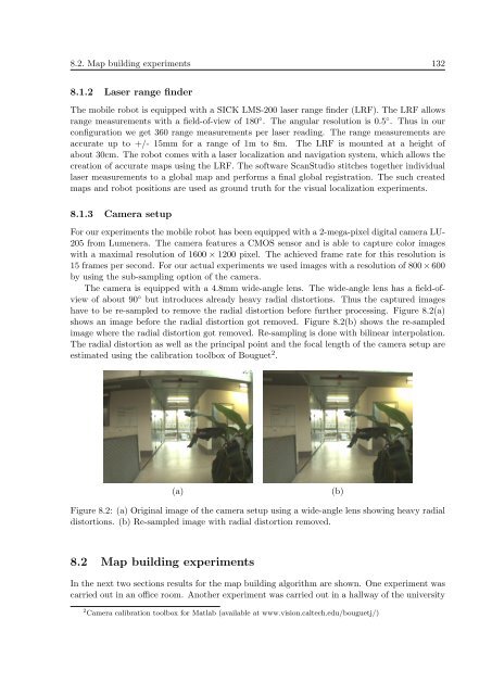
The camera is equipped with a 4.8mm wide-angle lens. The wide-angle lens has a field-ofview<br />
of about 90 ◦ but introduces already heavy radial distortions. Thus the captured images<br />
have to be re-sampled to remove the radial distortion be<strong>for</strong>e further processing. Figure 8.2(a)<br />
shows an image be<strong>for</strong>e the radial distortion got removed. Figure 8.2(b) shows the re-sampled<br />
image where the radial distortion got removed. Re-sampling is done with bilinear interpolation.<br />
The radial distortion as well as the principal point <strong>and</strong> the focal length of the camera setup are<br />
estimated using the calibration toolbox of Bouguet 2 .<br />
(a)<br />
(b)<br />
Figure 8.2: (a) Original image of the camera setup using a wide-angle lens showing heavy radial<br />
distortions. (b) Re-sampled image with radial distortion removed.<br />
8.2 Map building experiments<br />
In the next two sections results <strong>for</strong> the map building algorithm are shown. One experiment was<br />
carried out in an office room. Another experiment was carried out in a hallway of the university<br />
2 Camera calibration toolbox <strong>for</strong> Matlab (available at www.vision.caltech.edu/bouguetj/)