Final report EC 135 Family-23 07 12 - EASA
Final report EC 135 Family-23 07 12 - EASA
Final report EC 135 Family-23 07 12 - EASA

You also want an ePaper? Increase the reach of your titles
YUMPU automatically turns print PDFs into web optimized ePapers that Google loves.
<strong>EASA</strong> Eurocopter <strong>EC</strong><strong>135</strong> <strong>Family</strong><br />
EUROPEAN AVIATION SAFETY AGENCY<br />
EXPERT DEPARTMENT / CERTIFICATION DIR<strong>EC</strong>TORATE<br />
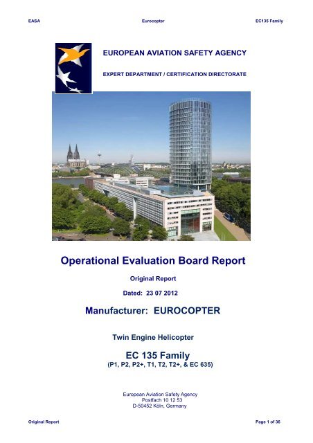
Operational Evaluation Board Report<br />
Original Report<br />
Dated: <strong>23</strong> <strong>07</strong> 20<strong>12</strong><br />
Manufacturer: EUROCOPTER<br />
Twin Engine Helicopter<br />
<strong>EC</strong> <strong>135</strong> <strong>Family</strong><br />
(P1, P2, P2+, T1, T2, T2+, & <strong>EC</strong> 635)<br />
European Aviation Safety Agency<br />
Postfach 10 <strong>12</strong> 53<br />
D-50452 Köln, Germany<br />
Original Report Page 1 of 36
<strong>EASA</strong> Eurocopter <strong>EC</strong><strong>135</strong> <strong>Family</strong><br />
<strong>EC</strong> <strong>135</strong><br />
<strong>EC</strong> 635<br />
Original Report Page 2 of 36
<strong>EASA</strong> Eurocopter <strong>EC</strong><strong>135</strong> <strong>Family</strong><br />
Revision Record<br />
Revision No. Section Pages No. Date<br />
Original Report All All <strong>23</strong>/<strong>07</strong>/20<strong>12</strong><br />
Original Report Page 3 of 36
<strong>EASA</strong> Eurocopter <strong>EC</strong><strong>135</strong> <strong>Family</strong><br />
Contents<br />
• Cover ......................................................................................................................... 1<br />
• Helicopters Pictures ................................................................................................... 2<br />
• Revision Record ......................................................................................................... 3<br />
• Contents ..................................................................................................................... 4<br />
• Operation Evaluation Board – OPS-FCL .................................................................... 5<br />
• Eurocopter experts involved in the process ................................................................ 6<br />
• Executive Summary ................................................................................................... 7<br />
• Acronyms ................................................................................................................... 8<br />
1. Purpose and applicability.......................................................................................... 10<br />
2. General Description of all <strong>EC</strong> <strong>135</strong> & <strong>EC</strong> 635 variants .............................................. 11<br />
3. Helicopter Main Characteristics ................................................................................ 22<br />
4. Operator Differences Requirement (ODR) Tables .................................................... <strong>23</strong><br />
5. Optional specific equipment ..................................................................................... <strong>23</strong><br />
6. Master Differences Requirements ............................................................................ 24<br />
7. Type Rating List and Licence Endorsement List ....................................................... 26<br />
8. Specification for Training .......................................................................................... 26<br />
9. Specification for Testing, Checking, Currency & Recent experience ........................ 36<br />
10. Specification for Flight Simulation Training Devices ................................................. 36<br />
11. Application of OEB <strong>report</strong> ......................................................................................... 36<br />
<strong>12</strong>. Appendices .............................................................................................................. 36<br />
Original Report Page 4 of 36
<strong>EASA</strong> Eurocopter <strong>EC</strong><strong>135</strong> <strong>Family</strong><br />
Operational Evaluation Board – OPS / FCL Subgroup<br />
Jean-Marc SACAZES<br />
<strong>EASA</strong> – Section Manager<br />
Operational Suitability Rotorcraft / Balloons / Airships<br />
Experts department- Certification Directorate<br />
Original Report Page 5 of 36
<strong>EASA</strong> Eurocopter <strong>EC</strong><strong>135</strong> <strong>Family</strong><br />
Name<br />
Joachim BALIK<br />
Eurocopter Experts involved in the process<br />
Position<br />
Head of Training - FTO<br />
Office / Branch<br />
Eurocopter Deutschland<br />
Jürgen Hackbarth Chief Flight Instructor- FTO Eurocopter Deutschland<br />
Rene NATER<br />
Robert Haas<br />
Test Pilot –<br />
Program <strong>EC</strong><strong>135</strong><br />
Eurocopter Deutschland<br />
Certification Manager Eurocopter Deutschland<br />
Remarks<br />
Original Report Page 6 of 36
<strong>EASA</strong> Eurocopter <strong>EC</strong><strong>135</strong> <strong>Family</strong><br />
1. Manufacturer Application<br />
Executive Summary<br />
Eurocopter Manufacturer has made a formal application to <strong>EASA</strong> Experts Department -<br />
Certification Directorate to an OEB catch up process for the evaluation of initial and Additional Type<br />
Ratings and Difference training courses between all variants and in both ways of the “<strong>EC</strong> <strong>135</strong><br />
<strong>Family</strong>”.<br />
In addition Eurocopter has requested to evaluate the military variant <strong>EC</strong> 635 T1, P2+, T2+, literally<br />
the same helicopter like the <strong>EC</strong><strong>135</strong> but with additional military specifications, to consider as<br />
variants of the <strong>EC</strong><strong>135</strong> <strong>Family</strong>. Those three models are already included in the same <strong>EASA</strong><br />
TCDS.R009.<br />
2. OEB recommendations<br />
The OEB recommends for approval by NAAs<br />
• Update Type Rating List & Licence Endorsement List<br />
• Pilot Initial Type Rating Training minimum syllabus<br />
• Pilot Additional Type Rating Training minimum syllabus<br />
• Instrument Rating Extension<br />
• Difference Training minimum syllabus<br />
• Currency and Recent experience<br />
• Training area of special emphasis<br />
3. Procedures, requirements and associated AMC references<br />
The <strong>EASA</strong> – Section Manager Operational Suitability Rotorcraft / Balloons / Airships<br />
and Eurocopter Helicopter experts have participated actively to this evaluation (Refer to the list page 6).<br />
<strong>EASA</strong> representatives have conducted this OEB in accordance with JAR-OPS 3, Part-FCL and<br />
JAR-FSTD 1H requirements. This evaluation was based on the JOEB Handbook and Common<br />
procedures Document (CPD) and the processes detailed in the JAA Administrative and Guidance<br />
Material, Section One, Part Two, Chapter 5 and Part-FCL including associated appendices, AMC<br />
and GM.<br />
Note on references and reference texts:<br />
Where references are made to requirements and where extracts of reference texts are provided, these are at the<br />
amendment state at the date of publication of the <strong>report</strong>. Readers should take note that it is impractical to update these<br />
references to take account of subsequent amendments to the source documents.<br />
François FABRE<br />
<strong>EASA</strong> – Deputy Head of Expert Department<br />
Certification Directorate<br />
Original Report Page 7 of 36
<strong>EASA</strong> Eurocopter <strong>EC</strong><strong>135</strong> <strong>Family</strong><br />
General<br />
Acronyms<br />
AC Alternate Current (electrical)<br />
AEO All Engines Operative<br />
AFCS Automatic Flight Control System (Autopilot)<br />
AMC Acceptable Means of Compliance<br />
AOC Aircraft Operator Certificate<br />
ARIS Anti Resonance Isolation System<br />
ATPL (H) Airline Transport Pilot Licence (Helicopter)<br />
ATO Approved Training Organisation<br />
ATR Additional Type Rating<br />
CPD Common Procedures Document (for FAA-TCCA-FAA)<br />
CDS Cockpit Display System<br />
CPDS Central Panel Display System<br />
CPL (H) Commercial Pilot Licence (Helicopter)<br />
DC Direct Current (electrical)<br />
<strong>EASA</strong> European Aviation Safety Agency<br />
<strong>EC</strong>D Eurocopter Deutschland<br />
<strong>EC</strong>U Engine Control Unit<br />
E<strong>EC</strong>U Electronic Engine Control Unit<br />
EFIS Electronic Flight Instrument System<br />
EMB Electrical Master Box<br />
EPU External Power Unit<br />
FAD<strong>EC</strong> Full Authority Digital Engine Control<br />
FCDS Flight Control Display System (digital flight instruments)<br />
FLI First Limit Indicator<br />
FLM Flight Manual<br />
FTD Flight Training Device<br />
FNPT Flight and Navigation Procedure Trainer<br />
FRP Fibre Reinforced Plastic<br />
FSTD Flight Simulation Training Device<br />
FTO Flying Training Organisation<br />
GM Guidance Material<br />
GPU Ground Power Unit<br />
IFR Instrument Flight Rules<br />
IR Instrument Rating<br />
ITR Initial Type Rating<br />
JAA Joint Aviation Authority<br />
JAR-FCL 1 Joint Aviation Requirements – Flight Crew Licenses (Aeroplane)<br />
JAR-FCL 2 Joint Aviation Requirements – Flight Crew Licenses (Helicopter)<br />
JAR-OPS 3 Joint Aviation Requirements Operations 3 (Helicopter commercial air transport)<br />
JOEB Joint Operational Evaluation Board<br />
MDR Master Difference Requirements<br />
MEH Multi Engine Helicopter<br />
MEL Minimum Equipment List<br />
MET Multi Engine Turbine<br />
MGB Main Gear Box<br />
MMEL Master Minimum Equipment List<br />
MSL Mean Sea Level<br />
Original Report Page 8 of 36
<strong>EASA</strong> Eurocopter <strong>EC</strong><strong>135</strong> <strong>Family</strong><br />
NAAs National Aviation Authorities<br />
N/A Not Applicable<br />
ODR Operator Differences Requirements<br />
OEI One Engine Inoperative<br />
OEB Operational Evaluation Board<br />
PPL (H) Private Pilot Licence (Helicopter)<br />
RPM Revolutions per Minute<br />
TGB Tail rotor Gear Box<br />
TRI (H) Type Rating Instructor (Helicopter)<br />
T/R Tail Rotor<br />
TRTC Type Rating Training Course<br />
TRTO Type Rating Training Organisation<br />
VEMD Vehicle and Engine Monitoring Display<br />
VNE Velocity - Never Exceed<br />
VTOSS Velocity Take Off Safety Speed<br />
Vy Velocity - for best rate of climb<br />
Vx Velocity - for best angle of climb<br />
YAW-SAS Yaw – Stability Augmentation System<br />
WAT Weight Altitude Temperature<br />
Helicopter Model designators along historic evolution within EADS group<br />
AS Aerospatiale<br />
BO Bölkow (MBB / Messerschmidt Bölkow Blohm)<br />
BK Bölkow / Kawasaki<br />
<strong>EC</strong> Eurocopter<br />
SA Sud Aviation<br />
SE Société Nationale de Constructions Aéronautiques du Sud-Est<br />
SO Société Nationale de Constructions Aéronautiques du Sud-Ouest<br />
Original Report Page 9 of 36
<strong>EASA</strong> Eurocopter <strong>EC</strong><strong>135</strong> <strong>Family</strong><br />
I. Purpose and applicability<br />
Data is being submitted by Eurocopter in support of the catch up OEB process concerning<br />
differences between the helicopters: <strong>EC</strong><strong>135</strong> P1, P2, P2+ or T1, T2, T2+ and <strong>EC</strong>635 T1, P2+, T2+.<br />
The operator difference tables (ODR) provided by the manufacturer include a comparison of the <strong>EC</strong> <strong>135</strong><br />
family (See Appendix 4).<br />
The basic <strong>EC</strong>635 is essentially an <strong>EC</strong><strong>135</strong> under military certification and only differs to a civilian<br />
<strong>EC</strong><strong>135</strong> by a reinforced side shell. Since the <strong>EC</strong>635 variants (T1,P2+ & T2+) are identical and<br />
already included in <strong>EASA</strong> TCDS.R005, specific <strong>EC</strong>635 ODR tables are not developed and the<br />
same ODR tables apply as used for <strong>EC</strong><strong>135</strong> (see MDR Table page 24)<br />
Note:<br />
To enable an easy reading of this <strong>report</strong>, the <strong>EC</strong><strong>135</strong> P1, P2, P2+, T1, T2, T2+ and <strong>EC</strong>635 T1, P2+, T2+, are<br />
sometimes named and grouped under “<strong>EC</strong> <strong>135</strong> <strong>Family</strong>”.<br />
This <strong>report</strong> is the result of a catch up process evaluation which has been made by analysis and<br />
comparison, based on Pilot Initial and Additional Type Rating Training syllabus for all variants<br />
of the <strong>EC</strong> <strong>135</strong> provided by Eurocopter Training Academy and FTOs’ already approved by LBA<br />
(Germany) and by other NAA’s.<br />
This document:<br />
� Provides a general description of all the <strong>EC</strong> <strong>135</strong> <strong>Family</strong><br />
� Updates the Type Rating List and Licence Endorsement List including all <strong>EC</strong> <strong>135</strong> variants<br />
� Makes recommendations for minimum training syllabus for the <strong>EC</strong><strong>135</strong> <strong>Family</strong> to:<br />
� initial type rating (ITR)<br />
� additional type rating (ATR)<br />
� Instrument Rating Extension (IR)<br />
� differences training<br />
� Currency and Recent experience<br />
� Training area of special emphasis<br />
Note:<br />
All variants / models : <strong>EC</strong><strong>135</strong> P1 (CDS); <strong>EC</strong> <strong>135</strong> P1 (CPDS) ; <strong>EC</strong><strong>135</strong> P2 (CPDS); <strong>EC</strong><strong>135</strong> P2+; <strong>EC</strong><strong>135</strong> T1 (CDS) ; <strong>EC</strong><br />
<strong>135</strong> T1 (CPDS); <strong>EC</strong><strong>135</strong> T2 (CPDS); <strong>EC</strong><strong>135</strong> T2+; <strong>EC</strong> 635 T1 (CPDS) ; <strong>EC</strong> 635 P2+; <strong>EC</strong> 635 T2+, are listed in the Type<br />
Certificate Data Sheet delivered by <strong>EASA</strong> under TCDS.R.009.. (See Appendix 1).<br />
Original Report Page 10 of 36
<strong>EASA</strong> Eurocopter <strong>EC</strong><strong>135</strong> <strong>Family</strong><br />
2. General Description of <strong>EC</strong> <strong>135</strong> <strong>Family</strong><br />
History<br />
To substitute the BO105 after 20 years in duty, the BO108 was developed and flown for the first<br />
time on Oct. 15th, 1988. In late 1992, the design was modified to provide accommodation for more<br />
passengers and cargo, also an Aerospatiale developed Fenestron Anti Torque system was<br />
adapted.<br />
The <strong>EC</strong> <strong>135</strong> - as it looks today - took shape and certification by the German (LBA) and the<br />
American Airworthiness Authorities (FAA) was completed 1996.<br />
General<br />
The <strong>EC</strong> <strong>135</strong> is approved in the Small Rotorcraft Airworthiness Category, under JAR 27 first issue –<br />
06 September 1993,, JAR 27 Appendix C for Category A Operation, and JAR 27 Appendix B for<br />
operation under IFR.<br />
The <strong>EC</strong> <strong>135</strong> is a light twin-engined turbine multi-purpose helicopter, a fully-separated fuel system, a<br />
dual hydraulic system, a dual electrical system and a redundant lubrication system for the main<br />
transmission.<br />
The helicopter in its basic configuration is certified for land operation under day and night Visual<br />
Meteorological Conditions (VMC). With special equipment installed and operative and under<br />
observance of the procedures and limitations, the helicopter is also certified for land operation<br />
under day and night Instrument Meteorological Conditions (IMC).<br />
• Cockpit Display Systems Versions and Flight Instrumentation<br />
<strong>EC</strong><strong>135</strong> variants in their basic configurations may be equipped with two major different cockpit<br />
instrumentations (see pages 18/19):<br />
o CDS (Cockpit Display System) installed up to SN 168, a digital engine and systems<br />
information combined with analogue flight instruments.<br />
o CPDS (Central Panel Display System) installed SN 169 and up, a multifunction digital screen<br />
display combined with analogue flight instruments (or optional FCDS)<br />
OEB has decided that the design and training differences between the two possible flight<br />
instrumentations should be considered essentially as the same variant, however a pilot<br />
familiarisation training may be necessary (see the Note on pages 28 or 31)<br />
• Engine Versions<br />
<strong>EC</strong> <strong>135</strong> and <strong>EC</strong> 635 variants are powered by two engines, depending on the designators on the<br />
FLM, respective engine versions are installed:<br />
o <strong>EC</strong> <strong>135</strong> P1 : Pratt & Whitney PW 206 B for (CDS & CPDS)<br />
o <strong>EC</strong> <strong>135</strong> P2 : Pratt & Whitney PW 206 B2<br />
o <strong>EC</strong> <strong>135</strong> P2+: Pratt & Whitney PW 206 B2<br />
o <strong>EC</strong> <strong>135</strong> T1 : Turbomeca 2B1/2B1A/2B1A_1 for (CDS & CPDS)<br />
o <strong>EC</strong> <strong>135</strong> T2 : Turbomeca 2B2<br />
o <strong>EC</strong> <strong>135</strong> T2+ : Turbomeca 2B2<br />
o <strong>EC</strong> 635 T1 : Turbomeca 2B1/2B1A/2B1A_1<br />
o <strong>EC</strong> 635 P2+ : Pratt & Whitney PW 206 B2<br />
o <strong>EC</strong> 635 T2+ : Turbomeca 2B2<br />
These engines are in the 450 KW class and may produce up to max. 526 KW for OEI operations<br />
Original Report Page 11 of 36
<strong>EASA</strong> Eurocopter <strong>EC</strong><strong>135</strong> <strong>Family</strong><br />
For Version P1 and T1 the general maximum take-off mass is 2720 kg.<br />
With OPT 9-1-3 installed (enlarged control range) the MTOM is 2835 kg.<br />
With OPT 9-2-19 (external cargo hook) both versions (P1 and T1) have a MTOM of 2900 kg.<br />
For Version P2 and T2 the general maximum take-off mass is 2835 kg.<br />
With OPT 9-2-19 (external cargo hook) both versions (P2 and T2) have a MTOM of 2900 kg.<br />
For engine versions P2+ and T2+ the general maximum take-off mass is 2910 kg<br />
With OPT 9-2-19 :<br />
• external cargo hook, both versions (P2+ and T2+) have a MTOM of 2910 kg.<br />
• extended gross mass, both versions (P2+ and T2+) have a MTOM of 2950 kg.<br />
Fuselage<br />
The fuselage serves as platform for the helicopter systems, crew, passengers and payload.<br />
The exterior shape of the fuselage is aerodynamically optimized and includes various cowlings<br />
(MGB, Engine, Aft, Tail rotor fairing) and service covers (i.e. Nose, Forward, Middle, Tank, Tail<br />
boom / Fin).<br />
The modular concept simplifies the assembly of the helicopter and permits the replacement of<br />
individual modules without the necessity of disassembling the entire fuselage.<br />
The main components of the fuselage are:<br />
Main fuselage structure (transmission deck, side shells, engine deck, rear attachment cone, cabin<br />
floor, subfloor structure and bottom shell) It is the part of the fuselage that carries all the loads<br />
transmitted by the main transmission, the main rotor system and all loads caused by the engines,<br />
landing gear and tail unit.<br />
It consists of the body structure and floor structure. The structures are predominantly produced as<br />
aluminium-alloy body structures which are rigidly attached to each other.<br />
The transmission deck takes up the load of the lifting system and consists of frames 4 thru 5 as well<br />
as longitudinal beams. It is attached by rivets to the side panels and includes six mounts for the<br />
main transmission installation.<br />
The engine deck, which supports the engines, consists of frames 6 and 7 and longitudinal beams. It<br />
is riveted to the transmission deck and to the side panels. The engine deck is equipped with<br />
mounts to which the engine is attached through its mounting struts.<br />
Integral with the upper surface of the engine deck is the rear structure attachment cone.<br />
As the engine deck is part of the firewall-system, the skin is made from titanium sheet metal.<br />
Cabin structure (cabin frame and roof structure)<br />
It is a one-piece structural component, constructed as a hollow profile made of composite material,<br />
mainly carbon-fiber, but also glasfiber and KEVLAR is used. The framework provides the structural<br />
support for mounting the windshields, the nose windows, the pilot/copilot doors and the sliding<br />
doors to the passenger compartment.<br />
Rear structure (tail boom with horizontal stabilizer and Fenestron structure)<br />
The rear structure is connected to the main fuselage structure through connecting frame 8 which is<br />
riveted to the attachment cone. It stabilizes the helicopter in flight through a vertical fin and contains<br />
an integrated Fenestron tail rotor. The rear structure is a sandwich design made<br />
of carbon glass hybrid preprag with NOMEX core inside.<br />
Doors and service covers<br />
The helicopter fuselage is fitted with six doors to provide access to the cockpit, passenger cabin<br />
and cargo compartment. The doors are a carbon-glass-fiber composite construction.<br />
Original Report Page <strong>12</strong> of 36
<strong>EASA</strong> Eurocopter <strong>EC</strong><strong>135</strong> <strong>Family</strong><br />
Landing gear<br />
The landing gear carries the weight of the helicopter on the ground and absorbs landing impact<br />
loads. It is attached through four fittings and bearing rings to the floor structure of the fuselage. It is<br />
made of aluminium and consists of two cross tubes and two skids which are clamped together with<br />
skid shoes.<br />
To prevent the fuselage from being over-stressed during touch down, the bearing rings on the cross<br />
tubes are swivelling in their brackets so that all forces are absorbed by bending the cross tubes<br />
only.<br />
A skid track of 2 m, the rigid construction of the landing gear and the hinge less main rotor provides<br />
the helicopter with good stability when on the ground and disables ground resonances.<br />
The landing gear may be fitted with optional equipments like emergency flotation system, FLIR, etc.<br />
A high- or intermediate landing gear is available to meet changing operational requirements.<br />
Seating<br />
In its basic configuration the <strong>EC</strong><strong>135</strong> series features a 7 seat arrangement.<br />
Cockpit<br />
There are 2 crew seats in the cockpit of which the copilot seat on the left hand side may be used as<br />
passenger seat during single pilot operations. The seats are supported by longitudinal slide rails<br />
and are fixed each by four sliding shoes.<br />
Cabin<br />
In the forward cabin section are 3 passenger seats facing aft to the flight direction, mounted on a<br />
high support frame.<br />
In the aft section of the cabin are 2 passenger seats facing forward to the flight direction, mounted<br />
RH and LH side of the cabin. Each of the seats is mounted on two support bars which are fixed in<br />
the seat tracks on the aft cabin floor.<br />
Several other seat arrangements are certified and described in the optional section of the flight<br />
manual<br />
Main Rotor and blades<br />
The main rotor system consists of a bearing-less, hinge-less 4-bladed main rotor, a main rotor shaft<br />
with integral hub, control elements, and the rotor-related indicators.<br />
By using modern composite materials, this rotor system provides flapping, lead-lag and blade pitch<br />
change functions without the need of complicated ball and elastomeric bearings.<br />
Main Rotor Blades<br />
The main rotor blades are manufactured with fiber composite materials. A blade root (Flex Beam)<br />
with low bending and torsion stiffness enables the same functions like flap- and lead-lag hinges as<br />
well as the function of blade pitch bearings.<br />
A pitch control cuff around the flex beam is integrated in the blade structure to provide a rigid<br />
connection with the airfoil section of the blade. The pitch angle of the main rotor blade is changed<br />
through a pitch horn on the pitch control cuff. The pitch control cuff is kept centred around the blade<br />
root by a bearing support and a spherical bearing.<br />
Two elastomeric lead-lag dampers provide sufficient in-plane damping of the main rotor blade to<br />
prevent ground and air resonance.<br />
The airfoil section has a rectangular blade geometry with a parabolic swept-back tip and a negative<br />
2° twist per meter. The blade airfoil consists of:<br />
- a homogenous section comprising the DM--H4 airfoil up to R = 4500 mm<br />
- a transition area between R = 4500 and R = 4800 mm with DM--H4 and DM--H3 airfoil<br />
Original Report Page 13 of 36
<strong>EASA</strong> Eurocopter <strong>EC</strong><strong>135</strong> <strong>Family</strong><br />
- the blade tip between R = 4800 and R = 5100 mm comprising the DM--H3 airfoil.<br />
Each blade is equipped with a blade tip mass, static discharger, trim tabs and balance washers.<br />
The blades are protected against leading edge erosion and lightning.<br />
Main Rotor Hub Shaft<br />
The main rotor hub shaft, which is hollow and is formed with two hub flanges at its upper end, is<br />
forged as one-piece and made of steel alloy. The hub flanges allow the attachment of the main<br />
rotor blades. On these flanges, the rotor blades are connected, thus eliminating the need of a rotor<br />
head.<br />
Control Elements<br />
A swashplate is used to connect the rotor to the stationary components of the control system.<br />
It is mounted to a sliding sleeve, free to slide on a main gearbox mounted support tube.<br />
Two scissor assemblies enable a synchronous rotation of the swashplate bearing ring with the rotor<br />
mast. Four rotating control rods enable the control inputs from the swashplate to the main rotor<br />
blades.<br />
Rotor related Indications<br />
The indicating system consists of a rotor RPM indicator, a visual and aural rotor RPM warning and<br />
a mast moment indication.<br />
The rotor RPM is sensed with an inductive system. The signal is processed to a warning unit and<br />
indicated in a rotor RPM indicator. It works as long as electrical power is supplied to the helicopter.<br />
Through the warning unit the pilot is warned by a warning light and aural signal when passing<br />
minimum, high or maximum rotor RPM.<br />
Since the main motor system is a hinge less / bearing less system, the rotor mast has to carry<br />
certain bending moments during slope landings or very rapid control inputs. To indicate such rotor<br />
mast bending moments a Mast Moment (MM) indication system is installed.<br />
Tail Rotor<br />
The vertical fin together with the integral Fenestron structure forms a unit. The upper region of the<br />
vertical fin has an aerodynamic function, while the Fenestron structure below encloses the tail rotor<br />
system. With this design and sufficient forward speed, the helicopter is able to continue to fly even<br />
in case of a tail rotor drive failure.<br />
The tail rotor is a shrouded fan-in-fin rotor (Fenestron concept) which is installed in a duct in the<br />
Fenestron structure which is part of the tail fin and made of composite material. A stator is installed<br />
in the duct of the Fenestron structure to which the tail rotor gearbox is attached.<br />
The tail rotor is equipped with ten unevenly-spaced rotor blades. This design produces overlapping<br />
acoustic vibrations which in turn creates a low noise level.<br />
Drive System<br />
The drive system transmits engine power to the Main Rotor, to the Tail Rotor drive and to its<br />
associated auxiliary units (like HYD pumps / Oil cooler fans etc.).<br />
As the engines are free turbine type engines, there is no clutch. A free wheel is integrated in each<br />
main transmission input drive, enabling independent drive of one or two engines as well as<br />
autorotation of the main transmission gear above the engine input speed.<br />
The engines output rotates with approx. 5900 RPM (at 100% N2) which is reduced to 395 RPM for<br />
the Main rotor and to 4986 for the Tail rotor drive output.<br />
The tail rotor gearbox reduces the RPM further down to 3584 used by the Tail rotor.<br />
The drive system consists of:<br />
Engine Driveshaft’s<br />
The driveshafts transmit the power of the engines to the main transmission. They connect the<br />
engines with the freewheeling units of the main transmission. In addition, they correct for any<br />
Original Report Page 14 of 36
<strong>EASA</strong> Eurocopter <strong>EC</strong><strong>135</strong> <strong>Family</strong><br />
variations in length or misalignment between the engine outputs and the main transmission inputs.<br />
For this purpose two flexible couplings are attached to each end of the driveshaft.<br />
Main transmission<br />
The main transmission transfers the power from both engines to the main rotor system, tail rotor<br />
drive and to the auxiliary units. All mounting points, attachment fittings and oil lines are integrated<br />
into the transmission casing. It contains a wet sump oil system for lubrication and cooling. Because<br />
of redundancy, the lubrication system comprises two oil pumps located in the lower casing of the<br />
gearbox. A connecting pad at the tail rotor drive provides the attachment point for the rotor brake<br />
disc adapter and the tail rotor driveshaft.<br />
The tail rotor drive transmits the power from the main rotor transmission to the tail rotor through a<br />
system of shafts, flexible couplings and the tail rotor gearbox.<br />
The tail rotor gearbox (TGB) is a single-stage, spiral-toothed bevel gear. The gearbox housing is<br />
made of aluminium alloy. It reduces the speed of the drive shafts and houses the components<br />
which control the tail rotor.<br />
Flight Controls<br />
Main rotor control<br />
Below the cockpit floor, passing a centre post in the cabin to the cabin roof, are control linkages<br />
between cyclic stick and collective pitch which lead to main rotor hydraulic actuators. These<br />
linkages are interconnected with bell-cranks.<br />
Above the cabin are the hydraulic actuators which are bolted to the main transmission. They are<br />
linked to the cyclic stick- and collective linkages on the un-boosted side and to the mixing levers /<br />
swash-plate on the boosted side.<br />
After the swash-plate, rotating control rods are connected to the pitch horn of the blades.<br />
Tail rotor control<br />
The pedal assembly for tail rotor control is connected below the cockpit floor with control rods to a<br />
bell crank lever. From here a ball bearing control cable (Flexball cable) leads to an electrical<br />
actuator which is located inside the Fenestron structure and an integrated part of the YAW-SAS. A<br />
control rod leads from this yaw actuator to an input lever which moves a piston in the Fenestron<br />
Actuator. The inputs are boosted hydraulically and transmitted to the control spider which changes<br />
the blade angles of the Fenestron.<br />
The standard version of the helicopter is fitted with a YAW SAS system which is connected to HYD<br />
system No. 2. The yaw actuator is an actuator with an integral position feedback (SEMA Smart<br />
Electro-Mechanical Actuator). It converts the stabilizing signal produced by a fibre optic gyro (FOG)<br />
into a corresponding mechanical input to the tail rotor control linkage.<br />
Rotor brake<br />
A hydro-mechanical rotor brake system enables the rotors to be brought to a standstill<br />
The rotor brake control lever is installed in front of the overhead panel and equipped with a locking<br />
device. A cable runs to the hydraulic assembly (fluid reservoir / brake cylinder / damper) mounted<br />
on the main transmission. From here a hydraulic line leads to the brake calliper which is mounted<br />
on a brake support on the main transmission above the tail rotor drive.<br />
The tail rotor drive pad provides the attachment point for the rotor brake disc adapter to which the<br />
brake disk is mounted. If the rotor brake lever is locked for a longer period of time, the hydraulic<br />
pressure will slowly decrease and the brake function will be lost with time.<br />
When the brake is active, the calliper moves and touches a micro switch which in turn triggers a<br />
caution light in the CDS/CPDS, indicating that the rotor brake is active.<br />
Original Report Page 15 of 36
<strong>EASA</strong> Eurocopter <strong>EC</strong><strong>135</strong> <strong>Family</strong><br />
Engines<br />
The <strong>EC</strong> <strong>135</strong> is equipped with either two Pratt & Whitney 206 or two Turbomeca ARRIUS engines.<br />
The engines feature small differences in technical design, power output and fuel consumption but in<br />
principle both engines are of modular design and consist of:<br />
- The reduction gearbox module<br />
- Gas generator and power turbine module<br />
- Engine subsystems (Fuel / Oil / Indication)<br />
The PW206 and the ARRIUS<br />
Are a lightweight, free turbine, turbo-shaft engine incorporating a single stage centrifugal<br />
compressor driven by a single stage compressor turbine and a single stage power turbine that<br />
drives a reduction gearbox, means the aircraft power train.<br />
The PW 206 at nominal 100% N2 (39130 RPM - Power Turbine speed) the output drive is reduced<br />
to 5928 RPM.<br />
The ARRIUS at nominal 100% N2 (44038 RPM - Power Turbine speed) the output drive is reduced<br />
to 5898 RPM.<br />
Metered fuel from a Fuel Management Module (FMM) or (FMU) is sprayed into a reverse flow<br />
annular combustion chamber through individual fuel nozzles mounted around the gas generator<br />
case. A high voltage ignition unit and dual spark igniters are used to ignite the fuel during engine<br />
start.<br />
An Electronic Engine Control (E<strong>EC</strong>) or (E<strong>EC</strong>U) system works in conjunction with an electrical<br />
torque motor located within the Fuel Management Module to change the fuel flow as required. This<br />
system ensures an automatic control of the engine output speed and fast response to changes in<br />
power demand.<br />
As emergency backup the fuel flow may be manually changed with a twist grip which in turn is<br />
changing the position of a fuel metering valve in the FMM or FMU.<br />
Note:<br />
Both engines utilize a single channel computerized electronic engine control. Since such systems<br />
are fully automate they are commonly known as FAD<strong>EC</strong>. This designation is used in the helicopter<br />
documentation whenever the electronic engine control system is meant.<br />
Ignition system (engine start)<br />
The engine start of the <strong>EC</strong> <strong>135</strong> is fully automated and controlled by the respective FAD<strong>EC</strong>.<br />
Fuel system<br />
The fuel system comprises two fuel tanks, a fuel supply system, a refueling and grounding<br />
equipment and a monitoring system. The main tank and supply tank with overflow to the main tank<br />
and sufficient separated quantity for approximately 20 minutes flight time are installed under the<br />
cabin floor. Fuel is stored in underfloor compartments using two bladder type fuel cells comprising a<br />
main tank and a supply tank. The supply tank comprises two seperate sections, with different<br />
capacities, each supplying one engine. This ensures that the engines may not fail at the same time<br />
when running out of fuel. From the supply tank, located directly aft of the main tank, fuel is<br />
transferred to the engines. The main and the supply tank are interconnected via spill ports and<br />
transfer lines. The volume above the spill ports of the main and supply tank is a part of the main<br />
tank capacity.<br />
Original Report Page 16 of 36
<strong>EASA</strong> Eurocopter <strong>EC</strong><strong>135</strong> <strong>Family</strong><br />
Electrical System<br />
The electrical power supply systems generate and distribute power for operation and control of the<br />
helicopter systems. The <strong>EC</strong> <strong>135</strong> electrical systems operate on 28 VDC. When supplied by the<br />
battery, they operate on 24 V. An AC system is installed additionally.<br />
The electrical power supply consists of:<br />
- power generation<br />
- external power receptacle<br />
- power distribution<br />
- AC power system.<br />
• Power Generation<br />
The power generation consists of two generators, a battery and the corresponding master<br />
boxes.<br />
• External Power Receptacle<br />
It is possible to supply the electrical power system with DC power by an External Power Unit.<br />
The voltage of the EPU should be adjusted between 24 and 28 VDC.<br />
If the voltage of the EPU is higher than the voltage of the battery, the EPU is automatically<br />
selected as power source. If not, the system will not accept the EPU for power distribution.<br />
• Power Distribution<br />
Several bus bars are installed in the master boxes, the overhead panel and both circuit breaker<br />
panels, to which all electrical consumers of the helicopter are connected by means of circuit<br />
breakers.<br />
• AC Power System<br />
The AC power system generates two different AC voltages (26 VAC, 115 VAC) out of 28 VDC<br />
using static inverters. The helicopter is equipped with one system (SYS 2) as a standard or two<br />
systems (SYS 2 and SYS 1) as an option.<br />
The AC voltages are distributed to the consumers via modules and bus bars. They are used for<br />
navigation instruments and for the Stability Augmentation System (SAS).<br />
Hydraulic System<br />
The hydraulic system is used to boost the manual control inputs of the pilot. Like in many<br />
helicopters, the main rotor system cannot be controlled without hydraulic assistance. For this<br />
reason the system is completely redundant for main rotor control.<br />
Since the tail rotor (Fenestron) may be controlled with higher forces also without hydraulic<br />
assistance, the yaw axis is designed as a simplex system and supplied by HYD system No. 2 only.<br />
The system consists of;<br />
- two identical pressure supply systems (located on top of the main XMSN accessory gear)<br />
- three main rotor actuators (duplex type, installed in front of the main XMSN)<br />
(collective axis = MHA (Mechano Hydraulic Actuator)<br />
(lateral- and longitudinal axis = EHA (Electro Hydraulic Actuator)<br />
- Fenestron actuator (simplex type)<br />
(for yaw axis control, installed inside the stator hub of the Fenestron)<br />
- indicating and testing system<br />
(installed in the cockpit)<br />
Original Report Page 17 of 36
<strong>EASA</strong> Eurocopter <strong>EC</strong><strong>135</strong> <strong>Family</strong><br />
The hydraulic system works with an operating pressure of 103 bar, return pressure 1.40 -- 1.75 bar,<br />
with hydraulic fluid acc. MIL--H 5606 (F) standard.<br />
The fluid capacity of SYS 1 is 1.0 l, SYS 2 is 1.2 l and the reservoir has a capacity of 0.8 l.<br />
It is a closed system, so it is not possible to refill the system without a special tool.<br />
Instrument panels and consoles<br />
Three basic instrument panels exist;<br />
a) Instrument panel with Cockpit Display System ( CPS) and analogue instruments<br />
• Main features of CDS (Cockpit Display System)<br />
Original Report Page 18 of 36
<strong>EASA</strong> Eurocopter <strong>EC</strong><strong>135</strong> <strong>Family</strong><br />
b) Instrument panel with Central Panel Display System (CPDS) and analogue instruments<br />
c) Instrument panel with Central Panel Display System (CPDS) and FCDS<br />
Original Report Page 19 of 36
<strong>EASA</strong> Eurocopter <strong>EC</strong><strong>135</strong> <strong>Family</strong><br />
• Main features of CPDS (Central Panel Display System)<br />
CAD – Caution and Advisory Display (general indication examples)<br />
The VEMD consists of two processing modules (lanes) and two screens combined in a housing.<br />
Upper lane provides for system 1, lower lane for system 2. All input signals are received and<br />
processed by the two processing modules and the results, exchanged through the cross–talk links,<br />
are compared by the two processors. In case of discrepancy a failure message is displayed.<br />
In case of one module failure, all cautions concerning the FAD<strong>EC</strong>, except of FAD<strong>EC</strong> FAIL, are no<br />
longer available. Each processing module receives power from a separate power supply. In case of<br />
a failure of one power supply the remaining power supply can provide power to both processing<br />
modules<br />
Original Report Page 20 of 36
<strong>EASA</strong> Eurocopter <strong>EC</strong><strong>135</strong> <strong>Family</strong><br />
FLI – First Limit Indicator (Upper lane - general indication examples)<br />
EL<strong>EC</strong> / VHC – Electric and Vehicle display (Lower lane - general indication examples)<br />
Original Report Page 21 of 36
<strong>EASA</strong> Eurocopter <strong>EC</strong><strong>135</strong> <strong>Family</strong><br />
Dimensions<br />
2 Engines<br />
Fuel tanks<br />
Air Speed<br />
Rotor Speed<br />
3. Helicopters main characteristics<br />
3.1 Sum up of main characteristics of the <strong>EC</strong><strong>135</strong> and <strong>EC</strong> 635 variants<br />
Fuselage<br />
Main rotor<br />
<strong>EC</strong> <strong>135</strong> P1<br />
(CDS) &(CPDS)<br />
<strong>EC</strong> <strong>135</strong> P2<br />
(CPDS)<br />
(Reading mode, column by column from the left to the right side → )<br />
<strong>EC</strong> <strong>135</strong> P2+<br />
<strong>EC</strong> 635 P2+<br />
<strong>EC</strong> <strong>135</strong> T1<br />
(CDS) & (CPDS)<br />
<strong>EC</strong> 635 T1 (CPDS)<br />
Original Report Page 22 of 36<br />
<strong>EC</strong> <strong>135</strong> T2 (CPDS)<br />
<strong>EC</strong> <strong>135</strong> T2+<br />
<strong>EC</strong> 635 T2+<br />
Length 10.20 m identical identical identical identical identical<br />
Width 1.56 m identical identical identical identical identical<br />
Height 3.51 m identical identical identical identical identical<br />
Diameter<br />
10.20 m identical identical identical identical identical<br />
Tail rotor 1.00 m identical identical identical identical identical<br />
Power ON<br />
Power OFF<br />
Power ON<br />
Autorotation<br />
Absolute VNE<br />
Pratt & Whitney<br />
206 B<br />
till SN 249 = 544 kg<br />
Later SN = 568 kg<br />
Pratt & Whitney<br />
206 B2<br />
568 Kg<br />
identical<br />
identical<br />
Turboméca Arrius<br />
2B1/ 2B1A/ 2B1A_1<br />
till SN 249 = 544 kg<br />
Later SN = 568 kg<br />
Turbomeca Arrius<br />
2B2<br />
568 Kg<br />
identical<br />
identical<br />
155 kt identical identical identical identical identical<br />
OEI= 110 kt<br />
AR = 90 Kt<br />
100%<br />
+ 4% / - 5%<br />
100 %<br />
+ <strong>12</strong>% / - 15%<br />
identical identical identical identical identical<br />
100%<br />
+ 4% / - 3%<br />
identical<br />
100%<br />
+ 4% / - 5%<br />
100%<br />
+ 4% / - 3%<br />
identical<br />
identical identical identical identical identical<br />
Maximum Operating Pressure Altitude 20000 ft identical identical identical identical identical<br />
MTOW with Internal<br />
load<br />
MTOW with External<br />
load<br />
Category A<br />
Density<br />
Altitude<br />
Clear<br />
Heliport<br />
VTOL<br />
operations<br />
2720 kg but with OPT<br />
9.1-3 2835 kg<br />
2835 kg<br />
2910 kg but with OPT<br />
9.1-6 2950 kg<br />
2720 kg but with OPT<br />
9.1-3 2835 kg<br />
2835 kg<br />
2910 kg but with OPT<br />
9.1-6 2950 kg<br />
2900kg 2910 Kg identical 2900kg 2910 Kg identical<br />
8000 ft <strong>12</strong>000 ft identical 8000 ft<br />
<strong>12</strong>000 ft<br />
identical<br />
5000 ft 8000 ft identical 8000 ft identical identical
<strong>EASA</strong> Eurocopter <strong>EC</strong><strong>135</strong> <strong>Family</strong><br />
3.2 Exterior Dimension<br />
4. Operator Difference Requirement (ODR) Tables<br />
Operator Difference Requirement tables have been produced by EUROCOPTER to evaluate<br />
through the OEB catch up process the entire “<strong>EC</strong><strong>135</strong> family“ for Pilot Initial and Additional Type<br />
Rating Training course and also Difference Training courses. (See Appendix 5).<br />
5. Optional specific equipment<br />
No optional equipment is provided requiring specific training according PART-FCL regulation.<br />
Original Report Page <strong>23</strong> of 36
<strong>EASA</strong> Eurocopter <strong>EC</strong><strong>135</strong> <strong>Family</strong><br />
6. Master Differences Requirements:<br />
6.1 Difference Level Summary.<br />
The Common Procedures Document (CPD) describes one acceptable method and guidelines for<br />
conducting an Operational Evaluation of an aircraft type or a variant certificated. As such the<br />
document offers an acceptable method for compliance with the intent of the applicable regulatory<br />
requirements.<br />
The methods and guidelines presented in this document are not the only acceptable methods for<br />
ensuring compliance with the appropriate regulatory sections. Operators may use other methods if<br />
those methods will provide the necessary level of safety and are acceptable to the regulatory<br />
authority.<br />
Difference levels are summarised in the table below for training, checking, and currency. This table is<br />
an extract only and complete descriptions of difference levels for training, checking and currency are<br />
given in OPS/FCL Common Procedures for conducting Operational Evaluation Boards document.<br />
DIFFERENCE LEVEL TABLE<br />
DIFFERENCE<br />
LEVEL<br />
A SELF INSTRUCTION<br />
B<br />
C<br />
D<br />
E<br />
TRAINING CH<strong>EC</strong>KING<br />
AIDED<br />
INSTRUCTION<br />
SYSTEMS DEVICES<br />
MANOEUVRE<br />
DEVICES**<br />
SIMULATOR C/D OR<br />
AIRCRAFT #<br />
NOT APPLICABLE<br />
(OR INTEGRATED<br />
WITH NEXT PC)<br />
TASK OR SYSTEM<br />
CH<strong>EC</strong>K<br />
PARTIAL CH<strong>EC</strong>K<br />
USING DEVICE<br />
PARTIAL PC USING<br />
DEVICE<br />
FULL PC USING<br />
SIMULATOR C/D OR<br />
AIRCRAFT<br />
CURRENCY/ R<strong>EC</strong>URRENT<br />
TRAINING<br />
NOT APPLICABLE<br />
SELF REVIEW<br />
DESIGNATED SYSTEM<br />
DESIGNATED<br />
MANOEUVRE(S)<br />
AS PER REGULATIONS<br />
(TAKEOFFS & LANDINGS<br />
IN SIMULATOR C/D OR<br />
THE AIRCRAFT)<br />
PC = means Proficiency Check (i.e. LST, LPC or OPC)<br />
Full Flight Simulator or aircraft may be used to accomplish specific manoeuvres<br />
6.2. Training, Checking, and Recurrent Training difference requirements<br />
The Common Procedures Document has been established basically for fixed wing evaluations, so it<br />
appears that adaptations and alleviations to comply with JAR-FCL and to PART-FCL regulation,<br />
specific elements dedicated to helicopter are necessary.<br />
Numbers of regulatory OPS / FCL and operational aspects concern typically helicopter matters like:<br />
o At least one hour flying time for Multi Engine type difference training<br />
o No Helicopter class Rating<br />
o Limited number of available Flight Simulation Training Device<br />
Original Report Page 24 of 36
<strong>EASA</strong> Eurocopter <strong>EC</strong><strong>135</strong> <strong>Family</strong><br />
The Master Difference Requirement tables (MDR) for the “<strong>EC</strong><strong>135</strong> <strong>Family</strong>“have been basically<br />
produced by Eurocopter.<br />
To helicopter<br />
<strong>EC</strong> <strong>135</strong> P1<br />
(CDS) &(CPDS)<br />
<strong>EC</strong> <strong>135</strong> P2<br />
(CPDS)<br />
<strong>EC</strong> <strong>135</strong> P2+<br />
and<br />
<strong>EC</strong> 635 P2+<br />
<strong>EC</strong> <strong>135</strong> T1<br />
(CDS)&(CPDS)<br />
and<br />
<strong>EC</strong> 635 T1<br />
(CPDS)<br />
<strong>EC</strong> <strong>135</strong> T2<br />
<strong>EC</strong> <strong>135</strong> P1<br />
(CDS)&(CPDS)<br />
<strong>EC</strong> <strong>135</strong> P2<br />
(CPDS)<br />
From Helicopter<br />
↓<br />
<strong>EC</strong> <strong>135</strong> P2+<br />
<strong>EC</strong> 635 P2+<br />
<strong>EC</strong> <strong>135</strong> T1<br />
(CDS)&(CPDS)<br />
<strong>EC</strong> 635 T1<br />
(CPDS)<br />
These requirements are related to a standard <strong>EC</strong><strong>135</strong> with analog instruments and do not include<br />
FCDS, AFCS or special NAV equipment like FMS. Such Systems are non-standard equipment but<br />
widely used and therefore taken into account under paragraph 8 where additional training is required.<br />
OEB has concluded that the Master Differences Requirements are at levels D/D/D.<br />
<strong>EC</strong> <strong>135</strong> T2<br />
(CPDS)<br />
<strong>EC</strong> <strong>135</strong> T2+<br />
<strong>EC</strong> 635 T2+<br />
N/A A / A / A A / A / A D / D / D D / D / D D / D / D<br />
A / A / A N/A A / A / A D / D / D D / D / D D / D / D<br />
A / A / A A / A / A N/A D / D / D D / D / D D / D / D<br />
D / D / D D / D / D D / D / D N/A A / A / A A / A / A<br />
(CPDS) D / D / D D / D / D D / D / D A / A / A N/A A / A / A<br />
<strong>EC</strong> <strong>135</strong> T2+<br />
and<br />
<strong>EC</strong> 635 T2+<br />
D / D / D D / D / D D / D / D A / A / A A / A / A N/A<br />
The main element which requires a level “D” difference training, checking and currency is the Engine<br />
governing differences related to FAD<strong>EC</strong> operation and emergencies.<br />
The Operational Evaluation Board has considered the <strong>EC</strong><strong>135</strong> P1-CDS/CPDS, P2-CPDS, P2+,<br />
T1-CDS/CPDS, T2-CPDS, T2+ and recommends to classify also their identical military versions<br />
called “<strong>EC</strong>635 T1, P2+, T2+.” as “variants” of the “<strong>EC</strong><strong>135</strong>” and not as other types. Therefore<br />
they are included in the “<strong>EC</strong> <strong>135</strong> <strong>Family</strong>” (See paragraphs 7 and 8.5).<br />
Original Report Page 25 of 36
<strong>EASA</strong> Eurocopter <strong>EC</strong><strong>135</strong> <strong>Family</strong><br />
7. Type Rating List<br />
The proposal of this OEB is to update the Type Rating List (Helicopters) as follows:<br />
• Table 9 / Type Rating List (Helicopters)<br />
1<br />
Manufacturer<br />
Eurocopter<br />
-ME Turbine -<br />
2<br />
Helicopter<br />
<strong>EC</strong> <strong>135</strong> P1 CDS<br />
<strong>EC</strong> <strong>135</strong> P1 CPDS<br />
<strong>EC</strong> <strong>135</strong> P2 CPDS<br />
<strong>EC</strong> <strong>135</strong> P2+<br />
<strong>EC</strong> 635 P2+<br />
<strong>EC</strong> <strong>135</strong> T1 CDS<br />
<strong>EC</strong> <strong>135</strong> T1 CPDS<br />
<strong>EC</strong> 635 T1 CPDS<br />
<strong>EC</strong> <strong>135</strong> T2 CPDS<br />
<strong>EC</strong> <strong>135</strong> T2+<br />
<strong>EC</strong> 635 T2+<br />
3 4<br />
Licence endorsement<br />
Original Report Page 26 of 36<br />
(D)<br />
<strong>EC</strong> <strong>135</strong>/635<br />
This table 9 matrix contains only Helicopters that have been evaluated through a JOEB, an OEB or a Catch-Up process. Associated<br />
<strong>report</strong>s are published on the <strong>EASA</strong> –Expert Department / Certification Directorate Website and Pilot Training courses are available from<br />
the Manufacturers<br />
8. Specification for Training<br />
8.1 General<br />
The Type Rating Training courses proposed by Eurocopter Deutschland Training Academy for the<br />
<strong>EC</strong><strong>135</strong> <strong>Family</strong> fulfill the minimum requirements of <strong>EASA</strong> Part-FCL. This Training Academy provides a<br />
variety of training and conversion training courses.<br />
The assessment is based on the <strong>EC</strong><strong>135</strong> <strong>Family</strong> Pilot Initial and Additional Type Rating Training<br />
syllabi, and as well the difference training between variants proposed by Eurocopter Deutschland<br />
Training Academy approved by LBA Germany and to Training courses from other European TRTOs’<br />
already approved by their national Authorities.<br />
OEB recommends Pilot training syllabi divided into the following phases for approval in Approved<br />
Training Organizations, like FTO and TRTO:<br />
• Prerequisites for entry onto the specific course<br />
• Theoretical knowledge instruction syllabus and test summary<br />
• Helicopter flight training courses<br />
• FSTD flight training courses (when available)<br />
• Additional Synthetic Training Device instructions (i.e. Avionic Trainer, if available)<br />
• Skill test
<strong>EASA</strong> Eurocopter <strong>EC</strong><strong>135</strong> <strong>Family</strong><br />
8.2 Course pre-entry requirements<br />
For the issue of a first type rating for a single-pilot multi-engine helicopter, all students must fulfil the<br />
pre-entry requirements of the Part –FCL.720.H(c):<br />
8.3 Licensing requirements<br />
The AMC2 FCL.725 (a) of the Part –FCL requires for an Initial issue of a SPH, MET (H) CS and FAR<br />
27 and 29 , an approved flight instruction of at least 8 flight hours in the helicopter or when using<br />
FTD 2/3, at least 4 hours in helicopter and at least 10 hours in total excluding skill test. (See<br />
Appendix 2).<br />
Note:<br />
These requirements have to be considered as the bare minimum, additional training could be necessary<br />
depending on:<br />
• complexity of the aircraft type, handling caracteristics, level of technology<br />
• previous experience of the applicant<br />
• the availability of FSTDs<br />
8.4 Initial, Additional Type Rating & Difference training courses<br />
8.4.1 Initial Type Rating (ITR)<br />
Candidates for the Initial <strong>EC</strong><strong>135</strong> <strong>Family</strong> Type Rating must:<br />
• Hold a valid Helicopter Pilot license,<br />
• Hold a Single-Engine Piston / Turbine Pilot Type Rating<br />
• Comply with the requirements set out in Part –FCL Subpart H – Section 1 & 3.<br />
• Have 70 Flight Hours as PIC<br />
• In case of a PPL(H) license holder: hold a Multi Engines Turbine pre-entry course.<br />
8.4.2 Additional Type Rating (ATR)<br />
Candidates for an Additional <strong>EC</strong><strong>135</strong> <strong>Family</strong> Type Rating must:<br />
• Hold a valid Pilot license,<br />
• Hold a Multi-Engine Turbine Pilot Type Rating<br />
• Comply with the requirements set out in Part FCL Subpart H – Section 1 & 3.<br />
Original Report Page 27 of 36
<strong>EASA</strong> Eurocopter <strong>EC</strong><strong>135</strong> <strong>Family</strong><br />
8.4.3 Difference training courses in between variants:<br />
To<br />
<strong>EC</strong> <strong>135</strong> P1<br />
(CDS)<br />
&(CPDS)<br />
<strong>EC</strong> <strong>135</strong> P2<br />
(CPDS)<br />
<strong>EC</strong> <strong>135</strong> P2+<br />
and<br />
<strong>EC</strong> 635 P2+<br />
<strong>EC</strong> <strong>135</strong> T1<br />
(CDS)&(CPD<br />
S)<br />
and<br />
<strong>EC</strong> 635 T1<br />
(CPDS)<br />
<strong>EC</strong> <strong>135</strong> T2<br />
(CPDS)<br />
<strong>EC</strong> <strong>135</strong> T2+<br />
and<br />
<strong>EC</strong> 635 T2+<br />
<strong>EC</strong> <strong>135</strong><br />
P1<br />
(CDS)<br />
&(CPDS)<br />
<strong>EC</strong><strong>135</strong><br />
P2<br />
(CPDS)<br />
<strong>EC</strong> <strong>135</strong><br />
P2+<br />
And<br />
<strong>EC</strong> 635<br />
P2+<br />
∆ 1 ∆ 2 ∆ 3<br />
From<br />
↓<br />
<strong>EC</strong> <strong>135</strong><br />
T1<br />
(CDS)&(CPDS)<br />
and<br />
<strong>EC</strong> 635<br />
T1<br />
(CPDS)<br />
<strong>EC</strong> <strong>135</strong><br />
T2<br />
(CPDS)<br />
(∆ 1) From P1 CDS / CPDS to T1 CDS / CPDS, T2 CPDS or T2+<br />
(∆ 2) From P2 CPDS to T1 CDS / CPDS, T2 CPDS or T2+<br />
(∆ 3) From P2+ to T1 CDS / CPDS, T2 CPDS or T2+<br />
(∆ 4) From T1 CDS / CPDS to P1 CDS / CPDS, P2 CPDS or P2+<br />
(∆ 5) From T2 CPDS to P1 CDS / CPDS, P2 CPDS or P2+<br />
(∆ 6) From T2+ to P1 CDS / CPDS, P2 CPDS or P2+<br />
<strong>EC</strong> <strong>135</strong><br />
T2+<br />
and<br />
<strong>EC</strong> 635<br />
T2+<br />
∆ 4 ∆ 5 ∆ 6<br />
Note:<br />
Basic differences of CDS and CPDS systems are explained during the initial type rating course. If the one or<br />
other is not flown for a longer period, familiarisation training can adequately be addressed through Selfinstruction<br />
and has to be performed and needs approximately 3 hours.<br />
Original Report Page 28 of 36
<strong>EASA</strong> Eurocopter <strong>EC</strong><strong>135</strong> <strong>Family</strong><br />
8.5 Initial, Additional Type rating & Difference training minimum syllabus summary<br />
The tables below summarise the minimum training hours required for VFR:<br />
• Initial and Addition Type rating courses (Table 1)<br />
• Difference Training courses (Table 2)<br />
Theoretical<br />
course<br />
(incl. theoretical<br />
exam)<br />
Theoretical<br />
course<br />
(if applicable)<br />
VFR Courses Initial Type Rating Additional Type Rating<br />
Applying on<br />
Basic Helicopter<br />
configuration<br />
P1 CDS / CPDS,<br />
P2 CPDS<br />
or P2+<br />
T1 CDS / CPDS,<br />
T2 CPDS<br />
or T2+<br />
P1 CDS / CPDS,<br />
P2 CPDS<br />
or P2+<br />
T1 CDS / CPDS,<br />
T2 CPDS<br />
or T2+<br />
28h00 28h00 28h00 28h00<br />
FCDS 5h00 5h00 5h00 5h00<br />
AFCS 5h00 5h00 5h00 5h00<br />
FMS/NAV 5h00 5h00 5h00 5h00<br />
FTD or FFS (as Qualified) 6h00 6h00 5h00 5h00<br />
Helicopter 8h00 4h00 8h00 4h00 5h00 3h00 5h00 3h00<br />
+ Skill test required required required required<br />
Theoretical<br />
course<br />
(no exam)<br />
Theoretical<br />
course<br />
- if applicable -<br />
Table 1<br />
VFR Courses Difference Courses<br />
FROM<br />
Basic Helicopter<br />
configuration<br />
TO<br />
∆ 1 ∆ 2 ∆ 3 ∆ 4 ∆ 5 ∆ 6<br />
P1 CDS / CPDS, P2 CPDS or P2+ T1 CDS / CPDS, T2 CPDS or T2+<br />
T1<br />
CDS<br />
CPDS<br />
T2<br />
CPDS<br />
Table 2<br />
T2+ P1<br />
CDS<br />
CPDS<br />
P2<br />
CPDS<br />
3h00 3h00<br />
FCDS 5h00 5h00<br />
AFCS 5h00 5h00<br />
FMS/NAV 5h00 5h00<br />
Helicopter 1h00 1h00 1h00 1h00 1h00 1h00<br />
+ Skill test N/A N/A<br />
Original Report Page 29 of 36<br />
P2+
<strong>EASA</strong> Eurocopter <strong>EC</strong><strong>135</strong> <strong>Family</strong><br />
8.6 Theoretical knowledge syllabus and test summary<br />
8.6.1 Initial and Additional Type Rating<br />
Theoretical instruction should be provided in accordance with Part – FCL Subpart H – Section 1 –<br />
FCL.710.<br />
The following sections present a summary of the material for an Initial Type Rating training<br />
program should consider. Whilst based on the Eurocopter programs.<br />
Training providers should ensure their type specific courses cover the pertinent material.<br />
Note:<br />
If an initial type rating for a turbine powered aircraft is required, the candidate must first undergo a turbine<br />
engine course<br />
Initial and Additional Type Rating<br />
theoretical knowledge Syllabus<br />
Helicopter structure, transmissions, rotors<br />
and equipment, normal and abnormal<br />
operation of the systems,<br />
analogue flight instruments<br />
P1 CDS / CPDS,<br />
P2 CPDS or<br />
P2+<br />
T1 CDS / CPDS,<br />
T2 CPDS or<br />
T2+<br />
20h00 20h00<br />
Limitations (*) 1h00 1h00<br />
Performance, flight planning and<br />
monitoring<br />
3h00 3h00<br />
Weight and balance, servicing 1h00 1h00<br />
Emergency procedures (**) 3h00 3h00<br />
Special requirements for<br />
helicopters fitted with;<br />
- if applicable -<br />
FCDS N/A with 5h00 N/A with 5h00<br />
AFCS<br />
FMS/NAV<br />
analogue<br />
flight<br />
instruments<br />
5h00<br />
5h00<br />
analogue<br />
flight<br />
instruments<br />
5h00<br />
5h00<br />
Optional equipment In addition In addition<br />
TOTAL THEORETICAL KNOWLEDGE<br />
SYLLABUS<br />
28h00 43h00 28h00 43h00<br />
Theoretical examination session 2h00 2h00 2h00 2h00<br />
TOTAL 30h00 45h00 30h00 45h00<br />
(*) basic FLM limitations, without optional system limits<br />
(**) basic theoretical instruction elements are covered during the ground training course but all FLM<br />
Emergency procedures will be briefed during flight training briefing phase.<br />
On completion of the theoretical phase for the basic helicopter, the trainee is assessed via a multiplechoice<br />
questionnaire (a minimum of 50 questions is recommended) covering the program for the basic<br />
helicopter. To obtain the type rating, the threshold for passing is 75% of correct answers in the<br />
written examination on a range of multiple choice or computerized questions.<br />
Original Report Page 30 of 36
<strong>EASA</strong> Eurocopter <strong>EC</strong><strong>135</strong> <strong>Family</strong><br />
8.6.2 Difference training courses in between variants<br />
Theoretical instruction should be provided in accordance with Part- FCL by considering the previous<br />
experience of the applicant.<br />
Theoretical knowledge difference<br />
training in between variants<br />
Helicopter structure, transmissions,<br />
rotors and equipment, normal and<br />
abnormal operation of the systems,<br />
analogue flight instruments<br />
(*) basic FLM limitations, without Optional Equipment limits<br />
∆ 1 ∆ 2 ∆ 3 ∆ 4 ∆ 5 ∆ 6<br />
T1<br />
CDS<br />
CPDS<br />
P1 CDS / CPDS,<br />
P2 CPDS<br />
or P2+<br />
T2<br />
CPDS<br />
T2+ P1<br />
CDS<br />
CPDS<br />
T1 CDS / CPDS,<br />
T2 CPDS<br />
or T2+<br />
P2<br />
CPDS<br />
(**) basic theoretical instruction elements are covered during the ground training course but all FLM<br />
Emergency procedures will be briefed during flight training briefing phase.<br />
Note:<br />
Basic differences of CDS and CPDS systems are explained during the initial type rating course. If the one or<br />
other is not flown for a longer period, familiarisation training can adequately be addressed through Selfinstruction<br />
and has to be performed and needs approximately 3 hours.<br />
Original Report Page 31 of 36<br />
P2+<br />
1h15 1h15 1h15 1h15 1h15 1h15<br />
Limitations (*) 0h15 0h15 0h15 0h15 0h15 0h15<br />
Performance, flight planning and<br />
monitoring<br />
0h30 0h30 0h30 0h30 0h30 0h30<br />
Weight and balance, servicing -- -- -- -- -- --<br />
Emergency procedures (**) 1h00 1h00 1h00 1h00 1h00 1h00<br />
TOTAL THEORETICAL KNOWLEDGE<br />
SYLLABUS (for basic helicopter<br />
configuration )<br />
When applicable for additional<br />
equipment training :<br />
3h00 3h00 3h00 3h00 3h00 3h00<br />
FCDS (5h00) (5h00) (5h00) (5h00) (5h00) (5h00)<br />
AFCS (5h00) (5h00) (5h00) (5h00) (5h00) (5h00)<br />
FMS/NAV (5h00) (5h00) (5h00) (5h00) (5h00) (5h00)<br />
Theoretical examination session -- -- -- -- -- --
<strong>EASA</strong> Eurocopter <strong>EC</strong><strong>135</strong> <strong>Family</strong><br />
8.7 Flight training course summary (VFR)<br />
8.7.1 Initial Type Rating (ITR)<br />
Helicopter &<br />
Flight Simulation Training Device (as Qualified)<br />
Normal Procedures<br />
Pre-flight, cockpit, engine start, Shut down,<br />
Hover Maneuvers<br />
Traffic circuits,<br />
normal and steep take-offs and landings<br />
Advanced flight maneuvers like;<br />
Characteristics of rigid rotors, Quick stop,<br />
steep turn, max cruise and never exceed speed,<br />
HOGE<br />
Operational take off / landing like;<br />
Slope and crosswind take-offs and landings<br />
Emergency Procedures<br />
OEI during cruise,<br />
Clear Area CAT A take-off and landing AEO and<br />
OEI training procedures<br />
Autorotation from higher altitudes with demo of<br />
rotor characteristics and warnings<br />
Autorotation with power recovery<br />
Tail rotor failure / tail rotor control failure<br />
FAD<strong>EC</strong> failure (engine manual ops)<br />
Flight with Max Gross Mass<br />
Hover, limited power take off and landing,<br />
steep take offs and landings, OEI procedures<br />
Repetition<br />
Normal and emergency procedures<br />
Additional equipment training<br />
COM/NAV system, Training mode ops, and<br />
FCDS (EFIS), AFCS (VFR ops),<br />
Initial VFR Type Rating (ITR)<br />
P1 CDS / CPDS,<br />
P2 CPDS or<br />
FTD or FFS<br />
and<br />
Helicopter<br />
FTD<br />
or<br />
FFS<br />
Original Report Page 32 of 36<br />
Heli<br />
P2+<br />
Helicopter<br />
only<br />
T1 CDS / CPDS,<br />
T2 CPDS or<br />
FTD or FFS<br />
and<br />
Helicopter<br />
FTD<br />
or<br />
FFS<br />
Heli<br />
T2+<br />
Helicopter<br />
only<br />
1h00 1h00 1h30 1h00 1h00 1h30<br />
2h45 1h15 3h15 2h45 1h15 3h15<br />
0h30 - - 0h30 0h30 - - 0h30<br />
0h30 0h45 0h30 0h30 0h45 0h30<br />
1h15 1h00 2h15 1h15 1h00 2h15<br />
Total Flight Training 10h00 8h00 10h00 8h00<br />
Skill Test<br />
In accordance with Part FCL Appendix 9<br />
required required required required<br />
Notes:<br />
During the flight “1”, the Type Rating Instructor will evaluate the trainee level.<br />
The flight training course corresponds to the basic aircraft certification and satisfies the conditions of<br />
Part FCL –Section H, taking into account the type of license held and the experience of the candidate.<br />
Each helicopter flight session could be extended or reduced by 15 minutes at the discretion of the<br />
instructor. Additional flight could be necessary at the discretion of the instructor if the trainee has<br />
not successfully demonstrated the ability to perform all maneuvers with a high degree of proficiency.<br />
Depending on the configuration of the aircraft used and on customer's request, additional flights may<br />
also be performed to enhance basic initial type rating training (minimum syllabus).
<strong>EASA</strong> Eurocopter <strong>EC</strong><strong>135</strong> <strong>Family</strong><br />
8.7.2 Additional Type Rating (ATR)<br />
Helicopter &<br />
Flight Simulation Training Device (as certified)<br />
Normal Procedures<br />
Pre-flight, cockpit, engine start, Shut down,<br />
Hover Maneuvers<br />
Traffic circuits,<br />
normal and steep take-offs and landings<br />
Advanced flight maneuvers like;<br />
Characteristics of rigid rotors, Quick stop,<br />
steep turn, max cruise and never exceed speed,<br />
HOGE<br />
Operational take off / landing like;<br />
Slope and crosswind take-offs and landings<br />
Emergency Procedures<br />
OEI during cruise,<br />
Clear Area CAT A take-off and landing AEO and<br />
OEI training procedures<br />
Autorotation from higher altitudes with demo of<br />
rotor characteristics and warnings<br />
Autorotation with power recovery<br />
Tail rotor failure / tail rotor control failure<br />
FAD<strong>EC</strong> failure (engine manual ops)<br />
Flight with Max Gross Mass<br />
Hover, limited power take off and landing,<br />
steep take offs and landings, OEI procedures<br />
Repetition<br />
Normal and emergency procedures<br />
Additional equipment training<br />
COM/NAV system, Training mode ops, and<br />
FCDS (EFIS), AFCS (VFR ops),<br />
Additional VFR Type Rating (ATR)<br />
P1 CDS / CPDS,<br />
P2 CPDS or<br />
FTD or FFS<br />
and<br />
Helicopter<br />
FTD<br />
or<br />
FFS<br />
Original Report Page 33 of 36<br />
Heli<br />
P2+<br />
Helicopter<br />
only<br />
T1 CDS / CPDS,<br />
T2 CPDS or<br />
FTD or FFS<br />
and<br />
Helicopter<br />
FTD<br />
or<br />
FFS<br />
Heli<br />
T2+<br />
Helicopter<br />
only<br />
0h45 0h15 1h00 0h45 0h15 1h00<br />
2h00 1h15 3h15 2h00 1h15 3h15<br />
0h30 - - 0h30 0h30 - - 0h30<br />
0h30 0h30 1h00 0h30 0h30 1h00<br />
1h15 1h00 2h15 1h15 1h00 2h15<br />
Total Flight Training 8h00 8h00 8h00 8h00<br />
Skill Test<br />
. In accordance with Part FCL Appendix 9<br />
Note:<br />
required required required required<br />
The total flight training of 8h00 may be individually reduced to a minimum of 6h00 total, if the helicopter is<br />
equipped with analogue instruments only.<br />
The total flight training of 8h00 may be individually reduced to a minimum of 6h00 total, if the helicopter is<br />
equipped with CPDS / FCDS / AFCS and the applicant has recent experience on Eurocopter family cockpits<br />
with CPDS / FCDS / AFCS.
<strong>EASA</strong> Eurocopter <strong>EC</strong><strong>135</strong> <strong>Family</strong><br />
8.7.3 “CAT “Training for Initial and Additional VFR Type Rating<br />
For Operations in hostile and congested environment (ref. JAR OPS 3) CAT A profiles have to be<br />
used. Such JAR-OPS requirements are an addition to the standard type rating course or may be<br />
taught as an individual course<br />
Helicopter & Flight Training Device (as Qualified)<br />
CAT A procedures<br />
All Take-off and landing, Clear Heliport,<br />
VTOL-Surface level or elevated heliport,<br />
Short field and Confined heliport:<br />
AEO and OEI procedures<br />
Cat A procedures Training<br />
P1 CDS / CPDS,<br />
P2 CPDS or<br />
P2+<br />
FFS or Helicopter<br />
T1 CDS / CPDS,<br />
T2 CPDS or<br />
T2+<br />
FFS or Helicopter<br />
2h00 2h00<br />
Total Flight Training 2h00 2h00<br />
Skill Test<br />
8.7.4 Difference training<br />
Helicopter<br />
Normal Procedures<br />
Pre-flight, cockpit, engine start, Shut down,<br />
Emergency Procedures<br />
OEI during cruise, landing and takeoff,<br />
FAD<strong>EC</strong> failure (engine manual ops)<br />
Total Flight Training (for basic helicopter<br />
configuration )<br />
not<br />
required<br />
Difference Training<br />
FROM<br />
When applicable for additional equipment<br />
training<br />
-<br />
TO<br />
not<br />
required<br />
∆ 1 ∆ 2 ∆ 3 ∆ 4 ∆ 5 ∆ 6<br />
T1<br />
CDS<br />
CPDS<br />
P1 CDS / CPDS,<br />
P2 CPDS or P2+<br />
T2<br />
CPDS<br />
Helicopter<br />
only<br />
T1 CDS / CPDS,<br />
T2 CPDS or T2+<br />
Original Report Page 34 of 36<br />
T2+<br />
P1<br />
CDS<br />
CPDS<br />
P2<br />
CPDS<br />
Helicopter<br />
only<br />
0h15 0h15<br />
0h45 0h45<br />
1h00 1h00<br />
FCDS (0h30) (0h30)<br />
AFCS (0h30) (0h30)<br />
FMS/NAV (0h30) (0h30)<br />
Total Flight Training ( basic + helicopter<br />
special requirements configuration)<br />
2h30 2h30<br />
Skill Test<br />
In accordance with Part FCL Appendix 9<br />
Not required Not required<br />
P2+
<strong>EASA</strong> Eurocopter <strong>EC</strong><strong>135</strong> <strong>Family</strong><br />
For Difference training, flight instruction should be provided in accordance with Part FCL. The<br />
previous experience of the applicant should be considered and the extent of the training should be<br />
based upon these minimum training syllabi.<br />
Special requirements - if applicable - FCDS, AFCS and FMS/NAV training means;<br />
Only for applicants which do not have previous experience with these systems. The additional time<br />
represents training for VFR operations only.<br />
After completing the training on the aircraft considered, the accomplishment is recorded on the<br />
applicant's flight log and signed by the TRI.<br />
8.7.5 Instrument Rating Extension to:<br />
Initial and Additional MEH - IR Rating<br />
IR Extension Courses Initial MEH Type Rating Additional MEH Type Rating<br />
Applying on<br />
P1 CDS / CPDS,<br />
P2 CPDS<br />
or P2+<br />
T1 CDS / CPDS,<br />
T2 CPDS<br />
or T2+<br />
P1 CDS / CPDS,<br />
P2 CPDS<br />
or P2+<br />
T1 CDS / CPDS,<br />
T2 CPDS<br />
or T2+<br />
Theoretical course 8h00 8h00 8h00 8h00<br />
FTD / FFS<br />
(only FCDS / AFCS cockpit)<br />
3:00 3:00 3:00 3:00<br />
Helicopter 5h00 2h00 5h00 2h00 5h00 2h00 5h00 2h00<br />
Total Flight Training 5h00 5h00 5h00 5h00<br />
Skill Test<br />
In accordance with Appendix 3 of<br />
FCL 2.240.<br />
required required required Required<br />
IR extension training courses are detailed and based on Eurocopter Deutschland Training Academy<br />
syllabus (See Appendix 3)<br />
8.8 Training area of special emphasis (TASE)<br />
The OEB recommends the Training Organizations to put particular emphasis for the correct use of:<br />
• OEI Training and limitations, WAT chart and correct take-off / landing profiles<br />
• manual engine operations (FAD<strong>EC</strong> malfunctions)<br />
• Tail rotor failure procedures.<br />
Furthermore for the FCDS / AFCS cockpit, while it is considered to have high level of automatism, to<br />
pay particular attention to the correct use of<br />
• ICP (Instrument Control Panel)<br />
• FCDS displays, settings and emergencies<br />
• AFCS operation, especially upper modes and limitations;<br />
• VFR/IFR approach procedures and limitations;<br />
• GA procedures;<br />
Original Report Page 35 of 36
<strong>EASA</strong> Eurocopter <strong>EC</strong><strong>135</strong> <strong>Family</strong><br />
9. Specification for Testing, Checking, Currency & Recent<br />
experience<br />
9.1 Skill test<br />
As required by Part-FCL Appendix 9<br />
9.2 Proficiency Checks<br />
As required by Part-FCL Appendix 9<br />
9. 3 Currency Requirements<br />
As illustrated in Chapter 2, paragraph “cockpit versions” of this <strong>report</strong>, the <strong>EC</strong><strong>135</strong> family may be<br />
equipped with a CDS (Cockpit Display System / up to SN 168), combined with analogue flight<br />
instruments (or optional EFIS) or a CPDS (Central Panel Display System / SN 169 and up),<br />
combined with analogue flight instruments (or optional FCDS).<br />
A mayor difference between the versions is the engine, with engine governing and consequently the<br />
emergency procedures for FAD<strong>EC</strong> malfunctions.<br />
The OEB recommends that, Pilots which have not flown such variants / engine versions for more<br />
than 24 months should be refreshed on these differences according to the ODR tables shown under<br />
6.1 (See Appendix 5).<br />
9. 4 Recent Experience Requirements<br />
Recent experience as required by Part-FCL and JAR-OPS 3.<br />
10. Specification for Flight Simulation Training Devices<br />
When this <strong>report</strong> has been finalized there have been several FSTDs available qualified in<br />
accordance with JAR-FSTD (H) and compliant with <strong>EASA</strong> requirements. Training credits are based<br />
on the level of each individual FSTD qualification.<br />
11. Application of OEB <strong>report</strong><br />
This OEB <strong>report</strong> applies to commercial operations. However, the OEB also recommends private or<br />
corporate operations to follow the findings of this <strong>report</strong>.<br />
<strong>12</strong>. Appendices<br />
• Appendix 0 : Cover<br />
• Appendix 1 : <strong>EASA</strong> TCDS.N°.R009<br />
• Appendix 2 : Part FCL Type rating requirements<br />
• Appendix 3 : <strong>EC</strong> <strong>135</strong>, EUROCOPTER Pilot Type Rating Training (Approved by the LBA)<br />
• Appendix 4 : <strong>EC</strong> <strong>135</strong> –ODR Tables<br />
• Appendix 5 : Operator Compliance check-list to JAR-OPS 3 – Subpart K&L<br />
Notes:<br />
Appendices are available for NAA’s by request to <strong>EASA</strong> Expert department / Certification Directorate or to Eurocopter<br />
Manufacturer.<br />
Original Report Page 36 of 36