Single and Double Window Sight Glasses and Sight ... - Spirax Sarco
Single and Double Window Sight Glasses and Sight ... - Spirax Sarco
Single and Double Window Sight Glasses and Sight ... - Spirax Sarco

Create successful ePaper yourself
Turn your PDF publications into a flip-book with our unique Google optimized e-Paper software.
0222050/8<br />
IM-S32-04<br />
ST Issue 8<br />
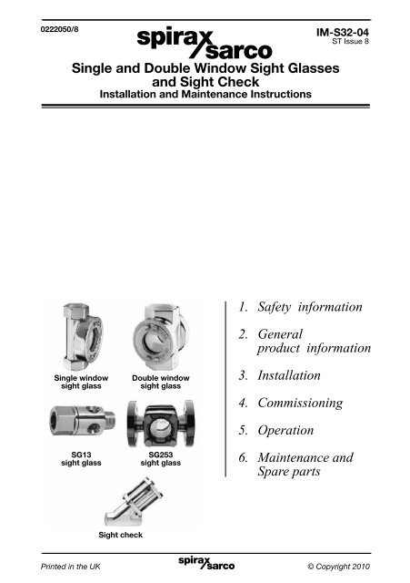
<strong>Single</strong> <strong>and</strong> <strong>Double</strong> <strong>Window</strong> <strong>Sight</strong> <strong>Glasses</strong><br />
<strong>and</strong> <strong>Sight</strong> Check<br />
Installation <strong>and</strong> Maintenance Instructions<br />
1. Safety information<br />
2. General<br />
product information<br />
<strong>Single</strong> window<br />
sight glass<br />
SG13<br />
sight glass<br />
<strong>Double</strong> window<br />
sight glass<br />
SG253<br />
sight glass<br />
3. Installation<br />
4. Commissioning<br />
5. Operation<br />
6. Maintenance <strong>and</strong><br />
Spare parts<br />
<strong>Sight</strong> check<br />
Printed IM-S32-04 in the ST UK Issue 8 © Copyright 20101
2<br />
IM-S32-04 ST Issue 8
1. Safety information<br />
Safe operation of these products can only be guaranteed if they are properly<br />
installed, commissioned, used <strong>and</strong> maintained by qualified personnel (see<br />
Section 1.11) in compliance with the operating instructions. General installation <strong>and</strong><br />
safety instructions for pipeline <strong>and</strong> plant construction, as well as the proper use<br />
of tools <strong>and</strong> safety equipment must also be complied with.<br />
Warning<br />
The gaskets used in these units (with exception to the SG13) contain thin stainless steel<br />
support rings which may cause physical injury if not h<strong>and</strong>led <strong>and</strong> disposed of carefully.<br />
Under certain conditions corrosive elements in condensate can affect the inside face of<br />
the sight tube / window, particularly where caustic alkali <strong>and</strong> hydrofluoric acid are present.<br />
It is recommended that the sight glass / sight check is periodically checked for thinning<br />
of the sight tube / window. If there is evidence of thinning or erosion damage then the<br />
sight tube / window should be replaced immediately. Always wear eye protection<br />
when viewing the contents of the sight glass / sight check.<br />
Reasonable steps should be taken to protect personnel from injury in the unlikely<br />
event that the sight tube / window breaks.<br />
1.1 Intended use<br />
Referring to the Installation <strong>and</strong> Maintenance Instructions, name-plate <strong>and</strong> Technical<br />
Information Sheet, check that the product is suitable for the intended use / application.<br />
The products listed below comply with the requirements of the European Pressure<br />
Equipment Directive 97 / 23 / EC <strong>and</strong> carry the mark when so required. It should be<br />
noted that products rated as 'SEP' are required by the Directive not to carry the<br />
mark. The products fall within the following Pressure Equipment Directive categories:<br />
Product<br />
Group 1 Group 2 Group 1 Group 2<br />
Gases Gases Liquids Liquids<br />
<strong>Single</strong> window sight glass DN10 - DN25 - SEP - SEP<br />
<strong>Double</strong> window sight glass DN15 - DN50 - SEP - SEP<br />
SG253 sight glass<br />
DN15 - DN40 - SEP - SEP<br />
DN50 - 1 - SEP<br />
SG13 sight glass DN15 - DN25 - SEP - SEP<br />
<strong>Spirax</strong> Hills sight check DN15 - DN25 - SEP - SEP<br />
i) These products have been specifically designed for use on steam, air or<br />
water / condensate which are in Group 2 of the above mentioned Pressure<br />
Equipment Directive. The products’ use on other fluids may be possible but, if this<br />
is contemplated, <strong>Spirax</strong> <strong>Sarco</strong> should be contacted to confirm the suitability of the<br />
product for the application being considered.<br />
ii) Check material suitability, pressure <strong>and</strong> temperature <strong>and</strong> their maximum <strong>and</strong><br />
minimum values. If the maximum operating limits of the product are lower than<br />
those of the system in which it is being fitted, or if malfunction of the product<br />
could result in a dangerous overpressure or overtemperature occurrence, ensure<br />
a safety device is included in the system to prevent such over-limit situations.<br />
iii) Determine the correct installation situation <strong>and</strong> direction of fluid flow.<br />
IM-S32-04 ST Issue 8 3
iv) <strong>Spirax</strong> <strong>Sarco</strong> products are not intended to withst<strong>and</strong> external stresses that may<br />
be induced by any system to which they are fitted. It is the responsibility of the<br />
installer to consider these stresses <strong>and</strong> take adequate precautions to minimise<br />
them.<br />
v) Remove protection covers from all connections <strong>and</strong> protective film from all<br />
name-plates, where appropriate, before installation on steam or other high<br />
temperature applications.<br />
1.2 Access<br />
Ensure safe access <strong>and</strong> if necessary a safe working platform (suitably guarded)<br />
before attempting to work on the product. Arrange suitable lifting gear if required.<br />
1.3 Lighting<br />
Ensure adequate lighting, particularly where detailed or intricate work is required.<br />
1.4 Hazardous liquids or gases in the pipeline<br />
Consider what is in the pipeline or what may have been in the pipeline at some<br />
previous time. Consider: flammable materials, substances hazardous to health,<br />
extremes of temperature.<br />
1.5 Hazardous environment around the product<br />
Consider: explosion risk areas, lack of oxygen (e.g. tanks, pits), dangerous gases,<br />
extremes of temperature, hot surfaces, fire hazard (e.g. during welding), excessive<br />
noise, moving machinery.<br />
1.6 Isolation<br />
Consider the effect on the complete system of the work proposed. Will any proposed<br />
action (e.g. closing isolation valves, electrical isolation) put any other part of the<br />
system or any personnel at risk?<br />
Dangers might include isolation of vents or protective devices or the rendering<br />
ineffective of controls or alarms. Ensure isolation valves are turned on <strong>and</strong> off in a<br />
gradual way to avoid system shocks.<br />
1.7 Pressure<br />
Before attempting any maintenance consider what is or may have been in the<br />
pipeline. Ensure that any pressure is isolated <strong>and</strong> safely vented to atmospheric<br />
pressure before attempting to maintain the product, this is easily achieved by<br />
fitting <strong>Spirax</strong> <strong>Sarco</strong> depressurisation valves type DV (see separate literature for<br />
details) <strong>and</strong> consider double isolation (double block <strong>and</strong> bleed) <strong>and</strong> the locking or<br />
labelling of closed valves. Do not assume that the system is depressurised even<br />
when a pressure gauge indicates zero.<br />
4<br />
IM-S32-04 ST Issue 8
1.8 Temperature<br />
Allow time for temperature to normalise after isolation to avoid the danger of<br />
burns <strong>and</strong> consider whether protective clothing (including safety glasses) is<br />
required.<br />
PTFE (SG13 - sight tube gasket):<br />
If parts made from PTFE have been subjected to a temperature approaching<br />
260°C (500°F) or higher, they will give off toxic fumes, which if inhaled are likely to<br />
cause temporary discomfort. It is essential for a no smoking rule to be enforced in<br />
all areas where PTFE is stored, h<strong>and</strong>led or processed as persons inhaling the<br />
fumes from burning tobacco contaminated with PTFE particles can develop<br />
'polymer fume fever'.<br />
1.9 Tools <strong>and</strong> consumables<br />
Before starting work ensure that you have suitable tools <strong>and</strong>/or consumables<br />
available. Use only genuine <strong>Spirax</strong> <strong>Sarco</strong> replacement parts.<br />
1.10 Protective clothing<br />
Consider whether you <strong>and</strong>/or others in the vicinity require any protective clothing<br />
to protect against the hazards of, for example, chemicals, high / low temperature,<br />
radiation, noise, falling objects, <strong>and</strong> dangers to eyes <strong>and</strong> face.<br />
1.11 Permits to work<br />
All work must be carried out or be supervised by a suitably competent person.<br />
Installation <strong>and</strong> operating personnel should be trained in the correct use of the<br />
product according to the Installation <strong>and</strong> Maintenance Instructions.<br />
Where a formal 'permit to work' system is in force it must be complied with. Where<br />
there is no such system, it is recommended that a responsible person should know<br />
what work is going on <strong>and</strong>, where necessary, arrange to have an assistant whose<br />
primary responsibility is safety.<br />
Post 'warning notices' if necessary.<br />
1.12 H<strong>and</strong>ling<br />
Manual h<strong>and</strong>ling of large <strong>and</strong>/or heavy products may present a risk of injury. Lifting,<br />
pushing, pulling, carrying or supporting a load by bodily force can cause injury<br />
particularly to the back. You are advised to assess the risks taking into account the<br />
task, the individual, the load <strong>and</strong> the working environment <strong>and</strong> use the appropriate<br />
h<strong>and</strong>ling method depending on the circumstances of the work being done.<br />
IM-S32-04 ST Issue 8 5
1.13 Residual hazards<br />
In normal use the external surface of the product may be very hot. If used at the<br />
maximum permitted operating conditions the surface temperature of some products<br />
may reach temperatures of 100°C (212°F).<br />
Many products are not self-draining. Take due care when dismantling or removing<br />
the product from an installation (refer to 'Maintenance instructions').<br />
1.14 Freezing<br />
Provision must be made to protect products which are not self-draining against<br />
frost damage in environments where they may be exposed to temperatures below<br />
freezing point.<br />
1.15 Disposal<br />
Unless otherwise stated in the Installation <strong>and</strong> Maintenance Instructions, these<br />
products are recyclable <strong>and</strong> no ecological hazard is anticipated with their disposal<br />
providing due care is taken, except:<br />
PTFE (SG13 - sight tube gasket):<br />
- Waste parts can only be disposed of by approved methods, not incineration.<br />
- Keep PTFE waste in a separate container, do not mix it with other rubbish, <strong>and</strong><br />
consign it to a l<strong>and</strong>fill site.<br />
1.16 Returning products<br />
Customers <strong>and</strong> stockists are reminded that under EC Health, Safety <strong>and</strong><br />
Environment Law, when returning products to <strong>Spirax</strong> <strong>Sarco</strong> they must provide<br />
information on any hazards <strong>and</strong> the precautions to be taken due to contamination<br />
residues or mechanical damage which may present a health, safety or<br />
environmental risk. This information must be provided in writing including<br />
Health <strong>and</strong> Safety data sheets relating to any substances identified as hazardous<br />
or potentially hazardous.<br />
6<br />
IM-S32-04 ST Issue 8
2. General product information<br />
2.1 <strong>Single</strong> window <strong>and</strong> double window sight glasses<br />
General description<br />
A range of single <strong>and</strong> double window sight glasses having screwed connections available in<br />
either brass or bronze depending on size.<br />
Note: For additional information see the following Technical Information Sheet TI-P022-05.<br />
Fig. 1<br />
<strong>Single</strong> window sight glass<br />
Fig. 2<br />
<strong>Double</strong> window sight glass<br />
Sizes <strong>and</strong> pipe connections<br />
<strong>Single</strong> window ", ½", ¾" <strong>and</strong> 1" screwed BSP or NPT<br />
<strong>Double</strong> window<br />
Temperature °C<br />
Pressure psi g<br />
0 10 20 30 40 50 60 70<br />
148<br />
100<br />
50<br />
½", ¾", 1" 1½" <strong>and</strong> 2" screwed BSP or NPT<br />
Pressure / temperature limits<br />
Steam<br />
saturation<br />
curve<br />
0<br />
0 1 2 3 4 5<br />
Pressure bar g<br />
The product must not be used in this region.<br />
Body design conditions<br />
PN5<br />
PMA Maximum allowable pressure 5 bar g @ 90°C (72.5 psi g @ 194°F)<br />
TMA Maximum allowable temperature 148°C @ 3.5 bar g (298.4°F @ 50.75 psi g)<br />
Minimum allowable temperature -29°C (-20.2°F)<br />
PMO<br />
Maximum operating pressure<br />
for saturated steam service<br />
3.5 bar g (50.75 psi g)<br />
TMO Maximum operating temperature 148°C @ 3.5 bar g (298.4°F @ 50.75 psi g)<br />
Minimum operating temperature 0°C (32°F)<br />
Note: For lower temperatures consult <strong>Spirax</strong> <strong>Sarco</strong>.<br />
Designed for a maximum cold hydraulic test pressure of: 7 bar g (101.5 psi g)<br />
PTMX Maximum test pressure (steam service) 3.5 bar g (50.75 psi g)<br />
300<br />
200<br />
100<br />
Temperature °F<br />
IM-S32-04 ST Issue 8 7
2.2 SG13 sight glass<br />
General description<br />
The SG13 is a maintainable brass multi-window sight glass with a cylindrical viewing window<br />
<strong>and</strong> screwed connections. The sight glass monitors the discharge downstream of steam traps<br />
in pressurised condensate return lines. It is screwed directly into the steam trap providing a<br />
modular monitoring system, thus eliminating the need for a connecting nipple, minimising joints<br />
<strong>and</strong> potential leak paths.<br />
The sight glass can also be installed in process lines to provide a visual indication of flow.<br />
Note: For additional information see the following Technical Information Sheet TI-P130-11.<br />
Fig. 3<br />
SG13 sight glass<br />
Sizes <strong>and</strong> pipe connections<br />
½", ¾" <strong>and</strong> 1" screwed BSP male taper/female parallel to BS 21 or<br />
½", ¾" <strong>and</strong> 1" screwed NPT male / female to ASME (ANSI) B 1.20.1.<br />
Pressure / temperature limits<br />
Temperature °C<br />
Pressure psi g<br />
0 50 100 150 200<br />
200<br />
150<br />
100<br />
50<br />
Steam<br />
saturation<br />
curve<br />
300<br />
200<br />
100<br />
Temperature °F<br />
0<br />
0 2 4 6 8 10 12 14 16<br />
Pressure bar g<br />
The product must not be used in this region.<br />
Body design conditions<br />
PN16<br />
PMA Maximum allowable pressure 16 bar g @ 130°C (232 psi g @ 266°F)<br />
TMA Maximum allowable temperature 200°C @ 13.5 bar g (392°F @ 195.8 psi g)<br />
Minimum allowable temperature -20°C (-4°F)<br />
PMO<br />
Maximum operating pressure<br />
for saturated steam service<br />
13 bar g (188.5 psi g)<br />
TMO Maximum operating temperature 200°C @ 13.5 bar g (392°F @ 195.8 psi g)<br />
Minimum operating temperature 0°C (32°F)<br />
Note: For lower temperatures consult <strong>Spirax</strong> <strong>Sarco</strong>.<br />
Designed for a maximum cold hydraulic test pressure of: 24 bar g (348 psi g)<br />
PTMX Maximum test pressure (steam service) 13 bar g (188.5 psi g)<br />
8<br />
IM-S32-04 ST Issue 8
2.3 SG253 sight glass<br />
General description<br />
The SG253 is an SG iron double window sight glass with flanged connections.<br />
Note: For additional information see the following Technical Information Sheet TI-P130-01.<br />
Fig. 4<br />
SG253 sight glass<br />
Sizes <strong>and</strong> pipe connections<br />
DN15, DN20, DN25, DN32, DN40 <strong>and</strong> DN50.<br />
Flanged EN 1092 PN25 <strong>and</strong> BS 1560 ASME (ANSI) B 1.20.1.<br />
Pressure / temperature limits<br />
Temperature °C<br />
Pressure psi g<br />
0 100 200 300<br />
280<br />
200<br />
A<br />
500<br />
400<br />
100<br />
300<br />
Steam<br />
saturation<br />
200<br />
0<br />
0<br />
curve<br />
C<br />
B 100<br />
5 10 15 20 25<br />
Pressure bar g<br />
The product must not be used in this region.<br />
A - B Flanged EN 1092 PN25. A - C Flanged BS 1560 ASME (ANSI) Class 150.<br />
Body design conditions PN25 <strong>and</strong> ASME (ANSI) 150<br />
PMA Maximum allowable PN25 25 bar g @ 100°C (362.5 psi g @ 212°F)<br />
pressure ASME 150 17.2 bar g @ 35°C (249.5 psi g @ 95°F)<br />
TMA Maximum PN25 280°C @ 18 bar g (536°F @ 261 psi g)<br />
allowable temperature ASME 150 280°C @ 10 bar g (536°F @ 145 psi g)<br />
Minimum allowable temperature -10°C (14°F)<br />
PMO Maximum operating pressure PN25 21 bar g (304.5 psi g)<br />
for saturated steam service ASME 150 13.8 bar g (200.1 psi g)<br />
TMO Maximum operating temperature 280°C @ 18 bar g (536°F @ 261 psi g)<br />
Minimum operating temperature 0°C (32°F)<br />
Note: For lower temperatures consult <strong>Spirax</strong> <strong>Sarco</strong>.<br />
Designed for a maximum PN25 38 bar g (551 psi g)<br />
cold hydraulic test pressure of: ASME 150 30 bar g (435 psi g)<br />
PTMX Maximum test pressure PN25 21 bar g (304.5 psi g)<br />
(steam service) ASME 150 13.8 bar g (200.1 psi g)<br />
Temperature °F<br />
IM-S32-04 ST Issue 8 9
2.4 <strong>Sight</strong> check<br />
General description<br />
A sight check is a combined sight glass <strong>and</strong> check valve. It is used to observe discharges from<br />
steam traps. The position of the ball check indicates whether or not condensate is flowing. Where<br />
condensate rises after the trap it eliminates the need for a separate check valve thus simplifying<br />
installation.<br />
It is particularly useful for commissioning steam traps fitted with a steam lock release (SLR) unit.<br />
It can also be used on other liquid lines where the materials of construction are compatible.<br />
Note: For additional information see the following Technical Information Sheet TI-P022-01.<br />
Fig. 5<br />
<strong>Sight</strong> check<br />
Sizes <strong>and</strong> pipe connections<br />
½", ¾" <strong>and</strong> 1" screwed BSP or NPT.<br />
Pressure / temperature limits<br />
Temperature °C<br />
Pressure psi g<br />
0<br />
148<br />
10 20 30 40 50<br />
100<br />
50<br />
250<br />
Steam<br />
saturation<br />
200<br />
curve<br />
150<br />
100<br />
0<br />
50<br />
0 1 2 3 3.5<br />
Pressure g bar<br />
The product must not be used in this region.<br />
Body design conditions<br />
PN3.6<br />
PMA Maximum allowable pressure 3.5 bar g @ 148°C (50.75 psi g @ 295.6°F)<br />
TMA Maximum allowable temperature 148°C @ 3.5 bar g (294.8°F 50.25 psi g)<br />
Minimum allowable temperature -10°C (14°F)<br />
PMO<br />
Maximum operating pressure<br />
for saturated steam service<br />
3.5 bar g (50.75 psi g)<br />
TMO Maximum operating temperature 148°C 3.5 bar g (295.6°F @ 50.75 psi g)<br />
Minimum operating temperature 0°C (32°F)<br />
Note: For lower temperatures consult <strong>Spirax</strong> <strong>Sarco</strong>.<br />
Designed for a maximum cold hydraulic test pressure of: 7 bar g (101.5 psi g)<br />
PTMX Maxiumum test pressure (steam service) 3.5 bar g (50.75 psi g)<br />
Temperature °F<br />
10<br />
IM-S32-04 ST Issue 8
3. Installation<br />
Note:<br />
Before actioning any installation observe the 'Safety information' in Section 1.<br />
Warning<br />
Under certain conditions corrosive elements in condensate can affect the inside face<br />
of the sight tube / window, particularly where caustic alkali <strong>and</strong> hydrofluoric acid are<br />
present. It is recommended that the sight glass / sight check is periodically checked for<br />
thinning of the sight tube / window. If there is evidence of thinning or erosion damage<br />
then the sight tube / window should be replaced immediately. Always wear eye<br />
protection when viewing the contents of the sight glass / sight check.<br />
Reasonable steps should be taken to protect personnel from injury in the unlikely<br />
event that the sight tube / window breaks.<br />
<strong>Sight</strong> glasses <strong>and</strong> sight checks can be fitted in either a horizontal or vertical line (flow upwards<br />
only for sight check) on the outlet side of a steam trap. Where the trap is a blast discharge<br />
type e.g. thermodynamic, the sight glass <strong>and</strong> sight check must be fitted at least 1 m (3 ft) from<br />
the trap. This is to ensure that the glass is not subjected to thermal shock or pressure.<br />
Reasonable steps should be taken to protect personnel from injury in the unlikely event that<br />
the glass breaks.<br />
Ensure access is available for maintenance purposes.<br />
4. Commissioning<br />
After installation or maintenance ensure that the system is fully functional. Carry out tests on<br />
any alarms or protective devices.<br />
5. Operation<br />
5.1 <strong>Sight</strong> glasses<br />
The sight glass has a smooth concentric reduction in the inlet connection which promotes<br />
turbulence in the sight glass when the fluid is passing through it. The turbulent flow inside the<br />
sight glass permits any fluid to be detected.<br />
<strong>Sight</strong> glasses can be used to detect blocked valves, strainers, steam traps <strong>and</strong> other pipeline<br />
equipment. <strong>Sight</strong> glasses can also be used for inspection purposes, i.e. to compare the colour<br />
of the fluid at different stages of the process, enabling adjustments to be made quickly <strong>and</strong><br />
effectively.<br />
The SG13 cylinder view can be screwed directly into the steam trap it is monitoring to form a<br />
modular steam trap arrangement.<br />
5.2 <strong>Sight</strong> checks<br />
The sight check is a sight glass <strong>and</strong> check valve combination in one unit. A ball in the top of<br />
the flow tube is lifted off its seat by the fluid as it flows through the cylindrical window to the<br />
outlet connection. The ball movement makes the flow easy to see yet provides shut-off on<br />
reverse flow.<br />
IM-S32-04 ST Issue 8 11
6. Maintenance <strong>and</strong> Spare parts<br />
6.1 <strong>Single</strong> window <strong>and</strong> double window sight glasses<br />
Note:<br />
Before actioning any maintenance programme observe the 'Safety information' in<br />
Section 1.<br />
How to renew the window(s) <strong>and</strong> gaskets:<br />
- Isolate the sight glass <strong>and</strong> allow the pressure <strong>and</strong> temperature to reduce to ambient<br />
conditions.<br />
- After isolation unscrew the bezel(s) (2) <strong>and</strong> remove old gaskets (4 <strong>and</strong> 5) <strong>and</strong> window(s) (3).<br />
- Carefully clean the recess.<br />
- Refit new gaskets <strong>and</strong> window(s), ensuring that a gasket (4) is fitted to either side of<br />
each window (3).<br />
- Replace the bezel(s) <strong>and</strong> tighten to the recommended torque (see Table 1).<br />
- After maintenance has been completed, isolation valves should opened slowly to allow<br />
pressure <strong>and</strong> temperature to build up in a controlled manner.<br />
- Check for leaks.<br />
6.2 Spare parts (for the single window <strong>and</strong> double window sight glasses)<br />
The spare parts available are shown in solid outline. Parts drawn in broken line are not<br />
supplied as spares.<br />
Available spares<br />
Set of windows <strong>and</strong> gaskets 3, 4, 5<br />
Set of gaskets 4, 5<br />
How to order spares<br />
Always order spares by using the description given in the column headed 'Available spares'<br />
<strong>and</strong> state the size <strong>and</strong> type of sight glass.<br />
Example: 1 off Set of windows <strong>and</strong> gaskets for a <strong>Spirax</strong> <strong>Sarco</strong> 1" double window sight glass.<br />
12<br />
IM-S32-04 ST Issue 8
Fig. 6<br />
<strong>Single</strong> window<br />
sight glass<br />
Fig. 7<br />
<strong>Double</strong> window<br />
sight glass<br />
2<br />
4<br />
3<br />
5<br />
5<br />
3<br />
4<br />
2<br />
Table 1 Recommended tightening torque<br />
Item No.<br />
Part<br />
or<br />
mm<br />
N m<br />
(lbf ft)<br />
2 Bezel 60 - 65 (43 - 47)<br />
IM-S32-04 ST Issue 8 13
6.3 SG253 sight glass<br />
Note:<br />
Before actioning any maintenance programme observe the 'Safety information' in<br />
Section 1.<br />
How to renew the windows <strong>and</strong> gaskets:<br />
- Isolate the sight glass <strong>and</strong> allow the pressure <strong>and</strong> temperature to reduce to ambient<br />
conditions.<br />
- After isolation unscrew the cover bolts (5) <strong>and</strong> remove the old gaskets (4) <strong>and</strong> windows (3).<br />
- Carefully clean the recess.<br />
- Refit new gaskets <strong>and</strong> windows, ensuring that a gasket (4) is fitted to either side of<br />
each window (3).<br />
- Replace the covers (2) <strong>and</strong> cover bolts (5) <strong>and</strong> tighten to the recommended torque (see<br />
Table 2).<br />
- After maintenance has been completed, isolation valves should opened slowly to allow<br />
pressure <strong>and</strong> temperature to build up in a controlled manner.<br />
- Check for leaks.<br />
6.4 Spare parts (for the SG253 sight glass)<br />
The spare parts available are shown in solid outline. Parts drawn in broken line are not<br />
supplied as spares.<br />
Available spares<br />
Set of windows <strong>and</strong> gaskets 3, 4<br />
Please note: For the DN25 <strong>and</strong> DN32 sizes a set of bolts (16 A/F M10 x 40) is also included<br />
due to the increased thickness of the glass.<br />
Set of gaskets 4<br />
How to order spares<br />
Always order spares by using the description given in the column headed 'Available spares'<br />
<strong>and</strong> state the size <strong>and</strong> type of the sight glass.<br />
Example: 1 off Set of windows <strong>and</strong> gaskets for a <strong>Spirax</strong> <strong>Sarco</strong> DN15 SG253 sight glass.<br />
14<br />
IM-S32-04 ST Issue 8
Fig. 8<br />
SG253 sight glass<br />
5<br />
(not an available spare)<br />
2<br />
4<br />
3<br />
4<br />
4<br />
3<br />
4<br />
2<br />
5<br />
(not an available spare)<br />
Recommended tightening torques<br />
or<br />
Item Part<br />
mm<br />
N m (lbf ft)<br />
DN15 - DN20 17 A / F M10 x 30 12 (8.6)<br />
Pre 08-2010: 17 A / F M10 x 35<br />
5 DN25 - DN32<br />
28 (20.6)<br />
Post 08-2010: 16 A / F M10 x 40<br />
DN40 - DN50 19 A / F M12 x 40 38 (28.0)<br />
IM-S32-04 ST Issue 8 15
6.5 SG13 sight glass<br />
Note:<br />
Before actioning any maintenance programme observe the 'Safety information' in<br />
Section 1.<br />
How to renew the sight tube <strong>and</strong> gaskets:<br />
- Isolate the sight glass <strong>and</strong> allow the pressure <strong>and</strong> temperature to reduce to ambient<br />
conditions.<br />
- After isolation remove the SG13 sight glass from the pipeline.<br />
- Unscrew the end connection from the body (2) <strong>and</strong> remove the sight tube (4).<br />
- Take out the old gaskets (3) taking care not to damage the seating face <strong>and</strong> carefully clean<br />
out the recesses.<br />
- Fit the new gaskets (3) supplied with sight tube (4) (see Section 6.6, Spare parts).<br />
- Ensure the sight tube (4) is aligned correctly within the body. Then tighten the end<br />
connection (2) to the recommended torque (see Table 3). Note: Misalignment of the sight<br />
tube (4) within the body may cause the edge of the glass to fracture.<br />
- Refit the sight glass into the pipeline.<br />
- After maintenance has been completed, isolation valves should opened slowly to allow<br />
pressure <strong>and</strong> temperature to build up in a controlled manner.<br />
- Check for leaks.<br />
6.6 Spare parts (for the SG13 sight glass)<br />
The spare parts available are shown in solid outline. Parts drawn in broken line are not<br />
supplied as spares.<br />
Available spare<br />
<strong>Sight</strong> glass assembly 3 (2 off), 4<br />
How to order spares<br />
Always order spares by using the description given in the column headed 'Available spare'.<br />
Since the sight glass assembly is the same for all three sizes, it will always be:-<br />
Example: 1 off <strong>Sight</strong> glass assembly for a <strong>Spirax</strong> <strong>Sarco</strong> SG13 sight glass.<br />
16<br />
IM-S32-04 ST Issue 8
Fig. 9<br />
SG13 sight glass<br />
3 4 3 2<br />
Table 3 Recommended tightening torques<br />
Item No.<br />
Part<br />
or<br />
mm<br />
N m<br />
(lbf ft)<br />
½" - DN15 32 A/F 35 - 40 (25 - 29)<br />
2 ¾" - DN20 36 A/F 35 - 40 (25 - 29)<br />
1" - DN25 46 A/F 35 - 40 (25 - 29)<br />
IM-S32-04 ST Issue 8 17
6.7 <strong>Sight</strong> check<br />
Note:<br />
Before actioning any maintenance programme observe the 'Safety information' in<br />
Section 1.<br />
How to renew the sight tube:<br />
- Isolate the sight check <strong>and</strong> allow the pressure <strong>and</strong> temperature to reduce to ambient<br />
conditions.<br />
- After isolation remove the bolt <strong>and</strong> washers (7 <strong>and</strong> 8).<br />
- Remove the cover (6).<br />
- Take out the old gaskets (2) <strong>and</strong> the sight tube (3) <strong>and</strong> carefully clean out the recesses.<br />
- Fit the new gaskets (2) supplied with sight tube (3) <strong>and</strong> reassemble. Tighten the bolts<br />
evenly to the recommended torque, ensuring the ends of the sight tube are centralised<br />
on the gaskets (see Table 4).<br />
- It is advisable to do up the bolts little more than finger tight, retightening as necessary<br />
after a period of use to the recommended tightening torque (see Table 4).<br />
- After maintenance has been completed, isolation valves should opened slowly to allow<br />
pressure <strong>and</strong> temperature to build up in a controlled manner.<br />
- Check for leaks.<br />
How to renew the discharge tube:<br />
- Remove the cover (6) <strong>and</strong> the sight tube (3) the same way as 'To renew sight tube' above,<br />
<strong>and</strong> lift out the ball check (5).<br />
- Using the notches, carefully unscrew the old discharge tube (4) <strong>and</strong> fit a new one.<br />
- Renew the gaskets (2), fit a new ball check (5) <strong>and</strong> reassemble. Tighten the bolts evenly<br />
to the recommended torque, ensuring the ends of the sight tube are centralised on the<br />
gaskets (see Table 4).<br />
- After maintenance has been completed, isolation valves should opened slowly to allow<br />
pressure <strong>and</strong> temperature to build up in a controlled manner.<br />
- Check for leaks.<br />
18<br />
IM-S32-04 ST Issue 8
6.8 Spare parts (for the sight check)<br />
The spare parts available are shown in solid outline. Parts drawn in broken line are not<br />
supplied as spares.<br />
Available spares<br />
<strong>Sight</strong> tube assembly<br />
2 (2 off), 3 (1 off)<br />
Discharge tube assembly (set of 2) 4, 5<br />
Set of bolts <strong>and</strong> washers (set of 4*) 7, 8<br />
Gasket set (packet of 6†) 2<br />
Available spares are common to ½" <strong>and</strong> ¾" sizes, but not 1".<br />
Note:<br />
* Earlier models used studs, nuts <strong>and</strong> washers <strong>and</strong> these are contained in the set of bolts pack.<br />
† Earlier models used ethylene propylene gaskets which were considerably thicker than<br />
graphite laminate.<br />
How to order spares<br />
Always order spares by using the description given in the column headed 'Available spares'<br />
<strong>and</strong> state the size of the sight check.<br />
Example: 1 off <strong>Sight</strong> tube assembly for a <strong>Spirax</strong> <strong>Sarco</strong> ½" sight check.<br />
6<br />
8 7<br />
<strong>Sight</strong> tube assembly<br />
2<br />
3<br />
2<br />
Fig. 10<br />
<strong>Sight</strong> check<br />
Discharge<br />
tube assembly<br />
4<br />
5<br />
Table 4 Recommended tightening torques<br />
Item No.<br />
Part<br />
or<br />
mm<br />
N m<br />
(lbf ft)<br />
7 ½", ¾" <strong>and</strong> 1" 10 A/F M6 x 65 1.8 - 2.2 (1.3 - 1.6)<br />
½" <strong>and</strong> ¼" 9<br />
/16" x 26 BSW 5 - 6 (3.6 - 4.3)<br />
4<br />
1" 7<br />
/8" x 20 UNF 5 - 6 (3.6 - 4.3)<br />
IM-S32-04 ST Issue 8 19
20<br />
IM-S32-04 ST Issue 8