
You also want an ePaper? Increase the reach of your titles
YUMPU automatically turns print PDFs into web optimized ePapers that Google loves.
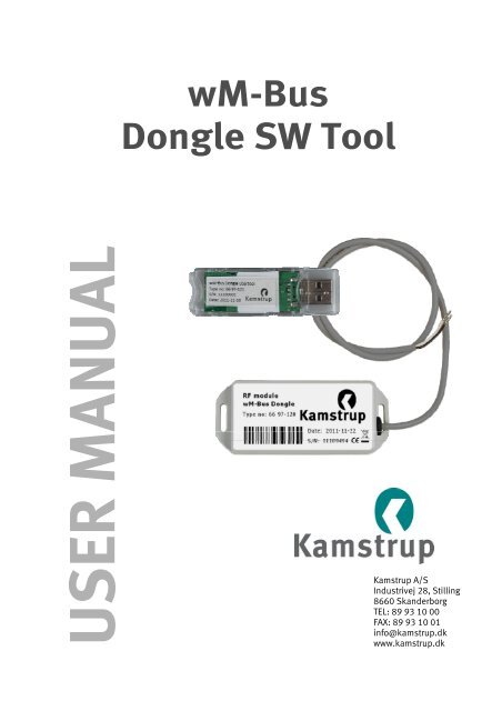
<strong>wM</strong>-<strong>Bus</strong><br />
<strong>Dongle</strong> <strong>SW</strong> <strong>Tool</strong><br />
USER MANUAL<br />
<strong>Kamstrup</strong> A/S<br />
Industrivej 28, Stilling<br />
8660 Skanderborg<br />
TEL: 89 93 10 00<br />
FAX: 89 93 10 01<br />
info@kamstrup.dk<br />
www.kamstrup.dk
User xxx manual<br />
<strong>wM</strong>-<strong>Bus</strong> <strong>Dongle</strong> <strong>SW</strong> <strong>Tool</strong><br />
Contents<br />
1 Overview ................................................................................................................................ 1<br />
1.1 Terms and definitions .................................................................................................... 2<br />
1.2 References ..................................................................................................................... 2<br />
2 Installation ............................................................................................................................. 3<br />
3 Configuration ......................................................................................................................... 4<br />
3.1 Main tab ........................................................................................................................ 4<br />
3.2 Meter x tabs .................................................................................................................. 6<br />
3.3 <strong>Dongle</strong> tab (normally not used for this application) ........................................................ 7<br />
3.4 Trace tab ........................................................................................................................ 8<br />
4 Software upgrade dongle ........................................................................................................ 9<br />
5 Help menu ............................................................................................................................ 10<br />
Appendix A: DSMR set-up .......................................................................................................... 11<br />
Appendix B: OMS T1 meter set-up ............................................................................................. 12<br />
Appendix C: Flonidan Rev. B meter set-up .................................................................................. 13<br />
Appendix D: Hydrometer set-up ................................................................................................. 14<br />
Appendix E: OMS T2 meter set-up ............................................................................................. 16<br />
Appendix F: DSMR TimeDate format F set-up ............................................................................. 17<br />
5512-1057 GB / 12.2011 / A1<br />
i
User manual<br />
<strong>wM</strong>-<strong>Bus</strong> <strong>Dongle</strong> <strong>SW</strong> <strong>Tool</strong><br />
1 Overview<br />
This document describes how to use the <strong>Kamstrup</strong> <strong>wM</strong>-<strong>Bus</strong> <strong>Dongle</strong> <strong>SW</strong> <strong>Tool</strong> to set up a <strong>wM</strong>-<strong>Bus</strong><br />
dongle to communicate with a wireless M-<strong>Bus</strong> meter. The meter can be a <strong>Kamstrup</strong> heat or water<br />
meter or other wireless M-<strong>Bus</strong> meters using C-mode communication.<br />
5512-1057 GB / 12.2011 / A1<br />
Figure 1<br />
This <strong>Tool</strong> is used for setting up the parameters in the dongle to enable it to communicate with the<br />
selected meter devices. The <strong>Tool</strong> communicates with the <strong>wM</strong>-<strong>Bus</strong> dongle either through wired<br />
connection or wirelessly through a <strong>Kamstrup</strong> <strong>wM</strong>-<strong>Bus</strong> <strong>Dongle</strong> USB <strong>Tool</strong> connected to a PC.<br />
1
User manual<br />
<strong>wM</strong>-<strong>Bus</strong> <strong>Dongle</strong> <strong>SW</strong> <strong>Tool</strong><br />
1.1 Terms and definitions<br />
CAS<br />
Central Access Server (Back office)<br />
<strong>Dongle</strong><br />
<strong>wM</strong>-<strong>Bus</strong><br />
DSMR<br />
OMS<br />
<strong>wM</strong>-<strong>Bus</strong> <strong>Dongle</strong><br />
<strong>wM</strong>-<strong>Bus</strong> <strong>Dongle</strong> USB <strong>Tool</strong><br />
<strong>wM</strong>-<strong>Bus</strong> <strong>Dongle</strong> <strong>SW</strong> <strong>Tool</strong><br />
In meter reading applications, a dongle is a piece of hardware that<br />
converts wired M-<strong>Bus</strong> signals from a computer to <strong>wM</strong>-<strong>Bus</strong> in the air<br />
for connecting to meter devices.<br />
Wireless M-<strong>Bus</strong> according to standard EN13757-4<br />
Dutch Smart Meter Requirement<br />
Open Metering System<br />
Hereafter named <strong>Dongle</strong><br />
Hereafter named USB <strong>Tool</strong><br />
Hereafter named Software <strong>Tool</strong><br />
1.2 References<br />
EN13757-3 Communication systems for meters and remote reading of meters - Part 3:<br />
Dedicated application layer.<br />
EN13757-4<br />
FIPS-197<br />
DSMR<br />
Communication systems for meters and remote reading of meters - Part 4: Wireless<br />
meter readout (Radio meter reading for operation in the 868 MHz to 870 MHz SRD<br />
band).<br />
Federal Information Processing Standard. ADVANCED ENCRYPTION STANDARD (AES)<br />
published by the National Institute of Standards and Technology (NIST), USA.<br />
“Dutch Smart Meter Requirements v2.2 final Main.pdf”<br />
“Dutch Smart Meter Requirements v2.2 final P2.pdf”<br />
“Dutch Smart Meter Requirements v2.2 final Tender.pdf”.<br />
5512-1057 GB / 12.2011 / A1<br />
2
User manual<br />
<strong>wM</strong>-<strong>Bus</strong> <strong>Dongle</strong> <strong>SW</strong> <strong>Tool</strong><br />
2 Installation<br />
Install the <strong>Kamstrup</strong> <strong>wM</strong>-<strong>Bus</strong> <strong>Dongle</strong> <strong>SW</strong> <strong>Tool</strong> on each PC that will be used to communicate with the<br />
<strong>Dongle</strong>.<br />
Download the software from www.kamstrup.com, and install it on your PC. When the installation is<br />
completed, a <strong>Kamstrup</strong> icon used for starting the software tool is generated and placed under start<br />
All programs.<br />
5512-1057 GB / 12.2011 / A1<br />
3
User manual<br />
<strong>wM</strong>-<strong>Bus</strong> <strong>Dongle</strong> <strong>SW</strong> <strong>Tool</strong><br />
3 Configuration<br />
To configure the <strong>Dongle</strong>, follow the steps below.<br />
Connect the <strong>Dongle</strong> to a supply, either a wired bus or to 24 V DC, run the <strong>wM</strong>-<strong>Bus</strong> application,<br />
and click the [Run the WIRELESS Application] button (see Figure 2)<br />
Search for <strong>wM</strong>-<strong>Bus</strong> meters (see Figure 2)<br />
Choose the <strong>wM</strong>-<strong>Bus</strong> meters (see Figure 2)<br />
Configure the wired M-<strong>Bus</strong> address etc. (see Figure 3)<br />
Store the configuration (see Figure 3).<br />
Note: In Figures 2 and 3, all fields marked with red must be filled in.<br />
The menu tabs of the software are described in the following paragraphs.<br />
3.1 Main tab<br />
5512-1057 GB / 12.2011 / A1<br />
Figure 2<br />
Choose application: Select the interface to use, wired or wireless. If wired application is used,<br />
remember to connect an M-<strong>Bus</strong> to the serial/USB converter, e.g. a <strong>Kamstrup</strong> MBM 250D. If the<br />
wireless application is used, remember to connect the USB <strong>Tool</strong> to the PC. Drivers for this USB <strong>Tool</strong><br />
are normally found by the operating system.<br />
4
User manual<br />
<strong>wM</strong>-<strong>Bus</strong> <strong>Dongle</strong> <strong>SW</strong> <strong>Tool</strong><br />
Login: Not in use for this application.<br />
WIRELESS: Address selection: Click the [Find boards in range] button to start searching for nearby<br />
dongles. Select the dongle you want to configure, and click [Select board].<br />
WIRED: Communication settings: Select the COM port from the COM port drop-down menu. Click the<br />
[Connect] button. The status of the COM port is shown in the bottom line of the window, and if the<br />
status is OK, it will say “Connected to serial”. The bottom line in the window will show the status of<br />
the serial port. The program automatically scans for active COM ports at start-up and only shows the<br />
active COM ports. Click the [Search COM] button to carry out a new search.<br />
Search for <strong>wM</strong>-<strong>Bus</strong> meters:<br />
Actions: Click the [Get Statistics] button to get information about the last 10 radio communications<br />
received by the <strong>Dongle</strong>.<br />
Realtime <strong>Dongle</strong> Data:<br />
Timestamp: Timestamp set by the <strong>Dongle</strong> when the data is seen (not used for this application).<br />
C-field: Specifies the frame type according to EN13757-4.<br />
Manufacturer: The unique User/Manufacturer ID of the meter.<br />
Id No: The unique serial number of the meter.<br />
Ver: The version of the meter.<br />
Media: The device type information, HEAT, WATER etc.<br />
RSSI: “Received Signal Strength Indicator” is indicated in dBm. Minimum level is -95 dBm.<br />
Click the [Get Statistics] again until you find a meter (serial number) that you want to connect to the<br />
<strong>Dongle</strong>.<br />
Select <strong>wM</strong>-<strong>Bus</strong> meter:<br />
In the column Id No., select the meter serial number that you want to connect to the dongle, and<br />
click [Transfer to] to copy the meter details to a specific Meter tab (1-4). Select the tab in question<br />
for further configuration.<br />
5512-1057 GB / 12.2011 / A1<br />
5
User manual<br />
<strong>wM</strong>-<strong>Bus</strong> <strong>Dongle</strong> <strong>SW</strong> <strong>Tool</strong><br />
3.2 Meter x tabs<br />
This description is valid for the tabs Meter 1, Meter 2, Meter 3 and Meter 4.<br />
5512-1057 GB / 12.2011 / A1<br />
Figure 3<br />
Choose option by function: Select <strong>Kamstrup</strong> C-mode in the drop-down menu.<br />
Meter install state: Set this parameter to 1<br />
Meter M-<strong>Bus</strong> Address: Select the primary M-<strong>Bus</strong> address (from 1 to 250), e.g. the last two digits of<br />
the meter’s serial number (the dongle supports secondary addressing)<br />
T1 period (in seconds): Enter a timeout in seconds. When the connection between the dongle and<br />
the meter is lost and after entering the timeout, the answer from the dongle is an “empty response”<br />
KEY: Enter the key and click [Get key from file] to get the encryption key from the encryption file (use<br />
the customer number as password)<br />
[Set Meter 1 Settings]: Click this button to save the settings.<br />
6
User manual<br />
<strong>wM</strong>-<strong>Bus</strong> <strong>Dongle</strong> <strong>SW</strong> <strong>Tool</strong><br />
The dongle can also be used for non-<strong>Kamstrup</strong> meters. See appendices for alternative configuration<br />
possibilities. Note that <strong>Kamstrup</strong> does not offer support if the dongle is used for non-<strong>Kamstrup</strong><br />
meters.<br />
3.3 <strong>Dongle</strong> tab (normally not used for this application)<br />
5512-1057 GB / 12.2011 / A1<br />
Figure 4<br />
[Get <strong>Dongle</strong> Settings]: Click this button to read the <strong>Dongle</strong> set-up data and display it in this window.<br />
OPTIONS:<br />
M-<strong>Bus</strong> enabled: Tick this checkbox for enabling wired M-<strong>Bus</strong><br />
Radio enabled: Tick this checkbox for enabling set-up via wireless M-<strong>Bus</strong><br />
Encryption M-<strong>Bus</strong>: Tick this checkbox for enabling encryption via the wired M-<strong>Bus</strong><br />
Spare bit 3: Not used<br />
Spare bit 4: Not used<br />
Spare bit 5: Not used<br />
Spare bit 6: Not used<br />
<strong>Dongle</strong> initiated: Untick this checkbox, and click the [Set <strong>Dongle</strong> Settings] button under Actions to<br />
reset all data in the <strong>Dongle</strong> to factory defaults. Click the button again for new use.<br />
<strong>Dongle</strong> AES key: Not used for this application.<br />
7
User manual<br />
<strong>wM</strong>-<strong>Bus</strong> <strong>Dongle</strong> <strong>SW</strong> <strong>Tool</strong><br />
[Send AES to USB stick]: Not used for this application.<br />
[Set <strong>Dongle</strong> Settings]: Click this button to save the new <strong>Dongle</strong> data selected in the above fields.<br />
Under DONGLE ADDRESS, only the ID No. can be set, the other fields are fixed in the <strong>Dongle</strong>.<br />
[Remove <strong>Dongle</strong> Encryption]: If encrypted M-<strong>Bus</strong> is enabled, click this button to remove the<br />
encrypted M-<strong>Bus</strong>. The option Encrypted M-<strong>Bus</strong> must stay enabled when clicking [Remove <strong>Dongle</strong><br />
Encryption] and is automatically cleared afterwards.<br />
[Get<strong>Dongle</strong>Ver]: Click this button to get the <strong>Dongle</strong> version.<br />
3.4 Trace tab<br />
Data sent and received can be viewed in this window for debugging purposes.<br />
5512-1057 GB / 12.2011 / A1<br />
8
User manual<br />
<strong>wM</strong>-<strong>Bus</strong> <strong>Dongle</strong> <strong>SW</strong> <strong>Tool</strong><br />
4 Software upgrade dongle<br />
In the File menu, choose <strong>Dongle</strong> Update.<br />
Figure 5<br />
Click the [UPGRADE] button, and choose the *.bin file for the <strong>Dongle</strong> in the File menu. The upgrade<br />
starts automatically, when selected.<br />
Figure 6<br />
Do not stop the upgrade, when started. The upgrade only takes a few minutes.<br />
When the upgrade is finished, click [Close] to close the Upgrade <strong>Dongle</strong> software dialog box.<br />
5512-1057 GB / 12.2011 / A1<br />
9
User manual<br />
<strong>wM</strong>-<strong>Bus</strong> <strong>Dongle</strong> <strong>SW</strong> <strong>Tool</strong><br />
5 Help menu<br />
Click the [Help] button in the upper right corner or press Ctrl+A to open the dialog box <strong>wM</strong>-<strong>Bus</strong><br />
<strong>Dongle</strong> <strong>SW</strong> <strong>Tool</strong>. Here, the version of the program is shown, and if the USB <strong>Tool</strong> has been opened,<br />
the version of this software is shown too.<br />
Figure 7<br />
5512-1057 GB / 12.2011 / A1<br />
10
User manual<br />
<strong>wM</strong>-<strong>Bus</strong> <strong>Dongle</strong> <strong>SW</strong> <strong>Tool</strong><br />
Appendix A: DSMR set-up<br />
5512-1057 GB / 12.2011 / A1<br />
Set-up of a DSMR meter:<br />
Figure 8<br />
• After starting the meter, find the meter in the Main tab, and transfer the data to the wanted<br />
Meter X tab, or enter the meter data manually.<br />
• Set the OPTIONS to 0x07 0x0F, depending on whether the wired M-BUS should be encrypted or<br />
not.<br />
• Set Meter install state to 255. Next time the meter sends out an ACCESS DEMAND INSTALL STATE<br />
(CI=0x06), the <strong>Dongle</strong> will acknowledge this, and the state will change to 1 when seeing the<br />
next message from the meter.<br />
• Set Meter M-<strong>Bus</strong> address to where you want the meter to respond on the M-<strong>Bus</strong>.<br />
• Rev B barcode is not used.<br />
11
User manual<br />
<strong>wM</strong>-<strong>Bus</strong> <strong>Dongle</strong> <strong>SW</strong> <strong>Tool</strong><br />
Appendix B: OMS T1 meter set-up<br />
5512-1057 GB / 12.2011 / A1<br />
Figure 9<br />
If the option board (radio module) in the meter is an OMS T1 type, the set-up should be as follows:<br />
• Transfer the data from the Main tab, or enter the METER ADDRESS manually.<br />
• Set the options as shown, i.e. tick the checkboxes Meter enabled and Meter data valid (Options<br />
in HEX = 49).<br />
• Set Meter install state to 1 as there is no installation procedure.<br />
• T1 period (in seconds) and T2 fraction cannot be set.<br />
• Set IEK and KEY to the same transport key.<br />
• Rev B barcode is not used.<br />
• The Option Board data fields are not used.<br />
No Encryption on M-<strong>Bus</strong>:<br />
• Untick this checkbox if the decryption has to be done in the back office (then the Options in HEX<br />
will show 41).<br />
Important for OMS: Both IEK and KEY must be set, and set to the same key.<br />
12
User manual<br />
<strong>wM</strong>-<strong>Bus</strong> <strong>Dongle</strong> <strong>SW</strong> <strong>Tool</strong><br />
Appendix C: Flonidan Rev. B meter set-up<br />
5512-1057 GB / 12.2011 / A1<br />
Figure 10<br />
If the option board (radio module) in the meter is an old Flonidan Revision B type, the set-up should<br />
be as follows:<br />
• Transfer the data from the Main tab, or enter the METER ADDRESS manually.<br />
• Set the options as shown, i.e. tick the checkboxes Meter enabled, 2-way radio, Rev B<br />
compatible and Meter data valid (Options in hex = 23).<br />
• If the meter is not installed, set the Meter Install state to 255. Next time the meter sends out an<br />
ACCESS DEMAND INSTALL STATE (Ci=0x06), the <strong>Dongle</strong> will acknowledge this, and the state will<br />
change to 1 when seeing the next message from the meter.<br />
• Set Meter M-<strong>Bus</strong> address to where you want the meter to respond on the M-<strong>Bus</strong>.<br />
• T1 period and T2 fraction cannot be set.<br />
• IEK and KEY are not used.<br />
• Set the Rev B barcode. As this is not included in the radio message, the <strong>Dongle</strong> will add this to<br />
the wired M-BUS REQ_UD2 response.<br />
• The Option Board data fields are not used.<br />
13
User manual<br />
<strong>wM</strong>-<strong>Bus</strong> <strong>Dongle</strong> <strong>SW</strong> <strong>Tool</strong><br />
Appendix D: Hydrometer set-up<br />
5512-1057 GB / 12.2011 / A1<br />
Set-up of a Hydrometer meter:<br />
Figure 11<br />
• Find the meter on the Main tab, and transfer the data to the relevant Meter X tab.<br />
• Set Meter install state to 1 as there is no installation procedure for Hydrometer.<br />
• Set Meter M-BUS address to where you want the meter to respond on the M-<strong>Bus</strong>.<br />
• T1, T2, IEK, KEY, Rev B barcode and the Option Board data fields are not used.<br />
Warning: If [Get Meter X Settings] is clicked, do not click [Set Meter X Settings] as this will destroy<br />
the meter settings (Hydrometer addressing is proprietary, and setting the address after getting the<br />
meter settings will result in a wrong address).<br />
14
User manual<br />
<strong>wM</strong>-<strong>Bus</strong> <strong>Dongle</strong> <strong>SW</strong> <strong>Tool</strong><br />
In <strong>wM</strong>-<strong>Bus</strong> <strong>Dongle</strong> Software <strong>Tool</strong> version 2.6, tick the checkbox Cnv HYD in the lower right corner,<br />
and the program will treat the HYD, EWT and GWF manufacturers in a special way as they are sent as<br />
M-<strong>Bus</strong> signals and not proprietary. The ID No., Ver and Media will be shown correctly. The data can<br />
be transferred to the Meter 1-4 tabs, and the buttons [Set Meter X Settings] and [Get Meter X<br />
Settings] can be used without problems.<br />
5512-1057 GB / 12.2011 / A1<br />
Figure 12<br />
15
User manual<br />
<strong>wM</strong>-<strong>Bus</strong> <strong>Dongle</strong> <strong>SW</strong> <strong>Tool</strong><br />
Appendix E: OMS T2 meter set-up<br />
5512-1057 GB / 12.2011 / A1<br />
Figure 13<br />
If the option board (radio module) in the meter is an OMS T2 type, the set-up should be as follows:<br />
• Transfer the data from the Main tab, or enter the METER ADDRESS manually.<br />
• Set the options as shown, i.e. tick the checkboxes Meter enabled, 2-way radio, OMS T2 protocol<br />
and Meter data valid (Options in hex = 4B).<br />
• Set Meter install state to 1 as there is no installation procedure.<br />
• Set T1 period (in seconds) to how often the meter is to send out meter data. T2 fraction is not<br />
used.<br />
• Enter the same key in IEK and KEY.<br />
• Rev B barcode is not used.<br />
• For the Option Board data fields, see 3.2 Meter x tabs.<br />
No Encryption on M-<strong>Bus</strong>:<br />
• Tick this checkbox if the decryption has to be done in the back office (then the Options in HEX<br />
will show 43).<br />
Important for OMS: Both IEK and KEY must be set, and set to the same key.<br />
16
User manual<br />
<strong>wM</strong>-<strong>Bus</strong> <strong>Dongle</strong> <strong>SW</strong> <strong>Tool</strong><br />
Appendix F: DSMR TimeDate format F set-up<br />
5512-1057 GB / 12.2011 / A1<br />
Figure 14<br />
If TimeDate format F is required to and from the <strong>Dongle</strong>, set up the <strong>Dongle</strong> as shown in Appendix A:<br />
DSMR set-up. However, always run unencrypted M-<strong>Bus</strong>, i.e. tick the checkbox No Encryption on M-<br />
<strong>Bus</strong>, and tick the checkbox TimeDate format F (Options in HEX = 2F).<br />
17