SC48 Guide - Digidesign
SC48 Guide - Digidesign
SC48 Guide - Digidesign

You also want an ePaper? Increase the reach of your titles
YUMPU automatically turns print PDFs into web optimized ePapers that Google loves.
VENUE <strong>SC48</strong> <strong>Guide</strong><br />
and Software Version 2.8 for VENUE <strong>SC48</strong> Systems<br />
<strong>Digidesign</strong><br />
2001 Junipero Serra Boulevard<br />
Daly City, CA 94014-3886 USA<br />
tel: 650·731·6300<br />
fax: 650·731·6399<br />
Technical Support (USA)<br />
tel: 650·731·6100<br />
fax: 650·731·6375<br />
Product Information (USA)<br />
tel: 650·731·6102<br />
tel: 800·333·2137<br />
International Offices<br />
Visit the <strong>Digidesign</strong> website<br />
for contact information<br />
Website<br />
www.digidesign.com<br />
<strong>Guide</strong> Part Number: 9322-61189-00 REV A 04/09
Legal Notices<br />
This guide is copyrighted ©2009 by <strong>Digidesign</strong>, a division of Avid Technology, Inc.<br />
(hereafter “<strong>Digidesign</strong>”), with all rights reserved. Under copyright laws, this guide<br />
may not be duplicated in whole or in part without the written consent of<br />
<strong>Digidesign</strong>.<br />
003, 003 Rack, 96 I/O, 96i I/O, 192 Digital I/O, 192 I/O, 888|24 I/O, 882|20<br />
I/O, 1622 I/O, 24-Bit ADAT Bridge I/O, AudioSuite, Avid, Avid DNA, Avid Mojo,<br />
Avid Unity, Avid Unity ISIS, Avid Unity MediaNetwork, Avid Xpress, AVoption,<br />
AVoption|V10, Beat Detective, Bruno, C|24, Command|8, Control|24,<br />
D-Command, D-Control, D-Fi, D-fx, D-Show, DAE, Digi 002, Digi 002 Rack,<br />
DigiBase, DigiDelivery, <strong>Digidesign</strong>, <strong>Digidesign</strong> Audio Engine, <strong>Digidesign</strong><br />
Intelligent Noise Reduction, <strong>Digidesign</strong> TDM Bus, DigiDrive, DigiRack, DigiTest,<br />
DigiTranslator, DINR, DV Toolkit, EditPack, Eleven, Impact, Interplay, M-Audio,<br />
MachineControl, Maxim, Mbox, MediaComposer, MIDI I/O, MIX, MultiShell, OMF,<br />
OMF Interchange, PRE, ProControl, Pro Tools M-Powered, Pro Tools,<br />
Pro Tools|HD, Pro Tools LE, QuickPunch, Reel Tape, Reso, Reverb One, ReVibe,<br />
RM1, RM2, RTAS, Smack!, SoundReplacer, Sound Designer II, Strike, Structure,<br />
SYNC HD, SYNC I/O, Synchronic, TL Space, Velvet, X-Form, and Xpand! are<br />
trademarks or registered trademarks of <strong>Digidesign</strong> and/or Avid Technology, Inc.<br />
All other trademarks are the property of their respective owners.<br />
Product features, specifications, system requirements, and availability are<br />
subject to change without notice.<br />
<strong>Guide</strong> Part Number: 9322-61189-00 REV A 04/09<br />
Comments or suggestions regarding our documentation?<br />
email: techpubs@digidesign.com<br />
Communications & Safety Regulation Information<br />
Compliance Statement<br />
The model VENUE <strong>SC48</strong> complies with the following standards regulating<br />
interference and EMC:<br />
• FCC Part 15 Class B<br />
• EN55103-1 E3<br />
• EN55103-2 E3<br />
• AS/NZS 3548 Class B<br />
• CISPR 22 Class B<br />
Radio and Television Interference<br />
This equipment has been tested and found to comply with the limits for a Class<br />
B digital device, pursuant to Part 15 of the FCC Rules.<br />
DECLARATION OF CONFORMITY<br />
We, <strong>Digidesign</strong>, 2001 Junipero Serra Boulevard<br />
Daly City, CA 94014-3886, USA<br />
650-731-6300<br />
declare under our sole responsibility that the product<br />
VENUE <strong>SC48</strong><br />
complies with Part 15 of FCC Rules.<br />
Operation is subject to the following two conditions: (1) this device may not<br />
cause harmful interference, and (2) this device must accept any interference<br />
received, including interference that may cause undesired operation.<br />
Communication Statement<br />
NOTE: This equipment has been tested and found to comply with the limits for a<br />
Class B digital device, pursuant to Part 15 of the FCC Rules. These limits are<br />
designed to provide reasonable protection against harmful interference in a<br />
residential installation. This equipment generates, uses, and can radiate radio<br />
frequency energy and, if not installed and used in accordance with the<br />
instructions, may cause harmful interference to radio communications. However,<br />
there is no guarantee that interference will not occur in a particular installation.<br />
If this equipment does cause harmful interference to radio or television<br />
reception, which can be determined by turning the equipment off and on, the user<br />
is encouraged to try and correct the interference by one or more of the following<br />
measures:<br />
• Reorient or locate the receiving antenna.<br />
• Increase the separation between the equipment and receiver.<br />
• Connect the equipment into an outlet on a circuit different from that to which<br />
the receiver is connected.<br />
• Consult the dealer or an experienced radio/TV technician for help.<br />
Any modifications to the unit, unless expressly approved by <strong>Digidesign</strong>, could<br />
void the user's authority to operate the equipment.<br />
Canadian Compliance Statement:<br />
This Class B digital apparatus complies with Canadian ICES-003<br />
Cet appareil numérique de la classe B est conforme à la norme NMB-003 du<br />
Canada<br />
Australian Compliance<br />
CE Compliance Statement:<br />
<strong>Digidesign</strong> is authorized to apply the CE (Conformité Europénne) mark on this<br />
compliant equipment thereby declaring conformity to EMC Directive<br />
89/336/EEC and Low Voltage Directive 73/23/EEC.<br />
Input Rating<br />
I/P: 100-120V~/220-240V~, 50/60 Hz, 200W
Safety Statement<br />
This equipment has been tested to comply with USA and Canadian safety<br />
certification in accordance with the specifications of UL Standards: UL60065 7th<br />
/IEC 60065 7th and Canadian CAN/CSA C22.2 60065:03. <strong>Digidesign</strong> Inc., has<br />
been authorized to apply the appropriate UL & CUL mark on its compliant<br />
equipment.<br />
Warning<br />
Important Safety Instructions<br />
1) Read these instructions.<br />
2) Keep these instructions.<br />
3) Heed all warnings.<br />
4) Follow all instructions.<br />
5) Do not use this equipment near water.<br />
6) Clean only with dry cloth.<br />
7) Do not block any ventilation openings. Install in accordance with the<br />
manufacturer’s instructions.<br />
8) Do not install near any heat sources such as radiators, heat registers, stoves,<br />
or other equipment (including amplifiers) that produce heat.<br />
9) Do not defeat the safety purpose of the polarized or grounding-type plug. A<br />
polarized plug has two blades with one wider than the other. A grounding type<br />
plug has two blades and a third grounding prong. The wide blade or the third<br />
prong are provided for your safety. If the provided plug does not fit into your<br />
outlet, consult an electrician for replacement of the obsolete outlet.<br />
10) Protect power cords from being walked on or pinched particularly at plugs,<br />
convenience receptacles, and the point where they exit from the equipment.<br />
11) Only use attachments/accessories specified by the manufacturer.<br />
12) Use only with a cart, stand, tripod, bracket, or table specified by the<br />
manufacturer, or sold with the equipment. When a cart is used, use caution when<br />
moving the cart/equipment combination to avoid injury from tip-over.<br />
13) Unplug this equipment during lightning storms or when unused for long<br />
periods of time.<br />
14) Refer all servicing to qualified service personnel. Servicing is required when<br />
the equipment has been damaged in any way, such as power-supply cord or plug<br />
is damaged, liquid has been spilled or objects have fallen into the equipment,<br />
the equipment has been exposed to rain or moisture, does not operate normally,<br />
or has been dropped.<br />
15) The equipment shall not be exposed to dripping or splashing and no objects<br />
filled with liquids (such as vases) shall be placed on the equipment.<br />
Warning! To reduce the risk of fire or electric shock, do not expose this<br />
equipment to rain or moisture.<br />
16) The equipment should be connected to a properly-grounded (earthed)<br />
receptacle.<br />
17) The main power switch is located on the back panel of the VENUE <strong>SC48</strong>. It<br />
should remain accessible after installation.<br />
18) The mains plug is used as the disconnecting device and shall remain readily<br />
operable.<br />
19) The equipment shall be used at a maximum ambient temperature of 40° C.<br />
20) CAUTION! Danger of explosion if battery is incorrectly replaced.<br />
Replace only with the same or equivalent type.
Contents<br />
Part I<br />
Overview and Installation<br />
Chapter 1. Introduction to VENUE <strong>SC48</strong> . . . . . . . . . . . . . . . . . . . . . . . . . . . . . . . . . . . . . . . . . . . . . . . . . . . . . . . . . . . . 3<br />
VENUE <strong>SC48</strong> Features . . . . . . . . . . . . . . . . . . . . . . . . . . . . . . . . . . . . . . . . . . . . . . . . . . . . . . . . . . . . . . . . . . . . . . . . . . 3<br />
System Components . . . . . . . . . . . . . . . . . . . . . . . . . . . . . . . . . . . . . . . . . . . . . . . . . . . . . . . . . . . . . . . . . . . . . . . . . . . 4<br />
VENUE <strong>SC48</strong> Expansion Options . . . . . . . . . . . . . . . . . . . . . . . . . . . . . . . . . . . . . . . . . . . . . . . . . . . . . . . . . . . . . . . . . . . 5<br />
Operational Requirements . . . . . . . . . . . . . . . . . . . . . . . . . . . . . . . . . . . . . . . . . . . . . . . . . . . . . . . . . . . . . . . . . . . . . . . 5<br />
Connection Requirements . . . . . . . . . . . . . . . . . . . . . . . . . . . . . . . . . . . . . . . . . . . . . . . . . . . . . . . . . . . . . . . . . . . . . . . 5<br />
Chapter 2. Configuring and Connecting <strong>SC48</strong> . . . . . . . . . . . . . . . . . . . . . . . . . . . . . . . . . . . . . . . . . . . . . . . . . . . . . . . 7<br />
Unpacking and Assembling the Console . . . . . . . . . . . . . . . . . . . . . . . . . . . . . . . . . . . . . . . . . . . . . . . . . . . . . . . . . . . . . 7<br />
Connecting the VENUE <strong>SC48</strong> . . . . . . . . . . . . . . . . . . . . . . . . . . . . . . . . . . . . . . . . . . . . . . . . . . . . . . . . . . . . . . . . . . . . . 9<br />
Connecting AC Power . . . . . . . . . . . . . . . . . . . . . . . . . . . . . . . . . . . . . . . . . . . . . . . . . . . . . . . . . . . . . . . . . . . . . . . . . . 9<br />
Connecting a VGA or DVI Display . . . . . . . . . . . . . . . . . . . . . . . . . . . . . . . . . . . . . . . . . . . . . . . . . . . . . . . . . . . . . . . . . . 9<br />
Connecting USB Keyboard and Mouse . . . . . . . . . . . . . . . . . . . . . . . . . . . . . . . . . . . . . . . . . . . . . . . . . . . . . . . . . . . . . . . 9<br />
Connecting Audio . . . . . . . . . . . . . . . . . . . . . . . . . . . . . . . . . . . . . . . . . . . . . . . . . . . . . . . . . . . . . . . . . . . . . . . . . . . . 10<br />
Connecting Synchronization, Control, and Lights. . . . . . . . . . . . . . . . . . . . . . . . . . . . . . . . . . . . . . . . . . . . . . . . . . . . . . . 11<br />
Powering Up the System . . . . . . . . . . . . . . . . . . . . . . . . . . . . . . . . . . . . . . . . . . . . . . . . . . . . . . . . . . . . . . . . . . . . . . . 13<br />
Setting the System Clock . . . . . . . . . . . . . . . . . . . . . . . . . . . . . . . . . . . . . . . . . . . . . . . . . . . . . . . . . . . . . . . . . . . . . . . 13<br />
Installing Other Optional Software. . . . . . . . . . . . . . . . . . . . . . . . . . . . . . . . . . . . . . . . . . . . . . . . . . . . . . . . . . . . . . . . . 13<br />
About Digital Input and Sample Rate Conversion . . . . . . . . . . . . . . . . . . . . . . . . . . . . . . . . . . . . . . . . . . . . . . . . . . . . . . 13<br />
Part II<br />
System Description<br />
Chapter 3. VENUE <strong>SC48</strong> Control Overview . . . . . . . . . . . . . . . . . . . . . . . . . . . . . . . . . . . . . . . . . . . . . . . . . . . . . . . . . 17<br />
VENUE <strong>SC48</strong> Top Panel . . . . . . . . . . . . . . . . . . . . . . . . . . . . . . . . . . . . . . . . . . . . . . . . . . . . . . . . . . . . . . . . . . . . . . . . 17<br />
Input Channels and Faders. . . . . . . . . . . . . . . . . . . . . . . . . . . . . . . . . . . . . . . . . . . . . . . . . . . . . . . . . . . . . . . . . . . . . . 18<br />
Selected Channel Sections (ACS) . . . . . . . . . . . . . . . . . . . . . . . . . . . . . . . . . . . . . . . . . . . . . . . . . . . . . . . . . . . . . . . . . 22<br />
Flex Channel. . . . . . . . . . . . . . . . . . . . . . . . . . . . . . . . . . . . . . . . . . . . . . . . . . . . . . . . . . . . . . . . . . . . . . . . . . . . . . . . 23<br />
Output Masters . . . . . . . . . . . . . . . . . . . . . . . . . . . . . . . . . . . . . . . . . . . . . . . . . . . . . . . . . . . . . . . . . . . . . . . . . . . . . . 24<br />
Master and Global Controls . . . . . . . . . . . . . . . . . . . . . . . . . . . . . . . . . . . . . . . . . . . . . . . . . . . . . . . . . . . . . . . . . . . . . 25<br />
Chapter 4. Basic Commands and Modes . . . . . . . . . . . . . . . . . . . . . . . . . . . . . . . . . . . . . . . . . . . . . . . . . . . . . . . . . . . 27<br />
Control Overview . . . . . . . . . . . . . . . . . . . . . . . . . . . . . . . . . . . . . . . . . . . . . . . . . . . . . . . . . . . . . . . . . . . . . . . . . . . . . 27<br />
Config Mode and Show Mode . . . . . . . . . . . . . . . . . . . . . . . . . . . . . . . . . . . . . . . . . . . . . . . . . . . . . . . . . . . . . . . . . . . . 28<br />
System Lock. . . . . . . . . . . . . . . . . . . . . . . . . . . . . . . . . . . . . . . . . . . . . . . . . . . . . . . . . . . . . . . . . . . . . . . . . . . . . . . . 28<br />
Global Modifier Switches . . . . . . . . . . . . . . . . . . . . . . . . . . . . . . . . . . . . . . . . . . . . . . . . . . . . . . . . . . . . . . . . . . . . . . . 29<br />
Software Screen Pages and Tabs . . . . . . . . . . . . . . . . . . . . . . . . . . . . . . . . . . . . . . . . . . . . . . . . . . . . . . . . . . . . . . . . . 30<br />
Contents v
Chapter 5. Navigating and Selecting Channels . . . . . . . . . . . . . . . . . . . . . . . . . . . . . . . . . . . . . . . . . . . . . . . . . . . . . . 33<br />
Banking Input Channels and FX Returns . . . . . . . . . . . . . . . . . . . . . . . . . . . . . . . . . . . . . . . . . . . . . . . . . . . . . . . . . . . . . 33<br />
Banking the Output Section. . . . . . . . . . . . . . . . . . . . . . . . . . . . . . . . . . . . . . . . . . . . . . . . . . . . . . . . . . . . . . . . . . . . . . 36<br />
Selecting and Targeting Channels . . . . . . . . . . . . . . . . . . . . . . . . . . . . . . . . . . . . . . . . . . . . . . . . . . . . . . . . . . . . . . . . . 36<br />
Targeting Plug-In Inserts . . . . . . . . . . . . . . . . . . . . . . . . . . . . . . . . . . . . . . . . . . . . . . . . . . . . . . . . . . . . . . . . . . . . . . . . 37<br />
Screen Controls . . . . . . . . . . . . . . . . . . . . . . . . . . . . . . . . . . . . . . . . . . . . . . . . . . . . . . . . . . . . . . . . . . . . . . . . . . . . . . 38<br />
Screen Shortcuts . . . . . . . . . . . . . . . . . . . . . . . . . . . . . . . . . . . . . . . . . . . . . . . . . . . . . . . . . . . . . . . . . . . . . . . . . . . . . 39<br />
Input Channel Presets. . . . . . . . . . . . . . . . . . . . . . . . . . . . . . . . . . . . . . . . . . . . . . . . . . . . . . . . . . . . . . . . . . . . . . . . . . 42<br />
Chapter 6. Channel Control . . . . . . . . . . . . . . . . . . . . . . . . . . . . . . . . . . . . . . . . . . . . . . . . . . . . . . . . . . . . . . . . . . . . . . . 45<br />
Using Channel Control. . . . . . . . . . . . . . . . . . . . . . . . . . . . . . . . . . . . . . . . . . . . . . . . . . . . . . . . . . . . . . . . . . . . . . . . . . 45<br />
Functions. . . . . . . . . . . . . . . . . . . . . . . . . . . . . . . . . . . . . . . . . . . . . . . . . . . . . . . . . . . . . . . . . . . . . . . . . . . . . . . . . . . 46<br />
User Assignment . . . . . . . . . . . . . . . . . . . . . . . . . . . . . . . . . . . . . . . . . . . . . . . . . . . . . . . . . . . . . . . . . . . . . . . . . . . . . 48<br />
Availability of Channel Control Functions . . . . . . . . . . . . . . . . . . . . . . . . . . . . . . . . . . . . . . . . . . . . . . . . . . . . . . . . . . . . 49<br />
Chapter 7. Options . . . . . . . . . . . . . . . . . . . . . . . . . . . . . . . . . . . . . . . . . . . . . . . . . . . . . . . . . . . . . . . . . . . . . . . . . . . . . . . 51<br />
System . . . . . . . . . . . . . . . . . . . . . . . . . . . . . . . . . . . . . . . . . . . . . . . . . . . . . . . . . . . . . . . . . . . . . . . . . . . . . . . . . . . . 51<br />
Devices . . . . . . . . . . . . . . . . . . . . . . . . . . . . . . . . . . . . . . . . . . . . . . . . . . . . . . . . . . . . . . . . . . . . . . . . . . . . . . . . . . . . 53<br />
Other Options and Settings . . . . . . . . . . . . . . . . . . . . . . . . . . . . . . . . . . . . . . . . . . . . . . . . . . . . . . . . . . . . . . . . . . . . . . 53<br />
Part III<br />
Signal Routing<br />
Chapter 8. Inputs and Input Routing . . . . . . . . . . . . . . . . . . . . . . . . . . . . . . . . . . . . . . . . . . . . . . . . . . . . . . . . . . . . . . . 63<br />
Configuring Inputs . . . . . . . . . . . . . . . . . . . . . . . . . . . . . . . . . . . . . . . . . . . . . . . . . . . . . . . . . . . . . . . . . . . . . . . . . . . . 63<br />
Assigning Input Sources to Channels . . . . . . . . . . . . . . . . . . . . . . . . . . . . . . . . . . . . . . . . . . . . . . . . . . . . . . . . . . . . . . . 64<br />
Routing Input Channels. . . . . . . . . . . . . . . . . . . . . . . . . . . . . . . . . . . . . . . . . . . . . . . . . . . . . . . . . . . . . . . . . . . . . . . . . 65<br />
Using Built-In Dynamics and EQ . . . . . . . . . . . . . . . . . . . . . . . . . . . . . . . . . . . . . . . . . . . . . . . . . . . . . . . . . . . . . . . . . . . 67<br />
Using Inserts on Channels . . . . . . . . . . . . . . . . . . . . . . . . . . . . . . . . . . . . . . . . . . . . . . . . . . . . . . . . . . . . . . . . . . . . . . . 68<br />
Adjusting Input Controls . . . . . . . . . . . . . . . . . . . . . . . . . . . . . . . . . . . . . . . . . . . . . . . . . . . . . . . . . . . . . . . . . . . . . . . . 68<br />
Flex Channel . . . . . . . . . . . . . . . . . . . . . . . . . . . . . . . . . . . . . . . . . . . . . . . . . . . . . . . . . . . . . . . . . . . . . . . . . . . . . . . . 71<br />
Using Input Direct. . . . . . . . . . . . . . . . . . . . . . . . . . . . . . . . . . . . . . . . . . . . . . . . . . . . . . . . . . . . . . . . . . . . . . . . . . . . . 72<br />
Chapter 9. Outputs and Output Routing . . . . . . . . . . . . . . . . . . . . . . . . . . . . . . . . . . . . . . . . . . . . . . . . . . . . . . . . . . . . 73<br />
Configuring Outputs . . . . . . . . . . . . . . . . . . . . . . . . . . . . . . . . . . . . . . . . . . . . . . . . . . . . . . . . . . . . . . . . . . . . . . . . . . . 73<br />
Assigning Busses to Hardware Outputs. . . . . . . . . . . . . . . . . . . . . . . . . . . . . . . . . . . . . . . . . . . . . . . . . . . . . . . . . . . . . . 74<br />
Routing Group Outputs to the Main Busses . . . . . . . . . . . . . . . . . . . . . . . . . . . . . . . . . . . . . . . . . . . . . . . . . . . . . . . . . . . 75<br />
Using Inserts on Output Busses . . . . . . . . . . . . . . . . . . . . . . . . . . . . . . . . . . . . . . . . . . . . . . . . . . . . . . . . . . . . . . . . . . . 75<br />
Adjusting Output Controls . . . . . . . . . . . . . . . . . . . . . . . . . . . . . . . . . . . . . . . . . . . . . . . . . . . . . . . . . . . . . . . . . . . . . . . 76<br />
Adjusting Main Bus Controls . . . . . . . . . . . . . . . . . . . . . . . . . . . . . . . . . . . . . . . . . . . . . . . . . . . . . . . . . . . . . . . . . . . . . 77<br />
Direct Outputs . . . . . . . . . . . . . . . . . . . . . . . . . . . . . . . . . . . . . . . . . . . . . . . . . . . . . . . . . . . . . . . . . . . . . . . . . . . . . . . 78<br />
Matrix Mixers . . . . . . . . . . . . . . . . . . . . . . . . . . . . . . . . . . . . . . . . . . . . . . . . . . . . . . . . . . . . . . . . . . . . . . . . . . . . . . . . 79<br />
Assigning and Using VCAs . . . . . . . . . . . . . . . . . . . . . . . . . . . . . . . . . . . . . . . . . . . . . . . . . . . . . . . . . . . . . . . . . . . . . . . 79<br />
vi<br />
VENUE <strong>SC48</strong> <strong>Guide</strong>
Chapter 10. Groups . . . . . . . . . . . . . . . . . . . . . . . . . . . . . . . . . . . . . . . . . . . . . . . . . . . . . . . . . . . . . . . . . . . . . . . . . . . . . . 81<br />
Configuring Group Busses . . . . . . . . . . . . . . . . . . . . . . . . . . . . . . . . . . . . . . . . . . . . . . . . . . . . . . . . . . . . . . . . . . . . . . 81<br />
Routing Inputs to Group Busses . . . . . . . . . . . . . . . . . . . . . . . . . . . . . . . . . . . . . . . . . . . . . . . . . . . . . . . . . . . . . . . . . . 81<br />
Routing Group Outputs to the Main Busses . . . . . . . . . . . . . . . . . . . . . . . . . . . . . . . . . . . . . . . . . . . . . . . . . . . . . . . . . . 81<br />
Managing Group Bus Assignments . . . . . . . . . . . . . . . . . . . . . . . . . . . . . . . . . . . . . . . . . . . . . . . . . . . . . . . . . . . . . . . . 82<br />
Group Bus Signal Flow Options . . . . . . . . . . . . . . . . . . . . . . . . . . . . . . . . . . . . . . . . . . . . . . . . . . . . . . . . . . . . . . . . . . . 84<br />
Adjusting Group Bus Output Controls. . . . . . . . . . . . . . . . . . . . . . . . . . . . . . . . . . . . . . . . . . . . . . . . . . . . . . . . . . . . . . . 84<br />
Simple and Expert Operational Modes. . . . . . . . . . . . . . . . . . . . . . . . . . . . . . . . . . . . . . . . . . . . . . . . . . . . . . . . . . . . . . 85<br />
Chapter 11. Aux Sends. . . . . . . . . . . . . . . . . . . . . . . . . . . . . . . . . . . . . . . . . . . . . . . . . . . . . . . . . . . . . . . . . . . . . . . . . . . 87<br />
Configuring Aux Busses . . . . . . . . . . . . . . . . . . . . . . . . . . . . . . . . . . . . . . . . . . . . . . . . . . . . . . . . . . . . . . . . . . . . . . . . 87<br />
Routing Inputs to Aux Busses . . . . . . . . . . . . . . . . . . . . . . . . . . . . . . . . . . . . . . . . . . . . . . . . . . . . . . . . . . . . . . . . . . . . 88<br />
Routing Aux Busses to Outputs and Plug-Ins . . . . . . . . . . . . . . . . . . . . . . . . . . . . . . . . . . . . . . . . . . . . . . . . . . . . . . . . . 89<br />
Adjusting Aux Send Controls. . . . . . . . . . . . . . . . . . . . . . . . . . . . . . . . . . . . . . . . . . . . . . . . . . . . . . . . . . . . . . . . . . . . . 90<br />
Managing Aux Bus Assignments . . . . . . . . . . . . . . . . . . . . . . . . . . . . . . . . . . . . . . . . . . . . . . . . . . . . . . . . . . . . . . . . . . 91<br />
Chapter 12. Matrix Mixers . . . . . . . . . . . . . . . . . . . . . . . . . . . . . . . . . . . . . . . . . . . . . . . . . . . . . . . . . . . . . . . . . . . . . . . 93<br />
Matrix Mixers . . . . . . . . . . . . . . . . . . . . . . . . . . . . . . . . . . . . . . . . . . . . . . . . . . . . . . . . . . . . . . . . . . . . . . . . . . . . . . . 93<br />
Configuring Matrix Mixers. . . . . . . . . . . . . . . . . . . . . . . . . . . . . . . . . . . . . . . . . . . . . . . . . . . . . . . . . . . . . . . . . . . . . . . 94<br />
Adjusting Matrix Mixer Input Controls . . . . . . . . . . . . . . . . . . . . . . . . . . . . . . . . . . . . . . . . . . . . . . . . . . . . . . . . . . . . . . 96<br />
Adjusting Matrix Mixer Output Controls . . . . . . . . . . . . . . . . . . . . . . . . . . . . . . . . . . . . . . . . . . . . . . . . . . . . . . . . . . . . . 98<br />
Snapshot Data and Parameters for Matrix Mixers. . . . . . . . . . . . . . . . . . . . . . . . . . . . . . . . . . . . . . . . . . . . . . . . . . . . . . 98<br />
Chapter 13. Patchbay . . . . . . . . . . . . . . . . . . . . . . . . . . . . . . . . . . . . . . . . . . . . . . . . . . . . . . . . . . . . . . . . . . . . . . . . . . . . 99<br />
Accessing the Patchbay . . . . . . . . . . . . . . . . . . . . . . . . . . . . . . . . . . . . . . . . . . . . . . . . . . . . . . . . . . . . . . . . . . . . . . . . 99<br />
Overview of the Patchbay. . . . . . . . . . . . . . . . . . . . . . . . . . . . . . . . . . . . . . . . . . . . . . . . . . . . . . . . . . . . . . . . . . . . . . . 99<br />
Navigating the Patchbay . . . . . . . . . . . . . . . . . . . . . . . . . . . . . . . . . . . . . . . . . . . . . . . . . . . . . . . . . . . . . . . . . . . . . . 101<br />
Routing Channels in the Patchbay . . . . . . . . . . . . . . . . . . . . . . . . . . . . . . . . . . . . . . . . . . . . . . . . . . . . . . . . . . . . . . . 102<br />
Warning when Stealing Inputs or Outputs in the Patchbay. . . . . . . . . . . . . . . . . . . . . . . . . . . . . . . . . . . . . . . . . . . . . . . 103<br />
VENUE System Information Export . . . . . . . . . . . . . . . . . . . . . . . . . . . . . . . . . . . . . . . . . . . . . . . . . . . . . . . . . . . . . . . 104<br />
Patch List Export . . . . . . . . . . . . . . . . . . . . . . . . . . . . . . . . . . . . . . . . . . . . . . . . . . . . . . . . . . . . . . . . . . . . . . . . . . . . 105<br />
Chapter 14. Metering . . . . . . . . . . . . . . . . . . . . . . . . . . . . . . . . . . . . . . . . . . . . . . . . . . . . . . . . . . . . . . . . . . . . . . . . . . . 107<br />
Channel Meters. . . . . . . . . . . . . . . . . . . . . . . . . . . . . . . . . . . . . . . . . . . . . . . . . . . . . . . . . . . . . . . . . . . . . . . . . . . . . 107<br />
ACS Input and Dynamics Meters. . . . . . . . . . . . . . . . . . . . . . . . . . . . . . . . . . . . . . . . . . . . . . . . . . . . . . . . . . . . . . . . . 108<br />
Metering Section. . . . . . . . . . . . . . . . . . . . . . . . . . . . . . . . . . . . . . . . . . . . . . . . . . . . . . . . . . . . . . . . . . . . . . . . . . . . 109<br />
Metering Options. . . . . . . . . . . . . . . . . . . . . . . . . . . . . . . . . . . . . . . . . . . . . . . . . . . . . . . . . . . . . . . . . . . . . . . . . . . . 110<br />
Chapter 15. Solo and Monitor Busses . . . . . . . . . . . . . . . . . . . . . . . . . . . . . . . . . . . . . . . . . . . . . . . . . . . . . . . . . . . . 111<br />
Solo Bus Modes . . . . . . . . . . . . . . . . . . . . . . . . . . . . . . . . . . . . . . . . . . . . . . . . . . . . . . . . . . . . . . . . . . . . . . . . . . . . 111<br />
Selecting a Solo Mode . . . . . . . . . . . . . . . . . . . . . . . . . . . . . . . . . . . . . . . . . . . . . . . . . . . . . . . . . . . . . . . . . . . . . . . . 111<br />
Solo Operation Options . . . . . . . . . . . . . . . . . . . . . . . . . . . . . . . . . . . . . . . . . . . . . . . . . . . . . . . . . . . . . . . . . . . . . . . 112<br />
Solo Bus Operation . . . . . . . . . . . . . . . . . . . . . . . . . . . . . . . . . . . . . . . . . . . . . . . . . . . . . . . . . . . . . . . . . . . . . . . . . . 113<br />
Soloing Single Channels. . . . . . . . . . . . . . . . . . . . . . . . . . . . . . . . . . . . . . . . . . . . . . . . . . . . . . . . . . . . . . . . . . . . . . . 113<br />
Solo Safing Channels. . . . . . . . . . . . . . . . . . . . . . . . . . . . . . . . . . . . . . . . . . . . . . . . . . . . . . . . . . . . . . . . . . . . . . . . . 114<br />
Monitor Bus Operation. . . . . . . . . . . . . . . . . . . . . . . . . . . . . . . . . . . . . . . . . . . . . . . . . . . . . . . . . . . . . . . . . . . . . . . . 114<br />
Talkback, 2-Track and Oscillator Controls . . . . . . . . . . . . . . . . . . . . . . . . . . . . . . . . . . . . . . . . . . . . . . . . . . . . . . . . . . 116<br />
Contents<br />
vii
Chapter 16. Muting and Mute Groups . . . . . . . . . . . . . . . . . . . . . . . . . . . . . . . . . . . . . . . . . . . . . . . . . . . . . . . . . . . . . 119<br />
Muting . . . . . . . . . . . . . . . . . . . . . . . . . . . . . . . . . . . . . . . . . . . . . . . . . . . . . . . . . . . . . . . . . . . . . . . . . . . . . . . . . . . 119<br />
Mute Groups . . . . . . . . . . . . . . . . . . . . . . . . . . . . . . . . . . . . . . . . . . . . . . . . . . . . . . . . . . . . . . . . . . . . . . . . . . . . . . . 119<br />
Function Switches . . . . . . . . . . . . . . . . . . . . . . . . . . . . . . . . . . . . . . . . . . . . . . . . . . . . . . . . . . . . . . . . . . . . . . . . . . . 121<br />
Part IV<br />
Processing<br />
Chapter 17. Dynamics . . . . . . . . . . . . . . . . . . . . . . . . . . . . . . . . . . . . . . . . . . . . . . . . . . . . . . . . . . . . . . . . . . . . . . . . . . . 125<br />
Built-In Compressor/Limiter . . . . . . . . . . . . . . . . . . . . . . . . . . . . . . . . . . . . . . . . . . . . . . . . . . . . . . . . . . . . . . . . . . . . 125<br />
Built-In Expander/Gate . . . . . . . . . . . . . . . . . . . . . . . . . . . . . . . . . . . . . . . . . . . . . . . . . . . . . . . . . . . . . . . . . . . . . . . . 126<br />
Adjusting Dynamics . . . . . . . . . . . . . . . . . . . . . . . . . . . . . . . . . . . . . . . . . . . . . . . . . . . . . . . . . . . . . . . . . . . . . . . . . . 128<br />
Channel Modes Affecting Dynamics . . . . . . . . . . . . . . . . . . . . . . . . . . . . . . . . . . . . . . . . . . . . . . . . . . . . . . . . . . . . . . . 130<br />
Dynamics Settings and Presets . . . . . . . . . . . . . . . . . . . . . . . . . . . . . . . . . . . . . . . . . . . . . . . . . . . . . . . . . . . . . . . . . . 130<br />
Side-Chain Keys and Filters . . . . . . . . . . . . . . . . . . . . . . . . . . . . . . . . . . . . . . . . . . . . . . . . . . . . . . . . . . . . . . . . . . . . . 131<br />
Chapter 18. EQ . . . . . . . . . . . . . . . . . . . . . . . . . . . . . . . . . . . . . . . . . . . . . . . . . . . . . . . . . . . . . . . . . . . . . . . . . . . . . . . . . 133<br />
Built-In EQ Parameters . . . . . . . . . . . . . . . . . . . . . . . . . . . . . . . . . . . . . . . . . . . . . . . . . . . . . . . . . . . . . . . . . . . . . . . . 133<br />
Channel Modes Affecting EQ . . . . . . . . . . . . . . . . . . . . . . . . . . . . . . . . . . . . . . . . . . . . . . . . . . . . . . . . . . . . . . . . . . . . 134<br />
Adjusting EQ . . . . . . . . . . . . . . . . . . . . . . . . . . . . . . . . . . . . . . . . . . . . . . . . . . . . . . . . . . . . . . . . . . . . . . . . . . . . . . . 135<br />
Graphic EQ for Outputs . . . . . . . . . . . . . . . . . . . . . . . . . . . . . . . . . . . . . . . . . . . . . . . . . . . . . . . . . . . . . . . . . . . . . . . . 138<br />
Adjusting EQ Plug-Ins . . . . . . . . . . . . . . . . . . . . . . . . . . . . . . . . . . . . . . . . . . . . . . . . . . . . . . . . . . . . . . . . . . . . . . . . . 139<br />
EQ Settings and Presets . . . . . . . . . . . . . . . . . . . . . . . . . . . . . . . . . . . . . . . . . . . . . . . . . . . . . . . . . . . . . . . . . . . . . . . 139<br />
Chapter 19. Plug-Ins. . . . . . . . . . . . . . . . . . . . . . . . . . . . . . . . . . . . . . . . . . . . . . . . . . . . . . . . . . . . . . . . . . . . . . . . . . . . . 143<br />
Installing and Authorizing Plug-Ins . . . . . . . . . . . . . . . . . . . . . . . . . . . . . . . . . . . . . . . . . . . . . . . . . . . . . . . . . . . . . . . . 143<br />
Plug-in Version Checker . . . . . . . . . . . . . . . . . . . . . . . . . . . . . . . . . . . . . . . . . . . . . . . . . . . . . . . . . . . . . . . . . . . . . . . 146<br />
USB Ports for iLoks. . . . . . . . . . . . . . . . . . . . . . . . . . . . . . . . . . . . . . . . . . . . . . . . . . . . . . . . . . . . . . . . . . . . . . . . . . . 147<br />
Overview of Plug-Ins . . . . . . . . . . . . . . . . . . . . . . . . . . . . . . . . . . . . . . . . . . . . . . . . . . . . . . . . . . . . . . . . . . . . . . . . . . 147<br />
Plug-In Racks. . . . . . . . . . . . . . . . . . . . . . . . . . . . . . . . . . . . . . . . . . . . . . . . . . . . . . . . . . . . . . . . . . . . . . . . . . . . . . . 148<br />
Rack Slots . . . . . . . . . . . . . . . . . . . . . . . . . . . . . . . . . . . . . . . . . . . . . . . . . . . . . . . . . . . . . . . . . . . . . . . . . . . . . . . . . 150<br />
Assigning and Routing Plug-Ins . . . . . . . . . . . . . . . . . . . . . . . . . . . . . . . . . . . . . . . . . . . . . . . . . . . . . . . . . . . . . . . . . . 151<br />
Adjusting Plug-Ins. . . . . . . . . . . . . . . . . . . . . . . . . . . . . . . . . . . . . . . . . . . . . . . . . . . . . . . . . . . . . . . . . . . . . . . . . . . . 154<br />
Plug-In Presets and Snapshots. . . . . . . . . . . . . . . . . . . . . . . . . . . . . . . . . . . . . . . . . . . . . . . . . . . . . . . . . . . . . . . . . . . 156<br />
Plug-In DSP Usage . . . . . . . . . . . . . . . . . . . . . . . . . . . . . . . . . . . . . . . . . . . . . . . . . . . . . . . . . . . . . . . . . . . . . . . . . . . 157<br />
Plug-In Levels. . . . . . . . . . . . . . . . . . . . . . . . . . . . . . . . . . . . . . . . . . . . . . . . . . . . . . . . . . . . . . . . . . . . . . . . . . . . . . . 157<br />
Plug-In Latency and Processing Delay. . . . . . . . . . . . . . . . . . . . . . . . . . . . . . . . . . . . . . . . . . . . . . . . . . . . . . . . . . . . . . 157<br />
Part V<br />
Shows<br />
Chapter 20. Shows and File Management . . . . . . . . . . . . . . . . . . . . . . . . . . . . . . . . . . . . . . . . . . . . . . . . . . . . . . . . . 161<br />
Creating Shows . . . . . . . . . . . . . . . . . . . . . . . . . . . . . . . . . . . . . . . . . . . . . . . . . . . . . . . . . . . . . . . . . . . . . . . . . . . . . 161<br />
Loading Shows. . . . . . . . . . . . . . . . . . . . . . . . . . . . . . . . . . . . . . . . . . . . . . . . . . . . . . . . . . . . . . . . . . . . . . . . . . . . . . 162<br />
Working with Presets . . . . . . . . . . . . . . . . . . . . . . . . . . . . . . . . . . . . . . . . . . . . . . . . . . . . . . . . . . . . . . . . . . . . . . . . . 163<br />
Transferring Settings, Shows and Presets . . . . . . . . . . . . . . . . . . . . . . . . . . . . . . . . . . . . . . . . . . . . . . . . . . . . . . . . . . . 165<br />
Undoing Changes Using the History Feature . . . . . . . . . . . . . . . . . . . . . . . . . . . . . . . . . . . . . . . . . . . . . . . . . . . . . . . . . 166<br />
viii<br />
VENUE <strong>SC48</strong> <strong>Guide</strong>
Chapter 21. Snapshots. . . . . . . . . . . . . . . . . . . . . . . . . . . . . . . . . . . . . . . . . . . . . . . . . . . . . . . . . . . . . . . . . . . . . . . . . . 167<br />
Snapshots Page . . . . . . . . . . . . . . . . . . . . . . . . . . . . . . . . . . . . . . . . . . . . . . . . . . . . . . . . . . . . . . . . . . . . . . . . . . . . 167<br />
Snapshot Controls on the <strong>SC48</strong> Console . . . . . . . . . . . . . . . . . . . . . . . . . . . . . . . . . . . . . . . . . . . . . . . . . . . . . . . . . . . 170<br />
Snapshots List . . . . . . . . . . . . . . . . . . . . . . . . . . . . . . . . . . . . . . . . . . . . . . . . . . . . . . . . . . . . . . . . . . . . . . . . . . . . . 170<br />
Creating Snapshots . . . . . . . . . . . . . . . . . . . . . . . . . . . . . . . . . . . . . . . . . . . . . . . . . . . . . . . . . . . . . . . . . . . . . . . . . . 172<br />
Recalling Snapshots . . . . . . . . . . . . . . . . . . . . . . . . . . . . . . . . . . . . . . . . . . . . . . . . . . . . . . . . . . . . . . . . . . . . . . . . . 173<br />
Recall Safe and Channel Automation Safe. . . . . . . . . . . . . . . . . . . . . . . . . . . . . . . . . . . . . . . . . . . . . . . . . . . . . . . . . . 174<br />
Managing Snapshots . . . . . . . . . . . . . . . . . . . . . . . . . . . . . . . . . . . . . . . . . . . . . . . . . . . . . . . . . . . . . . . . . . . . . . . . . 178<br />
Making Changes to Snapshots . . . . . . . . . . . . . . . . . . . . . . . . . . . . . . . . . . . . . . . . . . . . . . . . . . . . . . . . . . . . . . . . . . 180<br />
Preview Mode . . . . . . . . . . . . . . . . . . . . . . . . . . . . . . . . . . . . . . . . . . . . . . . . . . . . . . . . . . . . . . . . . . . . . . . . . . . . . . 181<br />
Undoing Snapshot Commands . . . . . . . . . . . . . . . . . . . . . . . . . . . . . . . . . . . . . . . . . . . . . . . . . . . . . . . . . . . . . . . . . . 184<br />
Disabling Snapshots . . . . . . . . . . . . . . . . . . . . . . . . . . . . . . . . . . . . . . . . . . . . . . . . . . . . . . . . . . . . . . . . . . . . . . . . . 184<br />
Adding MIDI Messages to Snapshots. . . . . . . . . . . . . . . . . . . . . . . . . . . . . . . . . . . . . . . . . . . . . . . . . . . . . . . . . . . . . . 185<br />
Adding Tempo Data to Snapshots. . . . . . . . . . . . . . . . . . . . . . . . . . . . . . . . . . . . . . . . . . . . . . . . . . . . . . . . . . . . . . . . 186<br />
Adding Plug-In Data to Snapshots. . . . . . . . . . . . . . . . . . . . . . . . . . . . . . . . . . . . . . . . . . . . . . . . . . . . . . . . . . . . . . . . 186<br />
Snapshot Options . . . . . . . . . . . . . . . . . . . . . . . . . . . . . . . . . . . . . . . . . . . . . . . . . . . . . . . . . . . . . . . . . . . . . . . . . . . 188<br />
Snapshot Data Types and Parameters. . . . . . . . . . . . . . . . . . . . . . . . . . . . . . . . . . . . . . . . . . . . . . . . . . . . . . . . . . . . . 190<br />
Chapter 22. Events . . . . . . . . . . . . . . . . . . . . . . . . . . . . . . . . . . . . . . . . . . . . . . . . . . . . . . . . . . . . . . . . . . . . . . . . . . . . . 191<br />
Introduction . . . . . . . . . . . . . . . . . . . . . . . . . . . . . . . . . . . . . . . . . . . . . . . . . . . . . . . . . . . . . . . . . . . . . . . . . . . . . . . 191<br />
The Events Window . . . . . . . . . . . . . . . . . . . . . . . . . . . . . . . . . . . . . . . . . . . . . . . . . . . . . . . . . . . . . . . . . . . . . . . . . . 192<br />
Creating Events. . . . . . . . . . . . . . . . . . . . . . . . . . . . . . . . . . . . . . . . . . . . . . . . . . . . . . . . . . . . . . . . . . . . . . . . . . . . . 194<br />
Creating Triggers. . . . . . . . . . . . . . . . . . . . . . . . . . . . . . . . . . . . . . . . . . . . . . . . . . . . . . . . . . . . . . . . . . . . . . . . . . . . 195<br />
Creating Actions . . . . . . . . . . . . . . . . . . . . . . . . . . . . . . . . . . . . . . . . . . . . . . . . . . . . . . . . . . . . . . . . . . . . . . . . . . . . 197<br />
Testing Events. . . . . . . . . . . . . . . . . . . . . . . . . . . . . . . . . . . . . . . . . . . . . . . . . . . . . . . . . . . . . . . . . . . . . . . . . . . . . . 198<br />
Resetting Events . . . . . . . . . . . . . . . . . . . . . . . . . . . . . . . . . . . . . . . . . . . . . . . . . . . . . . . . . . . . . . . . . . . . . . . . . . . . 198<br />
Snapshots and Events . . . . . . . . . . . . . . . . . . . . . . . . . . . . . . . . . . . . . . . . . . . . . . . . . . . . . . . . . . . . . . . . . . . . . . . . 199<br />
Default Settings, Templates and Examples . . . . . . . . . . . . . . . . . . . . . . . . . . . . . . . . . . . . . . . . . . . . . . . . . . . . . . . . . 200<br />
Tap Tempo for Plug-ins . . . . . . . . . . . . . . . . . . . . . . . . . . . . . . . . . . . . . . . . . . . . . . . . . . . . . . . . . . . . . . . . . . . . . . . 201<br />
Trigger Types . . . . . . . . . . . . . . . . . . . . . . . . . . . . . . . . . . . . . . . . . . . . . . . . . . . . . . . . . . . . . . . . . . . . . . . . . . . . . . 203<br />
Action Types . . . . . . . . . . . . . . . . . . . . . . . . . . . . . . . . . . . . . . . . . . . . . . . . . . . . . . . . . . . . . . . . . . . . . . . . . . . . . . . 204<br />
Chapter 23. Synchronization . . . . . . . . . . . . . . . . . . . . . . . . . . . . . . . . . . . . . . . . . . . . . . . . . . . . . . . . . . . . . . . . . . . . . 207<br />
Automating Recall of Snapshots with MIDI Time Code . . . . . . . . . . . . . . . . . . . . . . . . . . . . . . . . . . . . . . . . . . . . . . . . . 207<br />
Remote Control of Snapshot Recall. . . . . . . . . . . . . . . . . . . . . . . . . . . . . . . . . . . . . . . . . . . . . . . . . . . . . . . . . . . . . . . 209<br />
Triggering of External Devices on Snapshot Recall . . . . . . . . . . . . . . . . . . . . . . . . . . . . . . . . . . . . . . . . . . . . . . . . . . . . 210<br />
Sending MIDI Messages on Snapshot Recall . . . . . . . . . . . . . . . . . . . . . . . . . . . . . . . . . . . . . . . . . . . . . . . . . . . . . . . . 210<br />
Synchronizing with Word Clock and Digital Audio Input . . . . . . . . . . . . . . . . . . . . . . . . . . . . . . . . . . . . . . . . . . . . . . . . . 210<br />
Chapter 24. Using the Standalone Software. . . . . . . . . . . . . . . . . . . . . . . . . . . . . . . . . . . . . . . . . . . . . . . . . . . . . . . 211<br />
System Requirements . . . . . . . . . . . . . . . . . . . . . . . . . . . . . . . . . . . . . . . . . . . . . . . . . . . . . . . . . . . . . . . . . . . . . . . . 211<br />
Installing the Standalone Software . . . . . . . . . . . . . . . . . . . . . . . . . . . . . . . . . . . . . . . . . . . . . . . . . . . . . . . . . . . . . . . 211<br />
Simulating a VENUE Configuration . . . . . . . . . . . . . . . . . . . . . . . . . . . . . . . . . . . . . . . . . . . . . . . . . . . . . . . . . . . . . . . 212<br />
Transfer and Filing Quick Start . . . . . . . . . . . . . . . . . . . . . . . . . . . . . . . . . . . . . . . . . . . . . . . . . . . . . . . . . . . . . . . . . . 212<br />
Exporting System Information and Patchbay Information . . . . . . . . . . . . . . . . . . . . . . . . . . . . . . . . . . . . . . . . . . . . . . . 214<br />
Contents<br />
ix
Part VI<br />
Specifications<br />
Chapter 25. Mechanical Specifications. . . . . . . . . . . . . . . . . . . . . . . . . . . . . . . . . . . . . . . . . . . . . . . . . . . . . . . . . . . . 217<br />
Chapter 26. Audio Specifications . . . . . . . . . . . . . . . . . . . . . . . . . . . . . . . . . . . . . . . . . . . . . . . . . . . . . . . . . . . . . . . . . 219<br />
Stage I/O . . . . . . . . . . . . . . . . . . . . . . . . . . . . . . . . . . . . . . . . . . . . . . . . . . . . . . . . . . . . . . . . . . . . . . . . . . . . . . . . . 220<br />
FOH I/O. . . . . . . . . . . . . . . . . . . . . . . . . . . . . . . . . . . . . . . . . . . . . . . . . . . . . . . . . . . . . . . . . . . . . . . . . . . . . . . . . . . 221<br />
Chapter 27. Signal Flow Diagrams . . . . . . . . . . . . . . . . . . . . . . . . . . . . . . . . . . . . . . . . . . . . . . . . . . . . . . . . . . . . . . . . 223<br />
VENUE <strong>SC48</strong> Input Signal Flow Diagram . . . . . . . . . . . . . . . . . . . . . . . . . . . . . . . . . . . . . . . . . . . . . . . . . . . . . . . . . . . . 223<br />
VENUE <strong>SC48</strong> Output Signal Flow Diagram. . . . . . . . . . . . . . . . . . . . . . . . . . . . . . . . . . . . . . . . . . . . . . . . . . . . . . . . . . . 224<br />
Chapter 28. Troubleshooting . . . . . . . . . . . . . . . . . . . . . . . . . . . . . . . . . . . . . . . . . . . . . . . . . . . . . . . . . . . . . . . . . . . . . 225<br />
Problem Solving . . . . . . . . . . . . . . . . . . . . . . . . . . . . . . . . . . . . . . . . . . . . . . . . . . . . . . . . . . . . . . . . . . . . . . . . . . . . . 225<br />
In Case of System Failure . . . . . . . . . . . . . . . . . . . . . . . . . . . . . . . . . . . . . . . . . . . . . . . . . . . . . . . . . . . . . . . . . . . . . . 227<br />
Performing a Soft Reset . . . . . . . . . . . . . . . . . . . . . . . . . . . . . . . . . . . . . . . . . . . . . . . . . . . . . . . . . . . . . . . . . . . . . . . 229<br />
Hardware Monitoring Window . . . . . . . . . . . . . . . . . . . . . . . . . . . . . . . . . . . . . . . . . . . . . . . . . . . . . . . . . . . . . . . . . . . 230<br />
Resetting Hardware Components. . . . . . . . . . . . . . . . . . . . . . . . . . . . . . . . . . . . . . . . . . . . . . . . . . . . . . . . . . . . . . . . . 230<br />
Using the System Restore CD to Update or Restore the System . . . . . . . . . . . . . . . . . . . . . . . . . . . . . . . . . . . . . . . . . . . 231<br />
Part VII<br />
Reference<br />
Chapter 29. Console Reference. . . . . . . . . . . . . . . . . . . . . . . . . . . . . . . . . . . . . . . . . . . . . . . . . . . . . . . . . . . . . . . . . . . 235<br />
GPI (General Purpose Interface). . . . . . . . . . . . . . . . . . . . . . . . . . . . . . . . . . . . . . . . . . . . . . . . . . . . . . . . . . . . . . . . . . 235<br />
GPI Wiring Diagrams . . . . . . . . . . . . . . . . . . . . . . . . . . . . . . . . . . . . . . . . . . . . . . . . . . . . . . . . . . . . . . . . . . . . . . . . . 236<br />
Chapter 30. FWx . . . . . . . . . . . . . . . . . . . . . . . . . . . . . . . . . . . . . . . . . . . . . . . . . . . . . . . . . . . . . . . . . . . . . . . . . . . . . . . . 239<br />
FWx Capabilities and Features. . . . . . . . . . . . . . . . . . . . . . . . . . . . . . . . . . . . . . . . . . . . . . . . . . . . . . . . . . . . . . . . . . . 239<br />
FWx Components . . . . . . . . . . . . . . . . . . . . . . . . . . . . . . . . . . . . . . . . . . . . . . . . . . . . . . . . . . . . . . . . . . . . . . . . . . . . 239<br />
Pro Tools LE Requirements for FWx . . . . . . . . . . . . . . . . . . . . . . . . . . . . . . . . . . . . . . . . . . . . . . . . . . . . . . . . . . . . . . . 239<br />
Installing Pro Tools LE. . . . . . . . . . . . . . . . . . . . . . . . . . . . . . . . . . . . . . . . . . . . . . . . . . . . . . . . . . . . . . . . . . . . . . . . . 240<br />
Using FWx . . . . . . . . . . . . . . . . . . . . . . . . . . . . . . . . . . . . . . . . . . . . . . . . . . . . . . . . . . . . . . . . . . . . . . . . . . . . . . . . . 240<br />
Signal Routing for FWx Recording . . . . . . . . . . . . . . . . . . . . . . . . . . . . . . . . . . . . . . . . . . . . . . . . . . . . . . . . . . . . . . . . 240<br />
Signal Routing for FWx Playback . . . . . . . . . . . . . . . . . . . . . . . . . . . . . . . . . . . . . . . . . . . . . . . . . . . . . . . . . . . . . . . . . 242<br />
Using Synchronization and Time Code with FWx . . . . . . . . . . . . . . . . . . . . . . . . . . . . . . . . . . . . . . . . . . . . . . . . . . . . . . 242<br />
x<br />
VENUE <strong>SC48</strong> <strong>Guide</strong>
Chapter 31. ECx. . . . . . . . . . . . . . . . . . . . . . . . . . . . . . . . . . . . . . . . . . . . . . . . . . . . . . . . . . . . . . . . . . . . . . . . . . . . . . . . 243<br />
ECx Capabilities and Features . . . . . . . . . . . . . . . . . . . . . . . . . . . . . . . . . . . . . . . . . . . . . . . . . . . . . . . . . . . . . . . . . . 243<br />
ECx Components. . . . . . . . . . . . . . . . . . . . . . . . . . . . . . . . . . . . . . . . . . . . . . . . . . . . . . . . . . . . . . . . . . . . . . . . . . . . 243<br />
System Requirements . . . . . . . . . . . . . . . . . . . . . . . . . . . . . . . . . . . . . . . . . . . . . . . . . . . . . . . . . . . . . . . . . . . . . . . . 243<br />
Installing ECx Host Software. . . . . . . . . . . . . . . . . . . . . . . . . . . . . . . . . . . . . . . . . . . . . . . . . . . . . . . . . . . . . . . . . . . . 243<br />
Overview of ECx Setup and Configuration. . . . . . . . . . . . . . . . . . . . . . . . . . . . . . . . . . . . . . . . . . . . . . . . . . . . . . . . . . . 245<br />
Connecting a Computer Directly to VENUE . . . . . . . . . . . . . . . . . . . . . . . . . . . . . . . . . . . . . . . . . . . . . . . . . . . . . . . . . . 245<br />
Connecting a Wireless Router or WAP to VENUE. . . . . . . . . . . . . . . . . . . . . . . . . . . . . . . . . . . . . . . . . . . . . . . . . . . . . . 245<br />
Setting VENUE and Client IP Addresses . . . . . . . . . . . . . . . . . . . . . . . . . . . . . . . . . . . . . . . . . . . . . . . . . . . . . . . . . . . . 246<br />
Establishing a Wireless Connection . . . . . . . . . . . . . . . . . . . . . . . . . . . . . . . . . . . . . . . . . . . . . . . . . . . . . . . . . . . . . . . 249<br />
Enabling Remote Operation . . . . . . . . . . . . . . . . . . . . . . . . . . . . . . . . . . . . . . . . . . . . . . . . . . . . . . . . . . . . . . . . . . . . 250<br />
Disconnecting ECx. . . . . . . . . . . . . . . . . . . . . . . . . . . . . . . . . . . . . . . . . . . . . . . . . . . . . . . . . . . . . . . . . . . . . . . . . . . 251<br />
Changing the Ethernet Control Password . . . . . . . . . . . . . . . . . . . . . . . . . . . . . . . . . . . . . . . . . . . . . . . . . . . . . . . . . . . 251<br />
Contents<br />
xi
xii VENUE <strong>SC48</strong> <strong>Guide</strong>
Part I: Overview and Installation
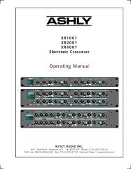
Chapter 1: Introduction to VENUE <strong>SC48</strong><br />
Welcome to the VENUE <strong>SC48</strong> live sound mixing console from <strong>Digidesign</strong>®. VENUE <strong>SC48</strong>, part of <strong>Digidesign</strong>’s modular VENUE<br />
live sound environment, is a fully self-contained console with an intuitive control surface layout, a flexible I/O scheme, powerful<br />
digital processing and integrated Pro Tools recording and playback.<br />
VENUE <strong>SC48</strong> Features<br />
Figure 1. VENUE <strong>SC48</strong> console<br />
<strong>SC48</strong> Control Features<br />
• 16 bankable input channel strips, each with a touch-sensitive<br />
fader, one multi-purpose assignable rotary encoder,<br />
solo, mute and select controls<br />
• 48 input channels with full processing, plus 8 stereo FX<br />
Returns<br />
• Built-In High-Pass Filter, Dynamics and EQ processors on<br />
each input channel strip<br />
• Level meters on each input channel strip<br />
• Channel Control section for customizable center section<br />
control of input settings, dynamics and EQ (or dyn/EQ<br />
plug-ins) settings, and Aux Sends.<br />
• 1 FlexChannel for full-time, high-resolution control of<br />
your primary input (podium, lead vocal, soloist, or other)<br />
• 8 multi-purpose Output faders strips, each with a<br />
touch-sensitive fader, one multi-purpose encoder, solo,<br />
mute and select controls<br />
• 1 Mains fader<br />
• Up to 24 31-band Graphic EQs available for Outputs<br />
• Main Busses configurable as Left–Center–Right or<br />
Left–Right+Mono<br />
<strong>SC48</strong> Audio I/O<br />
Stage I/O<br />
• 48 analog mic/line inputs with mic preamps for stage<br />
inputs. Each fully recallable input provides discrete,<br />
selectable phantom power, input gain, polarity invert,<br />
and a High-Pass filter<br />
• 16 analog output channels (expandable up to 32) to connect<br />
to mains and monitors<br />
FOH I/O<br />
• Talkback mic input, with gain and phantom power<br />
• Headphone output<br />
• Analog and digital (AES) 2-Track inputs and outputs<br />
• FWx port (FireWire 1394) providing 18 channels of fully<br />
integrated recording and playback with a compatible<br />
Pro Tools LE system<br />
Chapter 1: Introduction to VENUE <strong>SC48</strong> 3
Synchronization, Control and Utility I/O<br />
• 4 external USB 2.0 inputs for keyboard, mouse, iLok USB<br />
Smart Keys, and USB storage devices<br />
• 1 internally-mounted, secure USB 2.0 port<br />
• Video monitor port (VGA and DVI connectors) for software<br />
screen display<br />
• MIDI In and Out ports, providing 16 channels of MIDI<br />
input and 16 channels of MIDI output<br />
• Word clock I/O for digital clock synchronization<br />
• RJ-45 (100 BaseT Ethernet) port for ECx Ethernet-based<br />
remote control<br />
• 2 GPI inputs and 2 GPI outputs (DB9)<br />
• 2 three-pin XLR lamp light outputs<br />
CPU, DSP, and System Drives<br />
The VENUE <strong>SC48</strong> also houses the CPU, DSP Mix Engine, hard<br />
drive and CD-ROM drive that run the VENUE D-Show software<br />
on your system. VENUE D-Show software is installed at<br />
the factory. The CD-ROM drive lets you update or restore your<br />
VENUE system software, and install compatible plug-ins from<br />
their installer discs.<br />
Power Supply Units (PSUs)<br />
All VENUE <strong>SC48</strong> units ship with at least one universal PSU<br />
(100V to 240V nominal 50–60 Hz).<br />
System Components<br />
Included Components<br />
All VENUE <strong>SC48</strong> systems include the following:<br />
VENUE <strong>SC48</strong><br />
• VENUE <strong>SC48</strong> console<br />
• One (1) or two (2) IEC power cables, North American<br />
standard<br />
• Monitor mount (for VGA screen, screen not included)<br />
• Mouse tray (mouse/trackball not included)<br />
• Accessory tray<br />
• VENUE <strong>SC48</strong> <strong>Guide</strong><br />
• VENUE Mouse Pad<br />
• Dust cover<br />
Software CDs, iLoks<br />
• System Restore CD<br />
• ECx Ethernet Control Software Installer CD<br />
• Standalone Software Installer CD<br />
• iLok USB Smart Key (for storing plug-in authorizations)<br />
• Plug-in installer discs (if purchased) with pre-authorized<br />
iLok<br />
Additional Required Components<br />
The following components must be purchased separately:<br />
• Video Display (15-inch or greater flat-panel TFT display recommended;<br />
1024x768 minimum resolution). VGA and DVI<br />
supported.<br />
• USB keyboard and trackball/mouse (Windows compatible)<br />
Optional Components<br />
The following components are optional, and must be<br />
purchased separately:<br />
• USB flash disk (or other portable USB storage device for<br />
transfer of Show data; 512 MB or larger recommended)<br />
• Headphones with 1/4-inch jack (for FOH monitoring)<br />
• Dynamic or condenser microphone and XLR mic cable<br />
(for Talkback)<br />
• Footswitches (up to 2)<br />
• MIDI cables (for connecting external MIDI devices)<br />
• BNC cables (for connecting Word clock between the<br />
VENUE system and external digital devices)<br />
• DB9 (9-pin) cables (for connecting to GPI devices)<br />
• Two (2) Console lights<br />
4<br />
VENUE <strong>SC48</strong> <strong>Guide</strong>
VENUE <strong>SC48</strong> Expansion Options<br />
The following options can be added to VENUE <strong>SC48</strong> systems.<br />
For details on all VENUE systems and options, visit the <strong>Digidesign</strong><br />
website (www.digidesign.com).<br />
Each <strong>SC48</strong> supports a maximum of three input cards and two<br />
output cards.<br />
Water and Moisture<br />
VENUE units should be operated away from sources of direct<br />
moisture and should be kept clear of liquids that might spill<br />
into the units. If condensation is present on the unit, leave the<br />
unit to dry in ambient air for at least one hour before powering<br />
the unit on.<br />
Humidity ranges for storage and operation<br />
Inputs You can replace any of the three input cards with a new<br />
AI16 Analog Input card.<br />
Storage humidity range<br />
Operating humidity range<br />
5% to 95%, non-condensing<br />
20% to 80%, non-condensing<br />
Outputs Output can be expanded to up to 32 channels for expanded<br />
analog output, for mixed analog/digital output, or for<br />
personal monitoring.<br />
• Analog outputs can be expanded by installing an additional<br />
AO16 Analog Output card.<br />
• Analog and digital output can be added by installing an<br />
XO16 Analog/Digital Output card, providing eight<br />
digital output channels in addition to eight more analog<br />
outputs.<br />
• For personal monitor mixing, the AT16 A-Net Output<br />
card can be added to integrate VENUE <strong>SC48</strong> with<br />
Aviom® networks and Pro16 TM Series mixers.<br />
Operational Requirements<br />
Temperature and Ventilation<br />
VENUE units should be operated away from heat sources and<br />
with adequate ventilation.<br />
Hardware monitoring and automatic warnings are provided<br />
for temperature, power and other factors. For more information,<br />
see “Hardware Monitoring Window” on page 230.<br />
Storage<br />
VENUE <strong>SC48</strong> should be stored and transported at temperatures<br />
not lower than 0 degrees F (–18 degrees C) and not<br />
exceeding 140 degrees F (60 degrees C).<br />
Operation<br />
VENUE <strong>SC48</strong> should be operated at temperatures not lower<br />
than 40 degrees F (4 degrees C) and not exceeding<br />
104 degrees F (40 degrees C).<br />
Cleaning and Maintenance<br />
If you need to clean the VENUE <strong>SC48</strong> top surface, use a dry<br />
cloth. Do not apply any cleaning solutions, spray cleaners, or<br />
abrasives to the surface.<br />
Connection Requirements<br />
Power Connections<br />
Each unit requires its own power connection for primary<br />
power, and for redundant power on systems with dual PSUs.<br />
Make sure your power source is correctly rated for the number<br />
of units you are connecting. A surge-protected power source<br />
(not included) is highly recommended.<br />
VENUE <strong>SC48</strong> power supplies are capable of operating at 50 to<br />
60 Hz across a voltage range of 100 to 240 V.<br />
<strong>SC48</strong> with Redundant PSUs<br />
When using an uninterruptable power supply (UPS) it is recommended<br />
to connect one of the console power supplies to<br />
the UPS and the other directly to house power.<br />
Audio Connections<br />
All VENUE <strong>SC48</strong> analog audio inputs and outputs (except<br />
Headphones) are balanced XLR or balanced 1/4-inch connections.<br />
All VENUE <strong>SC48</strong> external digital audio inputs and outputs<br />
are AES/EBU (XLR) connections.<br />
For more information on audio connectors and specifications,<br />
see Chapter 26, “Audio Specifications.”<br />
During operation, the front and back panels of VENUE <strong>SC48</strong><br />
should be exposed to ambient air. Do not block the ventilation<br />
holes on any VENUE <strong>SC48</strong> component.<br />
Do not operate in direct sunlight or at extreme ambient temperatures.<br />
Chapter 1: Introduction to VENUE <strong>SC48</strong> 5
6 VENUE <strong>SC48</strong> <strong>Guide</strong>
Chapter 2: Configuring and Connecting <strong>SC48</strong><br />
The chapter shows how to get your <strong>SC48</strong> console up and running<br />
by doing the following:<br />
• Unpack and assemble the console<br />
• Connect the following to the VENUE <strong>SC48</strong>:<br />
• Power (AC)<br />
• Display (VGA/DVI)<br />
• USB keyboard and mouse<br />
• Audio (stage and FOH inputs and outputs)<br />
• Synchronization and control (Ethernet, MIDI, or Word<br />
clock) and lights<br />
• Power up the system<br />
• Install other optional software or updates<br />
Unpacking and Assembling the<br />
Console<br />
Unpacking the VENUE <strong>SC48</strong><br />
Always use at least two people when lifting or moving<br />
VENUE <strong>SC48</strong>.<br />
• Remove all components from the shipping packaging. Keep<br />
included items organized, making sure to keep them with<br />
their associated component after unpacking.<br />
• Place the VENUE <strong>SC48</strong> console on a table or other stable surface<br />
that leaves full access to the front and back panel connectors.<br />
• Make sure all components are free of any bags, padding or<br />
other materials.<br />
Assembling the VENUE <strong>SC48</strong><br />
VENUE <strong>SC48</strong> includes a Video Monitor Mount for your<br />
VGA/DVI monitor, a mouse tray, and an accessories tray. Follow<br />
the illustrations on the next page to attach your video<br />
monitor, mouse tray, and accessories tray to the console.<br />
Chapter 2: Configuring and Connecting <strong>SC48</strong> 7
Video Mount, Mouse Tray, and Accessories Tray<br />
Figure 2. Video Mount, Mouse Tray and Accessory Tray<br />
8<br />
VENUE <strong>SC48</strong> <strong>Guide</strong>
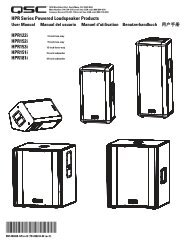
Connecting the VENUE <strong>SC48</strong><br />
The back panel provides power, audio and other connectors, as well as the master power (on/off) and reset switches.<br />
Stage Outputs<br />
Power and Reset switches<br />
Stage Inputs<br />
D<br />
E<br />
A<br />
B<br />
C<br />
Figure 3. Back panel<br />
FOH I/O<br />
Power and Display<br />
Connecting AC Power<br />
AC power connectors are located on the back panel. One (or<br />
two) male, 3-pin North American standard IEC power sockets<br />
with cable retaining clips are provided (one on standard <strong>SC48</strong><br />
units, and two on units ordered with a second redundant<br />
power supply).<br />
Connecting USB Keyboard and Mouse<br />
There are three USB 2.0/Type A ports on the front of the <strong>SC48</strong><br />
to connect a USB keyboard, trackball/mouse, or key disks.<br />
<strong>SC48</strong> front<br />
Front panel USB ports for keyboard and mouse<br />
Power<br />
Power connectors on the back panel (two-PSU model shown)<br />
To connect power to <strong>SC48</strong>:<br />
• Connect the included IEC power cable(s) between the<br />
Power connector(s) on <strong>SC48</strong> and your power source.<br />
To connect a USB keyboard and trackball/mouse:<br />
• Connect them to the USB ports on the front of <strong>SC48</strong>.<br />
Two more USB ports are also provided, one on the back panel<br />
and one concealed within the console itself. For more information,<br />
see “Secure USB Port” on page 12.<br />
Connecting a VGA or DVI Display<br />
One VGA connector and one DVI connector are provided to<br />
connect a VGA/DVI-compatible video display (not included).<br />
VGA connector<br />
DVI connector<br />
monitor<br />
VGA and DVI display connectors on the back panel<br />
To connect a computer display:<br />
• Plug a VGA or DVI display cable into either the VGA or DVI<br />
connector. (These two ports mirror each other; they are not<br />
discrete video outputs.)<br />
Chapter 2: Configuring and Connecting <strong>SC48</strong> 9
Connecting Audio<br />
<strong>SC48</strong> provides 48 analog mic/line inputs and up to 32 analog line outputs for stage audio, and a variety of analog and digital audio<br />
inputs and outputs for FOH/mix position audio. You can use an analog multicore snake cable (not included) to carry multiple<br />
stage inputs and outputs to and from the console, or you can connect mics, instruments and other sources directly to <strong>SC48</strong> analog<br />
mic/line inputs, and connect <strong>SC48</strong> outputs directly to the inputs on your house/mains, monitors, or other destinations.<br />
Stage Inputs 1–48<br />
(Analog Mic/Line XLR Inputs)<br />
The Stage Input section provides 48 channels of analog mic/line inputs (XLR), to connect stage input sources. Use a standard<br />
analog snake, or connect sources directly to Stage inputs 1–48.<br />
analog multicore (snake)<br />
A<br />
1–16<br />
B<br />
17–32<br />
Stage<br />
Inputs<br />
C<br />
32–48<br />
Figure 4. <strong>SC48</strong> I/O slots A–C for stage inputs 1–48<br />
Stage Outputs 1–16<br />
(Analog Line XLR Outputs)<br />
The Stage Output section provides up to 32 channels of stage output (XLR), to connect to house/mains, monitors, additional<br />
zones, or feeds to other devices.<br />
to<br />
house/<br />
mains,<br />
monitors<br />
zones<br />
Stage<br />
Outputs<br />
D<br />
1–16<br />
E<br />
17–32<br />
Figure 5. <strong>SC48</strong> I/O slots D and E for stage Outputs 1–32<br />
On standard systems with a single AO16 card in slot D, hardware outputs are numbered 1–16. Adding an AO16 or XO16 output<br />
expansion card will add outputs to slot E, and those hardware outputs will be numbered 17–32.<br />
10<br />
VENUE <strong>SC48</strong> <strong>Guide</strong>
FOH Inputs and Outputs<br />
The FOH I/O section provides connectors and controls for Talkback, 2-Track, Pro Tools and other sources and destinations used<br />
at the mix position, as explained in the following sections.<br />
1394<br />
FWx<br />
for ProTools LE<br />
GPI MIDI<br />
2-Tr<br />
AES<br />
Footswitch Word Clock<br />
2-Tr<br />
Analog<br />
Gain 15V<br />
Input<br />
Talkback<br />
Figure 6. FOH connectors and controls<br />
Talkback<br />
The Talkback Mic connector and controls allow connection of<br />
a microphone for communicating to stage or through the<br />
Mains. The Talkback Mic input is a female XLR connector. The<br />
Talkback input has adjustable gain and switchable +15V<br />
phantom power.<br />
1394 (FWx)<br />
This Firewire port is for integrated Pro Tools recording and<br />
playback with VENUE FWx. FWx provides 18 channels of I/O<br />
directly to a compatible Pro Tools LE system.<br />
For more information, see Chapter 30, “FWx.”<br />
To connect a mic for Talkback:<br />
• Plug a dynamic or condenser talkback microphone into the<br />
back panel Talkback connector.<br />
Do not connect an intercom system directly to the Talkback<br />
input, as some intercom systems use a signalling voltage<br />
which can damage the <strong>SC48</strong> input card.<br />
To adjust Talkback Gain:<br />
• Turn the back panel Gain knob (or adjust the on-screen<br />
Talkback level control in the Options > Misc page).<br />
To enable or disable phantom power on the Talkback input:<br />
• Slide the +15V switch to the right “on” position<br />
2-Track Digital Inputs and Outputs<br />
These 2-Track digital connections are used for input and output<br />
of digital audio material. The stereo AES/EBU connectors<br />
support 24-bit, 48 kHz digital signals. Input signals with other<br />
sample rates are sample-rate converted to 48 kHz.<br />
2-Track Analog Inputs and Outputs<br />
These 2-Track analog connections are used for input and output<br />
of analog audio material. These are balanced 1/4-inch TRS<br />
connectors.<br />
Connecting Synchronization, Control,<br />
and Lights<br />
<strong>SC48</strong> provides the following connectors for synchronization,<br />
control, and illumination.<br />
Word Clock<br />
To sync an external digital device to <strong>SC48</strong> Word Clock Out:<br />
Connect the Word Clock Out on the <strong>SC48</strong> back panel to the<br />
corresponding digital device. Set the external device to slave<br />
to the incoming word clock signal.<br />
External digital device<br />
MIDI<br />
Set device to slave to<br />
incoming Word Clock<br />
BNC<br />
<strong>SC48</strong> (back)<br />
Word Clock Out<br />
Using word clock from <strong>SC48</strong> to clock an external device<br />
These MIDI In and Out Ports provide 16 channels of MIDI input<br />
and 16 channels of MIDI output to the system. The<br />
MIDI I/O ports are used in sending and receiving Snapshot<br />
MIDI messages, and in receiving MIDI Time Code from<br />
external devices.<br />
To make MIDI connections to <strong>SC48</strong>:<br />
• Connect a compatible MIDI device to the MIDI In and MIDI<br />
Out ports.<br />
Chapter 2: Configuring and Connecting <strong>SC48</strong> 11
Footswitch 1 and 2<br />
Two female 1/4-inch TS footswitch jacks are provided for<br />
switch input. Footswitches can be normally open or normally<br />
closed, latching or momentary. Functions are assigned to<br />
these jacks using the on-screen Options > Events page.<br />
GPI Port<br />
A 9-pin, female DB9 connector provides a 2-in/2-out GPI General<br />
Purpose Interface (GPI).<br />
For specifications, wiring diagrams and pinouts, see<br />
Chapter 29, “Console Reference.”<br />
GPI Applications<br />
GPI inputs are connected to the outputs of a variety of switching<br />
devices such as footswitches, momentary or latching<br />
push-button switches, or logic outputs of a larger show control<br />
system. Example applications of GPI inputs include remote<br />
toggling of a console function such as Talkback, muting<br />
a channel, or recalling a specific snapshot.<br />
GPI outputs connect to compatible inputs found on a variety<br />
of external devices such as LEDs, small relays, power sequencers,<br />
and logic inputs on show control systems.<br />
Example applications of GPI outputs include the following:<br />
• Triggering a sound effects playback machine when a specific<br />
snapshot is recalled.<br />
• Lighting a tally light whenever a fader is raised above a minimum<br />
threshold.<br />
• Flashing or lighting a custom beacon or LED as a reminder<br />
of vital console mode, such as Solo in Place.<br />
• Initiating power up of amplifiers and other down-stream<br />
systems when VENUE system is started up or shut down.<br />
Console Lights<br />
Two XLR3-F jacks on the top of the unit let you connect console<br />
lights (not included).<br />
To use the console lights:<br />
• Plug the console lights into the two Console Light XLR jacks<br />
on the upper part of the back panel.<br />
You can adjust the brightness of the console lights, and separately<br />
for the LED and displays, from the Options > Interaction<br />
page (see “Lights” on page 59).<br />
Secure USB Port<br />
One USB 2.0 port is located within the console itself to connect<br />
and securely protect an iLok Smart Key. Use this port to<br />
keep one “master” iLok and its plug-in assets with the console<br />
at all times, safe from damage or loss. See Figure 2 on page 8<br />
for an illustration that shows the location of the internal USB<br />
port.<br />
To access the internal USB port:<br />
1 Remove the two screws holding the tray in place and slide<br />
the tray out.<br />
2 Insert (or remove) your iLok.<br />
3 To reassemble, make sure the iLok is firmly seated in the tray<br />
before sliding it back into the unit. Replace the two screws to<br />
secure the tray.<br />
GPI functions are managed using the Events List in the<br />
Options > Events window. For more information, see<br />
Chapter 22, “Events.”<br />
To connect GPI devices to VENUE <strong>SC48</strong>:<br />
1 Connect one end of a DB9 cable (not included) to the GPI<br />
port on the back panel of VENUE <strong>SC48</strong>.<br />
2 Connect the other end to the appropriate GPI port on the<br />
external device.<br />
ECx<br />
One RJ-45 connector is provided for remote Ethernet control<br />
of VENUE from a client computer (Mac or Windows laptop,<br />
tablet, or similar).<br />
For more information on ECx, see Chapter 31, “ECx.”<br />
12<br />
VENUE <strong>SC48</strong> <strong>Guide</strong>
Powering Up the System<br />
Faders move when power is turned on. Before powering up<br />
the system, make sure all fader paths are clear.<br />
Power up the system in the following sequence:<br />
1 Press the Power switch on the back panel of VENUE <strong>SC48</strong><br />
(located on the back panel, center top).<br />
2 Turn on any connected computers for recording/playback.<br />
3 Turn on the audio monitoring system.<br />
Power switch<br />
Power<br />
Powering Down the System<br />
Power down the system in the following sequence:<br />
1 Turn off the audio monitoring system.<br />
2 Turn off any connected computers for recording/playback.<br />
3 Power down VENUE <strong>SC48</strong>.<br />
It is not possible to accidentally power off the console by<br />
pressing the Power switch momentarily.<br />
Setting the System Clock<br />
When you first work with a VENUE system, make sure the system<br />
clock time, date and time zone are set appropriately. The<br />
system clock setting can affect data synchronization with portable<br />
storage devices. See “Synchronizing Settings, Shows and<br />
Presets” on page 165.<br />
The system clock time can be shown in the Status bar for constant<br />
time-of-day display. For more information, see “System<br />
Clock” on page 57.<br />
Changing the system clock while using a timed iLok license<br />
(for a plug-in with a demo period, or for a plug-in rental)<br />
may expire the plug-in authorization.<br />
After setting the system clock, do either of the following:<br />
• To get started learning the console and configuring it, see<br />
Chapter 3, “VENUE <strong>SC48</strong> Control Overview.”<br />
– or –<br />
• If you want to install any other optional software first<br />
(such as ECx, or included plug-ins) see the next section<br />
(“Installing Other Optional Software” on page 13).<br />
Installing Other Optional Software<br />
ECx, Plug-ins, and Other<br />
After having unpacked, assembled, connected, and powered<br />
up your <strong>SC48</strong> system, you can go ahead and add any additional<br />
software and plug-ins as explained in the following sections.<br />
VENUE <strong>SC48</strong> is loaded at the factory with the most recent version<br />
of its operating software (VENUE D-Show software), as<br />
well as the core set of VENUE plug-ins. You must manually install<br />
software for the following:<br />
ECx Ethernet Control If you want to take advantage of the<br />
built-in Ethernet remote control option, install the ECx software<br />
from its included installer disc. For instructions, see<br />
Chapter 31, “ECx.”<br />
Plug-ins All plug-ins (except the included plug-ins) must be installed<br />
manually from their installer discs, or from copies of<br />
the installers transferred to your USB key disk or other storage<br />
device. For more information, see Chapter 19, “Plug-Ins.”<br />
About Digital Input and Sample Rate<br />
Conversion<br />
VENUE systems operate at a native sample rate of 48 kHz. The<br />
2-Track AES inputs on the <strong>SC48</strong> provide sample rate conversion<br />
on input, letting you connect a wide variety of digital<br />
sources without having to be concerned with synchronization<br />
and clock connections.<br />
Sample rate conversion does, however, induce processing delay<br />
to the incoming digital signal.<br />
Sample Rate Conversion Latency<br />
The following table illustrates the sample rate conversion processing<br />
delay at various sample rates.<br />
Minimum Additional Latency due to Sample Rate Conversion<br />
External Sample Rate<br />
32 kHz 1.50 ms<br />
44.1 kHz 1.09 ms<br />
48 kHz 1.00 ms<br />
SRC Process Delay<br />
88.2 kHz 0.848 ms<br />
96 kHz 0.833 ms<br />
Chapter 2: Configuring and Connecting <strong>SC48</strong> 13
14 VENUE <strong>SC48</strong> <strong>Guide</strong>
Part II: System Description
Chapter 3: VENUE <strong>SC48</strong> Control Overview<br />
VENUE <strong>SC48</strong> Top Panel<br />
The following figure identifies the main sections of the VENUE <strong>SC48</strong> control surface:<br />
Snapshots<br />
Console Mode<br />
Mute Groups/<br />
Function<br />
Bus Outputs<br />
Meters<br />
Monitoring<br />
View<br />
Mains Mode<br />
D<br />
A<br />
C<br />
B<br />
Global A Input Channel Strips 1–16<br />
Modifiers<br />
B Output Masters Section<br />
C Flex Channel<br />
D ACS (Assignable Channel Section): Selected Channel, Bus Assign and Channel Control<br />
E Masters and Global Controls (Snapshots, Mute Groups, Monitoring, Console and View Modes)<br />
Figure 7. Main control sections on VENUE <strong>SC48</strong><br />
VENUE <strong>SC48</strong> provides 16 bankable input channel strips in the Input Channel section, eight bankable output channel strips plus<br />
a Mains fader in the Output Masters section, the Flex Channel strip, and the ACS (or Selected Channel sections) including Input, Bus<br />
Assigns and Channel Control. Surrounding these sections are the masters and global modifiers sections (Console Mode, snapshots,<br />
metering, monitoring, and View Mode).<br />
Chapter 3: VENUE <strong>SC48</strong> Control Overview 17
Input Channels and Faders<br />
The Input section provides 16 faders and other controls for Input Channels and FX Returns. Additional channels are banked to<br />
the 16 faders using the Bank A, B, C and D switches. All 16 input channels bank together.<br />
Input faders can also be assigned to control FX Returns 1–8, or the output EQ (graphic EQ).<br />
Each input channel strip includes a channel fader, channel Select, Mute and Solo switches, a rotary encoder, LCD display area and<br />
meters for channel level and dynamics gain reduction. The encoders and associated assignment switches access Gain, Pan, HPF<br />
and Aux Sends. Each bank of eight input channels provides a two-row LCD display that shows channel name, parameter names,<br />
values and other data as appropriate for the current action. Additional input parameters are controlled by selecting one or more<br />
channels to make them the target of the Selected Channel sections.<br />
Clip and Safe LEDs<br />
Bus Assign LEDs<br />
Meters<br />
Encoder Switches<br />
Encoders and LEDs<br />
LCD Display<br />
Select<br />
Solo<br />
Mute<br />
FX Returns<br />
Banks A/B/C/D<br />
Figure 8. Input controls (Input Channels 1–8 shown)<br />
Faders 1–8<br />
GEQ<br />
Clip and Safe LEDs<br />
Safe LED<br />
At the top of each input strip are the Hidden Bank Clip and<br />
Safe LEDs.<br />
Hidden Bank Clip LED<br />
The Hidden Bank Clip LED lights to indicate a meter clip on<br />
an Input Channel or FX Return at the corresponding position<br />
in an alternate bank of channels. It gives you an indication of<br />
extreme signal level in a currently hidden (“off-bank”) layer.<br />
This indicator obeys the same clipping threshold display rules<br />
as the Input Channel meters (as set in the Options > Interaction<br />
page).<br />
The Safe LED indicates either an input strip’s Automation,<br />
Solo, or Bank safe status, depending on the current Input Safe<br />
Switch setting. See “Input Safe Switches” on page 58.<br />
Auto Safe Mode If the Safe LED is lit, the channel will not respond<br />
to Snapshot-driven changes. If the LED is off, that<br />
channel will respond to any applicable changes driven by<br />
Snapshots (subject to the current Recall Safe settings, if any).<br />
Solo Safe Mode If the Safe LED is flashing slowly, the channel<br />
will not respond to solo commands (it will not be muted if another<br />
channel’s solo button is pressed). If the LED is off, that<br />
channel will be silenced when soloing another channel.<br />
18<br />
VENUE <strong>SC48</strong> <strong>Guide</strong>
Bank Safe Mode If the Safe LED is flashing rapidly, the channel<br />
remains in place on the top fader layer when a different<br />
Bank (A–D) is selected (it will be unlinked from console banking).<br />
If the LED is off, the channel follows banking.<br />
Stereo LED<br />
A single yellow LED indicates a stereo input channel. The stereo<br />
channel LED flashes if a 10 dB or greater offset is detected<br />
between left and right inputs.<br />
Bus Assigns LEDs<br />
These red LEDs indicate Mains bus (LR or C/M) assignment.<br />
Color<br />
(none)<br />
Channel Status<br />
Mono<br />
If the LR LED is lit, the input channel feeds the Left and<br />
Right Main busses in either L–R or L–C–R panning mode (regardless<br />
of the Stereo Pan LED status).<br />
If the C/M LED is lit, the input channel feeds the C (center)<br />
bus from the pan in L–C–R mode, or the M (mono) bus before<br />
the pan. Stereo channels are summed to the mono bus.<br />
Meters<br />
LR<br />
Bus Assign indicator LEDs on an Input Channel<br />
C/M<br />
Each Input Channel provides a Comp/Lim gain reduction meter<br />
and an input level meter, plus LEDs for EQ, Stereo and Gate<br />
status.<br />
Yellow<br />
Stereo<br />
Gate Status LED<br />
A single bi-color LED shows the current Expander or Gate<br />
status.<br />
Input Encoders and Assignment Controls<br />
Each input channel features one assignable input encoder that<br />
can be assigned to control input gain, HPF corner frequency,<br />
pan/balance/width, and sends (Auxes).<br />
The Encoder Assignment switches, located to the left of the<br />
row of encoders, determine the function of the encoders on<br />
Input Channels. The LCD displays the current function (see<br />
“Input Channel LCD Displays” on page 20).<br />
Comp/Lim<br />
Gain Reduction<br />
Input Level<br />
EQ In/Out<br />
Stereo<br />
Input channel meters and LEDs<br />
Comp Gain Reduction Meter<br />
Gate<br />
Encoders<br />
LCD<br />
A 3-segment meter displays gain reduction for the channel<br />
compressor/limiter.<br />
Input Level Meter<br />
A 6-segment meter displays input level and indicates clipping.<br />
The top-most LED is bi-color and lights red to indicate clipping<br />
at any point in the channel.<br />
For meter scales, see “Channel Meters” on page 107.<br />
EQ Status LED<br />
A single red LED indicates EQ In/Out status as shown in the<br />
following table.<br />
Color<br />
(none)<br />
Red<br />
EQ Status<br />
Not in circuit<br />
In circuit<br />
Encoder Assignment Switches<br />
Input encoders, assignment switches, and LCD (inputs 1–8)<br />
Rotary and Switch Functionality<br />
VENUE rotary encoders are dual-function controls that provide<br />
rotary and switch functions. In addition to adjusting parameters<br />
by turning the encoder, you can toggle parameters<br />
(such as taking the HPF in or out of circuit) by pressing the encoder<br />
knob.<br />
Encoder LEDs<br />
Two types of LEDs surround each encoder:<br />
The LED ring around the encoder displays the relative position<br />
of its currently assigned parameter.<br />
Below each encoder is an indicator LED, which indicates parameter<br />
status (in/out), default setting, or other conditions related<br />
to the current encoder function.<br />
Chapter 3: VENUE <strong>SC48</strong> Control Overview 19
Switches in the Encoder section assign each of the following<br />
parameters to the Input encoders:<br />
Gain<br />
Gain assigns the encoders to control input gain according to<br />
the range available for this input (head amp gain for analog<br />
inputs, digital gain for digital or line inputs). Pressing and<br />
holding the encoder initiates Gain Guess, in which a nominal<br />
input gain level is automatically set based on the incoming<br />
signal.<br />
Pan<br />
Pan assigns the encoders to control channel Pan if the channel<br />
is mono, or stereo channel balance if the channel is stereo.<br />
The indicator LED lights when the pan is at center.<br />
HPF<br />
Display<br />
Source Switch<br />
The Source switch in the Display section changes the Channel<br />
Name display to show the source input that is feeding each<br />
channel.<br />
Input Channel LCD Displays<br />
There are two Input Channel LCD displays, one each for<br />
Inputs 1–8 and 9–16.<br />
Each LCD provides two rows of data with six characters per<br />
row, per input channel. The upper and lower rows let you see<br />
more than one type of channel data simultaneously, such as<br />
channel name in the lower row and Aux Send levels in the upper<br />
row. Data display depends on the current encoder assignment.<br />
Input Encoder Assignments and Values<br />
HPF (High Pass Filter)<br />
HPF assigns the encoders to control the HPF corner frequency.<br />
Pressing the encoder toggles the built-in HPF in and out of circuit.<br />
If the LED is lit, the filter is in circuit.<br />
Send 1–2 to Send 15–16<br />
These switches let you select one of two Aux sends in<br />
odd/even pairs (Send 1–2 through Send 15–16).<br />
With mono sends, the first press of the switch selects the<br />
odd numbered send (1, 3, 5, or 7) and the second press selects<br />
the even numbered send (2, 4, 6, or 8). The switch lights green<br />
for the odd-numbered selection, or yellow for the even-numbered<br />
selection.<br />
With stereo-linked sends, the first press of the switch controls<br />
level for the bus pair, and the second press controls pan<br />
for the bus pair. The switch lights green for level control, or<br />
yellow for pan control.<br />
Pressing an encoder toggles the send on or off. When the send<br />
level is shown on the LED ring and the send is off, a single LED<br />
lights. When the send is on, all LEDs light in a clockwise sequence<br />
from the lower left to the send level.<br />
Flip to Faders<br />
When enabled, the current encoder parameter is mapped to<br />
the faders. It can still be controlled from the encoder row, so<br />
the channel fader mirrors the setting.<br />
Using Flip to Faders, it is possible to control send level from<br />
the faders, and pan on the encoders. For information, see<br />
Chapter 11, “Aux Sends.”<br />
The current encoder assignment, parameter or value is displayed<br />
in the top row of the input displays. There are two<br />
states the top row can be in: Parameter Value mode and Parameter<br />
Name mode.<br />
When necessary, the display abbreviates functions as shown<br />
in the following table.<br />
Table 4. Encoder Assignment Displays<br />
Switch<br />
Gain<br />
Pan<br />
Send (n)<br />
Flip to Faders<br />
Select Switch<br />
Display<br />
Input Gain<br />
Input Pan<br />
HPF Frequency<br />
Aux (n) Level<br />
Aux (n) Pan (stereo-linked sends only)<br />
Variable Group (n) Level<br />
Variable Group (n) Pan (stereo-linked sends only<br />
Aux (n) Level and Pan (stereo-linked sends<br />
only)<br />
The Select switch on each channel is used to target the channel<br />
in the Selected Channel and/or Flex Channel sections, and<br />
to include the channel in Multi-Select and Multi-Assign functions.<br />
A lit Select switch indicates the channel is selected. The<br />
name of the currently selected channel is displayed in the<br />
Channel Name display and in the Selected Channel display.<br />
When multiple channels are selected, the Channel Name display<br />
indicates which channel is the ACS target.<br />
20<br />
VENUE <strong>SC48</strong> <strong>Guide</strong>
Solo Switch<br />
The Solo switch toggles the solo state of that channel. When<br />
enabled, the Solo switch LED is lit. When the channel is in<br />
Solo Safe mode, the Solo switch LED flashes. Channel Solo<br />
latches on a momentary press, and automatically releases if<br />
held for 2 seconds or more and released.<br />
Mute Switch<br />
The Mute switch mutes the channel at the (pre-fader) mute<br />
point.<br />
Input Faders and Banking<br />
Each channel features a 100mm motorized, touch-sensitive<br />
fader. The Options > Interaction screen lets you enable<br />
touch-sensitive channel selection. When enabled, touching a<br />
channel fader automatically selects that channel and makes it<br />
the Selected Channel.<br />
Bank A–D<br />
Faders<br />
(1–8)<br />
FX Returns<br />
1–8<br />
Fader Banking Controls<br />
Bank A–D Banks the Input strips. Up to four banks (A through<br />
D) can be used to access up to 48 inputs from the 16 Input<br />
fader strips. Bank A is channels 1–16, Bank B is channels<br />
17–32, and so on.<br />
FX Returns Banks FX Return channels 1–8 to Input fader strips<br />
1–8.<br />
Important input channels can be put in Bank Safe mode, to<br />
keep them at the top layer of faders at all times (ignore input<br />
banking). For more information, see “Bank Safe Mode<br />
for Input Safe Switches” on page 34.<br />
GEQ (Graphic EQ) Banks bands of graphic EQ to the faders.<br />
Graphic EQs can be used on outputs only. For more information,<br />
see Chapter 18, “EQ.”<br />
Global Modifier Switches<br />
To the left of the Bank A–D switches are the global modifier<br />
switches.<br />
Global<br />
Modifiers<br />
Input fader banking and assignment switches<br />
GEQ<br />
20–630 Hz<br />
800–20kHz<br />
The faders can be moved even when they do not sense a<br />
touch. This allows use of the faders while wearing gloves,<br />
and also lets you “throw” a fader and have it stay where it<br />
lands (not snap back to where it was last touched).<br />
Global<br />
Modifiers<br />
Global modifiers<br />
Multi-Select (Shift) Lets you select multiple channels, and lets<br />
you select multiple items in lists.<br />
Default (Alt) Lets you reset a parameter, section, or channel to<br />
default values. This switch also enables certain modes such as<br />
Show VCA Members mode.<br />
Fine (Ctrl) Lets you adjust rotary encoders with greater resolution<br />
for finer control, or to select non-adjacent items in lists.<br />
User This switch is reserved for future use.<br />
For examples of these switches in use, see “Global Modifier<br />
Switches” on page 29.<br />
Chapter 3: VENUE <strong>SC48</strong> Control Overview 21
Selected Channel Sections (ACS)<br />
The Selected Chan (selected channel, or Assignable Channel<br />
Sections) include the Inputs, Bus Assigns, and Channel Control<br />
sections, along with stereo channel meters, an LCD display,<br />
and dynamics meters.<br />
The Stereo LED lights solid when a stereo input or output is<br />
targeted. The Solo LED flashes any time a channel is in PFL,<br />
AFL or Solo in Place mode.<br />
Dynamics<br />
Gain Reduction Meters<br />
Inputs<br />
Channel Control<br />
The meters in the Dynamics section provide dedicated metering<br />
for built-in and plug-in dynamics processors.<br />
Bus Assigns<br />
Bus Assigns<br />
Dynamics<br />
Gain Reduction<br />
Meters<br />
Selected Channel control and display sections<br />
The Bus Assigns switches are the primary routing controls for<br />
the currently selected channel, letting you bus it directly to<br />
the Mains (L–R) bus or to any other mono or stereo group.<br />
L–R<br />
Group 1–8<br />
In addition, the Flex Channel provides a dedicated fader,<br />
channel encoder, Select, Solo and Mute switches for the currently<br />
selected channel, with the ability to be unlinked from<br />
input channel banking and selection (“latch” your most important<br />
input to the Flex Channel). For more information,<br />
see “Flex Channel” on page 23.<br />
C/Mono<br />
Bus assign switches<br />
Stereo Pan<br />
Input<br />
This section provides switches for channel phantom power,<br />
input pad, polarity (phase), and Safe status.<br />
+48V 20 dB Pad<br />
Channel Control<br />
Gain, EQ, Dynamics, Plug-ins, Auxes<br />
Channel Control is the “center section” panel for consistent<br />
display and control of EQ, dynamics, and plug-in processing<br />
and Auxes.<br />
Input Polarity<br />
Safe<br />
Meters<br />
Encoders<br />
Stereo<br />
Solo<br />
LCD Display<br />
Selected Channel Input controls, meters and displays<br />
LCD<br />
Meters<br />
Below the Inputs switches are two 10-segment Selected Channel<br />
meters, LEDS for Stereo and Solo state and a 6-character<br />
LCD display.<br />
The dual, 10-segment, bi-color LED meters indicate input level<br />
and clip status for the currently targeted or Soloed channel.<br />
User Input Plug-In EQ Comp/ Exp/ Aux Sends<br />
Lim Gate 1-8 9-16<br />
Channel Control encoders, LCD and mode switches<br />
For optimal mixing flexibility, you can assign up to 8 parameters<br />
as a custom User layout.<br />
For Selected Channel metering scale, see “Selected Channel<br />
Level Meters” on page 108.<br />
The 6-character Selected Channel display shows the name of<br />
the currently selected channel. The Selected Channel display<br />
temporarily reverts to a parameter display mode any time an<br />
encoder is adjusted on the selected channel.<br />
22<br />
VENUE <strong>SC48</strong> <strong>Guide</strong>
Flex Channel<br />
The Flex Channel is a special fader strip that provides a dedicated<br />
fader, encoder, and LCD display along with channel Select,<br />
Solo and Mute switches for the currently selected channel.<br />
The Flex Channel can also be latched to any channel for<br />
uninterrupted control of any vital channel.<br />
Flex Channel<br />
Encoder<br />
Select/Latch<br />
Solo<br />
Mute<br />
Fader<br />
In its default Selected Channel mode the Flex Channel mirrors<br />
the currently selected channel. The Flex Channel encoder follows<br />
the current Encoder Assignment mode (gain, pan, HPF,<br />
or a send). The Flex Channel LCD shows the current channel<br />
name.<br />
To latch a channel to the Flex Channel from the console:<br />
1 Select the input or output channel you want assigned to the<br />
Flex Channel.<br />
2 Press the Select/Latch switch on the Flex Channel. A dialog<br />
appears on-screen asking you to confirm the assignment.<br />
Double-press the Select/Latch switch to latch that channel<br />
and clear the confirmation dialog in one action.<br />
3 Press the Flex Channel Select/Latch switch again (or click<br />
Latch on-screen) to confirm the assignment. Click Cancel to<br />
cancel the assignment.<br />
To latch the Flex Channel on-screen:<br />
• Right-click on the desired channel in the lower fader display<br />
and choose Latch .<br />
To return to Selected Channel mode, do one of the following:<br />
• Double-press the Flex Channel Select/Latch switch. The<br />
(former) channel assigned to the Flex Channel becomes the<br />
selected channel in the ACS, and the Flex Channel reverts to<br />
Selected Channel mode.<br />
– or –<br />
Right-click the currently latched channel on-screen in the<br />
lower fader display and choose Unlatch .<br />
In the optional Flex Channel mode, the Flex Channel is<br />
latched to the currently selected channel. Selecting a different<br />
channel or changing fader banks will not change the assignment<br />
of the Flex Channel, letting you keep constant control<br />
over your most important signal. The Flex Channel LCD is red<br />
when latched and green when not latched.<br />
Chapter 3: VENUE <strong>SC48</strong> Control Overview 23
Output Masters<br />
The Output Masters section includes eight bankable output channel strips, each with a fader, encoder and channel switches. The<br />
Mains fader provides master level control over the Mains (house) output.<br />
Output Encoders<br />
LCD Display<br />
Select<br />
AFL<br />
Mute<br />
Prev and Next Page<br />
Pan<br />
Insert Mode<br />
Next Plug-in<br />
Multi-Assign/Show VCA Members<br />
Select Mains<br />
Mute Mains<br />
Mains fader<br />
Output Faders<br />
Output bank switches<br />
Figure 9. Input controls (Input Channels 1–8 shown)<br />
Mains<br />
Mains Fader<br />
The Mains fader provides a single level control for the current<br />
Mains output.<br />
Mains Select and Mute<br />
Above the Mains fader are Select and Mute switches for selecting<br />
and muting the current mains output, respectively.<br />
Output Faders<br />
The eight Output Faders control level for Aux 1–8, Aux 9–16,<br />
Matrix busses, Group busses, and VCAs.<br />
Output Fader Bank Switches<br />
The Output faders and encoders are banked to the desired bus<br />
using the Output Faders switches.<br />
Aux 1–8 Assigns the Output Faders to Aux 1–8 levels.<br />
Aux 9–16 Assigns the Output Faders to Aux 9–16 levels.<br />
VCAs Assigns the Output Faders to control VCAs.<br />
Output Mute, AFL and Select Switches<br />
Above the faders are the Mute, AFL and Select switches.<br />
Output Encoders and Display<br />
The eight Output Encoders adjust Group bus pan to Mains,<br />
Matrix input levels and pan, or plug-in parameters (when in<br />
Inserts mode).<br />
The Output Masters LCD display is a two-row display that<br />
shows 6 characters in each row, per output bus. The display<br />
shows the name, parameter or value currently being controlled<br />
in the Output Masters section.<br />
The Prev Page and Next Page switches light to indicate additional<br />
functions depending on the selected output or plug-in.<br />
When lit, pressing either switch scrolls the Output Encoders.<br />
The Inserts Mode switch puts the encoders in Inserts mode, in<br />
which the Output encoders select and adjust plug-ins. The<br />
Next Plug-in switch advances you to the next plug-in inserted<br />
on the current channel.<br />
Matrixes Assigns the Output Faders to control Matrix mixer<br />
output levels.<br />
Groups Assigns the Output Faders to control Group levels.<br />
24<br />
VENUE <strong>SC48</strong> <strong>Guide</strong>
Master and Global Controls<br />
Global and master controls are located in sections with a dark<br />
background, and include the Console Mode, Snapshots, Mute<br />
Groups/Function, Monitoring and View Mode sections.<br />
Console Mode<br />
The Config Mode switch toggles the system between Config<br />
and Show modes. See “Config Mode and Show Mode” on<br />
page 28.<br />
Mute Groups<br />
Mute Groups let you quickly mute multiple channels at the<br />
same time. You can create and recall up to eight Mute Groups<br />
by assigning one or more channels to each Mute Group.<br />
See Chapter 16, “Muting and Mute Groups.”<br />
Function Switches<br />
In Function mode, this section provides eight Main Function<br />
switches. The default assignments for the first four Function<br />
switches include Preview mode on/off (F1), Copy (F3) and<br />
Paste (F4).<br />
Function switches can be assigned to perform any number<br />
of actions using the Events List. For more information, see<br />
Chapter 22, “Events.”<br />
Console Mode<br />
Snapshots<br />
The Snapshots section provides Store, Recall, Previous, Next,<br />
and Preview mode switches, along with a Select encoder and a<br />
6-character Snapshot LCD display.<br />
Store<br />
Recall<br />
Select<br />
Cancel<br />
This switch cancels the current operation, such as Multi-Select<br />
or Multi-Assign modes.<br />
View Modes<br />
The View Mode switches (Options, Inputs, Outputs, Filing,<br />
Snapshots, Patchbay, Plug-ins) display the corresponding<br />
pages on-screen. Pressing a View Mode switch repeatedly cycles<br />
through the individual tabs of that page. For example,<br />
pressing the Patchbay switch once displays the Patchbay page.<br />
Pressing Patchbay again cycles through various tabs within<br />
the Patchbay page.<br />
Previous<br />
Snapshots<br />
For more information, see Chapter 21, “Snapshots.”<br />
Mute Groups/Function<br />
Next<br />
Provides Mute Group assignment and selection in default<br />
Mute Groups mode, or can be switched to provide eight Function<br />
switches (F keys) in Function mode. The global Cancel<br />
switch is also located in this section.<br />
Options<br />
Inputs<br />
Filing<br />
Patchbay<br />
Snapshots<br />
Outputs<br />
Snapshots<br />
Plug-ins<br />
Mute Groups/Function<br />
Chapter 3: VENUE <strong>SC48</strong> Control Overview 25
Monitoring<br />
The Monitoring section provides a level encoder for the Headphone<br />
output (Monitor bus outputs).<br />
Headphones<br />
Solo Clear<br />
Mix to Monitors<br />
Monitoring<br />
Monitor bus delay can be set on-screen in the Options > Busses<br />
page.<br />
Meters<br />
The Meter section includes the following:<br />
Meters<br />
Bus Output Meters<br />
Metering<br />
Main<br />
Bus Output Meters 1–8<br />
Eight Bus Output meters provide selectable metering of Output<br />
busses.<br />
L CM R<br />
The Mains meters provide constant level indication of the<br />
house (Mains) output.<br />
For more information, see Chapter 14, “Metering.”<br />
26<br />
VENUE <strong>SC48</strong> <strong>Guide</strong>
Chapter 4: Basic Commands and Modes<br />
Control Overview<br />
Most VENUE features and controls that are used during a performance<br />
are available from both the console and on-screen.<br />
Changes made on one are immediately reflected in the other,<br />
letting you use almost any combination of console and screen<br />
controls to mix.<br />
The software screen is not required in order to mix a performance,<br />
as all essential mixing controls are provided on the<br />
console. However, the screen is essential when setting up and<br />
configuring the system before a performance.<br />
Software-Only Controls and Displays<br />
Many configuration settings and options are only available<br />
on-screen, including hardware configuration settings, busses,<br />
plug-in installation, and system diagnostics. For more information,<br />
see “System” on page 51.<br />
Tool Tips<br />
With the mouse or trackball, place the cursor over a screen<br />
item to see a brief explanation in the banner display.<br />
Tool Tip<br />
Cursor<br />
Status bar showing Tool Tip<br />
Status Messages<br />
The banner display alerts you to certain operating conditions<br />
such as Multi-Select and Multi-Assign modes.<br />
Software Screen Banner Display<br />
The software screen provides a banner display in the lower left<br />
corner. This display is provided to maintain line-of-sight mixing<br />
by showing the currently adjusted parameter (such as<br />
fader level or compression threshold) as you make changes to<br />
the parameter. The banner display also provides Tool Tip text<br />
and status messages.<br />
Banner display<br />
Banner display showing current state of the system<br />
Console and Software Screen Linking<br />
Mode display<br />
The software screen is linked to console actions by default. For<br />
example, selecting an input channel on the console changes<br />
the screen to the Inputs page, and selecting an output bus<br />
changes the screen to the Outputs page. You can customize<br />
how VENUE targets channels to best match your working<br />
style. For more information, see “Interaction” on page 58.<br />
Chapter 4: Basic Commands and Modes 27
Config Mode and Show Mode<br />
There are two main operating modes, Config Mode and Show<br />
Mode. Use Config mode to set up your system and options;<br />
use Show mode to mix your performance.<br />
Config Mode<br />
Config mode provides access to the configuration settings<br />
that are typically performed as part of system setup (before<br />
mixing). For example, you must be in Config mode to do any<br />
of the following:<br />
• Choose a Main mix format (L–R+M, or L–C–R)<br />
• Designate the number and mono/stereo format of available<br />
auxes and groups, combine two mono channels into<br />
one stereo input channel, or split a stereo input channel<br />
into two mono channels.<br />
• Install plug-ins<br />
• Assign plug-ins in the software racks<br />
• Route side-chain inputs to plug-ins<br />
• Initialize (or reset) hardware devices and options<br />
• Change Matrix Source pickoff points<br />
• Change Master Insert points<br />
• Customize console and software interaction<br />
• Move channels to different fader strips<br />
• Perform system tests and diagnostics<br />
Some Config mode operations interrupt audio throughput.<br />
Show Mode<br />
Show mode is the main operating mode for the system software.<br />
All mixing and routing features are available, based on<br />
your settings made in Config mode.<br />
Toggling Between Config Mode and<br />
Show Mode<br />
To toggle between Config mode and Show mode, do one of the<br />
following:<br />
• Press the Console Mode switch (located above the Bus Assigns).<br />
– or –<br />
• Double-click the Mode display in the Status Bar, located in<br />
lower-right hand corner of the screen.<br />
System Lock<br />
System Lock locks out all manual changes (console and screen<br />
actions), allowing the operator to safely step away from the<br />
system. Audio continues to pass but is not affected by console<br />
controls until the operator disables System Lock.<br />
System Lock is activated by clicking the LOCK button on the<br />
Options > System page, which locks the console and hides the<br />
on-screen controls. (System Lock is not available in the Standalone<br />
software.)<br />
System Lock button on the Options > System page<br />
Locking and Unlocking the System<br />
To engage System Lock:<br />
1 Go to the Option > Systems page.<br />
2 Click the Lock button in the System section.<br />
3 In the dialog that appears, click Lock.<br />
On the console, the LCDs for each 8-channel fader bank display<br />
System Locked.<br />
On-screen, an Unlock button appears in the lower right corner<br />
in front of a dimmed background image.<br />
You can add your own custom images to display in place of<br />
the default VENUE logo. See “Customizing the System<br />
Lock Display” on page 29 for information.<br />
To unlock the system (disengage System Lock):<br />
• Do either of the following:<br />
• Press and hold the Cancel button on the console for two<br />
seconds.<br />
– or –<br />
• Click Unlock in the lower right corner of the screen.<br />
the Unlock button is hidden after a few seconds. Touch the<br />
mouse or keyboard to bring it back.<br />
System Status while Locked<br />
GPI All console GPI inputs and outputs are disabled while the<br />
system is locked.<br />
Footswitches All Footswitch inputs are disabled while the system<br />
is locked.<br />
Events All Event triggers and actions that include console or<br />
GPI/Footswitch functions are disabled while the system is<br />
locked.<br />
28<br />
VENUE <strong>SC48</strong> <strong>Guide</strong>
MIDI and MTC<br />
While the system is locked:<br />
• Snapshots continue to be recalled via MTC, either internally<br />
or externally generated.<br />
• The system continues to respond to snapshot changes via<br />
incoming MIDI program change commands if the Snapshots<br />
Respond option is selected on the Options > Snapshots<br />
page.<br />
• The system continues to send MIDI program changes<br />
when a snapshot is recalled if the Snapshots Send option<br />
is selected on the Options > Snapshots page.<br />
• The system continues to send MIDI messages stored<br />
within snapshots, provided the MIDI data type is scoped.<br />
MTC can be disabled using the CHASE MTC button on the<br />
Snapshots page. Also, the sending and receiving of MIDI<br />
data can be turned off by deselecting the MIDI options on<br />
the Options > Snapshots page.<br />
Customizing the System Lock Display<br />
You can manually add one or more custom images to display<br />
during System Lock, rather than the default VENUE logo background.<br />
Multiple images are displayed one after the other for 20 seconds<br />
in a random order. (Pressing the Spacebar advances to<br />
the next image immediately.)<br />
To install custom System Lock images:<br />
1 Copy a .bmp or .jpg image file to a USB key disk or CD-ROM.<br />
(For optimal results image resolution should be 1024 x 768;<br />
smaller or larger images can be used, but will be centered or<br />
scaled, respectively.)<br />
2 Put the system into Config mode.<br />
3 Go to the Options > System page.<br />
4 Ctrl-click the Shutdown button.<br />
5 Copy the image from your USB key disk to the following location<br />
on the system drive:<br />
User Data\D-Show\Images<br />
6 Double-click the Return to D-Show icon on the Desktop to<br />
restart VENUE D-Show software.<br />
Global Modifier Switches<br />
VENUE <strong>SC48</strong> provides a set of global modifier switches:<br />
Multi-Select (Shift), Default (Alt), Fine (Ctrl) and User. These<br />
are located to the left of the input faders<br />
Multi-Select<br />
Default<br />
Fine<br />
User<br />
Global modifiers<br />
These switches provide frequently used shortcuts that can be<br />
applied to console actions and software screen interactions.<br />
Multi-Select Switch<br />
The Multi-Select (Shift) switch lets you select multiple Input<br />
Channels and then apply an action to all selected channels.<br />
Multi-Select is useful for batch routing and assignment of input<br />
channels.<br />
Most channel functions support Multi-Select (or Multi-Assign)<br />
as noted throughout this guide. For details on how to select<br />
one or more channels, see “Selecting and Targeting Channels”<br />
on page 36.<br />
Default Switch<br />
The Default (Alt) switch provides a quick way to reset a control<br />
to its default setting (or “zero” the setting). It is equivalent to,<br />
and interchangeable with, the Alt key on the keyboard.<br />
Examples of Using Default<br />
To reset a fader to 0 dB:<br />
1 Press and hold the Default switch.<br />
2 Press the Select switch on the channel you want to reset.<br />
To reset a single EQ parameter:<br />
• Hold the Default switch and press the encoder or switch for<br />
that parameter in the Channel Control section.<br />
To reset a parameter using only the keyboard and trackball,<br />
Alt-click the on-screen control.<br />
Chapter 4: Basic Commands and Modes 29
Fine Switch<br />
The Fine (Ctrl) switch lets you adjust controls (except for faders)<br />
on the console or on-screen with maximum resolution.<br />
For example, if by default a control adjusts a parameter in<br />
units of 1 dB, the Fine switch allows adjustment in units of<br />
0.1 dB.<br />
To adjust a control with fine resolution:<br />
• Press and hold the Fine switch while moving a control. The<br />
display associated with the adjusted control will show the values<br />
change at the corresponding resolution.<br />
Momentary and Latching Modes<br />
The Fine switch supports momentary and latching operation.<br />
Momentary In momentary mode, the Fine switch stays in effect<br />
for as long as you hold down that modifier switch.<br />
Software Screen Pages and Tabs<br />
Viewing Pages<br />
To view a page, do one of the following:<br />
• Press a View Mode switch.<br />
– or –<br />
• Click the page name at the top of the screen.<br />
When additional tabs are available for a page, go to those tabs<br />
by pressing the corresponding View Mode switch again to<br />
cycle through the tabs on that page, or by clicking their names<br />
on-screen.<br />
Click page name to display<br />
Latching In latching mode, the Fine switch stays in effect until<br />
you explicitly clear its active state.<br />
To use the Fine switch in Momentary mode:<br />
1 Press and hold the Fine switch.<br />
2 Adjust a channel, parameter, or processor.<br />
3 Release the Fine switch.<br />
To use the Fine switch in latching mode:<br />
1 Double-press the Fine switch. The switch LED lights.<br />
2 Select or adjust one or more channels, parameters, or processors.<br />
Viewing pages<br />
3 Press the Fine switch again to exit latching mode.<br />
User<br />
The User switch is reserved for future use.<br />
30<br />
VENUE <strong>SC48</strong> <strong>Guide</strong>
Overview of Software Pages<br />
The software screen provides the following pages and tabs.<br />
Inputs<br />
Filing<br />
Load, save, and transfer shows and presets, and access the console<br />
History.<br />
Select, name, configure, and adjust parameters for input channels<br />
and FX Returns.<br />
Filing (Load tab)<br />
See Chapter 20, “Shows and File Management.”<br />
Inputs page (analog input shown)<br />
See Chapter 8, “Inputs and Input Routing.”<br />
Snapshots<br />
Store and recall snapshots, and access the Recall Safe window.<br />
Outputs<br />
Select, name, configure, and adjust parameters for outputs.<br />
Snapshots page<br />
See Chapter 21, “Snapshots.”<br />
Outputs page<br />
See Chapter 9, “Outputs and Output Routing.”<br />
Chapter 4: Basic Commands and Modes 31
Patchbay<br />
Label your channels and assign input and output patching.<br />
Options<br />
Configure system, routing and metering options, set interaction,<br />
hardware and general preferences, install plug-ins, and<br />
access the Events window.<br />
Patchbay (Outputs tab)<br />
Plug-Ins<br />
See Chapter 13, “Patchbay.”<br />
Options page (System tab)<br />
See Chapter 7, “Options.”<br />
Configure and arrange plug-in racks by assigning plug-ins;<br />
patch/route and manage plug-ins.<br />
Plug-In page<br />
See Chapter 19, “Plug-Ins.”<br />
32<br />
VENUE <strong>SC48</strong> <strong>Guide</strong>
Chapter 5: Navigating and Selecting Channels<br />
Banking Input Channels and FX<br />
Returns<br />
Many VENUE configurations utilize more physical inputs<br />
than input faders. To navigate to channels beyond the number<br />
of physical faders, the system provides channel banking<br />
controls.<br />
The Bank switches navigate the display of input channels on<br />
the console.<br />
• Input channel banks are accessed using the Bank A, B, C,<br />
and D switches, located to the left of the input faders.<br />
• FX Returns are accessed using the FX Returns 1–8<br />
switches, located between input faders 1–8 and 9–16.<br />
• Input Channels and FX Returns can be put in Bank Safe<br />
mode, leaving them accessible regardless of the currently<br />
selected bank.<br />
Input Channel Banking<br />
The Bank A, B, C and D switches affect all input faders.<br />
FX Returns<br />
1–8<br />
FX Returns Banking<br />
The FX Returns 1–8 switch banks FX Return channels to input<br />
faders 1–8.<br />
When the FX Return bank is selected, input faders 9–16 remain<br />
banked on their current input channels. The Input bank<br />
button flashes to indicate which bank is currently assigned to<br />
these channels.<br />
To bank FX Returns:<br />
• Press the FX Returns 1–8 switch.<br />
The FX Returns are banked to the input faders. Bank switch A,<br />
B, C or D flashes in order to indicate the current bank assignment<br />
of other input faders.<br />
To bank Input Channels while keeping FX Return channels on the<br />
input faders:<br />
• Press any unlit Bank switch (A, B, C, D).<br />
To return input faders to Input Channel banking, do one of the<br />
following:<br />
• Press the lit FX Returns 1–8 switch.<br />
– or –<br />
• Press the flashing Bank switch (A, B, C, D).<br />
Bank A–D<br />
Input fader banking and assignment switches<br />
To bank Input Channels to the input faders:<br />
GEQ<br />
20–630 Hz<br />
800–20kHz<br />
Banking Graphic EQ Frequency Bands<br />
When a built-in Graphic EQ is inserted on a currently targeted<br />
output or bus, its frequency bands can be selected using the<br />
Graphic EQ switches. This replaces Inputs 1–16 with either<br />
bank of EQ bands shown for each Graphic EQ bank switch<br />
(20-630 Hz, 800-20 kHz).<br />
See Chapter 18, “EQ.”<br />
• Press the appropriate Bank switch (A, B, C, or D).<br />
Chapter 5: Navigating and Selecting Channels 33
Bank Safe Mode for Input Safe Switches<br />
Bank Safe mode is a global Input Safe switch option available<br />
in the Option > Interaction page.<br />
When Bank Safe mode is enabled, input channels and FX Returns<br />
can be Bank Safed using their Input Safe switches on the<br />
console, or on-screen. Bank Safed channels remain on the top<br />
fader layer of the console regardless of the current active bank,<br />
letting you temporarily “lock” the location of key input channels<br />
(such as a lead vocal, pulpit mics and similar) or<br />
FX returns to maintain immediate access while working with<br />
channels on a different layer.<br />
For example, imagine 16 total input channels assigned to four<br />
banks (A through D) of an imaginary 4-fader console.<br />
Default channel layout for a 4-fader example<br />
Bank Fader 1 Fader 2 Fader 3 Fader 4<br />
A Ch 1 Ch 2 Ch 3 Ch 4<br />
B Ch 5 Ch 6 Ch 7 Ch 8<br />
C Ch 9 Ch 10 Ch 11 Ch 12<br />
D Ch 13 Ch 14 Ch 15 Ch 16<br />
Channel 6 on Bank B is then Bank Safed. Selecting the various<br />
banks gives the following results:<br />
2 In the Input Safe Switches section, click to enable Act as<br />
Bank Safes.<br />
Choices for Input Safe Switches in the Options > Interaction page<br />
On-screen, the Safe switches at the top of each fader display<br />
the letter B to indicate Bank Safe mode. (See “On-Screen Display<br />
of Safe Switch Status” on page 35.)<br />
You can also use the Event List to configure the Safe mode.<br />
For more information, see Chapter 22, “Events.”<br />
Using Bank Safe<br />
To Bank Safe channels:<br />
1 Make sure you have enabled Bank Safe mode for the Input<br />
Safe switches.<br />
2 Select one or more input channels.<br />
3 Press the Safe switch in the Inputs area of the Selected Channel<br />
section.<br />
Channel layout with Bank Safe enabled on channel 6<br />
Bank Fader 1 Fader 2 Fader 3 Fader 4<br />
A Ch 1 Ch 6 Ch 3 Ch 4<br />
B Ch 5 Ch 6 Ch 7 Ch 8<br />
C Ch 9 Ch 6 Ch 11 Ch 12<br />
D Ch 13 Ch 6 Ch 15 Ch 16<br />
Note that channels 2, 10, and 14 no longer appear on the console<br />
(though they remain accessible on-screen).<br />
When an input channel or FX Return is removed from Bank<br />
Safe, the input channel that would normally appear in that<br />
fader location on the currently selected bank automatically<br />
re-appears.<br />
Bank Safe is only available for Input channels (Output channels<br />
cannot be Bank Safed). Bank Safe status for all channels is<br />
stored with the Show file.<br />
Selected Channel, Input Safe switch<br />
4 Press a Bank switch (A, B, C or D) to navigate to a different<br />
bank. Notice that the channel you Bank Safed remains; corresponding<br />
channels on other banks, though not present on the<br />
console, are still accessible on-screen.<br />
Toggling Bank Safe On-Screen<br />
To Bank Safe channels on-screen:<br />
1 Make sure you have enabled Bank Safe mode for the Input<br />
Safe switches.<br />
2 Click the channel Safe buttons on-screen, located at the top<br />
of each input channel strip.<br />
Safe buttons<br />
Safe switch<br />
Enabling and Using Bank Safe Mode<br />
Bank Safe mode can be enabled on-screen from the Options ><br />
Interaction page.<br />
To enable Bank Safe mode on-screen:<br />
1 Go to the Options > Interaction page.<br />
Toggling Bank Safe on-screen<br />
34<br />
VENUE <strong>SC48</strong> <strong>Guide</strong>
Safe Switch LED and Indication<br />
On VENUE <strong>SC48</strong>, the Safe LED at the top of each input strip<br />
flashes rapidly to indicate Bank Safe is enabled on that channel.<br />
Safe LED<br />
Priority for Replacing Bank Safe Assignments<br />
The following rules apply to resolve any potential collisions<br />
between Bank Safed channel assignments:<br />
• Input channels always replace any FX Returns that are<br />
Bank Safed in that corresponding fader position.<br />
• A lower numbered input channel always replaces a<br />
higher numbered input channel in that corresponding<br />
fader position.<br />
In addition:<br />
Channel Safe LED on VENUE <strong>SC48</strong><br />
When a Bank Safed channel is targeted, the Safe switch in the<br />
Input section also flashes rapidly.<br />
On-Screen Display of Safe Switch Status<br />
The channel Safe switches at the top of each strip of the<br />
on-screen faders light to indicate the current Safe status of<br />
each channel. When lit, that channel is enabled for the current<br />
Input Safe Switch mode (Automation, Solo, or Bank Safe).<br />
Each on-screen Safe switch indicates the current Input Safe<br />
Switch mode through use of a letter in the lit switch. For example,<br />
on-screen Safe switches show the letter B if Bank Safe<br />
mode is enabled and the channel is Bank Safed.<br />
Bank Safe (two channels enabled)<br />
Special Cases Affecting Bank Safe<br />
Special rules and conditions are automatically applied to Bank<br />
Safe status whenever you do the following:<br />
• Bank to GEQ faders<br />
• Move channels or shuffle channel layout<br />
• Change the system configuration<br />
GEQ Fader Mode<br />
Selecting a GEQ fader bank overrides Bank Safe. Returning to<br />
any fader bank (thus exiting GEQ Fader mode) restores the<br />
previous input layout, including Bank Safe status. This applies<br />
to channels 1–16 on VENUE <strong>SC48</strong>.<br />
Moving or Shuffling Channels<br />
Bank Safed channels shuffle accordingly when any operation<br />
is performed that results in a re-ordering of input channels, including<br />
the following:<br />
• Inserting or Removing a Blank Strip<br />
• Moving a strip<br />
• Splitting a stereo strip(s)<br />
• Opening a Show file that was saved on a VENUE system<br />
that used a different control surface layout than <strong>SC48</strong>.<br />
Make Stereo The Bank Safe status of the left channel is inherited<br />
by the newly created stereo channel.<br />
Split Stereo The Bank Safe status of the stereo channel is applied<br />
to each of the newly created mono channels.<br />
Bank Safe and Backup Personality<br />
Channel Bank Safe remains in effect and available if Bank Safe<br />
mode is engaged. This ensures consistent and uninterrupted<br />
fader control during the rare case of a system reset.<br />
Modified Bank Safe functionality is available while the Backup<br />
Personality is active. Specifically:<br />
• Input Channel layout does not unexpectedly change<br />
when the backup personality is activated or de-activated.<br />
• Input Channel Safe LEDs automatically revert to displaying<br />
Bank Safe status.<br />
• The Safe switch in the Selected Channel Inputs section<br />
flashes rapidly if one or more channels are Bank Safed.<br />
• Pressing the flashing Inputs Safe switch clears the Bank<br />
Safe status of all safed channels. Bank Safe status is not restored<br />
upon resuming normal operation, nor can it be<br />
re-enabled for any channel while the Backup Personality<br />
is active.<br />
You cannot change the current Input Safe Switch mode while<br />
the Backup Personality is active.<br />
After Resuming Normal Operation<br />
Any changes to Bank Safe status made while the Backup Personality<br />
is active will persist when normal operation resumes.<br />
You can continue working uninterrupted knowing Bank Safe<br />
status will not be reset to its state prior to when the Backup<br />
Personality was activated.<br />
Chapter 5: Navigating and Selecting Channels 35
Banking the Output Section<br />
Outputs are controlled using the Output faders and Encoders.<br />
The Mains fader provides constant access to the house output<br />
(Mains) bus, and does not follow Output fader banking.<br />
To bank Auxes, Matrix, Groups, or VCAs to the Output faders:<br />
• Press the corresponding switch in the Output Faders section.<br />
Multi-Select (Shift)<br />
Multi-Select lets you select multiple channels in order to apply<br />
an action to them in one step.<br />
To select multiple channels from the console:<br />
1 Press and hold the Multi-Select switch (located next to the<br />
input Bank switches). The switch flashes to indicate Multi–Select<br />
mode.<br />
2 Press Select on each channel you want to include in the selection.<br />
3 Release the Multi-Select switch.<br />
Select<br />
4 Perform a routing assignment or other function (for example,<br />
press a Bus Assign switch on one of the included channels).<br />
The operation is applied to all selected channels.<br />
You can use the Shift key on the keyboard or the Multi-Select<br />
(Shift) switch to select multiple channels.<br />
Bank switches for Output channels<br />
Selecting and Targeting Channels<br />
Each VENUE channel strip has a channel Select switch. The<br />
Select switch targets that channel for routing or processing assignment.<br />
When a single channel is selected it becomes the<br />
targeted channel, which can be adjusted from the console or<br />
on-screen. Channels can also be selected by clicking their<br />
fader strips on-screen.<br />
To select a channel, do one of the following:<br />
Press to<br />
assign faders<br />
To exit Multi-Select mode, do one of the following:<br />
• Press Cancel.<br />
– or –<br />
• Press the Select switch on a channel that is currently not selected.<br />
To select multiple channels on-screen:<br />
• Press and hold the Multi-Select switch (or hold Shift on the<br />
keyboard) and click the fader strips on-screen.<br />
To select an 8-channel bank on-screen:<br />
• Click the bank name below the on-screen fader strips.<br />
Shift-click to select additional banks or channels.<br />
• Press the Select switch on the console channel strip.<br />
– or –<br />
• Click anywhere in the on-screen channel fader strip, except<br />
on the fader, mute, solo or safe buttons.<br />
Click to select<br />
banks of 8<br />
Clicking a bank display to select multiple channels on-screen<br />
To select all input channels or all output channels on-screen:<br />
Click to select channel<br />
• Double-click any bank name below the on-screen fader<br />
strips in the Input or Outputs screen.<br />
To remove a channel from a selection:<br />
• Control-click (or Fine-click) a highlighted channel.<br />
Clicking on-screen to select a channel<br />
See “Screen Controls” on page 38 for additional on-screen<br />
features.<br />
36<br />
VENUE <strong>SC48</strong> <strong>Guide</strong>
Multi-Assign<br />
The Multi-Assign switch in the Output section is used to route<br />
multiple channels to the selected output bus.<br />
To assign one or more channels to an Aux, Group, or VCA:<br />
1 Press one of the following switches in the Output Fader assignment<br />
section:<br />
• Aux 1–8<br />
• Aux 9–16<br />
• Groups<br />
• VCAs<br />
2 Press the Multi-Assign switch near the Output encoders. The<br />
flashing Multi-Assign switch and the banner display at the<br />
lower left of the screen indicate Multi-Assign mode is enabled.<br />
3 Press the Select switches on the channels you want to assign<br />
to the Aux, Group, or VCA.<br />
4 Select any other output to confirm the previous assignment<br />
and proceed to assigning channels to the new selection. To<br />
confirm the assignment and exit Multi-Assign mode, press the<br />
flashing Multi-Assign switch.<br />
5 To cancel the assignment do either of the following:<br />
• Press the Cancel switch (in the Mute Groups/Function<br />
section), or press the ESC key on your keyboard.<br />
– or –<br />
• Click Cancel in the on-screen Multi-Assign dialog box.<br />
See Chapter 9, “Outputs and Output Routing.”<br />
Type Text Search<br />
Type Text search lets you use the keyboard for fast navigation<br />
to a channel, or to quickly go to a specific snapshot or event.<br />
You can enter the first characters of a channel name or the absolute<br />
channel number to target that channel on the ACS. (See<br />
also “Selecting and Targeting Channels” on page 36.)<br />
To search for and select a channel by name:<br />
1 Go to the Inputs, Outputs, or Patchbay page.<br />
2 Type the first few letters, channel number, or full name of<br />
the channel. For example, type “s” to go to the first channel<br />
beginning with the letter s (such as Snare).<br />
3 Press the Tab key to cycle through and select any other<br />
channels beginning with that letter (such as Snare Top, Snare<br />
Bottom, or Strings).<br />
To search for and select a list item by name (or number):<br />
1 Go to the Snapshots, Events or Filing page. Or, click to open<br />
any Presets window (built-in Dynamics or EQ presets, Input<br />
Channel presets, or Scope Sets).<br />
2 Type the first few letters or number of the desired item.<br />
3 Press the Tab key to cycle through and select any other items<br />
that begin with the same letters.<br />
Channel Numbers and Names<br />
VENUE <strong>SC48</strong> channel numbers are “absolute” channel numbers.<br />
Renaming changes the displayed name associated with<br />
each channel, but the absolute channel number remains<br />
fixed.<br />
To search for and select a channel by absolute number:<br />
• Type a number on the keyboard to select the corresponding<br />
channel.<br />
Type Text search can also be used to select snapshots and<br />
events.<br />
Targeting Plug-In Inserts<br />
Selecting a single channel targets that channel in the ACS.<br />
This lets you enable Inserts Mode to use the Output encoders<br />
to adjust plug-ins inserted on that channel.<br />
For more information, see See Chapter 19, “Plug-Ins.”<br />
Chapter 5: Navigating and Selecting Channels 37
Screen Controls<br />
Adjusting On-Screen Faders<br />
You can move on-screen faders independently or in ganged<br />
fashion.<br />
To adjust a single fader on-screen, do one of the following:<br />
• Drag a fader in the on-screen channel strip section at the<br />
bottom of the screen.<br />
– or –<br />
Adjusting On-Screen Encoders<br />
You can adjust on-screen rotary encoders by dragging directly<br />
over the on-screen knob.<br />
To adjust an on-screen rotary encoder:<br />
1 Click on the knob so that it is highlighted.<br />
2 Drag up to turn the encoder clockwise; drag down to turn<br />
the encoder counter-clockwise.<br />
• Select a channel and move its fader in the on-screen selected<br />
channel controls.<br />
Dragging over an encoder on-screen<br />
Adjusting Values On-Screen<br />
Dragging a fader on-screen<br />
Fader in<br />
selected channel<br />
section<br />
Fader in<br />
channel strip section<br />
To move multiple faders on-screen in ganged fashion:<br />
1 Select multiple channels on-screen by Shift-clicking.<br />
In addition to typing numeric values in text boxes, you can<br />
adjust parameter values and numeric option settings<br />
on-screen by dragging directly over the corresponding text<br />
box.<br />
To adjust a value on-screen by dragging:<br />
1 Click in the text box to select the value.<br />
2 Drag up to increase the value; drag down to decrease the<br />
value.<br />
2 Move the fader on one of the selected channels.<br />
The faders on the selected channels will move in ganged fashion.<br />
Any offset between the faders is maintained until at least<br />
one of the faders is minimized (moved to –INF) or maximized<br />
(set to +12 dB).<br />
Adjusting a parameter value by dragging over its text box<br />
Selected<br />
channels<br />
Dragging multiple faders on-screen<br />
38<br />
VENUE <strong>SC48</strong> <strong>Guide</strong>
Screen Shortcuts<br />
The on-screen Fader display provides the following right-click<br />
shortcuts.<br />
To copy and paste channel settings on-screen:<br />
1 Do one of the following:<br />
• Right-click on a channel fader in the fader display across<br />
the lower half of the screen and choose Copy.<br />
– or –<br />
• Right-click within the upper channel display and choose<br />
Copy.<br />
Right-clicking a fader on-screen<br />
See also “Fader and Encoder Shortcuts” on page 42.<br />
Reset Fader to 0<br />
Resets the fader position to zero.<br />
Reset Selected Input Strips<br />
Resets every parameter on the selected channel(s) to default<br />
settings.<br />
Copy and Paste Channel<br />
Channel settings can be copied in their entirety from one<br />
channel and pasted to one or more channels from the console<br />
or on-screen.<br />
You can also store and load settings as Input Channel Presets.<br />
For information, see “Input Channel Presets” on<br />
page 42.<br />
By default, Function switches 3 and 4 (F3 and F4) are programmed<br />
for Copy and Paste, respectively.<br />
Using the Events List, Copy and Paste can be assigned to<br />
any trigger. For more information, see Chapter 22,<br />
“Events.”<br />
To copy and paste channel settings from the console:<br />
1 Press the Select switch on the channel you want to copy.<br />
2 Press F3 to copy.<br />
3 Press the Select switch on one or more destination channels<br />
(the channel or channels to which you want to paste the copied<br />
settings).<br />
4 Press F4 to paste. The status displays shows a message confirming<br />
the Paste operation.<br />
Copying channel settings<br />
You do not need to select the channel before copying its settings<br />
on-screen.<br />
2 Select one or more destination channels. You can only paste<br />
to selected channels.<br />
3 Right-click on the lower fader strip on-screen, or on any<br />
non-control area of the destination channel, and choose Paste<br />
to Selected Strip(s). The status displays shows a message confirming<br />
the Paste operation.<br />
Parameters and Channel Types<br />
Input channels can only be copied or pasted to other Input<br />
channels. Output channels can only be copied or pasted to<br />
other channels of the same type (such as Aux, Group, PQ,<br />
Matrix). When pasting channel settings:<br />
• Settings common to the source and destination channel<br />
are always pasted.<br />
• Copied settings with no corresponding parameter in the<br />
destination channel are ignored.<br />
• Settings in the destination channel with no corresponding<br />
parameters are left unchanged.<br />
Copying and Pasting Mono and Stereo Channel<br />
Settings<br />
You can copy a mono channel and paste its settings to one or<br />
more stereo channels. Mono settings are applied equally to<br />
the left and right channels of the stereo destination. The stereo<br />
destination channel retains its current balance and width<br />
settings.<br />
You can also copy a stereo channel and paste its settings to<br />
one or more mono channels. The left channel settings of the<br />
stereo source are applied to the mono channel(s). The mono<br />
destination channel retains its current pan setting.<br />
Chapter 5: Navigating and Selecting Channels 39
Settings Excluded from Copy and Paste<br />
Input Channels The following Input channel parameters are<br />
not copied or pasted (the current settings of the destination<br />
channels are retained):<br />
• Patchbay assignments, including Direct Outs<br />
• Channel Name<br />
• Hardware and software insert (plug-ins) assignments and<br />
in/out state.<br />
Output Channels The following Output channel parameters<br />
are not copied or pasted (the current settings of the destination<br />
channels are retained):<br />
• Patchbay assignments, including Direct Outs<br />
• Channel Name<br />
• Hardware and software insert (plug-in) assignments and<br />
in/out status<br />
• GEQ settings<br />
• Output membership (the assignment of channels to an<br />
Aux, Group VCA, Matrix or PQ).<br />
To copy GEQ settings, use the copy/paste GEQ shortcut or<br />
use GEQ Presets. Use the Replace with Mix (members) From<br />
command to replace output membership for an Aux, Group,<br />
VCA, Matrix or PQ.<br />
Make Selected Mono Strips Stereo/Make<br />
Selected Stereo Strip Mono<br />
Combines two selected mono channels into a single stereo<br />
channel, or splits a selected stereo channel into two mono<br />
channels. VENUE must be in Config mode to change the stereo<br />
status of a channel.<br />
Insert Blank Strip<br />
The Insert Blank Strip command lets you insert one or more<br />
blank (or “spacer”) strips anywhere among your input channels.<br />
In addition, blank strips are automatically inserted when<br />
you use the Make Stereo command to convert two mono input<br />
channels into a single stereo channel, preserving the<br />
channel layout.<br />
Blank strips are strictly placeholders (no audio or any type or<br />
processing take place), and therefore consume no additional<br />
processing overhead or DSP resources.<br />
Use blank strips to create obvious divisions between groups of<br />
instruments, or to optimize the bank placement of inputs on<br />
the console.<br />
Blank strips are saved and loaded as part of the Show file.<br />
Blank strips remain available during Backup Personality<br />
mode.<br />
Blank Strips on the Console<br />
A blank strip has no LCD channel name display, and all of its<br />
physical controls and indicators are inactive. Blank strip faders<br />
are set to the bottom (–inf) position and always revert to<br />
this position if moved.<br />
Blank Strips On-Screen<br />
Blank strips appear as a simple gray strip with no fader, buttons<br />
or meter. A blank strip can be right-clicked to reveal its<br />
context menu.<br />
Move Selected Strip<br />
Moves a selected strip from its current position to a new location.<br />
When you move a channel strip, other channels are<br />
moved (and renumbered) lower or higher to accommodate<br />
the moved channel.<br />
VENUE must be in Config mode to move channel strips.<br />
To move a fader strip:<br />
1 Put the system in Config mode.<br />
2 Select the channel you want to move.<br />
3 On-screen, right-click on the destination strip (where you<br />
want to move the selected channel).<br />
Blank Strip<br />
Blank strip in position 16, Right-click menu shown<br />
4 Choose Move Selected Strip Here from the pop-up menu.<br />
Snapshots cannot store and recall custom console channel<br />
position.<br />
40<br />
VENUE <strong>SC48</strong> <strong>Guide</strong>
Adding Blank Strips<br />
Blank strips can be inserted manually, and are also created automatically<br />
when you use the Make Stereo command.<br />
Manually Inserting Blank Strips<br />
Config mode must be enabled to add or remove blanks strips.<br />
To manually add a blank strip:<br />
1 Enable Config mode.<br />
2 Right-click an input channel strip at the location where you<br />
want to insert a blank strip and choose Insert Blank Strip. For<br />
example, if you want to have a blank strip at channel strip 16,<br />
right-click on channel 16.<br />
You can also select a blank strip and choose Insert Blank Strip<br />
to insert multiple blank strips.<br />
All channels to the right of the insertion point (including the<br />
right-clicked channel) are shuffled one position to the right.<br />
Split Stereo The behavior when splitting a stereo strip into<br />
two mono strips is as follows:<br />
• If a blank strip is located immediately adjacent to the<br />
(previously) stereo channel, the right channel of the stereo<br />
pair occupies this position and the blank strip is automatically<br />
removed. No other channels shuffle.<br />
• If no blank strip is located immediately adjacent to the<br />
(previously) stereo channel, all channels to the right of<br />
the split point shuffle one position to the right and the<br />
right channel of the stereo pair is inserted.<br />
Removing Blank Strips<br />
Blank strips can be removed manually.<br />
Manually Removing Blank Strips<br />
To remove a blank strip:<br />
• Right-click the blank strip you wish to remove and choose<br />
Remove Blank Strip.<br />
This command will be unavailable if the combined number<br />
of input channel strips plus blank strips equals or exceeds<br />
96. For more information, see “Limits and <strong>Guide</strong>lines for<br />
Blank Strips” on page 41.<br />
To insert multiple blank strips:<br />
1 Enable Config mode.<br />
2 Create a multi-selection of channels.<br />
3 Right-click on one of the selected channels and choose Insert<br />
Blank Strips at Selection.<br />
A blank strip is inserted in place of each selected channel strip,<br />
shifting all channels accordingly and maintaining the<br />
multi-selection.<br />
Automatically Inserting Blank Strips using Make Stereo<br />
VENUE automatically creates blank strips when you use the<br />
Make Stereo command in order to preserve the current channel<br />
layout. Similarly, blank strips may be automatically removed<br />
when you use the Split Stereo command to revert a stereo<br />
strip to its two contributing mono channels.<br />
Make Stereo A blank strip is automatically inserted at the location<br />
previously occupied by the right-side channel of the<br />
newly-formed stereo pair. There is no shuffling of the remaining<br />
input channels as a result of this operation.<br />
To remove all blank strips:<br />
• Right-click any blank strip and choose Remove All Blank<br />
Strips.<br />
Blank strips are removed and all channels to the right are shuffled<br />
one position to the left.<br />
Limits and <strong>Guide</strong>lines for Blank Strips<br />
The maximum number of fader strips is 96. These 96 positions<br />
can be comprised of any combination of mono or stereo input<br />
channels, as well as blank strips. (FX Returns are considered<br />
separate and are not included in this count.)<br />
The maximum number of blank strips that can be used varies<br />
depending on the current system configuration and the number<br />
of stereo channels used in the configuration. This number<br />
can be calculated as:<br />
(96 – the number of input channels in System Configuration)<br />
+ Number of stereo channels<br />
For example:<br />
• A 96 channel configuration with 96 mono channels can<br />
have 0 blank strips.<br />
• A 48 channel configuration with 48 mono channels can<br />
have 48 blank strips<br />
• A 48 channel configuration with 4 stereo channels can<br />
have 52 blank strips (52 = 96 – 48 + 4)<br />
Chapter 5: Navigating and Selecting Channels 41
Fader and Encoder Shortcuts<br />
The on-screen channel faders and encoders provide the following<br />
right-click shortcuts to reset individual parameters and<br />
channel strips.<br />
Selecting a channel preset automatically loads the saved<br />
settings into the selected channel. Depending on the stored<br />
settings this may dramatically change channel level and<br />
signal routing. Use caution when previewing Input Channel<br />
Presets with a live source.<br />
To store a channel as an Input Channel Preset:<br />
1 Configure an Input Channel as desired.<br />
Right-clicking channel strip controls on-screen<br />
2 Click the Channel Presets icon (the folder icon located to<br />
the right of the Channel Routing indicator and +/– buttons).<br />
Reset Parameter<br />
To reset an on-screen fader or encoder to its default value, do one<br />
of the following:<br />
• Right-click the control and choose Reset.<br />
– or –<br />
• Alt-click the control.<br />
Reset Channel<br />
To reset an entire channel strip to its default settings:<br />
• Right-click the on-screen channel fader and choose Reset<br />
Strip.<br />
Channel Presets icon in the Inputs page<br />
3 Specify a folder in which to save the preset, if the currently<br />
selected folder is not appropriate, by clicking the Folder selector<br />
and selecting a different folder.<br />
4 Click New.<br />
Channel Presets<br />
Folders<br />
Channel Control<br />
Channel Control provides a unified set of controls for input,<br />
EQ and dynamics processing (or equivalent plug-ins), and Aux<br />
Sends. You can also create a custom User assignment that includes<br />
any eight parameters.<br />
To assign a compatible parameter to a Channel Control encoder:<br />
• Right-click the on-screen channel fader and choose an encoder<br />
from the Channel Control sub-menu.<br />
For more information, see Chapter 6, “Channel Control.”<br />
Input Channel Presets window<br />
To preview and recall a saved Channel Preset:<br />
1 Navigate to the Inputs page for the desired channel. Channel<br />
Presets can only be loaded into a single channel at a time.<br />
2 Click the Channel Presets icon.<br />
Input Channel Presets<br />
Input channel configuration (input name, gain, fader levels,<br />
send levels and bus routing) can be stored and recalled as Input<br />
Channel Presets. Input Channel Presets can be previewed,<br />
recalled and transferred just like other VENUE preset files, letting<br />
you quickly configure channels from among a library of<br />
favorite setups.<br />
When an Input Channel is stored or recalled as a preset, all parameters<br />
are affected except the following:<br />
• Patchbay assignments, including Direct Outs<br />
• Hardware and software insert (plug-in) assignments and<br />
in/out state.<br />
3 If necessary, click the Folders icon and select the appropriate<br />
Channel Presets folder from the pop-up menu.<br />
4 Do any of the following:<br />
• To preview an existing Channel Preset, click its name in<br />
the Channel Presets window.<br />
• To load the currently selected Channel Preset, press Enter<br />
or click the Close box (X) in the Channel Presets window<br />
title bar.<br />
• To cancel without changing settings, click Cancel.<br />
To rename, duplicate, overwrite or delete a Channel Preset:<br />
• Right-click the preset name in the Channel Preset window<br />
and choose Rename, Duplicate, Delete, or Overwrite.<br />
42<br />
VENUE <strong>SC48</strong> <strong>Guide</strong>
Channel Compatibility and Input Channel Presets<br />
The following describe how different types of channel data is<br />
handled when storing or loading Input Channel Presets.<br />
Channel Names and Presets<br />
New presets automatically inherit the current Input Channel<br />
Name, or you can give them a custom name in the Presets<br />
window. The default channel number (such as “Ch 16") is<br />
used for the preset name if the channel has an empty (null)<br />
name.<br />
Loading Mono and Stereo Channel Presets<br />
You can load mono Channel Presets into stereo channels, and<br />
stereo Channel Presets into mono channels.<br />
Loading Mono to Stereo Mono settings are applied equally to<br />
the left and right channels of the stereo destination. The stereo<br />
destination channel retains its current balance and width<br />
settings.<br />
Loading Stereo to Mono When loading a stereo preset into a<br />
mono Input Channel, the left channel settings in the stereo<br />
preset are applied to the mono destination channel. The<br />
mono destination channel retains its current pan setting.<br />
Channel Compatibility<br />
When storing and loading Input Channel presets, remember<br />
the following:<br />
Group bus assignments are not applied if the settings in the<br />
preset do not match the current console Bus Configuration<br />
Aux send level or pan settings for individual aux pairs are<br />
not applied if the stored stereo link/unlink state does not<br />
match the current link/unlink state. For example, assume the<br />
stored preset has Aux 1–2 linked, but the current console configuration<br />
has these Auxes unlinked. When the preset is recalled<br />
Aux 1 and Aux 2 will retain their current settings (they<br />
will not be updated), while all other Auxes are updated to the<br />
preset settings.<br />
Transferring Input Channel Presets<br />
Input Channel Presets are available as Built-In Presets in the<br />
Transfer tab of the Filing page. This lets you transfer your<br />
Channel Presets to a USB key disk or other storage device for<br />
backup and transfer to other systems.<br />
Input Channel Presets are supported on all systems running<br />
VENUE D-Show software 2.5 or later, including the Standalone<br />
software.<br />
For more information, see Chapter 20, “Shows and File<br />
Management.”<br />
Chapter 5: Navigating and Selecting Channels 43
44 VENUE <strong>SC48</strong> <strong>Guide</strong>
Chapter 6: Channel Control<br />
Channel Control’s eight encoders and LCD displays are used<br />
to control different functions such as Input, EQ, Comp/Lim,<br />
Exp/Gate, Aux Sends 1-8, and Aux Sends 9-16. Channel Control<br />
also lets you create a custom User set of controls for immediate<br />
access to any eight parameters.<br />
Encoders<br />
1 2 3 4 5 6 7 8<br />
Using Channel Control<br />
Using Channel Control is as simple as selecting one or more<br />
channels and choosing a Channel Control function to adjust<br />
the desired parameters.<br />
To start using Channel Control:<br />
1 Select one or more channels.<br />
2 Press a Channel Control function switch.<br />
The Channel Control LCD identifies the parameter now<br />
mapped to each encoder. On-screen, a matching color background<br />
indicates the currently active Channel Control function.<br />
Adjust Parameters<br />
To adjust parameters in Channel Control:<br />
• Press an encoder to toggle its parameter on/off (such as<br />
turning an Aux send on/off).<br />
Function switches<br />
In switch for EQ and Dynamics<br />
Channel Control encoders 1-8 and Function switches<br />
Channel Control operations for inputs, EQ and dynamics processing,<br />
plug-ins, and Aux Sends are detailed in the relevant<br />
sections of this guide. The rest of this chapter shows you the<br />
basics of Channel Control, as well as how to create and manage<br />
the custom User assignment.<br />
• Rotate an encoder to adjust its current parameter (such as<br />
input gain, or comp/lim threshold).<br />
To bypass a selected processor (toggle in/out):<br />
• Press the In switch in the Channel Control section to toggle<br />
the module in or out. When lit, the module is in/engaged;<br />
when unlit, the module is out/bypassed.<br />
To adjust a different type of parameter:<br />
• Press a different Channel Control Function switch.<br />
Chapter 6: Channel Control 45
Encoders, Display and Modifiers with<br />
Channel Control<br />
Rotary and Switch Encoders<br />
The encoders in the Channel Control section are dual-function<br />
rotary/switch controls. For example, when Auxes are in<br />
Channel Control, pushing an encoder toggles that send<br />
on/off; rotating the encoder adjusts send level.<br />
Color<br />
Each function uses a unique color in its switch LED that is also<br />
shown on-screen to identify the currently assigned parameters.<br />
For example, when Channel Control is in EQ mode, the<br />
on-screen EQ section for the selected channel will have a<br />
green background.<br />
Color background<br />
LCD Displays<br />
Each encoder has an associated LCD display that is<br />
2 rows/6 characters per row. LCDs for each encoder show the<br />
current parameter name in the upper row (long parameter<br />
names will wrap down to the lower row of each LCD). Parameter<br />
values are shown below the parameter name whenever an<br />
encoder is being adjusted.<br />
The LCD display mode can be changed to show all parameter<br />
values all the time.<br />
To toggle Channel Control LCDs between temporary and<br />
persistent parameter value display:<br />
1 Press and hold the Default (Alt) switch.<br />
2 Press a Function switch in the Channel Control section.<br />
Functions<br />
The Channel Control function switches provide consistent,<br />
preconfigured mappings for fast and familiar access to input,<br />
EQ, dynamics, and Aux send parameters.<br />
Input<br />
Channel Control lets you adjust input gain, right offset, HPF,<br />
pan, balance/width, delay, and direct outs.<br />
To access Input parameters in Channel Control:<br />
1 Select one or more channels.<br />
2 Press the Input switch in the Channel Control section.<br />
On-screen color indication of Channel Control function<br />
Function switches and background colors for Channel Control<br />
are listed in the following table.<br />
The following tables list Input parameter mapping for mono<br />
and stereo channels in Channel Control.<br />
Channel Control Functions and Color<br />
Function<br />
Input<br />
EQ<br />
Comp/Lim<br />
Exp/Gate<br />
Aux Sends 1-8<br />
Aux Sends 9-16<br />
Color<br />
white<br />
green<br />
blue<br />
yellow<br />
pink<br />
turquoise (blue/green)<br />
46<br />
VENUE <strong>SC48</strong> <strong>Guide</strong>
Mono Input Parameters in Channel Control<br />
Mono Input Channel Parameters in Channel Control<br />
1 2 3 4 5 6 7 8<br />
Rotate<br />
Gain<br />
HPF<br />
frequency<br />
Pan Delay Direct Out<br />
level<br />
Push<br />
(Indicator<br />
LED)<br />
Guess<br />
(green)<br />
In (green)<br />
Out (off)<br />
Center<br />
(green)<br />
In (green)<br />
Out (off)<br />
In (green)<br />
Out (off)<br />
Stereo Input Parameters in Channel Control<br />
Stereo Input Channel or FX Return Parameters in Channel Control<br />
1 2 3 4 5 6 7 8<br />
Rotate<br />
Push<br />
(Indicator<br />
LED)<br />
Gain Right Offset HPF<br />
frequency<br />
Guess<br />
(green)<br />
In (green)<br />
Out (off)<br />
Balance Width Delay Direct Out<br />
level<br />
Center<br />
(green)<br />
Stereo<br />
(green)<br />
In (green)<br />
Out (off)<br />
In (green)<br />
Out (off)<br />
For more information about input channels, see Chapter 8,<br />
“Inputs and Input Routing.”<br />
EQ<br />
To access EQ parameters in Channel Control:<br />
1 Select one or more channels.<br />
2 Press the EQ switch in Channel Control.<br />
3 Press the In switch to toggle the band in or out (a lit In<br />
switch indicates the EQ is in circuit).<br />
For complete information on using EQ, see Chapter 18, “EQ.”<br />
Comp/Lim<br />
To access compressor/limiter parameters in Channel Control:<br />
1 Select one or more channels. (Built-in dynamics processing<br />
is available on Input Channels and FX Returns only).<br />
2 Press the Comp/Lim switch. The Comp/Lim switch LED<br />
lights blue when engaged.<br />
For more information, see Chapter 17, “Dynamics.”<br />
Exp/Gate<br />
Plug-ins<br />
The Channel Control Plug-In switch is available for EQ,<br />
Comp/Lim and Exp/Gate functions only. Use it to toggle between<br />
controlling built-in processing or a like (equivalent)<br />
plug-in inserted on the channel. Plug-ins use the same control<br />
mapping and text labels as their corresponding built-in functions.<br />
Plug-in parameters that don’t map to Channel Control<br />
will not be available.<br />
The Plug-in switch LED is only lit and active when a controllable<br />
plug-in is already inserted and banked to Channel Control.<br />
The In button toggles the bypass state of the plug-in; all<br />
other parameters are adjusted identically to the built-in EQ,<br />
compressor/limiter, or expander/gate.<br />
For more information, see Chapter 19, “Plug-Ins.”<br />
Aux Sends 1-8 and Aux Sends 9-16<br />
To access Auxes in Channel Control:<br />
1 Select one or more channels.<br />
2 Press the Aux Sends 1-8 or Aux Sends 9-16 switch in Channel<br />
Control.<br />
For more information, see Chapter 11, “Aux Sends.”<br />
To access expander/gate parameters in Channel Control:<br />
1 Select one or more channels. (Built-in dynamics processing<br />
is available on Input Channels and FX Returns only).<br />
2 Press the Exp/Gate switch. The Exp/Gate switch LED lights<br />
yellow when engaged.<br />
For more information, see Chapter 17, “Dynamics.”<br />
Chapter 6: Channel Control 47
User Assignment<br />
User mode lets you mix and match parameters from different<br />
function types and save it as the single Channel Control User<br />
assignment.<br />
The User assignment is stored with each Show file. A default<br />
(factory) User assignment is provided to get you started<br />
quickly.<br />
To load the Default User assignment:<br />
1 Select one or more channels.<br />
2 Press the User switch (Channel Control Function switch).<br />
3 Press the flashing In switch in the Channel Control section.<br />
The factory Default User assignment is preconfigured to bring<br />
the following parameters to the Channel Control section.<br />
Default User map<br />
Encoder Parameter Function (type)<br />
Creating a Custom User Assignment<br />
To assign Channel Control encoders to parameters:<br />
1 Double-press the Channel Control User switch to enter User<br />
Assign mode.<br />
2 Press a Channel Control encoder (1-8) to select it for assignment.<br />
3 On-screen, click to select the parameter you want mapped to<br />
the selected Channel Control encoder. Continue clicking<br />
other parameters. Each click assigns that parameter to the<br />
next sequential Channel Control encoder, up to 8.<br />
4 Press the flashing User switch to exit Assign mode and store<br />
your assignments.<br />
To make Channel Control assignments on-screen:<br />
1 Right-click any available encoder.<br />
2 Select a Channel Control encoder (1-8) from the Channel<br />
Control sub-menu.<br />
1 Input Gain (rotate)<br />
Gain Guess (push)<br />
2 HPF Freq (rotate)<br />
In/Out (push)<br />
3 Low Mid Gain (rotate)<br />
Q (push)<br />
4 Low Mid Freq (rotate)<br />
In/Out (push)<br />
Input<br />
EQ<br />
3 On-screen, click Done to confirm Assignment mode (or press<br />
the flashing User switch), or click Cancel.<br />
To clear the User assignment:<br />
1 Double-press the Channel Control User switch to enter User<br />
Assign mode.<br />
2 Hold the Default (Alt) switch and press the flashing Channel<br />
Control In switch.<br />
5 Hi MId Gain (rotate)<br />
In/Out (push)<br />
6 Hi Mid Freq (rotate)<br />
Q (push)<br />
7 Comp/Lim Threshold Dynamics<br />
8 Exp/Gate Threshold<br />
All assignments are cleared, and the first encoder flashes in Assign<br />
mode (ready to be re-assigned).<br />
To clear a User assignment:<br />
1 On-screen, right-click a parameter.<br />
2 Choose Clear from the Channel Control<br />
sub-menu.<br />
To clear all User assignments:<br />
1 On-screen, right-click a parameter.<br />
2 Choose Clear All Assignments.<br />
3 Click Clear to confirm and clear all; click Cancel to cancel<br />
and leave the User assignment unchanged.<br />
When no User assignments exist, the Channel Control In<br />
switch flashes. This will be the case after a Clear Console, after<br />
clearing all Channel Control assignments, after the first time<br />
the console is powered on, or after loading a Show file from a<br />
different system that does not support Channel Control.<br />
48<br />
VENUE <strong>SC48</strong> <strong>Guide</strong>
Availability of Channel Control Functions<br />
Channel Control functions will be available or unavailable depending on the type of channel currently selected, as shown in the<br />
following table.<br />
Table 7. Channel Types and Available Functions<br />
Inputs EQ Comp/Lim Exp/Gate Aux 1-8 Aux 1-9<br />
Input Channels Yes Yes 1 Yes 1 Yes 1 Yes Yes<br />
FX Returns Yes Yes 1 Yes 2 Yes 2 Yes Yes<br />
Aux Sends 1-8,<br />
Aux Sends 9-16<br />
Yes 3 Yes 2 Yes 2 Yes 2<br />
Matrixes Yes 3 Yes 3 Yes 2 Yes 2<br />
Groups Yes 2 Yes 3 Yes 2 Yes 2<br />
VCAs<br />
Mains LR, C/M Yes 3 Yes 3 Yes 2 Yes 2<br />
1 Built-in and plug-ins only<br />
2 Plug-ins only<br />
3 Processing available, but not all parameters are available due to the type of bus/channel.<br />
Chapter 6: Channel Control 49
50 VENUE <strong>SC48</strong> <strong>Guide</strong>
Chapter 7: Options<br />
The Options page provides several tabs. Of these, the System<br />
and Devices tabs are where most system configuration settings<br />
and options are enabled and customized:<br />
• The System screen provides the primary tools by which<br />
you configure mixing, routing, and processing options.<br />
• The Devices screen provides status, diagnostics, and options<br />
for hardware components.<br />
This chapter shows you how to manage the most important<br />
System and Devices settings, and describes the settings available<br />
in other Options screens.<br />
Overview of Options<br />
The Options page provides the following tabs:<br />
• “System” on page 51<br />
• “Busses” on page 53<br />
• “Pickoffs” on page 55<br />
• “Snapshots” on page 55<br />
• “Misc” on page 56<br />
• “Interaction” on page 58<br />
• “Devices” on page 53<br />
• Chapter 22, “Events”<br />
• Plug-Ins (see “Installing and Authorizing Plug-Ins” on<br />
page 143)<br />
To display the Options page, do one of the following:<br />
• Press the Options switch in the View Mode section.<br />
– or –<br />
• Click the Options tab on-screen.<br />
To display different tabs of the Options page, do one of the<br />
following:<br />
• Press the Options switch repeatedly to cycle through available<br />
tabs.<br />
– or –<br />
Click the desired tab at the top of the Options page (System,<br />
Busses, Pickoffs, Snapshots, Misc, Interaction, Devices, Events<br />
or Plug-Ins).<br />
The Plug-Ins tab is not available in D-Show Standalone<br />
software.<br />
System<br />
(System Configuration)<br />
The System page lets you allocate DSP resources used for routing<br />
and processing, configure Mains and Aux/Group busses,<br />
reset the system (clear console), and quit (shut down VENUE).<br />
To access the System Config page:<br />
• Go to the Options page and click the System tab.<br />
Basics of Editing System Settings<br />
Settings available in the System screen can only be edited<br />
while in Config mode.<br />
In Config mode, the Edit button becomes available to let you<br />
change settings. When a System Config setting is changed, the<br />
Apply button becomes available at the right of the screen to<br />
let you confirm and apply changes.<br />
Edit<br />
Changing the system configuration will restart the D-Show<br />
software and may interrupt audio.<br />
System Configuration tab of the Options page<br />
In Show mode, the Edit button is unavailable. This protects<br />
these settings from being changed during a performance<br />
(since changes to these settings can interrupt audio).<br />
VENUE <strong>SC48</strong> Systems<br />
System Configuration settings available with standard VENUE <strong>SC48</strong><br />
Input Channels FX Returns Graphic EQs<br />
16, 24, 32, 48 8 0, 8, 16, or 24<br />
To change a System Config option:<br />
1 Put the system in Config mode.<br />
2 Go to the Options page and click the System tab.<br />
3 Click Edit.<br />
4 Change a System Config, Main Bus, Inputs or Bus Configuration<br />
option.<br />
5 Click Apply to confirm and apply your new settings.<br />
Chapter 7: Options 51
System Configuration Settings<br />
The System Configuration section shows the current allocation<br />
of system resources.<br />
In Show mode, the System Config area is display-only. In<br />
Config mode, you can edit the system configuration to allocate<br />
resources for mixing and processing.<br />
To change a System Configuration setting:<br />
1 Put the system in Config mode.<br />
DSPs Available for Plug-Ins<br />
The amount of DSP available for plug-ins depends on your<br />
other System Config settings, and cannot be changed directly.<br />
To change the amount of DSP available for plug-ins, reduce<br />
the number of Input Channels or Graphic EQs.<br />
Main Bus Settings<br />
The Main Bus Settings let you configure the Main mix bus. See<br />
“Configuring the Main Busses” on page 73.<br />
2 Click the Edit button on-screen.<br />
3 Choose a new setting for Input Channels or Graphic EQs.<br />
4 Click Apply to confirm the settings.<br />
Main Busses options in the System page<br />
L–R plus Mono<br />
This default setting provides a stereo bus, plus one mono bus.<br />
L–C–R<br />
Designating the number of Input Channels<br />
Mix Engines<br />
The Mix Engine setting is determined by the number of DSP<br />
Engine Cards detected and cannot be changed. VENUE <strong>SC48</strong><br />
comes supplied with two Mix Engines.<br />
Channels<br />
Choose the total number of Input Channels you need. This<br />
number represents mono channels; each stereo channel uses<br />
two mono channels.<br />
You can configure the VENUE <strong>SC48</strong> to use 16, 24, 32, or 48 Input<br />
Channels.<br />
Choosing a lower number of Input Channels leaves more DSP<br />
for plug-ins; choosing a higher number reduces the amount of<br />
DSP available for plug-ins.<br />
FX Returns<br />
This setting enables L–C–R mode, which lets you mix in<br />
“3-across-the-front” mode.<br />
Changing the Main Bus mode will restart the system software<br />
and may interrupt audio.<br />
To change the Main Bus configuration:<br />
1 Put the system in Config mode.<br />
2 Go to the Options page and click the System tab.<br />
3 Click Edit.<br />
4 Click to choose a Main Bus mode.<br />
5 Click Apply; the system restarts.<br />
Bus Configuration Settings<br />
The Bus Configuration Settings let you choose the Aux and<br />
Group busses configuration. See “Configuring Aux and Group<br />
Busses” on page 74.<br />
Choose the number of FX Return channels you need. On<br />
VENUE <strong>SC48</strong> the number of FW Returns is pre-configured to 8<br />
stereo FX Return channels, and cannot be changed.<br />
Graphic EQs<br />
Choose the number of Graphic EQs you will need for output<br />
processing. You can choose to have 0, 8, 16, or 24 Graphic<br />
EQs. Choosing a lower number leaves more DSP for plug-ins;<br />
choosing a higher number reduces the amount of DSP available<br />
for plug-ins.<br />
Bus Configuration in Config/Edit mode<br />
To change the Aux/Group Bus Configuration:<br />
1 Put the system in Config mode.<br />
2 Click the Edit button on-screen.<br />
3 Click to select a Bus Configuration option.<br />
4 Click Apply; the system restarts.<br />
52<br />
VENUE <strong>SC48</strong> <strong>Guide</strong>
Devices<br />
The Devices page lets you view system connections, troubleshoot<br />
hardware and reset VENUE system components.<br />
To display the Devices tab:<br />
• Click Options > Devices.<br />
Other Options and Settings<br />
Busses<br />
The Busses page lets you customize characteristics for the Aux,<br />
Solo, Matrix, and Main busses.<br />
Busses tab of the Options page<br />
Devices tab of the Options page<br />
You can use this page to view component status after diagnostics<br />
or troubleshooting.<br />
To reset VENUE system hardware components:<br />
1 Put the system in Config mode.<br />
2 Go to the Options page and click the Devices tab.<br />
3 Right-click any of the following hardware components:<br />
• Console sections<br />
• Stage or FOH Audio section<br />
4 Choose Reset.<br />
Simulating a VENUE Configuration with the<br />
Standalone Software<br />
With the VENUE D-Show Standalone software, you can use<br />
the Devices page to simulate a VENUE system of any size for<br />
purposes of preparing shows and training. See “Simulating a<br />
VENUE Configuration” on page 212.<br />
Auxiliaries<br />
These options let you designate bus link status, pick off source,<br />
and stereo pan behavior for Auxiliaries (Aux Send busses).<br />
(Variable Group busses are available on VENUE Profile and<br />
D-Show systems only).<br />
For more information, see Chapter 11, “Aux Sends.”<br />
Links When enabled, this option links the corresponding busses<br />
into bus pairs. Control changes affect both mono Aux busses,<br />
and the Follows Channel Pan option becomes available.<br />
Pickoff These options let you designate the pre-fader pickoff<br />
point feeding each bus. Choices include pre-EQ, pre-mute,<br />
and pre-fader (post-mute).<br />
Follows Channel Pan Each channel can be panned independently<br />
within each linked bus pair, or configured to follow the<br />
channel pan by enabling the Follows Channel Pan option.<br />
Chapter 7: Options 53
To change the Aux bus configuration:<br />
1 Put the system in Config mode.<br />
2 Go to the Options page and click the Busses tab.<br />
3 Click Edit.<br />
4 Configure the following settings:<br />
• To link two mono Aux busses into a bus pair, select the<br />
Link option for the corresponding pair.<br />
• Specify the panning for channels routed to Aux bus pairs<br />
with the Follows Channel Pan option.<br />
• Click to select the pickoff point for each bus (Pre-EQ,<br />
Pre-Mute, or Pre-Fader).<br />
5 Click Apply to reconfigure the system.<br />
To configure Solo settings on-screen:<br />
1 Go to the Options page and click the Busses tab.<br />
2 Configure settings as needed:<br />
To adjust Monitor Bus Delay, do one of the following:<br />
• Adjust the Delay encoder on-screen.<br />
• Click the Delay value shown on-screen, and manually enter<br />
a new value.<br />
To toggle Delay on or off:<br />
• Click to toggle the Delay In switch on-screen.<br />
Delay settings are retained when toggled off or on.<br />
– or –<br />
Click Cancel to exit without changing system settings.<br />
Solo and Monitor Operations<br />
These settings customize Solo and Monitor bus mode and operation.<br />
For more information on these features see “Solo and Monitor<br />
Busses” on page 111<br />
Matrixes<br />
The Matrixes section lets you link and unlink Matrix to form<br />
stereo Matrix busses.<br />
Links When enabled, these options link corresponding mono<br />
Matrix busses into stereo-linked pairs. Control changes then<br />
affect both mono Matrix busses.<br />
For more information on these features see Chapter 12,<br />
“Matrix Mixers.”<br />
Solo controls in the Options > Busses page<br />
Type Solo mode choices include PFL (Pre-Fader Listen), Stereo<br />
AFL (After-Fader Listen), and Solo-In-Place.<br />
Auxes/Var Groups Follow AFL Causes the controls for an Aux<br />
Send or Variable Group Send to be automatically displayed on<br />
the Input Channel encoders whenever the AFL switch is<br />
pressed on the corresponding output bus.<br />
AFL Follows Auxes Soloes the Aux (or Variable Group) bus currently<br />
being assigned to Input encoders.<br />
Auto Cancel Soloing a channel strip automatically takes any<br />
currently soloed channels out of solo.<br />
Input Priority Makes soloed inputs temporarily replace soloed<br />
output busses on the AFL/PFL bus.<br />
Mix to Monitors Mirrors the functionality of the Mix to Monitors<br />
switch on the control surface.<br />
Level Trim Mirrors the functionality of the Solo/PFL level control<br />
on the control surface.<br />
Panning/Center Divergence<br />
The Panning section provides control over center channel divergence<br />
when the Main Bus is set to L–C–R mode. See “Main<br />
Bus Center Divergence Options” on page 78.<br />
To set Center Divergence:<br />
• Enter a value or drag in the Center Divergence text box and<br />
press Enter.<br />
Stereo Group Panning Operation<br />
The Stereo Group Panning Operation options provide different<br />
levels of flexibility for how channels can be routed to<br />
Groups.<br />
To change Stereo Group Panning Operation:<br />
1 Put the system in Config mode.<br />
2 Click to select Simple or Expert mode.<br />
For more information on these options, see “Simple and Expert<br />
Operational Modes” on page 85.<br />
Monitoring Sets the level of the headphone output.<br />
Delay Sets a delay for time-aligning headphones to the house<br />
system.<br />
54<br />
VENUE <strong>SC48</strong> <strong>Guide</strong>
Pickoffs<br />
The Pickoffs page lets you control the bus pickoff point on input<br />
strips, as well as specify source and insert points for output<br />
busses. The Pickoffs page also provides master control for Delay<br />
Compensation.<br />
Snapshots<br />
The Snapshots page provides several snapshot preference settings<br />
to optimize Snapshot operation.<br />
Snapshots tab of the Options page<br />
Pickoffs tab of the Options page<br />
Settings for Delay Compensation<br />
The Options > Pickoffs page provides three settings for Delay<br />
Compensation: Off, Mix Only, and Mix and Inserts.<br />
Off No Delay Compensation is applied.<br />
Mix Only VENUE automatically compensates for delays incurred<br />
by the use of Groups routed to the Mains busses.<br />
Mix and Inserts VENUE automatically compensates for delays<br />
incurred by the use of plug-ins as well as those incurred by the<br />
use of Groups routed to the Mains busses.<br />
Throughout this guide, other Pickoff options are explained<br />
where relevant.<br />
Snapshot General Preferences<br />
The following settings are available in the Snapshots page.<br />
Default Crossfade Time Defines the length of time it takes to<br />
crossfade between fader levels when recalling snapshots. Maximum<br />
crossfade time is 99.9 seconds.<br />
Center Last Recalled Snapshot Manages the display of the<br />
Snapshots list so that the last recalled snapshot is always centered<br />
vertically, letting you maintain display of adjacent snapshots<br />
in the list.<br />
PRE<br />
See Chapter 21, “Snapshots.”<br />
The options in the PRE section let you specify which parameters<br />
are recalled with Snapshots whose scope includes Pre settings.<br />
Click to toggle whether recalled Input snapshot data includes<br />
the following:<br />
• Gain, Pad, and Phase<br />
• +48V (phantom power)<br />
• HPF<br />
Delay is stored as a unique (discrete) data type for each<br />
channel.<br />
Aux Mon and Aux FX<br />
These settings let you classify individual Aux Sends (including<br />
linked bus pairs) as monitor sends (“Mon”) or as effects sends<br />
(“FX”), which lets you scope each type separately from the<br />
Snapshots page.<br />
This option is for organizing Aux Sends for snapshot control<br />
only, and does not directly affect Aux bus operation.<br />
Chapter 7: Options 55
MTC (MIDI Time Code)<br />
The MIDI Time Code options let you control MTC operational<br />
modes, frame rate, and Start Time.<br />
Misc<br />
The Miscellaneous page provides utility and other settings.<br />
Modes Available MTC modes are MTC Off, MTC Read (slave),<br />
and MTC Generate (master).<br />
Frame Rate This option sets the frame rate that is used when<br />
generating MTC.<br />
Start Time This option sets the start time that is used when<br />
generating MTC.<br />
MIDI<br />
Designates the channel on which snapshots send or receive<br />
MIDI Bank Select and Program Change information.<br />
See Chapter 23, “Synchronization.”<br />
Snapshots Send on Channel This option sets snapshots to send<br />
Bank Select and Program Change commands on a selected<br />
MIDI channel. This provides a quick and easy way to send a<br />
MIDI command every time a snapshot is fired, without having<br />
to embed a MIDI program change within each snapshot.<br />
Snapshot Send on Channel does not need to be turned on in<br />
order to send other types of MIDI data that are embedded in<br />
snapshots, such as note on/off or MMC.<br />
Snapshots Respond to Channel This option sets snapshots to<br />
respond to incoming Bank Select and Program Change commands<br />
on the selected MIDI channel.<br />
MIDI Snapshot Output Safe Safes (shuts off) VENUE MIDI output<br />
when snapshots are recalled. This does not affect sending<br />
of Bank Select and Program Change commands with the Snapshots<br />
Send on Channel option.<br />
Misc tab of the Options page<br />
Oscillator<br />
Lets you choose the tone, frequency, and level for the built-in<br />
oscillator, and route it to an available output.<br />
Signal Lets you choose the type of oscillator tone to use.<br />
Choices include sine, variable sine, and noise.<br />
Frequency Lets you set the oscillator frequency.<br />
Route Enables Route Osc to Selected mode, to assign the oscillator<br />
signal to the currently selected output channel(s).<br />
2-Track<br />
Lets you set the level and input source for the 2-Track analog<br />
and digital inputs, and route them to the desired outputs.<br />
2-Track Level Lets you activate 2-Track input and set 2-Track<br />
input level.<br />
2-Track Input Selects which 2-Track input (analog, or digital) is<br />
fed to the monitors and output busses.<br />
Route Enables Route 2-Track to Selected mode, to assign the<br />
2-Track signal to the currently selected output channel(s).<br />
Talkback<br />
Talkback Level Lets you activate Talkback and set Talkback input<br />
level.<br />
Talkback Dim Level Sets the dim level, which is the amount of<br />
attenuation applied to the mix on the output bus when Talkback<br />
is activated.<br />
Route Enables Route Talkback to Selected mode, to assign the<br />
Talkback signal to the currently selected output channel(s).<br />
56<br />
VENUE <strong>SC48</strong> <strong>Guide</strong>
Routing Osc, 2-Track and Talkback<br />
Use the Patchbay to assign the Oscillator, 2-Track inputs, or<br />
Talkback input to an Input or FX Return fader.<br />
For more information, see Chapter 13, “Patchbay.”<br />
You can use the on-screen Route buttons to route oscillator,<br />
2-track and talkback signals to outputs.<br />
To route the Oscillator, 2-Track, or Talkback outputs on-screen:<br />
1 In the Options > Misc page, click the Route button in either<br />
the Oscillator, 2-Track, or Talkback sections.<br />
2 Do either of the following:<br />
• If you had already selected the desired output, click to<br />
confirm the currently displayed Route To mode (in the<br />
lower left corner of the screen).<br />
• Go to the Outputs page and click to select an output (it<br />
flashes briefly, otherwise the Outputs page remains focussed<br />
on the currently selected Output channel).<br />
3 In the confirmation dialog that appears, click Route to confirm<br />
your assignment or click Cancel to cancel without changing<br />
the current routing.<br />
System Clock<br />
Sets the date and time for the system.<br />
Time of Day in Status Display<br />
You can choose to show time of day in the lower right corner<br />
of the screen in the Status display area. This optional display<br />
can be configured for either 12 hour (AM/PM) or 24 hour format<br />
as follows:<br />
To show time of day in the Status area:<br />
1 Go to the Options > Misc page.<br />
Tap Tempo<br />
Lets you set the global system tempo, toggle system tempo<br />
on/off, and choose to display tempo in BPM or ms.<br />
On Turn on the global tempo sync by clicking the On switch<br />
directly below the encoder so that it is lit (on).<br />
Tempo Sets a system tempo value using the encoder or by typing<br />
a value directly into the Tempo field.<br />
Units Lets you choose Beats Per Minute (BPM) or Milliseconds<br />
as the units for displayed values.<br />
Mouse<br />
Units<br />
Pointer Speed and Mouse L/R Settings<br />
You can customize the response speed for the trackball (or<br />
mouse) and on-screen cursor, and reverse the left/right assignment<br />
of the Trackball buttons, from the Options > Misc page.<br />
To customize Pointer Speed:<br />
1 Go to the Options > Misc page.<br />
On/Off<br />
Tap Tempo controls in the Options > Misc page<br />
2 Do any of the following:<br />
• To adjust cursor speed, click the Pointer Speed pop-up<br />
menu and choose a higher value for faster response, or a<br />
lower value for a slower response.<br />
• To reverse the left/right assignment of the two Trackball<br />
buttons, click to enable Switch Buttons.<br />
2 In the System Clock section, enable the Show Time in Status<br />
Area option.<br />
3 Select a format for the displayed time: 12 hour (AM/PM) or 24<br />
hour.<br />
Time of day is shown whenever the status of the plug-in racks<br />
is OK; plug-in rack status messages (if any) temporarily replace<br />
time of day display to alert you to plug-in rack status.<br />
Channel Delay<br />
Lets you set the display units on all applicable input and output<br />
delay controls. This makes it possible to set the delay<br />
based on any of the following:<br />
• delay time (in milliseconds)<br />
• distance to the source (in feet or meters)<br />
• number of samples of delay<br />
Chapter 7: Options 57
Interaction<br />
The Interaction page lets you configure behaviors for the Selected<br />
Channel (ACS) sections, Input Safe Switches, Lights,<br />
Meter, Ethernet, and LCD Display.<br />
Meter<br />
Metering settings provide the following options for meter ballistics,<br />
peak, and clip indication.<br />
Ballistics This option lets you choose RMS or Peak ballistics<br />
for the control surface and on-screen meters.<br />
Input Clip Margin and Output Clip Margin These options set the<br />
level, relative to the maximum (full scale) level, at which a clip<br />
is reported on a channel. When a clip is detected, the entire<br />
channel meter turns red.<br />
To set Input or Output clip margin:<br />
1 Click in the dB Below Max edit box for Input Clip Margin or<br />
Output Clip Margin.<br />
2 Enter a value or drag to change the value and press Enter.<br />
Interaction tab of the Options page<br />
Assignable Channel Selection<br />
Options in this section set the mechanism by which channels<br />
are targeted on the Selected Chan sections (also known as the<br />
ACS, or Assignable Channel Section).<br />
On the VENUE <strong>SC48</strong> this setting can also affect the Channel<br />
Control section and the Flex Channel.<br />
To customize console and screen interaction:<br />
1 Go to the Options page and click the Interaction tab.<br />
2 Set the following Assignable Channel Selection options:<br />
Change Target By<br />
The Change Target By options let you specify whether the following<br />
actions target a channel on the ACS. More than one<br />
option can be selected simultaneously.<br />
• Touching Input Faders<br />
• Engaging Input Solos<br />
• Touching Output Faders<br />
• Engaging Output Solos<br />
Targeting Changes View Mode<br />
The Targeting Changes View Mode option updates the<br />
on-screen display to show the page for the channel targeted.<br />
When this option is deselected, the on-screen display does not<br />
update when a channel is targeted.<br />
VENUE <strong>SC48</strong> also provides the latchable Flex Channel. For<br />
more information, see “Flex Channel” on page 71<br />
The entered value is interpreted as a relative dB value from the<br />
maximum (where “Max” is considered +20 dBVU). For example,<br />
with the Input Clip Margin set to 6 dB below max (the default),<br />
peak levels within 6 dB of maximum level will trigger a<br />
clip indication<br />
Clip Hold Time and Peak Hold Time These options specify how<br />
long clips and peaks are held. Default is 2 seconds for both<br />
Clip and Peak hold.<br />
Input Safe Switches<br />
The Input Safe Switches let you control two independent Safe<br />
functions: Automation Safe and Solo Safe. Only one of these<br />
Safe functions can be viewed and controlled at a time.<br />
Act as Automation Safes When selected, this option sets the<br />
console Safe switches and on-screen channel Safe buttons to<br />
toggle the Automation Safe status of the corresponding channel.<br />
For more information, see Chapter 21, “Snapshots.”<br />
Act as Solo Safes Solo Safe applies only to Input Channels<br />
and FX Returns. When selected, this option sets the Safe<br />
switches to toggle the Solo Safe status of the corresponding<br />
channel. See “Solo Bus Operation” on page 113.<br />
Act as Bank Safes When selected, this option sets the Safe<br />
switches of Input Channels and FX Returns to toggle that<br />
channel’s Bank Safe Status. (Bank Safe keeps channels at the<br />
top fader layer, immune to input banking.) For more information,<br />
see “Bank Safe Mode for Input Safe Switches” on page 34.<br />
Ethernet Control<br />
Ethernet Control settings let you configure ECx Ethernet Control<br />
for remote control of the VENUE system over a wireless<br />
Ethernet network.<br />
For more information, see Chapter 31, “ECx.”<br />
58<br />
VENUE <strong>SC48</strong> <strong>Guide</strong>
Lights<br />
Console and LED/Display settings let you adjust the brightness<br />
of the following items:<br />
Console Lights Adjust brightness of external lights connected<br />
to the Console Lights connectors on the back panel.<br />
Events<br />
The Events tab of the Options page lets you use the Event List<br />
to customize the function of switches, footswitches and General<br />
Purpose Interface (GPI)-connected devices. For information,<br />
see Chapter 22, “Events.”<br />
LEDs and Displays Adjust brightness of LED and LCD displays<br />
on the control surface.<br />
Displays<br />
These options let you customize the behavior of the control<br />
surface LCDs.<br />
Viewing Angle This option lets you configure the Selected<br />
Channel and Snapshots LCD displays for optimum viewing.<br />
Show Channel Strip Value While Moving Fader This option determines<br />
what is displayed in the Channel Name display<br />
when a fader is adjusted. When selected (default), the Channel<br />
Name display switches from showing channel name to<br />
showing the value (level) when a fader is adjusted. When deselected,<br />
the Channel Name displays do not show values<br />
when a fader is adjusted.<br />
Show VCA Contribution This option lets you display a secondary,<br />
transparent fader cap on each on-screen fader strip that<br />
represents the effective gain of the channel (channel gain plus<br />
associated VCA gain, if any). For more information, see “Assigning<br />
and Using VCAs” on page 79.<br />
Options > Events page<br />
Plug-Ins<br />
The Plug-Ins tab of the Options page is used to install plug-ins<br />
on the VENUE system. The Plug-Ins tab is available on complete<br />
VENUE systems only. It is not available in the D-Show<br />
Standalone software. See “Installing and Authorizing<br />
Plug-Ins” on page 143.<br />
Chapter 7: Options 59
60 VENUE <strong>SC48</strong> <strong>Guide</strong>
Part III: Signal Routing
Chapter 8: Inputs and Input Routing<br />
This chapter shows how to do the following:<br />
• Configure inputs (system settings for input channels),<br />
name channels, Make Stereo and Split to Mono)<br />
• Assign input sources to Input Channels in the Patchbay<br />
• Route input channels to Mains, Groups, and Aux Sends,<br />
to Matrix mixers and other output busses, and to plug-ins<br />
• Adjust input channel parameters<br />
Configuring Inputs<br />
Two types of inputs are available: Input Channels and FX Returns.<br />
Input Channels<br />
Input Channels are used to control inputs from stage and FOH<br />
(local) audio inputs, from Pro Tools, or from bus-fed plug-ins.<br />
Input channels can be mono or stereo. Each mono channel<br />
controls one input, and each stereo channel controls two inputs<br />
in tandem. Input channels can appear on any of the input<br />
channel strips. Up to 48 mono input channels are available.<br />
Input channels are displayed in banks on the 16 control<br />
surface input channel strips.<br />
FX Returns<br />
Effects Return channels (or FX Returns) are used to control signals<br />
from bus-fed plug-ins, from external hardware, or from<br />
Pro Tools.<br />
FX Returns are always stereo, and appear on input channel<br />
strips 1–8. Up to 8 stereo FX Returns are available.<br />
Configuring Input Channels<br />
5 Click Apply. The system restarts with the new Input Channel<br />
configuration.<br />
Audio will be interrupted when this configuration change<br />
is applied.<br />
Configuring FX Returns<br />
VENUE <strong>SC48</strong> provides 8 stereo FX returns, and this setting<br />
cannot be changed. You can, however, use the Standalone<br />
Software to simulate a different VENUE system and then configure<br />
the number of FX Returns, as available on those systems.<br />
This can be useful if you are planning to transfer a Show<br />
file to a larger VENUE system.<br />
Combining Input Channels (Make Stereo)<br />
Pairs of mono input channels can be combined to make stereo<br />
channels, whose left and right sides are then controlled by<br />
one input channel strip.<br />
To combine two mono input channels into a single stereo<br />
channel:<br />
1 Put the system into Config mode.<br />
2 Select two mono channels by doing either of the following:<br />
• On the console, press and hold the Multi-Select switch,<br />
then press Select on each of the two mono channel strips<br />
you want to combine.<br />
– or –<br />
• On-screen, go to the Inputs page and click a fader strip to<br />
select the first mono channel, then hold Shift and click<br />
to select the second mono channel you want to combine.<br />
3 Right-click either of the selected mono channels on-screen<br />
and choose Make Selected Mono Strips Stereo.<br />
VENUE <strong>SC48</strong> can be configured to have 16, 24, 32, or 48 available<br />
Input Channels.<br />
To set the number of available Input Channels:<br />
1 Put the system into Config mode.<br />
2 Go to the Options page and click the System tab.<br />
3 Click Edit.<br />
4 Choose the number of channels from the Input Channels<br />
pop-up menu.<br />
Two mono inputs about to be combined into one stereo channel<br />
Chapter 8: Inputs and Input Routing 63
Each selected channel is combined with the next-highest selected<br />
channel, even if the selected channels are not contiguous.<br />
Blank strips are created and inserted where necessary to<br />
maintain channel layout in that bank. Parameter values from<br />
the leftmost channel of each pair are applied to both channels,<br />
and the pan control becomes a Balance/Width control.<br />
Combined channels are shown in the patchbay as left and<br />
right sides of the Input Channel name. FX Returns are always<br />
stereo, so they cannot be combined or split.<br />
Assigning Input Sources to Channels<br />
Available input sources for Input Channels or FX Returns include:<br />
• Stage inputs (slots A, B and C)<br />
• Local FOH inputs (2-Track sources, Talkback, Oscillator)<br />
• Pro Tools outputs (FWx)<br />
• Plug-In outputs<br />
Inputs sources are assigned to Input Channels or FX Returns<br />
in the Patchbay.<br />
To assign an input source to an Input Channel or FX Return:<br />
Stereo Input Channel in the Patchbay Input page<br />
On the console, the channel St (Stereo) LED lights to indicate<br />
that a channel is a stereo channel.<br />
To split a stereo channel into two mono channels:<br />
1 Put the system into Config mode.<br />
2 Select the stereo channel you want to split.<br />
1 Go to the Patchbay page and click the Inputs tab.<br />
2 To the left of the channel grid, click the Channels tab or the<br />
FX Returns tab.<br />
3 Click the Stage, FOH, or Pro Tools tab to display the desired<br />
type of input sources.<br />
4 Click in the channel grid to assign an input source to an Input<br />
Channel or FX Return.<br />
3 Right-click the selected channel and choose Split Selected<br />
Stereo Strip to Mono.<br />
Each selected stereo channel is split, placing the channels next<br />
to each other on the console and in the Patchbay. Blank strips<br />
are deleted to maintain channel layout.<br />
Naming Channels<br />
Input Channel and FX Return channel names can be changed<br />
from the Inputs page or from the Patchbay.<br />
To change the name of an Input Channel or FX Return channel:<br />
1 Go the Patchbay page and click the Inputs tab.<br />
2 Target the channel whose name you want to change by<br />
pressing its Select switch or selecting it on-screen.<br />
3 Double-click the channel name.<br />
Changing the name of an Input Channel in the Inputs page<br />
4 Type a new name and press Enter on the computer keyboard.<br />
When naming channels in the Patchbay, you can double-click<br />
the channel name shown in the columns of the<br />
grid and type a name; press Tab on the keyboard to go to the<br />
next channel and Shift+Tab to go to the previous channel.<br />
Assigning input sources in the Patchbay Inputs page<br />
The Inputs tab of the Patchbay shows the input source and<br />
destination above the grid. Input source is also shown below<br />
the channel name in the Inputs and Patchbay Inputs page.<br />
Input source assignment shown in the Inputs page<br />
A single input source can be assigned to multiple Input Channels<br />
or FX Returns (you can fan out a source to multiple channels).<br />
Gain control, phantom power and pad settings are<br />
linked across the channels. Each Input Channel or FX Return<br />
may be fed by only one input source (multiple sources cannot<br />
be routed to a single channel).<br />
Assigning Bus-Fed Plug-Ins, Osc/Talkback/2-Track<br />
Bus-fed plug-ins can be patched to Input Channels and FX Returns<br />
from the Plug-In Rack (see “Using Plug-Ins as a Bus Processor”<br />
on page 152).<br />
You can also route the built-in Oscillator, Talkback input, and<br />
2-Track sources to input channels (see “Routing the Oscillator”<br />
on page 118).<br />
64<br />
VENUE <strong>SC48</strong> <strong>Guide</strong>
Routing Input Channels<br />
Input Channels and FX Returns can be routed to the Mains,<br />
Groups, Auxes, and Matrixes (as well as being assigned to<br />
VCAs). This chapter shows how to route inputs using the controls<br />
available in the Input section and ACS.<br />
You can also configure signal routing from the Output section.<br />
See Chapter 9, “Outputs and Output Routing.”<br />
Routing Channels to the Mains and<br />
Groups Busses<br />
Input Channels and FX Returns can be routed to the Mains<br />
and Groups busses using the Bus Assigns section of the ACS.<br />
To route a channel to Mains and Groups busses:<br />
1 Target the channel by pressing its Select switch.<br />
2 Do any of the following:<br />
• To route to Mains, press the L–R (left and right) and/or<br />
C/Mono (center/mono) switch in the Bus Assigns section so<br />
that is lit.<br />
• To route to a Group bus, press a Groups 1–8 switch.<br />
The L–R and C/M LEDs on the channel light to indicate its<br />
routing to the corresponding bus.<br />
VENUE <strong>SC48</strong> has 8 Group busses that can be configured to be<br />
mono or stereo as part of the overall Aux/Group bus configuration.<br />
For more information on configuring Group busses,<br />
see “Configuring Aux and Group Busses” on page 74. For<br />
more information on using Group busses, see Chapter 10,<br />
“Groups.”<br />
Routing Channels to Aux Sends<br />
Input Channels and FX Returns can be routed to Aux sends using<br />
the input encoders, or using the Channel Control section.<br />
To route channels to Aux sends using the input encoders:<br />
1 To access Aux Sends on the input channel encoders, press an<br />
Encoder assign Aux Sends switch 1–2 through 15–16.<br />
• The first press of an Aux Send switch assigns level control<br />
of the odd-numbered send to the encoders. The switch<br />
lights green to indicate an odd-numbered selection.<br />
• The second press of an Aux Send switch assigns level control<br />
of the even-numbered send to the encoders. The<br />
switch lights yellow to indicate an even-numbered selection.<br />
Encoders<br />
Mains<br />
Stereo Pan<br />
Aux<br />
Sends<br />
Bus Assign switches<br />
Groups<br />
To route multiple channels to Mains and Groups busses:<br />
1 Target the first channel you want to route by pressing its<br />
Select switch.<br />
2 Press and hold the Multi-Select switch (located to the left of<br />
the input faders), then press the Select switches on the other<br />
channels you want to route to the Main busses.<br />
3 In the Bus Assigns section, press the Bus Assign L–R (left and<br />
right), C/Mono (center/mono) and Group 1–8 switches to<br />
route the selected channels to those busses.<br />
The L–R, C/M and 1–8 Bus Assign LEDs on each channel light<br />
to indicate routing to the corresponding busses.<br />
Configuring Mains and Groups Busses<br />
The Main busses can be configured to operate as L–R plus<br />
Mono (Left–Right stereo plus a Mono channel), or as L–C–R<br />
(Left–Center–Right). See “Configuring the Main Busses” on<br />
page 73.<br />
Encoder assignment switches for input channels<br />
2 For each channel you want to assign to the selected Aux<br />
Send bus, press its channel encoder so that its “On” indicator<br />
LED lights.<br />
3 To set the Aux Send level, do either of the following:<br />
• Turn the encoder on each channel.<br />
• Press the Flip to Faders switch, then adjust the channel<br />
fader.<br />
To route channels to Aux Sends busses using the Channel<br />
Control section:<br />
1 Target the first channel you want to route by pressing its Select<br />
switch.<br />
2 Press and hold the Multi-Select switch next to the input faders,<br />
then press the Select switches on the other channels you<br />
want to route to the Auxes.<br />
Chapter 8: Inputs and Input Routing 65
3 In the Channel Control section, press the Aux Sends 1–8 or<br />
Aux Sends 9–16 switch to bank the Channel Control encoders<br />
to those Auxes.<br />
Encoders<br />
1 2 3 4 5 6 7 8<br />
Routing Channels to Matrix Busses<br />
Matrix source assignments determine input signal routing to<br />
each of the Matrix mixers. Matrix source inputs can include<br />
up to 12 inputs per mixer.<br />
Matrix signal routing is performed from the Matrix tabs of the<br />
Outputs page (see Chapter 12, “Matrix Mixers”).<br />
Assigning Channels to VCAs<br />
Channels can be assigned to VCAs for consolidated control of<br />
multiple channels.<br />
To assign one or more channels to a VCA:<br />
1 Press the VCA switch to bank the Output Faders to VCAs.<br />
2 Select the VCA (1-8) you wish to assign to by pressing its Select<br />
switch.<br />
Channel Control<br />
4 Press the Channel Control encoder that corresponds to the<br />
desired Aux Send bus so that its “On” indicator LED lights.<br />
• The first press of an Aux Send switch assigns level control<br />
of the odd-numbered send. The switch lights green to indicate<br />
an odd-numbered selection.<br />
• The second press of an Aux Send switch assigns level control<br />
of the even-numbered send. The switch lights yellow<br />
to indicate an even-numbered selection.<br />
5 Turn the encoder to set the Aux Send level.<br />
Configuring Aux Busses (Aux Sends)<br />
Aux Sends 1–8<br />
Aux Sends 9–16<br />
VENUE <strong>SC48</strong> can be configured to have 8 or 16 Aux busses as<br />
part of the overall Aux/Group bus configuration. Mono Aux<br />
buses can be linked in odd/even pairs to function in stereo (see<br />
“Configuring Aux Busses” on page 87).<br />
Some VENUE systems also offer Variable Groups. To learn<br />
more about these special busses, see the VENUE Profile<br />
<strong>Guide</strong> or the VENUE D-Show <strong>Guide</strong>.<br />
3 Press the Multi Assign switch near the Output encoders.<br />
While engaged, the Multi Assign and output Select switch<br />
LEDs flash.<br />
4 Press the Select switch on the inputs or outputs you want assigned<br />
to the currently targeted VCA. Use the Input and Output<br />
Fader bank switches to access the desired channel strips.<br />
5 Press the Multi Assign switch again to confirm the action.<br />
– or –<br />
Select another VCA to confirm the current assignment but remain<br />
in Multi Assign mode for the newly targeted VCA.<br />
For more information on VCAs, see “Assigning and Using<br />
VCAs” on page 79.<br />
Routing Inputs to Direct Outputs<br />
All Input Channels and FX Returns have Direct Outputs,<br />
which can be assigned to hardware outputs, used as inputs to<br />
plug-ins, and sent to Pro Tools.<br />
Direct Outs are assigned in the Patchbay, and can be controlled<br />
from Channel Control section or on-screen. For more<br />
information on routing and assigning Direct Outputs, see “Direct<br />
Outputs” on page 78.<br />
66<br />
VENUE <strong>SC48</strong> <strong>Guide</strong>
Using Built-In Dynamics and EQ<br />
Each Input Channel has built-in Dynamics processors, a<br />
High-Pass Filter and a 4-band EQ; each FX Return has a<br />
built-in 2-band EQ. If the channel is a stereo channel, the processor<br />
controls are linked and apply to both the left and right<br />
sides of the channel. Built-in EQ processors are controlled<br />
from the Channel Control section of the ACS.<br />
Using Dynamics on Channels<br />
A built-in Compressor/Limiter and Expander/Gate are available<br />
on each Input Channel. Controls for all of the built-in dynamics<br />
processors are provided in the Channel Control section,<br />
and an input/output curve appears on-screen.<br />
Compressor/Limiter<br />
To engage and adjust the built-in Compressor/Limiter:<br />
1 Target a channel by pressing its Select switch.<br />
2 Press the Comp/Lim switch in the Channel Control section.<br />
The switch lights to indicate control of the Compressor/Limiter.<br />
3 Engage the built-in processor by pressing the In switch in<br />
the Channel Control section.<br />
4 Press and/or adjust the Channel Control encoders for the<br />
displayed parameters.<br />
Encoders<br />
1 2 3 4 5 6 7 8<br />
Expander/Gate<br />
To engage the built-in Expander/Gate on the selected channel:<br />
• Press the Exp/Gate switch in the Channel Control section.<br />
To adjust Expander/Gate controls:<br />
1 Target a channel by pressing its Select switch.<br />
2 Press the Exp/Gate switch in the Channel Control section.<br />
The switch lights to indicate control of the Expander/Gate.<br />
3 Press the In switch to engage the built-in expander/gate.<br />
4 Press and/or rotate Channel Control encoders to adjust the<br />
displayed parameters.<br />
For more information, see Chapter 17, “Dynamics.”<br />
Using Built-In EQ on Channels<br />
A built-in High-Pass Filter and 4-band EQ are available on each<br />
Input Channel, and a 2-band EQ is available on each FX Return.<br />
Controls for built-in EQ processors are in the Channel<br />
Control section, and an EQ response curve appears on-screen.<br />
One of two EQ types can be selected for the built-in EQ, on a<br />
per-channel basis: a full-spectrum parametric digital EQ or an<br />
analog-modeled EQ.<br />
To use the built-in EQ on a channel:<br />
1 Target the channel by pressing its Select switch.<br />
2 Do any of the following:<br />
• To engage the channel High-Pass Filter, press the HPF<br />
switch in the Encoder Assignment section. Toggle HPF<br />
in/out on each channel by pressing its encoder; adjust<br />
HPF frequency by rotating its encoder.<br />
• To engage the built-in 4-band or 2-band EQ, press the EQ<br />
switch in the Channel Control section, then press the<br />
Channel Control In switch to put the EQ in circuit.<br />
Comp/Lim Exp/Gate<br />
In<br />
Function switches<br />
Controls for built-in dynamics processors in Channel Control<br />
In switch<br />
EQ<br />
EQ switches in Channel Control<br />
For more information, see Chapter 18, “EQ.”<br />
Chapter 8: Inputs and Input Routing 67
Using Inserts on Channels<br />
You can use software plug-in inserts on any input channel or<br />
FX return.<br />
Using Plug-In Inserts on Channels<br />
Plug-Ins are arranged in virtual racks, which allow signals to<br />
be sent to and from each plug-in as if it were an external processor.<br />
Plug-Ins can be used in two ways: as inserts, or as effects<br />
in a Send/Return arrangement.<br />
Insert The plug-in is patched in at the insert point on an input<br />
or FX return. Each input channel can have up to four plug-in<br />
inserts.<br />
Send/Return Signal is sent to the plug-in over any of the system<br />
busses (usually an Aux Send or a Direct Out) and routed<br />
back to an input or FX return.<br />
Inserting Plug-Ins on Channels<br />
You can insert plug-ins on Input Channels and FX Returns directly<br />
from the Inputs page or from the Plug-In Rack.<br />
To insert a plug-in on a channel:<br />
1 Select a channel. If necessary, click to show the Inputs page.<br />
2 In the Inserts section of the Inputs page, do one of the following:<br />
• Click one of the four Inserts pop-up menus and choose a<br />
plug-in directly from one of the Plug-In Rack submenus.<br />
– or –<br />
• Click one of the four Inserts buttons to go to the Plug-In<br />
Rack, and route the signal to the plug-in using Plug-In<br />
Rack controls.<br />
Adjusting Input Controls<br />
Input Gain<br />
Input Gain is adjustable from the rotary encoders on each Input<br />
Channel and FX Return. Mic inputs have a gain range<br />
from +10 dB to +60 dB. Analog line inputs and digital inputs<br />
have a gain range from –20 dB to +18 dB.<br />
Gain Guess Feature<br />
The automated Gain Guess function can be used to set a nominal<br />
level for a channel based on its incoming signal. When<br />
you press and hold a rotary encoder assigned to input gain,<br />
the system samples incoming signals and automatically sets<br />
the channel gain and pad for a 0 dB reference when the encoder<br />
is released. Gain Guess follows the current Meter mode<br />
(Peak or RMS).<br />
Gain Indicators<br />
When Gain is displayed on the input encoders, the encoder’s<br />
indicator LED lights to indicate that the gain is set to the default<br />
value (+10 dB for analog inputs, and 0 dB for digital inputs).<br />
Gain change is indicated by the encoder ring LEDs, and<br />
gain value is shown in the channel display when adjusted.<br />
Setting Input Gain<br />
Gain can be controlled from individual channel strips or from<br />
the ACS section.<br />
Gain<br />
Pan<br />
HPF<br />
Encoders<br />
Click to<br />
assign<br />
Click to<br />
go to the<br />
Plug-In<br />
Rack<br />
Aux<br />
Sends<br />
Assigning a plug-in insert in the Inputs page<br />
The name of the plug-in insert appears in the on-screen<br />
Plug-In Insert display.<br />
For more information on using plug-ins in a Send/Return<br />
arrangement, see “Using Plug-Ins as a Bus Processor” on<br />
page 152.<br />
Encoder assignment switches for input channels<br />
+48 V 20 dB Pad<br />
Input Polarity<br />
Safe<br />
Input controls in the ACS<br />
68<br />
VENUE <strong>SC48</strong> <strong>Guide</strong>
To adjust input gain from the encoders:<br />
1 In the Encoder Assignment section, press the Gain switch to<br />
assign gain control to the channel encoders.<br />
2 Rotate an encoder to adjust gain on its channel.<br />
To adjust input gain from the ACS:<br />
1 Select one or more channels to target them in the Channel<br />
Control section of the ACS.<br />
2 Press the Input switch in the Channel Control section.<br />
3 Gain (with Gain Guess) is assigned to the first encoder in the<br />
Channel Control section. Adjust the gain by turning the assigned<br />
encoder.<br />
To adjust input gain using Gain Guess:<br />
1 Press and hold the assigned Gain encoder (input channel<br />
encoder, or Channel Control encoder 1) while receiving an input<br />
signal. The LED flashes to indicate level sampling.<br />
2 Release the rotary encoder. Gain will be set so the incoming<br />
signal reaches 0 dB peak (if Peak mode is selected) or 0 dB RMS<br />
(if RMS mode is selected).<br />
Setting Right Offset on Stereo Channels<br />
On stereo Input Channels and FX Returns, the Gain control<br />
affects both the left and right channels. The Right Offset feature<br />
lets you offset the gain of the right channel relative to the<br />
left channel by –20 dB to +20 dB, within the overall gain limits.<br />
To adjust stereo channel gain offset from the console:<br />
1 Select one or more channels to target them in the Channel<br />
Control section.<br />
2 Press the Input switch in the Channel Control section.<br />
3 Adjust the Right Offset encoder.<br />
To adjust channel gain offset for a stereo channel on-screen:<br />
1 Go to the Inputs page and target the stereo channel.<br />
Pan/Balance<br />
Pan adjusts channel pan (for mono Input Channels) and stereo<br />
balance (for stereo Input Channels and FX Returns).<br />
To adjust channel pan/balance from the encoders:<br />
1 In the Encoder Assignment section, press the Pan switch to<br />
assign pan/balance control to the rotary encoders.<br />
2 Adjust the channel pan/balance by turning the assigned rotary<br />
encoder.<br />
To balance stereo signals from the ACS:<br />
1 Select one or more channels to target them in the Channel<br />
Control section of the ACS.<br />
2 Press the Input switch in the Channel Control section.<br />
3 Rotate the Balance encoder.<br />
Stereo Width<br />
Width adjusts the stereo image of stereo input channels and<br />
FX returns by controlling ganged pan positions of the left and<br />
right channels, in opposite directions.<br />
Width can be adjusted from full L–R, to mono, to full reversed<br />
L–R. Width controls are not available on mono channels.<br />
To adjust width of stereo signals from the ACS:<br />
1 Select one or more channels to target them in the Channel<br />
Control section.<br />
2 Press the Input switch in the Channel Control section.<br />
3 Rotate the Width encoder.<br />
To adjust width of a stereo channel on-screen:<br />
1 Select one or more channels.<br />
2 In the Inputs page, adjust width by turning the on-screen<br />
Width rotary encoder. Turning the encoder clockwise moves<br />
the width to full stereo, and counter-clockwise moves the<br />
width to reverse stereo. The center position represents mono.<br />
2 Adjust the right channel gain using the on-screen Right Offset<br />
encoder.<br />
Stereo Level Offset Indication<br />
The Stereo LED below the channel meter flashes when the difference<br />
in signal level between the left and right channels is<br />
12 dB or greater.<br />
Chapter 8: Inputs and Input Routing 69
High-Pass Filter<br />
A built-in 4th-order High-Pass Filter can be engaged on each<br />
Input Channel. The HPF corner frequency range is from 20 Hz<br />
to 500 Hz.<br />
To engage the built-in HPF from the Input encoders:<br />
1 In the Encoder Assignment section, press the HPF switch to<br />
assign HPF control to the rotary encoders.<br />
2 Press a channel rotary encoder to insert the filter in that<br />
channel. The rotary encoder “On” indicator LED lights when<br />
the HPF is in circuit.<br />
3 Adjust the HPF corner frequency by turning the assigned rotary<br />
encoder.<br />
To engage the built-in HPF from the ACS:<br />
1 Select one or more channels to target them in the Channel<br />
Control section of the ACS.<br />
2 Press the Input switch in the Channel Control section.<br />
3 Press the HPF encoder to toggle the HPF in/out.<br />
4 Rotate the HPF encoder to adjust HPF frequency.<br />
Phantom Power<br />
48V phantom power can be applied to any analog Stage input<br />
assigned to an Input Channel or FX Return.<br />
To apply phantom power to an input:<br />
1 Assign a Stage input to a channel. See “Assigning Input<br />
Sources to Channels” on page 64.<br />
2 Target the channel by pressing its Select switch.<br />
3 Press the +48V switch in the ACS Input section. The switch<br />
lights when phantom power is applied.<br />
If an input is moved to a different channel, the gain, pad,<br />
and phantom power setting will move with the input.<br />
20 dB Pad<br />
A 20 dB pad can be applied to any analog Stage input assigned<br />
to an Input Channel or FX Return.<br />
To apply a 20 dB pad to a Stage input:<br />
1 Target the channel by pressing its Select switch.<br />
2 Press the 20 dB Pad switch in the ACS Input section. The<br />
switch lights when the pad is applied to the Stage input.<br />
Input Polarity (Phase) Invert<br />
The polarity of any Input Channel or FX Return signal can be<br />
inverted. With stereo channels, only the left channel is inverted.<br />
To invert the polarity of a channel:<br />
1 Target the channel by pressing its Select switch.<br />
2 Press the polarity inversion (Ø) switch in the ACS Input section.<br />
The switch lights when the polarity is inverted.<br />
Safe<br />
The Safe switch toggles Automation Safe, Solo Safe, or Bank<br />
Safe on/off. The current function of the ACS Safe switch is determined<br />
by the current Input Safe switch assignment in the<br />
Options > Interaction page.<br />
When a Safe mode is enabled for the currently selected channel,<br />
the ACS Safe switch lights if that Safe mode is the currently<br />
assign Input Safe Switch mode. Channel safe status is<br />
also indicated by the lit or unlit state of each channel strip Safe<br />
LED.<br />
To configure the Safe switches for Automation, Solo or Bank<br />
mode, see “Input Safe Switches” on page 58.<br />
To toggle the current Safe state of a channel:<br />
1 Target the channel by pressing its Select switch.<br />
2 Press the Safe switch in the ACS Input section. The switch<br />
lights solid when the current channel is Automation Safe,<br />
flashes when the channel is Solo Safe, and flashes rapidly<br />
when in Bank Safe.<br />
Delay<br />
A variable delay can be applied to any Input Channel or FX<br />
Return. The delay range is from 0 to 250 milliseconds.<br />
To apply delay to a channel from the console:<br />
1 Select one or more channels to target them in the Channel<br />
Control section of the ACS.<br />
2 Press the Input switch in the Channel Control section.<br />
3 Press the Delay encoder to engage channel delay.<br />
4 Adjust the Delay encoder to set the desired amount of channel<br />
delay.<br />
The Gain Guess feature turns the Pad on or off as needed to<br />
accommodate incoming signal level<br />
70<br />
VENUE <strong>SC48</strong> <strong>Guide</strong>
Channel Solo<br />
Three Solo modes are available: Solo In Place (SIP), Pre-Fader<br />
Listen (PFL), and After-Fader Listen (AFL), and several options<br />
are available for configuring Solo bus operation. Channels can<br />
also be implicitly soloed as part of a VCA.<br />
See Chapter 15, “Solo and Monitor Busses.”<br />
To solo a channel:<br />
• Press the channel’s Solo switch. The Solo switch lights solid<br />
to indicate the channel is explicitly soloed.<br />
Channel Mute<br />
Flex Channel<br />
The Flex Channel provides a dedicated fader, encoder, and<br />
LCD display along with channel Select, Solo and Mute<br />
switches for the currently selected input channel. The Flex<br />
Channel can be latched to any input channel for uninterrupted<br />
control of any vital input channel.<br />
Encoder<br />
Select/Latch<br />
Solo<br />
Mute<br />
To explicitly mute a channel:<br />
• Press the Mute switch on the channel. The mute switch<br />
lights solid to indicate the channel is explicitly muted.<br />
Channels can be muted in three ways: explicitly with the<br />
channel mute switch; implicitly as a result of another channel<br />
being soloed, and as a member of a Mute Group or VCA.<br />
For more information see Chapter 16, “Muting and Mute<br />
Groups”<br />
Channel Level<br />
Channel level can be adjusted from the Input or FX Return<br />
faders and using the on-screen faders. The currently selected<br />
channel(s) can also be adjusted from the Flex Channel.<br />
Input channel levels can also be affected by VCAs. For more<br />
information, see “Assigning and Using VCAs” on page 79.<br />
Channel Faders<br />
Channel Faders provide channel level control from –∞ (–INF)<br />
to +12 dB. Use the faders on the console, or on-screen, to adjust<br />
individual channel levels.<br />
For more information on input and output fader banking,<br />
see Chapter 5, “Navigating and Selecting Channels.”<br />
Flex Channel<br />
Fader<br />
In its default Selected Channel mode the Flex Channel mirrors<br />
the currently selected input channel. The Flex Channel encoder<br />
follows the current Encoder Assignment mode (Gain,<br />
Pan, HPF, or an Aux Send). The Flex Channel LCD shows the<br />
current channel name or encoder parameter in green.<br />
In Flex Channel mode, the Flex Channel is latched (or locked)<br />
on a channel. Selecting a different channel or banking to a different<br />
bank or type of channels will not change the assignment<br />
of the Flex Channel, letting you keep constant control<br />
over your most important signal.<br />
To latch the Flex Channel from the console:<br />
1 Select the input or output channel you want assigned to the<br />
Flex Channel.<br />
2 Press the Select/Latch switch on the Flex Channel. A dialog<br />
appears on-screen asking you to confirm the assignment.<br />
Double-press the Select/Latch switch to latch that channel<br />
and clear the confirmation dialog in one action.<br />
3 Press the Flex Channel Select/Latch switch again (or click<br />
Latch on-screen) to confirm the assignment. Click Cancel to<br />
cancel the assignment.<br />
The Flex Channel LCD shows red text when latched.<br />
To latch the Flex Channel on-screen:<br />
• Right-click on the desired channel and choose<br />
Latch .<br />
Chapter 8: Inputs and Input Routing 71
To return to Selected Channel mode:<br />
• Double-press the Flex Channel Select/Latch switch. The<br />
(former) channel assigned to the Flex Channel becomes the<br />
selected channel in the ACS, and the Flex Channel reverts to<br />
Selected Channel mode.<br />
– or –<br />
• Right-click the currently latched channel on-screen and<br />
choose Unlatch .<br />
Using Input Direct<br />
Input Direct mode lets you completely bypass the built-in dynamics<br />
and EQ processing, and all inserts on input channels<br />
and FX returns. This mode routes the input signal directly<br />
from the Top of Channel pickoff to the channel fader.<br />
To bypass all processing on an input channel or FX return:<br />
1 Target the channel by pressing its Select switch.<br />
2 Go to the Inputs page.<br />
3 Click the Input Direct button in the Config section of the Inputs<br />
page for the selected channel. The button flashes to indicate<br />
Input Direct mode is active.<br />
Input Direct<br />
Input Direct button<br />
72<br />
VENUE <strong>SC48</strong> <strong>Guide</strong>
Chapter 9: Outputs and Output Routing<br />
This chapter shows how to do the following:<br />
• Configure and name Mains, outputs and busses<br />
• Assign outputs and busses to hardware outputs in the<br />
Patchbay<br />
• Route outputs to Mains, Groups, Aux Sends, and Matrix<br />
mixers<br />
• Using plug-in inserts, and using Graphic EQ on outputs<br />
• Assign and route Direct Outputs<br />
• Adjust output channel parameters<br />
• Use VCAs<br />
Configuring Outputs<br />
The following types of output busses are available on VENUE<br />
<strong>SC48</strong>: Mains, Groups, Auxes, and Matrixes.<br />
Mains<br />
The Main busses can be configured in L–R+M or L–C–R formats.<br />
For more information, see “Configuring the Main Busses”<br />
on page 73.<br />
The Main busses are controlled from the dedicated Mains controls<br />
and fader in the Output section.<br />
Groups<br />
Eight Group busses are available. These Group busses can be<br />
globally configured to be mono or stereo as part of the system<br />
Aux/Group bus configuration. See “Configuring Aux and<br />
Group Busses” on page 74.<br />
Group outputs can be controlled from the faders and encoders<br />
in the Output section.<br />
See Chapter 10, “Groups.”<br />
Matrix Mixers<br />
Eight Matrix mixers are available. Each Matrix mixer is a discrete<br />
12-in/1-out (mono) submixer, with the ability to link adjacent<br />
Matrix mixers into stereo pairs. Matrix mixer input<br />
sources can include up to 12 inputs, selectable from any combination<br />
of Aux, Group or Mains busses plus up to 8 unique<br />
Input Channels, FX Returns or hardware inputs.<br />
User Source input assignments are stored in Snapshots as<br />
part of their distinct Matrix data type.<br />
Pre- and post-fader tap for Matrix sources are assigned in the<br />
Pickoffs tab of the Options page.<br />
Matrix outputs are controlled from the output faders; matrix<br />
inputs are controlled from the encoders when a particular matrix<br />
is selected.<br />
See Chapter 12, “Matrix Mixers.”<br />
Configuring the Main Busses<br />
The Main busses can be configured to operate as either:<br />
L–R plus Mono Pans signals between the left and right channels<br />
to the L–R bus, and sums signals to a separate mono bus.<br />
L–C–R Pans signals across left, center and right channels.<br />
Audio may be interrupted or may change levels during this<br />
configuration procedure.<br />
To configure the Main busses:<br />
1 Put the system into Config mode.<br />
2 Go to the Options page and click the System tab.<br />
3 Click Edit.<br />
Auxes<br />
Up to 16 Aux busses are available. The number of available<br />
Aux busses is set as part of the system Aux/Group bus configuration.<br />
See “Configuring Aux and Group Busses” on page 74.<br />
Aux bus outputs can be controlled from the Output faders.<br />
For more information, see Chapter 11, “Aux Sends.”<br />
Setting the Main bus configuration<br />
4 Select the configuration for the Main Busses.<br />
5 Click Apply. The system restarts with the new Main bus configuration.<br />
Chapter 9: Outputs and Output Routing 73
Configuring Aux and Group Busses<br />
Auxes and Groups share the available system busses. Configuration<br />
options include the following:<br />
16 Auxes + 8 Mono Groups Divides the available system busses<br />
between 16 mono Aux busses and 8 mono Group busses.<br />
8 Auxes + 8 Stereo Groups Divides the available system busses<br />
between 8 mono Aux busses and 8 stereo Group busses.<br />
Audio may be interrupted or may change levels during this<br />
configuration procedure<br />
To configure the Aux/Group busses:<br />
1 Put the system into Config mode.<br />
2 Go to the Options page and click the System tab.<br />
3 Click Edit.<br />
4 Select a bus configuration.<br />
Selecting a bus configuration<br />
5 Click Apply. The system restarts with the new bus configuration.<br />
Data Cleared When Changing Bus Configurations<br />
When the bus configuration is changed, all settings are<br />
cleared (or set to default) from the current console settings<br />
and from all stored snapshots, for all Groups.<br />
Changing the name of an Output channel in the Outputs page<br />
4 Type a new name and press Enter on the computer keyboard.<br />
When naming channels in the Patchbay, double-click the<br />
channel name next to the grid to edit text; press Tab on the<br />
keyboard to go to the next channel and Shift+Tab to go to<br />
the previous channel.<br />
Assigning Busses to Hardware Outputs<br />
Mains, Groups, Auxes, and Matrix mixer outputs can be assigned<br />
to any hardware output on the system. Available output<br />
destinations include:<br />
• Stage audio outputs<br />
• FOH (local) audio outputs<br />
• Pro Tools recording inputs<br />
To assign a bus or mixer output to a hardware output from the<br />
Patchbay:<br />
1 Go to the Patchbay page and click the Outputs tab.<br />
2 To the left of the channel grid, click the Mains, Mtx (Matrix),<br />
Aux or Grp (Groups) tab.<br />
3 Click in the channel grid to assign a bus or Matrix mixer<br />
output (listed on the left) to a hardware output (listed across<br />
the top).<br />
Linking Aux Busses<br />
You can link odd/even bus pairs and pan input signals into<br />
those bus pairs. Aux bus pairs are linked on a global basis, and<br />
appear as linked on all channels. For information on linking<br />
Auxes, see “Linking Aux Busses for Stereo Operation” on<br />
page 87.<br />
Naming Channels<br />
Output channel names can be changed from the Outputs page<br />
or from the Patchbay.<br />
Assigning an output in the Patchbay Outputs page<br />
The Patchbay Outputs page shows the name of the bus or<br />
mixer and its destination. The destination is also displayed below<br />
the channel name in the Outputs page and Patchbay Outputs<br />
page.<br />
To change the name of an Output channel:<br />
1 Go to the Outputs page or the Patchbay page.<br />
2 Target the channel whose name you want to change by<br />
pressing its Select switch or selecting it on-screen.<br />
Output name and destination in the Patchbay Outputs page<br />
3 Double-click the channel name.<br />
74<br />
VENUE <strong>SC48</strong> <strong>Guide</strong>
Routing Group Outputs to the<br />
Main Busses<br />
2 Click the Bus Assign buttons on-screen to toggle the bus assignment<br />
for the selected Group.<br />
You can route Group outputs to the Main busses from the console<br />
or on-screen.<br />
To route a Group output to the Main busses from the ACS:<br />
1 Press the Groups switch in the Output Fader assignment section<br />
to assign control of Group levels to the faders.<br />
Assigning a Group output to the Main busses from the Output page<br />
Groups switch<br />
Using Inserts on Output Busses<br />
You can use software plug-in inserts and graphic EQ on Mains,<br />
Groups, Auxes, and Matrixes.<br />
Assigning Groups to the Output faders<br />
2 Select each Group that you want to assign to the Main busses<br />
by pressing their Select switches.<br />
3 In the Bus Assigns section, press the L–R (left and right) or<br />
C/Mono (center/mono) switch so that it is lit.<br />
Mains<br />
L-R<br />
C/M<br />
Bus Assign switches<br />
Groups<br />
4 Move the channel’s fader to set the Group output level.<br />
Group Routing Indication on Output Encoders<br />
Stereo Pan<br />
Output encoder indicator LEDs indicate Main bus assignments<br />
as follows:<br />
Using Plug-In Inserts on Output Busses<br />
You can insert plug-ins on Output busses directly from the<br />
Outputs page.<br />
To insert a plug-in on an output bus:<br />
1 Go to the Outputs page and target the bus where you want<br />
to insert the plug-in.<br />
2 In the Inserts section of the Outputs page, do one of the following:<br />
• Click one of the four Inserts pop-up menus and choose a<br />
plug-in directly from one of the Plug-In Rack submenus.<br />
– or –<br />
• Click one of the four Inserts buttons to go to the Plug-In<br />
Rack, and route the signal to the plug-in using Plug-In<br />
Rack controls.<br />
Off Group routing to Mains is turned off.<br />
Yellow Group output is routed to the Mains L–R bus.<br />
Click to<br />
assign<br />
Click to<br />
go to the<br />
Plug-In<br />
Rack<br />
Green Group output is routed to the Mains C/M bus.<br />
Red Group output is routed to both the Mains L–R bus and the<br />
Mains C/M bus.<br />
To route a Group output to the Main busses on-screen:<br />
1 Go to the Outputs page and select the channel fader strip tor<br />
the Group you want to route to the Main busses.<br />
Assigning a Plug-In Insert in the Outputs page<br />
The name of the plug-in insert appears in the on-screen<br />
Plug-In Insert button.<br />
For complete instructions on plug-ins, see Chapter 19,<br />
“Plug-Ins.”<br />
Activating and Bypassing Inserts<br />
After plug-in inserts are assigned to an Output bus, they can be<br />
activated and bypassed on-screen using the corresponding<br />
Output page controls.<br />
Chapter 9: Outputs and Output Routing 75
Inserting the Built-In Graphic EQs on Output<br />
Busses<br />
A built-in 31-band Graphic EQ can be inserted on any of the<br />
following Output bus types: Mains, Groups, Auxes, and Matrixes.<br />
A maximum of 24 Graphic EQs are available, depending<br />
on the how they are configured in the System Configuration<br />
settings.<br />
For more information on configuring and using Graphic EQs,<br />
see “Graphic EQ for Outputs” on page 138.<br />
To insert a Graphic EQ on an Output bus:<br />
1 Target the bus by pressing its Select switch.<br />
2 In the Outputs page, click the 31-Band Graphic Equalizer tab.<br />
3 Click the Graphic EQ pop-up menu and choose an available<br />
mono or stereo Graphic EQ. The entire Graphic EQ is displayed<br />
on-screen.<br />
GEQ<br />
pop-up<br />
Graphic<br />
EQ<br />
Faders<br />
To create a level offset between linked Aux bus output faders:<br />
1 Press one of the switches in the Output Fader assignment<br />
section.<br />
2 Do one of the following:<br />
• Touch one linked bus output fader while moving the<br />
other.<br />
• Hold the Start (Win) key on the keyboard and move one<br />
linked Aux bus fader on-screen.<br />
The offset between the faders is maintained until the offset<br />
causes a fader to reach its maximum or minimum value.<br />
Output Polarity (Phase) Invert<br />
The polarity of any output bus signal can be inverted. With<br />
stereo outputs (stereo Group busses) only the left channel is<br />
inverted.<br />
To invert the polarity of an output bus:<br />
1 Target the bus by pressing its Select switch.<br />
2 Press the polarity inversion (Ø) switch in the ACS Input section.<br />
The switch lights when the polarity is inverted.<br />
Output Solo<br />
To control the solo status of an output bus:<br />
1 Press one of the switches in the Output section.<br />
2 In the Output section, press an AFL switch to toggle the solo<br />
status of the corresponding output bus.<br />
Output bus selected (Group 1)<br />
Graphic EQ displayed in the Outputs page<br />
Adjusting Output Controls<br />
Outputs are controlled from the Output faders, encoders and<br />
switches.<br />
Output Levels<br />
To control output levels from the Output faders:<br />
1 Choose the output fader bank you wish to control.<br />
You can set Output banking to follow AFL selection, and<br />
vice versa. For more information on Solo bus operation, see<br />
Chapter 15, “Solo and Monitor Busses.”<br />
Output Mute<br />
To control the mute status of an output bus:<br />
1 Press one of the following switches in the Output section:<br />
2 In the Output section, press a Mute switch to toggle the<br />
mute status of the corresponding output bus.<br />
For more information on Mute operation, see Chapter 16,<br />
“Muting and Mute Groups.”<br />
Output<br />
Fader<br />
assignment<br />
switches<br />
Output Fader controls<br />
2 Move a fader to change the level of its assigned output.<br />
76<br />
VENUE <strong>SC48</strong> <strong>Guide</strong>
Output Delay<br />
A variable delay can be applied to any of the Main busses (L, R<br />
and C/M), Aux bus outputs, and Matrix mixer outputs.<br />
To apply delay to an Aux bus:<br />
1 Target the Aux bus by pressing its Select switch.<br />
To control the Main bus output levels:<br />
1 In the Outputs page, click the on-screen channel Link buttons<br />
for any combination of Left, Right, or Center/Mono output<br />
strips to assign control of the corresponding busses to the<br />
Mains Fader.<br />
2 Press the Channel Control Input switch.<br />
3 Press the Delay rotary encoder to engage the delay.<br />
4 Adjust the delay value by turning the Delay rotary encoder.<br />
The amount of delay available depends on the type of output,<br />
as follows:<br />
• Up to 500 ms for Mains and Matrix mixers<br />
• Up to 250 ms for Aux Sends<br />
Adjusting Main Bus Controls<br />
Main Bus Output Levels<br />
The Main bus output levels are controlled from the single<br />
Mains Fader located to the right of the Output faders.<br />
Select<br />
Mute<br />
Fader<br />
Link<br />
Mains fader Link selectors in the Outputs page<br />
2 Move the Mains fader to change the level of the assigned<br />
busses.<br />
Main Bus Mute<br />
The mute status of the Main busses is controlled from the<br />
Mute switch located above the Mains Fader. When at least one<br />
of the Main busses is muted while others (unlinked) are not,<br />
the Mains mute switch flashes.<br />
To control the mute status of the Main busses:<br />
1 In the Outputs page, click the on-screen channel Link buttons<br />
for any combination of Left, Right, or Center/Mono output<br />
strips to assign control of the corresponding busses to the<br />
Mains Fader.<br />
2 Press the Mute switch to toggle the mute status of the assigned<br />
busses.<br />
Main Bus Delay<br />
Mains Fader and controls in the Output section<br />
The Left, Right, and Center/Mono busses can be controlled independently<br />
or in tandem. You can create an offset between<br />
any of the Main bus levels, and it will be preserved when controlling<br />
any combination of the Main busses. The offset between<br />
the busses is maintained until at least one of the busses<br />
is minimized or maximized.<br />
Linking Mains<br />
You can link any of the three Mains faders for grouped-control<br />
of level and mute.<br />
A variable delay (from 0 to 500 ms) can be applied to any of<br />
the Main busses.<br />
To apply delay to a Main bus:<br />
1 Target the Main bus where you want to apply delay by repeatedly<br />
pressing the Select switch in the Mains section, or by<br />
selecting it on-screen.<br />
2 Press the Channel Control Input switch.<br />
3 Press the Delay encoder to enable delay.<br />
4 Adjust the Delay value by turning the on-screen Delay rotary<br />
encoder.<br />
Chapter 9: Outputs and Output Routing 77
Main Bus Center Divergence Options<br />
When the Main busses are set to L–C–R (Left-Center-Right)<br />
mode, the Center Divergence setting determines amount of<br />
center-panned signal sent to the center output.<br />
When Center Divergence is set to 100%, a channel panned<br />
to center is sent to the center output only.<br />
When Center Divergence is set to 0%, a channel panned to<br />
center is sent equally to the left and right outputs only (phantom<br />
center).<br />
A Center Divergence setting between 0% and 100% sends a<br />
center-panned channel to the left, center, and right outputs<br />
with the center channel more prominent as the value increases<br />
towards 100%.<br />
To route a channel or bus to a Direct Output:<br />
1 Target the channel or bus you want to route to a Direct Output<br />
by pressing its Select switch.<br />
2 In the Directs page of the Patchbay, click the tab for the<br />
channel or bus type you are routing.<br />
3 Click in the channel grid to route the channel or bus (listed<br />
on the left) to an available output (listed across the top).<br />
To set Center Divergence:<br />
1 Go the Options > Busses tab.<br />
2 In the Panning section, click in the Center Divergence field<br />
and drag up/down to increase/decrease the value (or type in a<br />
new value).<br />
3 Press Enter or Return on your keyboard to confirm the setting.<br />
Main Bus Automatic Delay Compensation<br />
VENUE systems automatically compensate for delays incurred<br />
by the use of Groups and insertion of plug-ins in the signal<br />
path to the Main busses. Delays are automatically applied to<br />
signals arriving at the Main busses from multiple destinations<br />
to maintain the proper time alignment.<br />
Monitoring the Main Mix<br />
You can send the Main mix (the signal present on the Main<br />
busses) to the Monitor bus for routing to the monitor bus for<br />
headphones. See “Sending the Main Mix to the Monitor Bus”<br />
on page 115.<br />
Assigning a Direct Output in the Patchbay Directs page<br />
4 Select the pickoff point for the Direct Output by clicking the<br />
letter to the right of the channel or bus name and choosing<br />
from the pop-up menu.<br />
Selecting a Direct Output pickoff point in the Patchbay Directs page<br />
5 On the console, press the Channel Control Input switch.<br />
6 Press the Direct Out encoder so that its “On” indicator LED<br />
lights.<br />
7 Turn the Direct Out encoder to set the Direct Output level.<br />
Direct Outputs<br />
All input channels and output buses feature Direct Outputs.<br />
Available destinations for Direct Outputs include:<br />
• Stage audio outputs<br />
• FOH audio outputs<br />
• Pro Tools recording inputs<br />
• Plug-ins<br />
Each output destination may be fed by only one Direct Output<br />
signal (multiple Direct Output signals cannot be routed to a<br />
single output).<br />
Up to 12 dB of gain can be added to the Direct Output signal.<br />
Direct Output level is displayed in the Selected Channel display,<br />
and controls are provided on-screen in the Patchbay, Inputs,<br />
and Outputs pages.<br />
Direct Output Pickoff Points<br />
The pickoff points for the Direct Output signal are selected in<br />
the Directs page of the Patchbay. The following pickoff points<br />
are available for each type of channel or bus:<br />
Configuring Direct Output Pickoff Points<br />
To configure the Direct Output pickoff point for Inputs:<br />
1 Go to the Options page and click the Pickoffs tab.<br />
78<br />
VENUE <strong>SC48</strong> <strong>Guide</strong>
Pickoffs for Direct Outs<br />
Channel Type<br />
Input<br />
FX Returns<br />
Outputs<br />
2 Under Input Strip Fader Pickoff Point, click Pre-Fader or<br />
Post-Fader.<br />
Matrix Mixers<br />
Available Pickoff Points<br />
Top of channel<br />
Insert return<br />
Pre/post fader<br />
Top of return<br />
Pre/post fader<br />
Top of bus<br />
Pre fader<br />
Post fader<br />
Eight Matrix mixers are available for sending up to eight<br />
mono mixes of input channels and busses to any available<br />
hardware output or bus-fed plug-in.<br />
Each Matrix is a 12-in/1-out mono mixer with assignable input<br />
sources including Group busses or Aux busses, the 3 Main<br />
busses (L–C–R or L–R+M) and any of up to 8 user-selectable<br />
channels. Matrix input levels are controlled from the Output<br />
encoders when a Matrix is selected. Adjacent Matrix inputs<br />
can be linked or unlinked.<br />
Odd/even pairs of Matrix mixers can be linked to form stereo<br />
Matrix output busses. The master output of each Matrix mixer<br />
is controlled from the Output faders.<br />
3 Press the Multi-Assign switch to the right of the Output section.<br />
4 Press the Select switches on the Input Channels, FX Returns,<br />
or Output channels you want to assign to the VCA.<br />
5 Press the flashing Multi-Assign switch to confirm the assignment,<br />
or press the Cancel switch to cancel the assignment.<br />
Channel Strips Show VCA Contribution<br />
The effective gain of any channel is equal to the combination<br />
of its individual channel fader, plus any (all) VCA level<br />
changes that affect that channel.<br />
Input and output channels display the net effect of VCA level<br />
(effective gain) on-screen. This lets you keep track of what all<br />
currently assigned VCAs are doing to channels and busses at<br />
all times.<br />
On-Screen VCA Indication<br />
VENUE displays effective gain as a second, transparent fader<br />
cap on-screen in the fader displays of both the Inputs and Outputs<br />
pages.<br />
Selected Channel When the currently selected channel is under<br />
VCA control, the net effect of all its assigned VCAs is<br />
shown in the form of a transparent fader cap.<br />
Channel level<br />
See Chapter 12, “Matrix Mixers.”<br />
Assigning and Using VCAs<br />
VCA controls emulate the operation of traditional Voltage<br />
Controlled Amplifiers (VCAs). Up to eight VCA faders are<br />
available for remote control of Input Channel and FX Return,<br />
or Output channel fader gain.<br />
VCAs control level of the assigned channels only. They do<br />
not act as a summing output bus.<br />
VCAs remotely control the fader gain of each channel assigned<br />
to the VCA fader, but do not change the position of the<br />
faders on those channels. The accumulated gain of a channel<br />
belonging to several VCAs is limited to +12 dB.<br />
Assigning Channels to VCAs<br />
To assign channels to VCAs:<br />
1 Press the VCAs switch in the Output faders section.<br />
2 Select the VCA you want to target for membership assignment.<br />
Effective gain (VCA contribution) shown on the selected channel<br />
Inputs and Outputs Pages In the Inputs and Outputs pages,<br />
red “ghost” fader caps appear below the fader displays of<br />
channels that are currently assigned to one or more VCAs.<br />
Effective<br />
Channel levels<br />
gain (VCAs)<br />
Effective gain (VCAs)<br />
Effective gain (VCA contribution) shown in the on-screen fader displays<br />
The opacity of the ghost caps vary with the actual VCA levels:<br />
• Lighter caps indicate smaller amounts of VCA gain.<br />
• Brighter caps indicate larger amounts of VCA gain.<br />
Chapter 9: Outputs and Output Routing 79
Turning Channel VCA Indication On and Off<br />
By default, channel VCA indication is on. You can turn off<br />
VCA indication in the Options > Interaction page.<br />
To mute the members of a VCA:<br />
• Press the Mute switch on the VCA channels whose members<br />
you want to mute. The Mute LEDs on channels assigned to the<br />
VCA flash to indicate they are implicitly muted by the VCA.<br />
VCA Spill<br />
Displays settings in the Options > Interaction page.<br />
To turn channel VCA indication off or on:<br />
1 Go to the Options > Interaction page.<br />
2 In the Displays section, click to enable (or disable) Show VCA<br />
Contribution.<br />
Showing VCA Members<br />
VENUE <strong>SC48</strong> lets you quickly view members (assigned channels)<br />
for Groups, VCAs and Mute Groups.<br />
To view VCA membership:<br />
1 Press the VCA switch to bank the Output faders to VCAs.<br />
2 Press and hold the Default (Alt) switch, then press the Multi<br />
Assign switch in the Output section. The Multi Assign switch<br />
LED lights to indicate Multi Assign mode.<br />
VCA assignments are shown in each channel strip LCD with a<br />
flashing number (the number indicates the VCA to which<br />
each channel is assigned).<br />
To exit Show VCA Members mode:<br />
• Press the Multi Assign switch or the Cancel button.<br />
Using VCAs<br />
Show VCA Contribution<br />
To adjust the levels of VCA members:<br />
1 Press the VCAs switch to assign control of the VCAs to the<br />
Output faders.<br />
2 Move the fader for the VCA whose members you want to adjust.<br />
You can “spill” a VCA to have only its assigned channels<br />
banked to the Input section. VCA Spill lets you quickly access<br />
only those channels assigned to a specific VCA and immediately<br />
focus on those channels, without needing to search<br />
through the input fader banks.<br />
To spill a VCA:<br />
1 Select the VCA output fader bank.<br />
2 Double-press a VCA Select switch to spill its members across<br />
the input faders.<br />
The selected VCA Select switch LED flashes, as do the current<br />
input Bank (A-D) or FX Return (1-8) switch. Any Bank Safed<br />
channels are hidden (though their Bank Safe status is unaltered).<br />
If the VCA contains fewer than 16 members the channels are<br />
right-justified within the input fader bank, in order to bring<br />
channels as close as possible to the center of the console. Unused<br />
channel strips are left blank and inactive.<br />
If the VCA contains more than 16 members only the first 16<br />
members are shown.<br />
To cancel VCA Spill, do any of the following:<br />
• Press or double-press the Select switch on the currently<br />
spilled VCA.<br />
• Press any Bank (A-D) switch.<br />
• Press the FX Returns 1-8 switch.<br />
• Press a GEQ switch.<br />
• In the on-screen dialog, click Exit VCA Spill.<br />
Selecting Other VCAs While Spilled<br />
Selecting another VCA while spill mode is active automatically<br />
spills that VCA.<br />
To solo the members of a VCA:<br />
• Press the Solo switch on the VCA channels whose members<br />
you want to solo so that the Solo switch is lit.<br />
Input channel solo mode (PFL or AFL) follows the current setting<br />
on the Options > Busses page.<br />
Input channel solo mode (PFL or AFL) follows the current<br />
setting on the Options > Buses page.<br />
80<br />
VENUE <strong>SC48</strong> <strong>Guide</strong>
Chapter 10: Groups<br />
This chapter shows how to do the following:<br />
• Configure Group busses<br />
• Route Groups<br />
• Adjust Group bus parameters<br />
To route channels to any number of Group busses:<br />
1 Target one or more channels.<br />
2 In the Bus Assigns section, press any of the Group switches<br />
so that they are lit.<br />
Configuring Group Busses<br />
The Output section has 8 available Group busses. Group outputs<br />
can be assigned to the Main Output busses, to available<br />
bus-fed plug-ins, to Matrix mixers, and to any hardware outputs<br />
on the systems.<br />
Group busses can be globally configured to be mono or stereo<br />
as part of the Aux/Group bus configuration. See “Configuring<br />
Aux and Group Busses” on page 74.<br />
For information on routing input channels and FX Returns to<br />
Groups, see “Routing Channels to the Mains and<br />
Groups Busses” on page 65.<br />
Routing Inputs to Group Busses<br />
Groups 1–8<br />
Bus Assign switches to assign Groups to Mains<br />
Routing Group Outputs to the Main<br />
Busses<br />
You can route Group outputs to the Main busses from the ACS<br />
or on-screen.<br />
To route a Group output to the Main busses from the ACS:<br />
1 Press the Groups switch in the Output Fader assignment section<br />
to assign control of Group levels to the faders.<br />
To route multiple channels to a single Group at a time:<br />
1 Press the Groups switch to bank the Output faders to the<br />
Groups busses.<br />
2 Press the Select switch in the Output strip for the Group<br />
(1–8) to which you want to assign channels.<br />
Groups switch<br />
3 Press the Multi-Assign switch near the Output encoders. The<br />
Multi Assign and output Select switches flash.<br />
4 Press the Select switch on the channels you want routed to<br />
the selected Group.<br />
5 Press the Multi Assign switch again to confirm the action.<br />
– or –<br />
• Select another Group to confirm the current assignment but<br />
remain in Multi Assign mode to assign channels to the newly<br />
targeted Group bus.<br />
Assigning Groups to the Output faders<br />
2 Select each Group that you want to assign to the Main busses<br />
by pressing their Select switches.<br />
3 In the ACS Bus Assigns section, press the L–R (left and right)<br />
or C/Mono (center/mono) switch so that it is lit.<br />
Mains<br />
L-R<br />
C/M<br />
Bus Assign switches to assign Groups to Mains<br />
Chapter 10: Groups 81
To route a Group output to the Main busses on-screen:<br />
1 Go to the Outputs page and select the Group you want to<br />
route to the Main busses.<br />
2 Click the Bus Assign buttons on-screen to toggle the bus assignment<br />
for the selected Group.<br />
To cancel Group Spill, do any of the following:<br />
• Press or double-press the Select switch on the currently<br />
spilled Group.<br />
• Press any Bank (A-D) switch.<br />
• Press the FX Returns 1-8 switch.<br />
• Press a GEQ switch.<br />
• In the on-screen dialog, click Exit Group Spill.<br />
Selecting Other Groups While Spilled<br />
Selecting another Group while spill mode is active automatically<br />
spills that Group.<br />
Special Cases with Spill<br />
Assigning a Group output to the Main busses from the Output page<br />
Managing Group Bus Assignments<br />
To help manage Groups, the following sections explain how<br />
you can spill, view, copy (duplicate) and reset Groups and<br />
Group bus assignments.<br />
Group Spill<br />
You can “spill” a Group to have only its assigned channels<br />
banked to the Input section. Group Spill lets you quickly access<br />
only those channels assigned to a specific Group and immediately<br />
focus on those channels, without needing to search<br />
through the input fader banks.<br />
To spill a Group:<br />
1 Select the Group output fader bank.<br />
2 Double-press a Group Select switch to spill its members<br />
across the input faders.<br />
The selected Group Select switch LED flashes, as do the current<br />
input Bank (A-D) or FX Return (1-8) switch. Any Bank<br />
Safed channels are hidden (though their Bank Safe status is<br />
unaltered).<br />
Faders<br />
If you are touching a fader at the same time as you invoke<br />
Group Spill, that fader may be taken off-line. Let go of the<br />
fader to bring it back online.<br />
Viewing Group Bus Assignments<br />
You can view Group bus assignments from the Input section<br />
of the console or from an on-screen list of Group members.<br />
Viewing Group Bus Assignments in the Input<br />
Section<br />
To view Group membership on the console:<br />
1 Press the Groups switch to bank the Output faders to<br />
Groups.<br />
2 Press and hold the Default switch, then press the Multi Assign<br />
switch in the Output section.<br />
Group numbers are shown (flashing) in each channel strip<br />
LCD; the number indicates the Group to which each channel<br />
is assigned.<br />
If the Group contains fewer than 16 members the channels are<br />
right-justified within the input fader bank, in order to bring<br />
channels as close as possible to the center of the console. Unused<br />
channel strips are left blank and inactive.<br />
If the Group contains more than 16 members only the first 16<br />
members are shown.<br />
82<br />
VENUE <strong>SC48</strong> <strong>Guide</strong>
Viewing Group Bus Assignments On-Screen<br />
When a Group bus channel is targeted on-screen, its members<br />
are shown in a list on the right side of the Outputs page.<br />
2 Click the Input Assign pop-up menu at the bottom of the<br />
Members list, choose Replace With Mix From, then choose the<br />
Group whose assignments you want to copy to the currently<br />
selected bus.<br />
Members<br />
Pop-up<br />
Copying input assignments between Groups<br />
Resetting Group Bus Assignments<br />
You can remove input assignments from a Group on-screen.<br />
To remove an input assignment from a Group bus:<br />
Currently selected output (Group)<br />
Group members shown in the Outputs page<br />
Copying Assignments Between Groups<br />
You can copy the current input assignments from one Group<br />
bus to another. If the Groups are stereo, assignments can be<br />
copied from other linked busses. This lets you quickly duplicate<br />
monitor mixes.<br />
Copying Group bus assignments overwrites all the assignments<br />
on the destination Group bus.<br />
1 Select the Group bus you want to change so that its members<br />
are displayed on-screen.<br />
2 In the list of Group bus members, right-click the input assignment<br />
you want to remove and choose Unassign.<br />
To remove all input assignments from a Group bus:<br />
1 Select the Group bus you want to change so that its members<br />
are displayed on-screen.<br />
2 Click the pop-up menu at the bottom of the Members list<br />
and choose Reset Mix.<br />
To copy input assignments between Group busses:<br />
1 Target the Group bus that you want to be the destination of<br />
the copied assignments by selecting its on-screen channel<br />
strip.<br />
Click<br />
Chapter 10: Groups 83
Group Bus Signal Flow Options<br />
Routing Signals to a Mono Group Bus<br />
Configuration<br />
When configured as mono busses, the eight Groups can be fed<br />
as 8 unlinked mono busses or up to 4 linked odd/even bus<br />
pairs.<br />
Unlinked Mono Busses<br />
To use unlinked mono Group busses:<br />
1 Make sure the Group busses are configured as mono busses.<br />
See “Configuring Aux and Group Busses” on page 74.<br />
2 While routing channels to Group busses, make sure the Stereo<br />
Pan switch is off.<br />
The Group switches in the ACS Bus Assigns section light green<br />
to indicate mono operation. In this configuration, input signals<br />
are handled as follows:<br />
Mono Input Signals Contributing mono signals are summed to<br />
the mono Group bus. Any pan information from mono input<br />
channels feeding the bus is ignored.<br />
Stereo Input Signals Contributing stereo signals are summed<br />
to the mono Group bus with no attenuation. The balance and<br />
width information from each stereo input channel is ignored.<br />
Linked Odd/Even Bus Pairs<br />
To use linked mono Group bus pairs:<br />
1 Make sure the Group busses are configured as mono busses.<br />
See “Configuring Aux and Group Busses” on page 74.<br />
2 While routing channels to Group busses, press the Stereo<br />
Pan switch so that it lights yellow.<br />
The Group switches in the ACS Bus Assigns section and the<br />
Stereo Pan LED in the channel’s Bus Assign indicator light yellow<br />
to indicate stereo operation. In this configuration, input<br />
signals are handled as follows:<br />
Mono Input Signals Contributing mono signals are panned<br />
across the linked odd/even Group bus pair. Pan information<br />
from each mono input channel determines its pan position in<br />
the bus pair.<br />
Stereo Input Signals Contributing stereo signals are panned<br />
across the linked odd/even Group bus pair. Balance and width<br />
information from each stereo input channel determines its<br />
contribution to the odd and even sides of the bus pair.<br />
Routing Signals to a Stereo Group Bus<br />
Configuration<br />
When configured as stereo busses, the eight Groups can be fed<br />
as 8 true stereo busses or (in Expert mode only) as 8 dual mono<br />
busses.<br />
Stereo Busses<br />
To use stereo Group busses:<br />
1 Make sure the Group busses are configured as stereo busses.<br />
See “Configuring Aux and Group Busses” on page 74.<br />
2 When routing channels to any of the Group busses, make<br />
sure the Stereo Pan switch is lit yellow.<br />
When working with stereo Groups in Simple Mode, the<br />
Stereo Pan switch is always lit to indicate all Groups<br />
operate in true stereo.<br />
Dual Mono Busses<br />
Dual mono busses may only be used in Expert Mode. See<br />
“Simple and Expert Operational Modes” on page 85.<br />
Adjusting Group Bus Output Controls<br />
Group Bus Output Levels<br />
Group bus levels are adjusted just like other Output busses<br />
(bank to Groups, adjust the fader). For more information, see<br />
“Adjusting Output Controls” on page 76.<br />
Group Bus Output Pan<br />
Group bus output pan is controlled from the Output encoders.<br />
Groups-to-Mains assignment is displayed by the indicator<br />
LED for each Output encoder, when Groups are banked to the<br />
Output faders. The Output encoder Pan switch cycles the encoders<br />
and LCD to pan, balance and width parameters.<br />
The pan controls adjust pan (when in mono Groups configuration)<br />
or stereo balance and width (when in stereo Groups<br />
configuration) of the Group output to the Main busses only.<br />
The Group outputs in the Patchbay are distinct left and right<br />
channels.<br />
To control mono Group output pan:<br />
1 Bank the Output faders to Groups.<br />
2 Press the Pan switch in the Output encoder section once to<br />
assign control of Group pan to the Output encoders.<br />
3 Turn a rotary encoder to adjust the pan for the corresponding<br />
mono Group.<br />
84<br />
VENUE <strong>SC48</strong> <strong>Guide</strong>
To control stereo Group output balance and width:<br />
1 Press the Pan switch in the Output encoder section.<br />
2 Turn a rotary encoder to adjust the balance for the corresponding<br />
stereo Group.<br />
3 Press the Group Pan switch in the Output Encoder assignment<br />
section an additional time to assign Group width control<br />
to the Output encoders.<br />
4 Turn a rotary encoder to adjust the width for the corresponding<br />
stereo Group.<br />
Simple and Expert Operational Modes<br />
When configuring Group busses, you can choose between two<br />
operational modes that provide different levels of flexibility:<br />
Simple mode and Expert mode.<br />
Setting the Operational Mode<br />
To switch between Simple mode and Expert mode:<br />
1 Put the system in Config mode.<br />
2 Go to the Options page and click the Busses tab.<br />
3 Under Stereo Group Panning Operation, select the mode you<br />
want to use (Simple or Expert).<br />
Setting the Group bus operational mode<br />
Working with Mono Group Busses<br />
When configured as mono busses, Groups can operate in the<br />
following modes:<br />
Simple Mode<br />
In Simple mode, either all Groups on a channel are mono, or<br />
all Groups on a channel act as bus pairs.<br />
Expert Mode<br />
In Expert mode, any of the 4 bus pairs can be stereo linked individually<br />
while leaving the other busses as mono, on a per<br />
channel basis.<br />
To set the link status of individual mono Group busses on a<br />
channel (Expert Mode only):<br />
1 Make sure Stereo Group Panning is set to Expert Mode.<br />
2 Select an input channel or FX return whose signal you want<br />
to send to a Group bus. To select multiple channels, use the<br />
Multi-Select switch next to the input faders.<br />
3 In the Bus Assigns section, press the Stereo Pan switch. The<br />
switch flashes yellow to indicate bus link mode.<br />
4 Press any of the Group switches to link or unlink the bus<br />
pairs (1–2, 3–4, 5–6, or 7–8). The Group switch pairs flash yellow<br />
to indicate stereo linked, or flash green to indicate mono.<br />
5 Press the flashing Stereo Pan switch to confirm the bus link<br />
status for the selected channels.<br />
Working with Stereo Group Busses<br />
When configured as stereo busses, Groups can operate in the<br />
following modes:<br />
Simple Mode In Simple Mode, all 8 Group busses function<br />
only as true stereo busses.<br />
Expert Mode In Expert Mode, any of the 8 stereo Group busses<br />
can be set to act as true stereo or as dual mono busses, on a per<br />
channel basis.<br />
To set the link status of individual stereo Group busses for a<br />
channel (Expert Mode only):<br />
1 Make sure Stereo Group Panning is set to Expert Mode.<br />
2 Select an Input Channel or FX Return whose signal you<br />
want to route to a Group bus. To select multiple channels, use<br />
the Multi-Select switch next to the input faders.<br />
3 In the ACS Bus Assigns section, press the Stereo Pan switch.<br />
The switch flashes yellow to indicate bus link mode.<br />
4 Press any of the Group switches (1–8) to set the corresponding<br />
bus to stereo or dual mono. The Group switches flash yellow<br />
to indicate stereo, or flash green to indicate dual mono.<br />
5 Press the flashing Stereo Pan switch to confirm the bus link<br />
status for the selected channels.<br />
To use dual mono Group busses (Expert Mode only):<br />
1 Make sure the Group busses are configured as stereo busses.<br />
See “Configuring Aux and Group Busses” on page 74.<br />
2 Make sure the link status of the Group busses you want to<br />
use is set to dual mono.<br />
When routing channels to a dual mono Group bus, the Stereo<br />
Pan switch will be off and the Group switch will light green to<br />
indicate dual mono operation.<br />
Chapter 10: Groups 85
86 VENUE <strong>SC48</strong> <strong>Guide</strong>
Chapter 11: Aux Sends<br />
This chapter explains the following Aux Sends operations:<br />
• Configuring Aux Send busses<br />
• Routing to Aux Sends<br />
• Adjusting Aux Send parameters<br />
• Managing Auxes<br />
Auxes can be fed by input channels and FX returns, and can be<br />
assigned to hardware outputs in the Patchbay.<br />
Aux Send level controls provide a gain range of –INF to<br />
+12 dB.<br />
Configuring Aux Busses<br />
Up to 16 Aux busses are available. Auxes can be mono, or<br />
linked to form stereo pairs. The number of available Aux busses<br />
is set as part of the overall Aux/Group bus configuration.<br />
(See “Configuring Aux and Group Busses” on page 74.)<br />
Linking Aux Busses for Stereo Operation<br />
When working with Aux busses, you can link odd/even bus<br />
pairs and pan input signals into those bus pairs.<br />
To link Aux bus pairs:<br />
1 Put the system into Config mode.<br />
2 Go to the Options page and click the Busses tab.<br />
Bus Pair<br />
Links<br />
Linking bus pairs in the Options > Busses page<br />
Mono Input Signals Contributing mono signals are panned<br />
across the linked odd/even Aux bus pair.<br />
• When the Follows Channels Pan option is off, panning<br />
of the mono signal to the bus pair is controlled by the<br />
Aux Pan control (the even-numbered send).<br />
• When the Follows Channels Pan option is on, the pan information<br />
from each mono input channel determines its<br />
pan position in the bus pair.<br />
Stereo Input Signals Contributing stereo signals are panned<br />
across the linked odd/even Aux bus pair. Stereo width information<br />
from the input channel is applied to the bus signal.<br />
• When the Follows Channels Pan option is off, balance of<br />
the stereo signal to the bus pair is controlled by the Aux<br />
Pan control.<br />
When the Follows Channels Pan option is on, the balance<br />
from each stereo input channel determines its contribution to<br />
the odd and even sides of the bus pair.<br />
Selecting Aux Send Pickoff Points<br />
The system lets you set the pickoff point on Input Channels or<br />
FX Returns channels for Aux Sends. Pickoff points are set for<br />
each Aux bus independently. If any Aux busses are linked, the<br />
pickoff point is set for the linked bus pair.<br />
Each channel can be sent to an Aux either pre- or post-fader.<br />
Pre-fade offers several choices of pickoff.<br />
Pre-EQ Post-HPF and pre-EQ, Dynamics and Channel Inserts,<br />
pre-Mute, and pre-Fader. The Aux Send is not affected by the<br />
channel mute.<br />
Pre-Mute Post-HPF, post-EQ, Dynamics, and Channel Inserts,<br />
pre-Mute, and pre-Fader. The Aux Send is not affected by the<br />
channel mute.<br />
Pre-Fader Post-HPF, post-EQ Dynamics, and Channel Inserts,<br />
post-Mute, and pre-Fader. The Aux Send is affected by the<br />
channel mute.<br />
3 Click Edit.<br />
4 Click the checkboxes above any of the bus pairs to link or<br />
unlink each pair.<br />
5 Click Apply.<br />
When Aux busses are linked, signals are handled as follows:<br />
Chapter 11: Aux Sends 87
To set the Pre pickoff point for an Aux Send:<br />
1 Go to the Options page and click the Busses tab.<br />
Pickoff<br />
point<br />
options<br />
Setting Aux bus pickoff points<br />
Routing Inputs to Aux Busses<br />
You can send signals from any Input Channel or FX Return to<br />
any number of Aux busses with the input encoders, Channel<br />
Control section, Output section, or on-screen.<br />
To route channels to Aux sends using the input encoders:<br />
1 To access Aux Sends on the input channel encoders, press an<br />
Encoder assign Sends switch 1–2 through 15–16.<br />
2 Select a Pre pickoff point for any of the busses or linked bus<br />
pairs by clicking the Pre-EQ, Pre-Mute, or Pre-Fader button.<br />
To activate a Pre pickoff point for an Aux Send:<br />
1 Go to the Inputs page and target the channel with the pickoff<br />
point you want to activate.<br />
2 Click the corresponding Pre button in the Aux Sends section.<br />
Aux<br />
Sends<br />
Encoders<br />
Encoder assignment switches for input channels<br />
Activating Pre pickoff for an Aux Send (Inputs page shown)<br />
When the Pre button is lit, the selected Pre pickoff point is<br />
used. When the Pre button is off, the pickoff point is<br />
Post-Fader.<br />
Classifying Auxes for Snapshots<br />
You can classify Aux Sends as monitor sends (“Mon”) or as effects<br />
sends (“FX”) for the purposes of scoping and safing each<br />
type separately in snapshots. See “Classifying Aux Sends” on<br />
page 189.<br />
2 For each channel you want to assign to the selected Aux<br />
Send bus, press its channel encoder so that its “On” indicator<br />
LED lights.<br />
• The first press of an Aux Send encoder assigns level control<br />
of the odd-numbered send. The switch lights green<br />
to indicate an odd-numbered selection.<br />
• The second press of an Aux Send encoder assigns level<br />
control of the even-numbered send. The switch lights<br />
yellow to indicate an even-numbered selection.<br />
3 To set the Aux Send level, do either of the following:<br />
• Turn the encoder on each channel.<br />
• Press the Flip to Faders switch, then adjust the channel<br />
fader.<br />
88<br />
VENUE <strong>SC48</strong> <strong>Guide</strong>
To route channels to Aux Sends busses using the Channel<br />
Control section:<br />
1 Target the first channel you want to route by pressing its Select<br />
switch.<br />
2 Press and hold the Multi-Select switch next to the input faders,<br />
then press the Select switches on the other channels you<br />
want to route to the Auxes.<br />
3 In the Channel Control section, press the Aux Sends 1–8 or<br />
Aux Sends 9–16 switch to bank the Channel Control encoders<br />
to those Auxes.<br />
Encoders<br />
1 2 3 4 5 6 7 8<br />
5 Press the Multi Assign switch again to confirm the action.<br />
– or –<br />
• Select another Aux Send to confirm the current assignment<br />
but remain in Multi Assign mode to assign channels to the<br />
newly targeted Aux bus.<br />
Routing Aux Busses to Outputs and<br />
Plug-Ins<br />
Aux busses can be routed to hardware outputs and to available<br />
bus-fed plug-ins.<br />
To route an Aux output to the Main busses from the ACS:<br />
1 Press an Auxes switch (1-8 or 9-16) in the Output section to<br />
assign control of Aux levels to the Output faders.<br />
Auxes 1–8<br />
Auxes 9–16<br />
Channel Control<br />
4 Press the Channel Control encoder that corresponds to the<br />
desired Aux Send bus so that its “On” indicator LED lights.<br />
• The first press of an Aux Send switch assigns level control<br />
of the odd-numbered send. The switch lights green to indicate<br />
an odd-numbered selection.<br />
• The second press of an Aux Send switch assigns level control<br />
of the even-numbered send. The switch lights yellow<br />
to indicate an even-numbered selection.<br />
Turn the encoder to set the Aux Send level.<br />
Aux Sends 1–8<br />
Aux Sends 9–16<br />
To route channels to Aux Sends from the Output section:<br />
1 Press the Auxes 1–8 or 9–16 switch to bank the Output faders<br />
to those Aux busses.<br />
Auxes switches in the Output section<br />
2 Select each Aux that you want to assign to the Main busses<br />
by pressing their Select switches.<br />
3 In the ACS Bus Assigns section, press the L–R (left and right)<br />
or C/Mono (center/mono) switch so that it is lit.<br />
4 Move the channel’s fader to set the Aux output level.<br />
Aux busses also provide Direct Outs, inserts and built-in<br />
Graphic EQ capabilities. For details, see the following:<br />
Direct Outs See “Direct Outputs” on page 78.<br />
Inserts See “Using Inserts on Output Busses” on page 75.<br />
Graphic EQ See “Inserting the Built-In Graphic EQs on Output<br />
Busses” on page 76.<br />
2 Press the Select switch in the Output strip for the Aux Send<br />
to which you want to assign channels.<br />
3 Press the Multi-Assign switch near the Output encoders. The<br />
Multi Assign and output Select switches flash.<br />
4 Press the Select switch on the channels you want routed to<br />
the selected Aux Send.<br />
Chapter 11: Aux Sends 89
Adjusting Aux Send Controls<br />
You can adjust Aux Sends from the input encoders, from<br />
Channel Control, and on-screen.<br />
The Aux Sends 1-8 switch LED lights purple; the Aux Sends<br />
9-16 switch LED lights teal (light blue). The LCD display identifies<br />
each send in the current bank (1-8 or 9-16).<br />
Channel Control<br />
Using the Input Encoders<br />
To control Aux Sends using the input encoders:<br />
• Press an Encoder assign Send switch (1–2/15–16) to bank<br />
that Aux Send to the input encoders.<br />
To turn a send on or off:<br />
1 Press the input encoder for the Aux on the desired channel<br />
to toggle that send on/off.<br />
When Aux busses are linked, input signals are panned across<br />
the bus pair. Panning can be controlled from the Input encoders<br />
or from the ACS Aux Sends section.<br />
To control panning of Aux bus pairs from the Input section:<br />
1 Press an Encoder assign Send switch (1–2/15–16) to bank<br />
that Aux Send to the input encoders.<br />
• The first press of the Aux switch assigns control of the<br />
send level to the encoder. The switch lights green and the<br />
encoder display shows the odd-numbered send.<br />
• The second press of the Aux switch assigns control of the<br />
send pan to the encoder. The switch lights yellow and the<br />
display shows a “P” before the odd-numbered send.<br />
2 With the Aux switch lit, turn the rotary encoder on each Input<br />
Channel or FX Return to adjust the send pan.<br />
Using Channel Control<br />
Channel Control lets you adjust Aux sends and send levels in<br />
two banks, Aux 1-9 and Aux 9-16.<br />
To access Auxes in Channel Control:<br />
1 Select one or more channels.<br />
2 Press the Aux Sends 1-8 or Aux Sends 9-16 switch in Channel<br />
Control.<br />
In<br />
Aux 1 Aux 2 Aux 3 Aux 4 Aux 5 Aux 6 Aux 7 Aux 8<br />
User Input Plug-in EQ Comp/Lim Exp/Gate Aux Sends 1-8 Aux Sends 9-16<br />
Aux sends in Channel Control (Auxes 1-8 shown)<br />
To turn a send on or off:<br />
1 Choose the desired bank of Auxes (1-8 or 9-16) by pressing<br />
the corresponding Aux Send switch. When engaged:<br />
• The Aux Sends 1-8 switch lights purple.<br />
• The Aux Sends 9-16 switch lights turquoise (blue/green).<br />
2 Press the encoder (1-8) for the desired Aux to toggle that<br />
send on/off. While engaged, the indicator LED at the bottom<br />
of that encoder LED ring lights.<br />
To adjust mono Aux send level:<br />
• Adjust the encoder for each Aux as needed.<br />
To adjust stereo linked Aux send level:<br />
• Adjust the odd-numbered encoder for the desired pair of<br />
Auxes. For example, if Auxes 7 and 8 are stereo linked, adjust<br />
encoder 7 (labelled in the LCD) to adjust send level.<br />
To pan a stereo linked Aux:<br />
Aux Sends 1-8 switch<br />
• Adjust the even-numbered encoder for that pair (labelled<br />
with the letter P in front of the name of the Aux in the LCD).<br />
For example, if Auxes 7 and 8 are stereo linked, Aux 8 encoder<br />
will be labelled as P; adjust encoder 8 (P) to<br />
pan the send.<br />
90<br />
VENUE <strong>SC48</strong> <strong>Guide</strong>
To control panning of Aux bus pairs from Channel Control:<br />
1 Press the Aux Sends switch (1-8 or 9-16) in the Channel<br />
Control section to bank Channel Control to those Auxes. For<br />
linked bus pairs:<br />
• Odd-numbered rotary encoders control send level<br />
• Even-numbered rotary encoders control send pan<br />
2 Turn the even-numbered rotary encoders in the Aux Sends<br />
section to adjust the corresponding send pan.<br />
You can link the ACS Aux Sends section to follow AFL, letting<br />
you immediately access send controls for Auxes and<br />
Variable Groups by soloing any Aux or Group output strip.<br />
For more information, see “Auxes Follow AFL and AFL Follows<br />
Auxes” on page 112.<br />
Using Flip to Faders to Access Send Level and Pan<br />
Simultaneously<br />
You can use Flip to Faders mode to bring Aux level control to<br />
the input faders while retaining control of Send pan from the<br />
input encoders.<br />
Managing Aux Bus Assignments<br />
Viewing Aux Bus Assignments<br />
When an Aux bus output channel is targeted on-screen, its<br />
members are shown in a list on the right side of the Outputs<br />
page.<br />
To view input assignments to an Aux bus:<br />
1 Go to the Outputs page.<br />
2 Target an Aux bus output channel by selecting its on-screen<br />
channel fader strip. Input channels routed to the selected bus<br />
are displayed in the Members list on the right side of the page.<br />
To go to any assigned input channel from the Outputs page:<br />
• Click the name of the input channel in the Members list.<br />
Member<br />
input<br />
channels<br />
To access Aux Send level and pan simultaneously:<br />
1 Assign the input encoders to Aux Sends by doing either of<br />
the following:<br />
• Press a Send switch in the Input Encoder Assignment section<br />
to assign the encoders to control level for the selected<br />
send.<br />
• Target an Aux bus by selecting it in the Output section.<br />
2 Press the Flip to Faders switch, at the bottom of the Input<br />
Encoder Assignment section. The input faders now control<br />
and display level for the selected send, and the encoders display<br />
and control Send pan.<br />
Setting Aux Send Pan to Follow Channel Pan<br />
Panning of the input signal can be set to follow the pan or balance<br />
values of the Input Channel or FX Return feeding the<br />
Aux bus<br />
To set the Aux Send pan to follow Channel pan:<br />
1 Go to the Options page and click the Busses tab.<br />
2 On any linked bus pairs, select the Follows Channel Pan option.<br />
This setting is applied globally to the corresponding Aux<br />
Send.<br />
Currently selected output<br />
Aux bus assignments shown in the Outputs page<br />
Resetting Aux Bus Assignments<br />
Input assign<br />
pop-up menu<br />
You can remove input assignments from Aux bus output<br />
channels on-screen.<br />
To remove an input assignment from an Aux bus:<br />
1 Target the Aux bus output channel you want to change by<br />
selecting its on-screen channel strip.<br />
2 In the list of member input channel assignments, right-click<br />
the input assignment you want to remove and choose Unassign.<br />
To remove all input assignments from an Aux bus:<br />
1 Target the Aux bus output channel you want to change by<br />
selecting its on-screen channel strip.<br />
2 Click the pop-up menu at the bottom of the Members list<br />
and choose Reset Mix.<br />
Chapter 11: Aux Sends 91
Copying Assignments Between Aux Busses<br />
You can copy the current input assignments from one Aux bus<br />
(or Mains) to another bus of either type. If the busses are<br />
linked, assignments can be copied from other linked busses.<br />
This lets you quickly duplicate monitor mixes.<br />
Copying Aux bus assignments overwrites all the assignments<br />
on the destination Aux bus.<br />
To copy input assignments between Aux busses:<br />
1 Target the Aux bus that you want to be the destination of<br />
the copied assignments by selecting its on-screen channel<br />
strip.<br />
2 Click the Input Assign pop-up menu at the bottom of the<br />
Members list, choose Replace With Mix From, then choose the<br />
Aux bus whose assignments you want to copy to the currently<br />
selected bus.<br />
Copying input assignments between Aux busses<br />
Copying Mains Assignments to Aux Busses<br />
You can copy the current Main bus assignments to Aux busses<br />
to base monitor mixes from a main mix. Assignments to the<br />
Main Left/ Right busses can be copied to linked Aux busses,<br />
and assignments to the Center/Mono bus can be copied to<br />
mono Aux busses.<br />
To copy bus assignments from the Mains to Auxes:<br />
1 Target the Aux bus that you want to be the destination of<br />
the copied assignments by selecting its on-screen channel<br />
strip.<br />
2 Click the Input Assign pop-up menu at the bottom of the<br />
Members list, choose Replace With Mix From, then choose the<br />
available Main bus (Left-Right or Mono) whose assignments you<br />
want to copy to the currently selected bus.<br />
The state of the Aux controls follow the state of the corresponding<br />
controls on the Input Channels assigned to the<br />
Mains: Channel Mute maps to Bus Send, Channel Pan maps to<br />
Bus Pan, and Channel Fader level maps to Bus Send level.<br />
92<br />
VENUE <strong>SC48</strong> <strong>Guide</strong>
Chapter 12: Matrix Mixers<br />
The Outputs section offers 8 mono (or up to four paris of stereo-linked) Matrix mixers for setting up alternate mixes, fill and delay<br />
feeds, and cue, monitor or press mixes.<br />
Matrix Mixers<br />
Each of the 8 available Matrix mixers can receive up to 12 channels of input. Input sources can be any combination of Auxes,<br />
Groups or Mains busses, or any of the eight available Matrix User Sends. By default, each Matrix mixer has a mono output, but<br />
outputs can be linked to form a stereo pair.<br />
Matrix Mixer tab<br />
Matrix Input Source selectors<br />
Matrix output<br />
level and<br />
controls<br />
Matrix Source controls<br />
User Assign<br />
Reset, Clear and Replace selector<br />
Currently selected Matrix mixer<br />
Matrix Mixer in Outputs page<br />
Chapter 12: Matrix Mixers 93
Configuring Matrix Mixers<br />
The 12 Inputs for each Matrix mixer can be any combination<br />
of these 35 potential sources:<br />
• 24 shared Aux and Group sources<br />
• 3 Mains sources (LCR or LR+M)<br />
• 8 User Input sources<br />
User Inputs can be input channels, FX Returns, physical stage<br />
audio or FOH audio inputs, or inputs from Pro Tools (FWx)<br />
• One or more of the 8 available user inputs can be sent to<br />
one or more Matrix mixers.<br />
• Input source assignment and user input assignment can<br />
be stored on a per-snapshot basis.<br />
• The input sources for Matrix mixers are configured as Preor<br />
Post-Fader in the Pickoffs tab of the Options page.<br />
• Input labels (1–8, Left, Right, C/Mono and User) are only<br />
intended as a guide. In use, any input source can be assigned<br />
to any mixer input (for example, Left doesn't always<br />
have to be assigned to the Left input of a mixer).<br />
Configuring Aux, Group and Mains Pickoffs<br />
To configure Groups, Auxes, and Mains pickoffs for the Matrix<br />
mixers:<br />
1 Put the system in Config mode.<br />
Configuring pickoff points may cause a momentary loss of<br />
audio, and therefore cannot be changed in Show mode.<br />
2 Go to the Options page and click the Pickoffs tab.<br />
3 Under Matrix Sources, configure Aux, Groups and Mains (LCR<br />
or LR+M) as pre- or post-fader.<br />
Linking and Unlinking Pairs to form Stereo<br />
Matrix Outputs<br />
The eight mono Matrix mixers can be linked in odd/even pairs<br />
to form up to four stereo-linked pairs of matrix outputs. A<br />
combination of mono and stereo-linked Matrix mixers is possible.<br />
Odd-even matrix pairs are linked and unlinked using<br />
on-screen controls in the Options > Busses page.<br />
Linking Matrixes is accomplished using the same Edit and<br />
Apply methods used for stereo linking Auxes.<br />
To stereo link Matrixes:<br />
1 Put the system into Config mode.<br />
2 Go to the Options > Busses page.<br />
3 In the Matrix section, click Edit.<br />
4 Click to enable the Link between any two adjacent<br />
(odd/even) Matrixes.<br />
5 Click Apply. (Click Cancel to exit Edit mode without<br />
changes.)<br />
Editing the link status of a Matrix pair in the Options > Busses page.<br />
When a matrix pair is linked, the even-numbered channel inherits<br />
all parameter settings of the odd-numbered channel.<br />
The matrix mixer changes to a stereo matrix mixer:<br />
• A Pan control is added to each matrix mixer input source.<br />
• All input sources are panned center upon linking.<br />
Plug-in assignments to the formerly mono matrix channels<br />
are lost, including all snapshot references.<br />
Unlinking Matrixes<br />
To unlink a pair of Matrixes:<br />
1 Put the system into Config mode.<br />
2 Go to the Options > Busses page.<br />
3 Click Edit in the Matrix section.<br />
4 Click to unlink the desired Matrixes.<br />
5 Click Apply.<br />
When a Matrix pair is unlinked the even-numbered channel<br />
again inherits all parameter settings of the odd-numbered<br />
channel.<br />
Pre-existing plug-in and GEQ routing may be affected when<br />
the matrix link state is changed. An alert dialog warning of<br />
data loss is shown prior to performing the link or unlink operation.<br />
Click OK to complete the link operation, or click Cancel<br />
to cancel without changes.<br />
94<br />
VENUE <strong>SC48</strong> <strong>Guide</strong>
Snapshots<br />
All matrix settings, including Pan but excluding the stereo<br />
link status, are stored and recalled with snapshots. The stereo<br />
link status of Matrix masters is not snapshottable.<br />
Compatibility<br />
Show files created in previous versions of software preserve all<br />
mono matrix settings in working memory and snapshots.<br />
Loading a Show file containing stereo-linked Matrixes in a<br />
previous version of software preserves all date except Matrix<br />
master link status.<br />
Settings<br />
You can copy and paste settings between mono and stereo<br />
Matrixes, and use the Replace with Mix command, by<br />
right-clicking on the Matrix and choosing Copy, Paste, or Replace<br />
with Mix from the menu.<br />
Copy and Paste<br />
Copy/paste only applies to master strip settings (fader, mute,<br />
polarity, delay, direct out). Mix parameters and mix sources<br />
are handled separately.<br />
Linking and Unlinking Adjacent Matrix Inputs<br />
Adjacent inputs to Matrix mixers can be linked or unlinked on<br />
a per input pair basis. Link status can be specified on a per Matrix<br />
basis (for example, inputs 1 and 2 can be linked for Matrix<br />
1, but unlinked for Matrix 2). This gives you the ability to control<br />
inputs as either a stereo-linked pair or as independent<br />
mono inputs.<br />
• When linked, level and source on/off controls are linked.<br />
• When unlinked, discrete level and on/off controls affect<br />
each individual channel.<br />
Stereo inputs (such as stereo groups, Mains LR, and stereo-linked<br />
auxes) are linked by default, such as after a Clear<br />
Console operation. Adjacent inputs can be linked or unlinked<br />
at any time, in Config or Show mode.<br />
To link or unlink inputs to Matrix mixers:<br />
1 Go to the Outputs page, and click to display the Matrix<br />
mixer.<br />
2 Click the checkboxes below any adjacent inputs to link or<br />
unlink them. A check mark in the checkbox indicates a linked<br />
input source; an empty checkbox indicates unlinked sources.<br />
Replace<br />
You can use the right-click menu to Replace mixer settings between<br />
mono and stereo Matrixes.<br />
.<br />
From To Result<br />
Mono Mono All mix parameters and mix<br />
sources applied<br />
Mono Stereo All mix parameters and mix<br />
sources applied; Pans default to<br />
center<br />
Stereo Stereo All mix parameters and mix<br />
sources applied<br />
Stereo Mono All mix parameters and mix<br />
sources except pan applied<br />
Click to link or unlink<br />
Link controls in the Outputs page<br />
Relinking and Offsets<br />
When inputs are relinked, their level and on/off state will<br />
change as follows:<br />
Level Each channel maintains any offset between the two<br />
channels. This offset is not maintained if both linked controls<br />
are adjusted beyond their maximum or minimum.<br />
On/Off Each channel maintains its discrete on/off state at the<br />
time the sources are relinked. For example, if one channel is<br />
on and the other is off the stereo input will maintain these settings<br />
after relinking, thus providing a stereo source with one<br />
channel on, and the other off. Toggling one channel from Off<br />
to On results in both channels switching On; toggling one of<br />
the linked channels from On to Off results in both channels<br />
switching Off.<br />
Chapter 12: Matrix Mixers 95
Configuring User Inputs<br />
You can assign up to eight User Inputs to be available globally<br />
to the Matrix mixers.<br />
Any of the eight User Inputs defined for the Matrix can be assigned<br />
to any mixer input.<br />
User Inputs are assigned for the Matrix from the User Assign<br />
panel of the Matrix main page.<br />
Assigning Input Sources<br />
To assign input sources to a Matrix mixer:<br />
1 Go to the Outputs page and click to select a Matrix mixer.<br />
2 Click the Input Source selector at the top of each Matrix<br />
channel and select the desired input source. Choices include<br />
Auxes, Groups, Mains and any of the 8 available User Inputs.<br />
User Input Assign<br />
Choosing an Input Source for a mixer<br />
Click to access<br />
User Assign<br />
To use Input or FX Return channels in a Matrix mixer, assign<br />
them as User Inputs, then assign those User Inputs as<br />
input sources. For more information, see “Configuring User<br />
Inputs” on page 96<br />
Assigning Sources to Multiple Mixers<br />
You can select multiple Matrix mixers simultaneously and<br />
assign sources to all selected mixers at the same time.<br />
Currently selected Matrix mixer<br />
User Input panel showing assignments for a Matrix mixer<br />
To configure the User Inputs for a Matrix mixer:<br />
1 Go to the Outputs page and click a Matrix mixer to navigate<br />
to that mixer page.<br />
2 Click the User Assign button to display the User Assign<br />
panel.<br />
3 For any of the eight available User Inputs, click the<br />
on-screen Source pop-up menu and select an available source.<br />
Choices include Channels, FX Returns, Stage and FOH audio<br />
sources, and FWx Pro Tools record/playback options.<br />
To assign input sources to more than one Matrix mixer at a time:<br />
1 Go to the Outputs page and use Multi-Select (or the Shift<br />
key) to select two or more Matrix mixers in the fader display at<br />
the bottom of the screen.<br />
2 Click the Source selector at the top of a mixer channel (1–8,<br />
Left, Right, C/Mono, or User) and select the desired source.<br />
Adjusting Matrix Mixer Input Controls<br />
Matrix Mixer Input Levels<br />
The levels for the first eight input sources (or “sends”) of a Matrix<br />
mixer are controlled by the Output Encoders.<br />
The eight Output Encoders on VENUE <strong>SC48</strong> control the input<br />
levels of the currently selected Matrix mixer input sources.<br />
Choosing a User Assign source for a Matrix mixer<br />
4 For any assigned User Inputs, click the Pickoff pop-up menu<br />
and choose the desired pickoff for that User Input source.<br />
Choices include Top of Channel, Insert Return, and<br />
Pre/Post-Fader (for Input Channels) or Top of FX Return and<br />
Pre/Post-Fader (for FX Returns). The Input Channel Fader Pickoff<br />
setting on the Options > Pickoffs page determines globally<br />
whether the fader pickoff points are pre- or post-fader.<br />
Matrixes switch<br />
5 Click the User Assign button again to return to the main Matrix<br />
screen.<br />
Assigning Matrixes to the Output faders<br />
96<br />
VENUE <strong>SC48</strong> <strong>Guide</strong>
To control mixer input source (“send”) levels on the console:<br />
1 Press the Matrixes switch in the Output fader assign section.<br />
2 Press a Select switch for a Matrix to select that mixer and<br />
view its inputs. Input parameters are shown on the top row of<br />
the Output LCD. Input source levels are controlled by the encoders,<br />
and output levels are controlled by the faders.<br />
3 Press the encoder to turn that mixer input source on or off.<br />
4 Turn the Output encoders 1–8 to set the level for the first<br />
eight input sources assigned to the currently selected Matrix<br />
mixer.<br />
5 To adjust source inputs 9–12, press the Next Page switch to<br />
bank those sources to Output Encoders 5–8. To return to<br />
sources 1–8, press the Prev Page switch.<br />
Resetting Matrix Mixer Input Controls<br />
You can reset level, pan and stereo link settings for any matrix<br />
mixer. Input source assignments persist.<br />
To reset a Matrix mixer parameter to its default value:<br />
1 Select one or more Matrix mixers you want to change.<br />
2 Right-click the encoder on-screen and choose Reset.<br />
To reset all Matrix mixer parameters to their default values:<br />
1 Select one or more Matrix mixers you want to change.<br />
2 Click the pop-up menu at the bottom of the mixer area and<br />
choose Reset Mix.<br />
Matrix Mixer Input Pan<br />
The Matrix mixer input (or “send”) pan controls adjust the<br />
panning of each Matrix mixer input across the stereo outputs<br />
of a linked stereo Matrix mixer.<br />
To control Matrix send pan:<br />
1 Press the Matrixes switch in the Output fader assign section.<br />
2 Press an Output channel Select switch to select a Matrix.<br />
3 Press the Pan switch located below the Prev Page and Next<br />
Page switches.<br />
4 Adjust the Output Encoder 1–8 to adjust pan on Matrix inputs<br />
1–8. To access inputs 9–12 for the current mixer, press the<br />
Next Page switch.<br />
Resetting a mix<br />
Clearing Matrix Mixer Settings<br />
You can clear mixer input assignments to quickly set all the<br />
input sources to None.<br />
To clear Matrix input assignments:<br />
1 Select one or more Matrix mixers you want to clear.<br />
2 Click the pop-up menu at the bottom of the mixer area and<br />
choose Clear Mix Sources.<br />
Copying Matrix Mixer Input Settings<br />
You can copy mixer settings from one Matrix mixer to another<br />
mixer of the same type. This lets you quickly duplicate<br />
monitor mixes or other signal feeds.<br />
Copying mixer settings overwrites all the settings on the<br />
destination mixer.<br />
To copy settings between mixers:<br />
1 Select the Matrix mixer that you want to be the destination<br />
of the copied settings so that it is displayed on-screen.<br />
2 Click the pop-up menu at the bottom of the mixer area,<br />
choose Replace With Mix and Mix Sources From.<br />
3 Choose the Mtx (Matrix mixer) from the sub-menu whose<br />
settings you want to copy to the current mixer.<br />
Chapter 12: Matrix Mixers 97
Adjusting Matrix Mixer Output<br />
Controls<br />
Matrix Mixer Output Levels<br />
Matrix output levels are controlled by the Output faders.<br />
To control mixer output levels:<br />
1 Press the Matrixes switch to bank Matrix mixers to the Output<br />
faders.<br />
2 Adjust the fader corresponding to the output level you want<br />
to change.<br />
Matrix Mixer Output Delay<br />
A variable delay (0–500 ms) can be applied to the output of<br />
Matrix mixers. For instructions, see “Output Delay” on<br />
page 77.<br />
Delay Compensation with Matrix Mixers<br />
VENUE automatically compensates for the delay offsets that<br />
can arise when combining different signal paths within a Matrix<br />
mixer.<br />
Additional Information about Delay Compensation<br />
• The overall latency through a Matrix is determined by<br />
the path with the highest latency.<br />
• All inputs within a Matrix mix are guaranteed to be phase<br />
accurate, but mixes are not necessarily aligned to each<br />
other. This ensures that all mixes are not penalized in the<br />
case of one or more exceptionally high-latency signal<br />
paths.<br />
• Delay compensation only accounts for a channel’s<br />
post-insert pickoff. Channels that feed User Inputs and<br />
Auxes (pre-insert) will not be fully compensated for.<br />
Snapshot Data and Parameters for<br />
Matrix Mixers<br />
Snapshots can store and recall all source assignments (of each<br />
matrix mixer) when the Matrix (“Mtx”) data type is scoped. In<br />
addition, all User Input assignments are stored, letting you reconfigure<br />
Matrix mixers and User Input assignments on a per<br />
snapshot basis, if desired.<br />
The following table describes what can be stored and recalled<br />
in each snapshot when the MTX data type is scoped.<br />
Table 13. Snapshot data types and parameters for Matrix mixers<br />
Snapshot<br />
Data Type<br />
MTX<br />
Included Parameters (for Each Scoped Channel Strip)<br />
Mixer Input Sources, User Input Assignments (global<br />
to all Matrixes), and pickoffs; Mixer Input level, Mixer<br />
Input on/off state and Mixer Input Link state<br />
You cannot snapshot link state of Matrix outputs.<br />
The Recall Safe tab of the Snapshots page provides two data<br />
“Mix” data types that let you discretely “safe” source and/or<br />
user input assignments to prevent them from being changed<br />
with a snapshot recall.<br />
For complete information on VENUE snapshots, see<br />
Chapter 21, “Snapshots.”<br />
98<br />
VENUE <strong>SC48</strong> <strong>Guide</strong>
Chapter 13: Patchbay<br />
Accessing the Patchbay<br />
To show the Patchbay screen:<br />
• Press the Patchbay switch, located in the View Modes section,<br />
or click the Patchbay tab on-screen.<br />
To jump to the Patchbay from the Inputs and Outputs screens:<br />
• Click on the channel routing indicator, right below the<br />
channel name display. The screen automatically jumps to the<br />
corresponding Patchbay screen (whether an input, output, or<br />
bus).<br />
Channel<br />
Routing<br />
indicator<br />
Jump to Patchbay<br />
Overview of the Patchbay<br />
The Patchbay screen lets you patch hardware I/O to input and<br />
output channels.<br />
I/O<br />
tabs<br />
Channel<br />
controls<br />
Hardware tabs<br />
The main tools and sections of the Patchbay screen are the following:<br />
Tabs<br />
The Patchbay is navigated using the following tabs.<br />
I/O Tabs<br />
Click to display and patch Inputs, Outputs, or Directs (Direct<br />
Outputs). Other options in the Patchbay screen change to reflect<br />
the currently selected I/O tab.<br />
Channel Type Tabs<br />
Click these tabs to select and display specific types of channels,<br />
as available for the currently selected I/O. The following<br />
table shows the available Channel Types for the current I/O.<br />
I/O tab<br />
Inputs<br />
Outputs<br />
Directs<br />
Hardware Tabs<br />
Channel Types available<br />
Channels, FX Returns<br />
Groups, Auxes, Matrix, Mains<br />
Channels, FX Returns, Outputs<br />
Click these tabs to display the hardware inputs and outputs<br />
available for the current I/O and Channel Type. These represent<br />
the physical inputs and outputs of the system.<br />
Choices include Stage audio inputs and outputs, FOH (local)<br />
inputs and outputs, and FWx Pro Tools inputs and outputs.<br />
Available hardware inputs and outputs are based on channel<br />
type selection, system configuration and hardware device status.<br />
See “Unavailable I/O” on page 100.<br />
Channel Type tabs<br />
Patchbay page (Inputs tab shown)<br />
Patching Grid<br />
Chapter 13: Patchbay 99
Patching Grid<br />
The Patching Grid shows hardware I/O across the top, and<br />
VENUE channels down the left side. The available channel<br />
tabs and choices are determined by the currently selected I/O<br />
tab and Channel type(s). The grid squares represent patch<br />
points between hardware I/O and VENUE mixing channels.<br />
By default, hardware inputs are routed in a 1-to-1 pattern to<br />
input channels resulting in Stage inputs 1–48 appearing on Input<br />
Channels 1–16 (Bank A), 17–32 (Bank B) and so on.<br />
Channel Controls<br />
Visual Indicators and Displays<br />
The Patchbay uses the following visual display conventions in<br />
all its pages and tabs.<br />
Unavailable I/O<br />
The Patchbay displays hardware tabs for all possible configurations,<br />
even if your system does not include any expansion<br />
options.<br />
The Patchbay indicates I/O that is offline or unavailable by<br />
graying out the columns beneath that device.<br />
These controls mirror the controls for the currently selected<br />
channel. For example, when showing Inputs, the Channel<br />
controls let you adjust input gain, polarity, phantom power,<br />
HPF, Direct Out, and basic level without leaving the Patchbay.<br />
Channel Direct Outs<br />
The channel area in the Patchbay provides access to Direct<br />
Out controls.<br />
Unavailable I/O (grayed columns)<br />
Unavailable I/O<br />
To adjust Direct Output level from the Patchbay:<br />
1 In the Patching Grid, patch the channel Direct Out to an<br />
available output.<br />
2 In the channel controls, adjust the on-screen Direct Output<br />
encoder.<br />
Unavailable hardware I/O appear grayed out in the patchbay<br />
and italicized in all routing pop-up lists. It is possible to make<br />
assignments to unavailable hardware I/O.<br />
The VENUE D-Show Standalone software provides additional<br />
display options for hardware I/O (including unavailable I/O).<br />
See Chapter 24, “Using the Standalone Software.”<br />
Assigned I/O<br />
Adjusting Direct Output level from the Patchbay<br />
When a hardware connection is assigned, its connection is<br />
dimmed in all Patchbay screens. This lets you see which hardware<br />
connections are in use without having to switch back<br />
and forth between Patchbay screens. You can also use the<br />
dimmed column number indicator to jump to the Patchbay<br />
tab for the existing assignment (for more information, see<br />
“Shortcut for Locating Assignments” on page 104).<br />
100<br />
VENUE <strong>SC48</strong> <strong>Guide</strong>
Text Display of Patch Source and Destination<br />
Above the grid tabs are “from” and “to” text display fields that<br />
display the full text names of hardware I/O and channels.<br />
To view full names of a patch source and destination:<br />
• Place the cursor over a Channel Name. If the channel is already<br />
routed, its source and destination assignment appear directly<br />
above the Patching Grid, as shown below.<br />
Channel Name<br />
Source<br />
Destination<br />
Type Text Search<br />
Type Text search lets you use the keyboard for fast navigation<br />
to a channel. You can enter the first characters of a channel<br />
name or the absolute channel number to target that channel<br />
on the ACS.<br />
To search for and select a channel:<br />
1 Type the first few letters, full name, or channel number of<br />
the channel. For example, type “s” to go to the first channel<br />
beginning with the letter s (such as Snare).<br />
2 Press the Tab key to cycle through and select any other<br />
channels beginning with that letter (such as Snare Top, Snare<br />
Bottom, or Strings).<br />
Avoid giving channels names that begin with numbers different<br />
from the absolute channel number. When you type a<br />
number, VENUE navigates to absolute channel numbers regardless<br />
of the channel name.<br />
Channel source and destination display<br />
An asterisk at the end of a destination name indicates a multiple<br />
output assignment. See “Multiple Input and Output Assignments<br />
in the Patchbay” on page 103.<br />
Naming Channels from the Patchbay<br />
Channel names can be changed from the Patchbay. Channel<br />
names can be up to 32 characters in length. When displayed<br />
on the console, names are abbreviated to fit the display.<br />
Navigating the Patchbay<br />
Navigating to Channel Types<br />
The Patchbay uses multiple tabs to access different hardware<br />
I/O and channel types. For example, the Inputs screen provides<br />
Channels and FX Returns tabs for you to patch these different<br />
channel types independently.<br />
Examples<br />
To name or rename a channel from the Patchbay:<br />
1 Double-click the channel name.<br />
2 Type a new name and press Enter on the computer keyboard.<br />
When naming channels in the Patchbay, press Tab on the<br />
keyboard to go to the next channel and Shift+Tab to go to<br />
the previous channel.<br />
To show Inputs:<br />
• Go to the Patchbay page and click the Inputs tab.<br />
To show a specific type of Input in the Patching grid:<br />
• In the Patchbay page, click the Channels tab, or the FX Returns<br />
tab. Shift-Click to select and show multiple types at<br />
once.<br />
To navigate to a different hardware source:<br />
• Click the appropriate Hardware tab across the top of the<br />
Patching Grid.<br />
Chapter 13: Patchbay 101
Scrolling in the Patchbay<br />
To scroll through the channel list (vertically):<br />
• Move the cursor over a channel name at the left of the<br />
Patching Grid, then press the Up or Down Arrow keys on the<br />
keyboard.<br />
To scroll through the hardware I/O list (horizontally):<br />
• Move the cursor over a hardware I/O channel at the top of<br />
the Patching Grid, then press the Left or Right Arrow keys on<br />
the keyboard.<br />
To scroll the Patching Grid, do one of the following:<br />
Routing Channels in the Patchbay<br />
To route channels in the Patchbay:<br />
1 Go to a Patchbay page by clicking the appropriate I/O tab,<br />
Channel Type tab, and Hardware tab.<br />
2 Place the cursor over the Patching Grid. The cursor changes<br />
to a crosshair, and lines extend above and to the left of the current<br />
cursor location to identify the column and row in which<br />
it is located.<br />
3 Click in the row for the channel and in the column for the<br />
hardware I/O source.<br />
• Click the up/down or left/right Patching Grid scroll arrows<br />
to move square by square.<br />
• Click the up or down Patching Grid double arrows to move<br />
screen by screen.<br />
• Right-click in the Patching Grid and drag in any direction.<br />
Routing a hardware input to an Input Channel<br />
4 Click and drag vertically, horizontally, or at an angle to assign<br />
multiple patch points in a single action.<br />
5 Repeat as needed.<br />
Patchbay Click and Drag<br />
Scrolling the Patching Grid by right-clicking and dragging<br />
You can quickly select a range of crosspoints in the Patchbay<br />
grid in one operation with a left-click and drag of the cursor.<br />
You can click and drag horizontally, vertically, and at 45 degree<br />
angles in any direction.<br />
You cannot undo changes to the Patchbay grid.<br />
To use click and drag in the Patchbay grid:<br />
1 Left-click on the crosspoint defining the start of the range.<br />
2 Continue to hold the left-click button, then drag horizontally<br />
(to populate a row), vertically (to populate a column), or<br />
horizontally and vertically (a 45 degree angle).<br />
3 Release the left-click button when the destination crosspoint<br />
is reached. All crosspoints along the path are filled in.<br />
The destination crosspoint sets the targeted channel. If the<br />
new assignments steal any previous assignments, a warning<br />
dialog will ask you to confirm or cancel the reassignment.<br />
To suppress the reassignment warning dialog, hold Default<br />
(on the control surface) or Alt (on the computer keyboard)<br />
while clicking in the patch grid. For more information, see<br />
“Warning when Stealing Inputs or Outputs in the Patchbay”<br />
on page 103.<br />
102<br />
VENUE <strong>SC48</strong> <strong>Guide</strong>
Using the Arrow Keys to Route Channels<br />
You can also use the Arrow keys instead of the trackball to assign<br />
routing.<br />
To route channels using the Arrow Keys on the keyboard:<br />
1 Place the cursor over the Patching Grid so that the cursor<br />
changes to the crosshair.<br />
3 Click additional grid squares in the same row to assign the<br />
same Output bus to additional hardware outputs. The selected<br />
bus is assigned to all the assigned hardware outputs. An asterisk<br />
(*) appears at the end of the displayed destination to indicate<br />
the multiple routing.<br />
2 Press the Left or Right Arrow keys to move the crosshair to<br />
the next or previous hardware I/O column; press the Down or<br />
Up Arrow keys to move the cursor to the next or previous<br />
channel.<br />
3 When the crosshair is over the correct square in the grid,<br />
press Enter to assign the patch.<br />
Multiple Input and Output Assignments in<br />
the Patchbay<br />
Input sources can be assigned to multiple Input Channels in<br />
the Patchbay. Output busses can be assigned to multiple hardware<br />
outputs.<br />
Stage inputs assigned to multiple channels share a common<br />
preamp gain. Adjusting one channel's gain automatically adjusts<br />
all other channels. All other channel functions (such as<br />
EQ, dynamics, and panning) remain independent.<br />
To assign a hardware input source to multiple Input Channels or<br />
FX Returns:<br />
1 Go to the appropriate Input tab in the Patchbay.<br />
2 Click in the Patching Grid to assign the source to the first Input<br />
Channel or FX Return.<br />
3 Click additional grid squares in the same column to assign<br />
the source to additional channels. The selected hardware input<br />
is routed to each of the assigned Input Channels or FX Returns.<br />
Warning when Stealing Inputs or<br />
Outputs in the Patchbay<br />
The Patchbay indicates hardware outputs that are already in<br />
use by dimming the column number for that physical output.<br />
In addition, a dialog is shown if the patch will steal a hardware<br />
input or output that is already in use, asking you to confirm or<br />
cancel the reassignment.<br />
To confirm a reassignment, do one of the following:<br />
• Click Assign when prompted to confirm the reassignment.<br />
– or –<br />
Multiple output<br />
assignments<br />
An Output bus assigned to multiple hardware outputs<br />
• Click again on the same patch point.<br />
To cancel a reassignment, do either of the following:<br />
• Click Cancel to leave the patchpoint unchanged.<br />
• Click any other point in the grid (the Patchbay grid remains<br />
active, even when the Confirm Assignment dialog is open<br />
on-screen).<br />
Multiple input<br />
assignments<br />
Warning when reassigning an output that is already in use<br />
A hardware input routed to multiple Input Channels<br />
To assign an Output bus to multiple hardware outputs:<br />
1 Go the appropriate Output tab in the Patchbay.<br />
To suppress the reassignment warning dialog, hold Default<br />
(on the control surface) or Alt (on the computer keyboard)<br />
while clicking in the patch grid to change the assignment.<br />
2 Click in the Patching Grid to assign the Output bus to the<br />
first hardware output.<br />
Chapter 13: Patchbay 103
Shortcut for Locating Assignments<br />
Before reassigning in the Patchbay, you may want to double-check<br />
the existing assignment to the desired hardware<br />
output. This can be done quickly from within the Patchbay, as<br />
follows:<br />
To identify the bus or channels currently assigned to a hardware<br />
output:<br />
• Click on any dimmed (already assigned) column number at<br />
the top of the Patchbay. The Outputs tab containing the assignment<br />
is automatically revealed.<br />
Click<br />
Clicking a column number to “go to” its current assignment<br />
VENUE System Information Export<br />
The System Information Export feature lets you generate an<br />
HTML (text) document that details the console’s hardware,<br />
software and currently loaded Show file configurations. This<br />
document can be read by any Internet browser, such as Internet<br />
Explorer, Mozilla Firefox or Safari.<br />
The patch list can also be exported separately (for more information,<br />
see “Patch List Export” on page 105).<br />
The System Information document can be sent directly to production<br />
or rental companies to describe your exact console<br />
needs; alternately, the information can be re-formatted as desired<br />
by copying and pasting the data into a word processing<br />
or spreadsheet application.<br />
To export VENUE System Information:<br />
1 Insert a USB key disk into any available USB port on the console.<br />
2 Go to the Options > System page.<br />
3 Click the Info button.<br />
Export VENUE System Information button in Options > System<br />
4 Do any of the following:<br />
• If you have more than one USB key disk connected, make<br />
sure the correct USB key disk is selected. If it is not, click<br />
Next Disk to cycle through each available disk until the<br />
correct one is selected.<br />
• Click Save to proceed and export system info to the selected<br />
USB disk.<br />
• Click Cancel to dismiss the dialog without exporting.<br />
You can now remove the USB key disk —from there, you can<br />
transfer the exported file to a personal computer for printing,<br />
formatting, archiving or distribution.<br />
Standalone Software<br />
When exporting System Info from the Standalone software,<br />
the exported System Information file is displayed immediately<br />
using the default browser installed on your computer.<br />
VENUE System Information Contents<br />
Exported VENUE System Information is saved as an HTML<br />
file, and the file name includes the date and time of the export.<br />
Contents include the following (not all data will be generated<br />
from the Standalone software):<br />
<strong>Digidesign</strong> VENUE<br />
System Information Lists the date and time the Info file was<br />
generated.<br />
Console Lists the current hardware configuration and installed<br />
options for the VENUE <strong>SC48</strong>, including ECx and FWx<br />
cards.<br />
Stage Configuration Lists card slot contents for each detected<br />
Stage slot.<br />
Installed Plug-Ins Lists version and other information (as reported<br />
by each plug-in) for all currently installed plug-ins. The<br />
list groups plug-ins by whether they are Enabled or Disabled.<br />
Enabled and In Use plug-ins appear at the top, followed by<br />
any remaining enabled (but not In Use) plug-ins. Plug-in information<br />
is not available when exporting from the Standalone<br />
software.<br />
Show File Information Lists the name, file path, date and time<br />
of the most recently loaded Show file.<br />
System Configuration Lists information found on the Options<br />
> System tab.<br />
DSP Usage Lists the processes assigned to each DSP of each<br />
Mix Engine card. Information is sub-divided by Mix Engine as<br />
displayed on the Options > Devices tab.<br />
Patch List Lists the contents of each Patchbay page. A complete<br />
patch list is included in the System Information Export,<br />
or a detailed patch list can be exported separately from the<br />
Patchbay (see next).<br />
5 Click OK to confirm the export procedure.<br />
104<br />
VENUE <strong>SC48</strong> <strong>Guide</strong>
Patch List Export<br />
The Patchbay export generates a patch list in an easily readable<br />
format.<br />
To export Patchbay information:<br />
1 Insert a USB key disk into any USB port on the console.<br />
2 Go to the Patchbay page.<br />
3 Click the Export button on the Patchbay page.<br />
Contents of Exported Patchbay Information<br />
Exported Patchbay information is saved as an HTML file, and<br />
the file name includes the date and time of the export.<br />
Contents include the following:<br />
<strong>Digidesign</strong> VENUE Patch List<br />
Show Name, file path, date and time of most recently loaded<br />
Show file.<br />
Input and Output Patching<br />
The patch list is divided into three sections: Stage, FOH, and<br />
Pro Tools (FWx).<br />
Export button<br />
• Stage inputs show global number 1-48, input name(s), card<br />
slot and number.<br />
• Stage outputs show global number 1-16 (or 32 on expanded<br />
systems), output name, card slot and number.<br />
Export Patchbay Information icon<br />
4 Do any of the following:<br />
• If you have more than one USB key disk connected, make<br />
sure the correct USB one is selected. If it is not, click Next<br />
Disk to cycle through each available disk until the correct<br />
one is selected.<br />
• Click Save to proceed and export Patchbay info to the selected<br />
USB key disk.<br />
• Click Cancel to dismiss the dialog without exporting.<br />
• FOH (local) inputs and outputs show the physical input/output<br />
name and number, where applicable.<br />
• Pro Tools inputs and outputs show all 18 possible input/output<br />
assignments.<br />
• Unavailable channels are labelled N/A.<br />
• Direct outs are identified uniquely.<br />
5 Click OK to confirm the export procedure. You can now remove<br />
the USB key disk and transfer the export file to a personal<br />
computer for printing, formatting, and distribution.<br />
When exporting a Patch List from the Standalone software,<br />
the generated HTML file is automatically opened using<br />
your default Internet browser (such as Internet Explorer,<br />
Mozilla Firefox or other).<br />
Chapter 13: Patchbay 105
106 VENUE <strong>SC48</strong> <strong>Guide</strong>
Chapter 14: Metering<br />
VENUE provides signal metering on the channels, in the metering<br />
section, and on-screen.<br />
Channel Meters<br />
Input and FX return channels provide a compressor/limiter<br />
gain reduction meter, an input level meter, and indicator<br />
LEDs for EQ, stereo, and gate status.<br />
Comp/Lim<br />
Gain Reduction<br />
Input Level<br />
EQ In/Out<br />
Stereo<br />
Input channel meters and LEDs<br />
All console channel meters have higher resolution on-screen<br />
equivalents that appear in both the targeted channel controls<br />
and above the faders in the channel overview.<br />
Meter ballistics and clip margin can be set for channel meters.<br />
For more information, see “Metering Options” on page 110.<br />
Input Channels and FX Returns<br />
Input Level Meters<br />
Each Input Channel and FX Return channel strip has a 6-segment<br />
Input Level meter that shows input levels from bottom<br />
to top, according to the following scale:<br />
LED Level Colors<br />
1 (top) Clip<br />
+15 dB<br />
Gate<br />
Red<br />
Yellow<br />
2 +6 dB Yellow<br />
3 0 dB Green<br />
4 –6 dB Green<br />
5 –12 dB Green<br />
6 (bottom) –30 dB Green<br />
Compressor/Limiter Gain Reduction Meter<br />
The LEDs in the Compressor/Limiter meter show the amount<br />
of gain reduction being applied to the input channel by the<br />
built-in Compressor/limiter from right to left, according to<br />
the following scale:<br />
Channel Compressor/Limiter gain reduction meter scale<br />
LED Gain Reduction Color<br />
none 0 dB Off<br />
1 (right)
Bank Clip Indicators<br />
The Clip LED at the top of Input Channel and FX Return<br />
channels lights when clipping occurs on a hidden fader bank.<br />
The channel position of the Clip indication corresponds to<br />
the position of the off-bank channel. The Clip LED flashes to<br />
indicate momentary clips, and lights solid for sustained clipping.<br />
To locate the clipped channel:<br />
• Press the Bank switches until the Channel Input Level meters<br />
show clipping.<br />
For more information on clip indication, see “Metering Options”<br />
on page 110.<br />
ACS Input and Dynamics Meters<br />
Selected Channel Level Meters<br />
The Selected Channel meters in the ACS include two 10-segment<br />
level meters:<br />
Selected Channel Gain Reduction Meters<br />
The three dynamics gain reduction meters in the ACS section<br />
show gain reduction for the built-in Compressor/Limiter, the<br />
built-in Expander/Gate, and any applicable Dynamics plug-in<br />
on the selected channel.<br />
Compressor/Limiter<br />
Gain Reduction<br />
Expander/Gate<br />
Meters<br />
Plug-in<br />
Selected Channel Gain Reduction meters<br />
Compressor/Limiter and Plug-In Gain Reduction<br />
Meters<br />
On the ACS Comp/Lim and Plug-In gain reduction meters, the<br />
6 LEDs show dynamics gain reduction from right to left, according<br />
to the following scales<br />
ACS gain reduction meter scale for comp/lim/plug-in<br />
LED Gain Reduction Color<br />
(none) 0 dB (none)<br />
1 (right) 1.5 dB Green<br />
2 3 dB Green<br />
3 6 dB Green<br />
4 9 dB Green<br />
Meters<br />
Stereo<br />
Solo<br />
5 15 dB Yellow<br />
6 (left) 21 dB Yellow<br />
Selected Channel meters and LEDs<br />
These meters show mono or stereo levels on the selected channel.<br />
The dual, 10-segment, bi-color LED meters indicate input<br />
level for the currently targeted or Solo’ed channel.<br />
Selected Channel Meter Scale<br />
LED Level Color<br />
1 (top) Clip<br />
+15 dB<br />
Red<br />
Yellow<br />
2 +9 dB Yellow<br />
3 +3 dB Yellow<br />
4 0 dB Green<br />
5 -3 dB Green<br />
6 -9 dB Green<br />
7 -15 dB Green<br />
Expander/Gate Gain Reduction Meter<br />
On the ACS Exp/Gate gain reduction meter, the 6 LEDs show<br />
dynamics gain reduction from right to left, according to the<br />
following scales<br />
ACS gain reduction meter scale for exp/gate/plug-in<br />
LED Gain Reduction Color<br />
(none) 0 dB (none)<br />
1 (right) 3 dB Green<br />
2 6 dB Green<br />
3 12 dB Green<br />
4 21 dB Green<br />
5 36 dB Yellow<br />
6 (left) 60 dB Yellow<br />
8 -21 dB Green<br />
9 -30 dB Green<br />
10 (bottom) -60 dB Green<br />
108<br />
VENUE <strong>SC48</strong> <strong>Guide</strong>
Metering Section<br />
The Metering section includes Bus and Main Outputs meters.<br />
Selecting Output Meter Display<br />
To select an output type for metering:<br />
• Press the Select switch in the metering section to cycle<br />
through available choices (Auto, Aux 1–8, Aux 9–16, Matrixes<br />
or Groups). The currently assigned bus is indicated by its Meter<br />
LED lighting.<br />
To set metering to follow the Output faders:<br />
Bus Masters<br />
Metering<br />
Main<br />
• Press the Meter Select switch repeatedly so that the Auto<br />
Meters<br />
LED is lit.<br />
All of the 10-segment meters in the meter bridge show levels<br />
according to the following scale:<br />
Table 15. Meter bridge 10-segment meter scale<br />
LED<br />
Level<br />
1 (top) +15 dB<br />
(red=clip)<br />
2 +9 dB<br />
3 +3 dB<br />
4 0 dB<br />
5 –3 dB<br />
Bus output LEDs and Select switch<br />
Main Output Meters<br />
The three Main output meters in the meter bridge show output<br />
levels for the three Main outputs (either in L–C–R or in<br />
L–R+M format).<br />
6 –9 dB<br />
7 –15 dB<br />
8 –21 dB<br />
9 –30 dB<br />
10 (bottom) –60 dB<br />
Bus Output Meters<br />
The eight output level meters in the meter bridge are assignable<br />
as a unit for metering of Groups, Auxes, and Matrixes.<br />
The Bus Output meters can automatically follow the current<br />
Output fader bank assignment (indicating level for the currently<br />
selected Output bus), or be assigned to a bus output for<br />
persistent bus level indication.<br />
Stereo Output Metering<br />
With stereo Groups the output level meters in the metering<br />
section show level for only the highest of the left and right<br />
channels.<br />
To see level for both the left and right channels of a stereo output,<br />
refer to the on-screen meters, or target the channel on the<br />
ACS and use the Selected Channel Level Meters.<br />
Main output level meters in the meter bridge<br />
The 10 LEDs show input levels from bottom to top, according<br />
to the scale shown in Table 15 on page 109.<br />
Metering on the Solo Bus<br />
Metering Soloed Channels<br />
Solo bus metering depends on the type of channel being<br />
soloed.<br />
Single Channels<br />
In PFL, AFL, or SIP (solo-in-place) modes, a single soloed channel<br />
is metered in the same way as if the channel were targeted<br />
on the ACS.<br />
Multiple Channels<br />
In PFL or AFL mode, when multiple channels are soloed, the<br />
left and right channels of the Solo bus are metered on the Selected<br />
Channel meters, pre-Solo Trim control.<br />
In SIP mode, when multiple channels are soloed, the Left and<br />
Right Main bus meters are mirrored on the Selected Channel<br />
meters.<br />
Chapter 14: Metering 109
Dynamics Key Listen<br />
When Key Listen is activated, the left and right channels of<br />
the Solo bus are metered on the Selected Channel meters,<br />
pre-Solo Trim control.<br />
Solo Clip Indication<br />
When the Selected Channel meters are showing levels of a single<br />
soloed channel, the clipping information in the metering<br />
section LEDs mirrors that on the channel itself.<br />
When the Selected Channel meters in the metering section<br />
are showing Solo bus levels, the meter LEDs turn red to indicate<br />
clipping on the Solo bus.<br />
Metering Options<br />
Meter Display<br />
The following display options can be configured for meters.<br />
These options affect all meters on the console.<br />
Clipping Indication<br />
VENUE meter clip indicators are proximity warnings that<br />
show when an input or output signal reaches or exceeds the<br />
configured Clip Margin.<br />
Clipping can occur at several points throughout the signal<br />
chain. A clip at any one of these points is indicated by lighting<br />
the top LED red on the meter. For more information on the location<br />
of clip detect points, refer to Chapter 26, “Signal Flow<br />
Diagrams.”<br />
Clip Margin<br />
The Clip Margin setting lets you configure the amount of<br />
headroom you want before clipping indication begins. Clip<br />
Margin is expressed as dB below maximum (where maximum is<br />
a peak level of +20 dBVU).<br />
Clip Margin can be set within a range of 0 dB to 30 dB below<br />
maximum, and is configured separately for inputs and outputs.<br />
To set the Clip Margin:<br />
1 Go to the Options page and click the Interaction tab.<br />
2 Under Meter, enter values for Input Clip Margin Below Max and<br />
Output Clip Margin Below Max.<br />
3 Press Enter to confirm the setting.<br />
Clip Hold Time<br />
Metering options in the Interactions tab of the Options page<br />
Meter Ballistics<br />
Meters can be set to operate in the following modes:<br />
RMS Mode (Default) Meters follow the characteristics of a<br />
damped analog meter. In this mode, meter response and decay<br />
is slower than in Peak mode, providing an average reading<br />
of the metered signal. A single LED shows the peak level for<br />
the designated Peak Hold Time.<br />
The Clip Hold Time determines how long a clip indication<br />
lasts after the last clipped signal. Clip Hold Time can be set<br />
within a range of 0–20 seconds.<br />
To set the Clip Hold Time:<br />
1 Go to the Options page and click the Interaction tab.<br />
2 Under Meter, enter a value for the Clip Hold Time.<br />
3 Press Enter to confirm the setting.<br />
Peak Mode Meters follow the characteristics of a standard<br />
peak meter. In this mode, meter response is instantaneous,<br />
showing the true peak level of the metered signal.<br />
Peak Hold Time<br />
Peak Hold Time can be set within a range of 0–20 seconds.<br />
To set the Peak Hold Time:<br />
1 Go to the Options page and click the Interactions tab.<br />
2 Under Meter, enter a value for the Peak Hold Time.<br />
3 Press Enter on the keyboard.<br />
110<br />
VENUE <strong>SC48</strong> <strong>Guide</strong>
Chapter 15: Solo and Monitor Busses<br />
Solo Bus Modes<br />
Three Solo modes are offered: Pre-Fader Listen (PFL),<br />
After-Fader Listen (AFL) and Solo In Place (SIP).<br />
• In AFL or PFL mode, soloing only affects what you hear<br />
on the dedicated stereo AFL/PFL Solo bus, which feeds<br />
the Monitor Bus.<br />
• In Solo In Place mode, soloing only affects what you hear<br />
in the Main busses.<br />
Pre-Fader Listen (PFL)<br />
PFL Solo mode sends the signal from explicitly soloed Input<br />
Channels and FX Returns to the AFL/PFL Solo bus. The signal<br />
is post-insert, pre-fader and pre-mute.<br />
Mono input signals are sent to both sides of the Solo bus, and<br />
the left and right sides of stereo input signals are sent to the<br />
corresponding sides of the Solo bus.<br />
PFL is the default Solo mode.<br />
After-Fader Listen (AFL)<br />
AFL Solo mode sends the signal from explicitly soloed channels<br />
and solo-safe inputs to the AFL/PFL Solo bus. Soloing of<br />
output busses is always AFL.<br />
In AFL Solo mode, both input and output signals are sent to<br />
the Solo bus post-fader and post-pan/balance, and are always<br />
panned to stereo even if the Main busses are configured in<br />
L–C–R mode.<br />
Selecting a Solo Mode<br />
The Solo mode can be selected on-screen.<br />
To select the Solo mode on-screen:<br />
1 Go to the Options page and click the Busses tab.<br />
2 Under Solo and Monitor Operations, click the Type pop-up and<br />
choose the desired Solo mode.<br />
Type<br />
Choosing the Solo mode in Options > Busses<br />
Solo States and Modes when Loading Shows<br />
Channel Solo States When you load a Show file, all solos are<br />
cleared. Solo states are not saved with Show files.<br />
Solo Mode Show files do not open in SIP mode. If you save a<br />
Show file while in SIP, when you reopen the Show file, it will<br />
open in AFL Solo mode.<br />
Monitoring Aux busses with AFL<br />
Linked Aux busses use true stereo AFL. When you solo a linked<br />
Aux bus, the two busses are heard as a stereo pair on the Solo<br />
bus.<br />
Mono Aux busses are heard as dual mono on the Solo bus.<br />
Solo In Place (SIP)<br />
SIP mode applies to Input Channels and FX Returns only. Solo<br />
In Place sends the signal from the soloed channel to the Mains<br />
and Monitor busses. Signal is sent post-pan/balance.<br />
In SIP Solo mode, audio is sent directly to the Main busses.<br />
Use this feature with caution.<br />
Chapter 15: Solo and Monitor Busses 111
Solo Operation Options<br />
Momentary or Latching Switch Operation<br />
Channel solo switches can operate with either momentary or<br />
latching behavior.<br />
To engage momentary solo on a channel:<br />
• Hold the solo switch for more than one second. Release the<br />
solo switch to unsolo the channel.<br />
To latch solo on a channel:<br />
• Press and release the solo switch. Press the switch a second<br />
time to unsolo the channel.<br />
Auxes Follow AFL and AFL Follows Auxes<br />
You can customize how encoder banking and AFL selection<br />
interact using the two settings for Auxes Follow AFL and AFL<br />
Follows Auxes.<br />
Auxes Follow AFL<br />
The “Auxes Follow AFL” option is especially useful for monitor<br />
mixing, because it provides instant access to any mix by<br />
the soloing the mix output.<br />
When this option is selected, soloing an Aux output bus (by<br />
pressing its AFL switch) assigns the Aux Send level and pan<br />
controls for that bus to be displayed on the input encoders.<br />
• With mono Aux busses, Send level is assigned to the Input<br />
encoders. With stereo (linked) Aux busses, Aux Send<br />
level is assigned to the encoders.<br />
• When Flip to Faders is pressed, Send level is flipped to the<br />
faders and send pan for the Aux (even numbered send) is<br />
automatically mapped to the input encoders. The pan<br />
button flashes while this mode is enabled.<br />
If the encoders were already flipped to the faders, flipped<br />
status is maintained when an Aux bus is soloed.<br />
To set Auxes to display send controls when soloed:<br />
1 Go to the Options page and click the Busses tab.<br />
2 Under Solo and Monitor Operation, select the Auxes Follow AFL<br />
option.<br />
Auxes Follow<br />
AFL<br />
3 Solo an Aux output bus by pressing its AFL switch.<br />
To cancel display of Aux send controls:<br />
• Unsolo the Aux bus. The Input Encoders return to their previous<br />
display.<br />
– or –<br />
• Select any other parameter for the Input Channel encoders<br />
to override the Aux follows AFL display. The encoders display<br />
the selected parameter until another output is soloed.<br />
AFL Follows Auxes<br />
When the AFL Follows Auxes option is selected, assigning encoders<br />
to an Aux Send will automatically solo that Aux bus.<br />
This speeds up AFL access, specifically for monitor mixing.<br />
The AFL Follows Auxes option is set from the Solo and Monitor<br />
Operations section of the Options > Busses page. By default,<br />
the option is off (not selected).<br />
The AFL Follows Auxes setting is stored and recalled with each<br />
Show file.<br />
To set AFL to follow Aux encoder assignment:<br />
1 Go to the Options > Busses tab and select the AFL Follows<br />
Auxes option.<br />
2 In the Input section, assign encoders to an Aux Send bus.<br />
To cancel (unsolo) in AFL Follows Auxes mode:<br />
• Press the flashing Solo Clear button<br />
The Events List can be used to assign the Solo Clear function<br />
to a footswitch or any other available trigger.<br />
Auto Cancel and Input Priority<br />
The Auto Cancel option determines whether Solo switches<br />
cancel other soloed channels or are additive (latching). The<br />
Input Priority option determines whether soloed inputs replace<br />
soloed outputs on the AFL/PFL Solo bus.<br />
Auto Cancel On, Input Priority Off A solo cancels all other solos<br />
(inputs and outputs)<br />
Auto Cancel On, Input Priority On An input solo cancels all<br />
other soloed inputs; an output solo cancels all other output<br />
solos; soloed inputs temporarily replace soloed outputs<br />
Auto Cancel Off, Input Priority Off Solos are additive, and soloed<br />
inputs and outputs are heard together<br />
Auto Cancel Off, Input Priority On Solos are additive, and soloed<br />
inputs temporarily replace soloed outputs.<br />
Solo and Monitor Operation settings in the Options > Busses page.<br />
112<br />
VENUE <strong>SC48</strong> <strong>Guide</strong>
Solo Bus Operation<br />
Soloing Channels<br />
Solo operation depends on the type of channel being soloed,<br />
and on any selected Solo switch options. In all modes, a channel’s<br />
Solo switch lights to indicate that the channel is soloed.<br />
Input Channels<br />
Pressing a Solo switch on an Input Channel or FX Return<br />
sends signal to the Solo bus (when in PFL or AFL modes) or to<br />
the Main bus (when in SIP mode).<br />
In SIP mode only, when a channel is soloed, all other channels<br />
that are not soloed or solo safe are implicitly muted. Implicit<br />
mutes are indicated by a flashing mute switch.<br />
Output Busses<br />
When the AFL switch in the Output section is pressed, signal<br />
is sent to the AFL/PFL Solo bus. This applies to Groups, Auxes,<br />
and Matrixes. Outputs are always AFL.<br />
Toggling the Solo Status of Multiple Channels<br />
To toggle the Solo status of multiple channels, do one of the<br />
following:<br />
• With the Auto Cancel option enabled, hold the Multi Select<br />
switch while pressing the Solo switches on channels you want<br />
to toggle.<br />
– or –<br />
• With the Auto Cancel option disabled, press Solo switches<br />
in any sequence. The Solo switches latch on and off.<br />
Soloing VCAs<br />
When you solo a VCA, its member channels are soloed. If the<br />
VCA members include a combination of input and output<br />
channels, their solo status follows any Solo switch options.<br />
See “Solo Operation Options” on page 112.<br />
To solo the members of a VCA:<br />
• Press the Solo switch on the VCA channels whose members<br />
you want to solo so that the Solo switch is lit.<br />
Soloing Single Channels<br />
To solo a single channel, do one of the following:<br />
Clearing Solos<br />
Press the flashing Solo Clear switch in the Monitoring section<br />
to clear all soloed channels.<br />
• Press the channel’s Solo switch so it is lit. The solo switch<br />
latches on a momentary press.<br />
– or –<br />
• Hold the channel Solo switch for more than one second for<br />
momentary solo. The channel will automatically unsolo when<br />
you release the switch.<br />
Soloing Multiple Channels<br />
To solo multiple channels, do one of the following:<br />
• With the Auto Cancel option enabled, press the Solo<br />
switches on multiple channels simultaneously.<br />
• Hold Multi-Select (Shift) and press the Solo switches on one<br />
or more channels.<br />
– or –<br />
Solo Clear<br />
Solo Clear<br />
Solo Bus Metering<br />
When a channel or dynamics key input is sent to the Solo bus,<br />
its signal is metered on the Selected Channel meters, temporarily<br />
replacing the metering for any currently targeted channel.<br />
For more information, see “Metering on the Solo Bus” on<br />
page 109.<br />
• With the Auto Cancel option disabled, press Solo switches<br />
on multiple channels in any sequence. The Solo switches latch<br />
on.<br />
Chapter 15: Solo and Monitor Busses 113
Solo Safing Channels<br />
Solo Safe is a state which prevents a channel from being implicitly<br />
muted when any other channel is soloed. Only input<br />
and FX return channels can be made solo safe. Solo safed<br />
channels are automatically added to any explicitly soloed<br />
channels.<br />
Solo Safe only applies to SIP and AFL modes. Solo safe status is<br />
ignored in PFL mode.<br />
To toggle the solo safe status of Input Channels and FX Returns,<br />
the Safe switches must be set to control the Solo Safe<br />
function.<br />
To set Safe switches to control the Solo Safe function:<br />
1 Go to the Options page and click the Interaction tab.<br />
2 Under Input Safe Switches, select Act as Solo Safes.<br />
To toggle the solo safe status of a channel, do one of the<br />
following:<br />
• Select one or more channels, then press the Safe switch in<br />
the Selected Channel Input section.<br />
– or –<br />
• Click the on-screen Solo Safe button for the channel.<br />
Monitor Bus Operation<br />
The Monitor bus outputs signal to the headphone output on<br />
the top of the console (in the Monitoring section). The Monitor<br />
bus outputs can also be routed to hardware outputs and to<br />
bus-fed plug-ins.<br />
Monitor Bus Switching<br />
The following signals can feed the Monitor bus, listed below<br />
in order of priority: Key Listen, Solo bus, and the Mains mix.<br />
Dynamics Key Listen<br />
Pressing a Key Listen button on-screen sends the key signal<br />
from the targeted channel’s built-in dynamics processor to the<br />
Monitor bus.<br />
Key Listen temporarily overrides the currently enabled Solo<br />
bus operation (PFL or AFL), and replaces any other signal on<br />
the Monitor bus with the mono key signal.<br />
AFL/PFL Solo Bus<br />
In AFL or PFL mode, signal from any soloed channels is sent to<br />
the Monitor bus. When any channel is soloed, the Solo bus<br />
overrides the 2-Track return if it is enabled, or the Main mix if<br />
it is currently being sent to the monitors.<br />
Mix to Monitors<br />
The Mains mix (the signal present on the Mains busses) can be<br />
sent to the Monitor bus.<br />
Assignable Monitor Output<br />
The Monitor bus can be routed to hardware outputs and to<br />
bus-fed plug-ins.<br />
On-screen Solo Safe button<br />
The Safe switch and button flash to indicate the channel is<br />
solo safe. When a channel is soloed because of its Solo Safe status,<br />
its Solo switch flashes.<br />
Hardware Outputs For routing to hardware outputs, the Monitor<br />
(Solo) bus outputs are available in the Mains tab of the<br />
Patchbay Outputs page. Monitor bus outputs are assignable to<br />
any number of physical outputs on the system. Use this capability<br />
to route monitor outputs to multiple cue stations (in-ear<br />
mix and wedge mix), or to an outboard analyzer.<br />
Bus-Fed Plug-Ins For routing to bus-fed plug-ins, the Monitor<br />
bus appears as a choice in the plug-in routing selector. This<br />
lets you route the Monitor bus to a bus-fed stereo plug-in such<br />
as an onboard analyzer. Plug-ins can not be inserted on the<br />
Monitor bus.<br />
114<br />
VENUE <strong>SC48</strong> <strong>Guide</strong>
Routing the Monitor Bus to Additional Outputs<br />
To route the Monitor bus to additional outputs:<br />
1 In the Patchbay, go to the Outputs page and click the Mains<br />
tab.<br />
2 Click in the grid to assign the Monitor output to the desired<br />
destination.<br />
Solo In Place, when engaged, is simultaneously routed to<br />
the Mains and Monitor busses.<br />
Routing the Monitor Bus to Plug-Ins<br />
To route Monitor output to a bus-fed plug-in:<br />
1 Go to the Plug-Ins page.<br />
2 Make sure the desired stereo plug-in is installed and assigned<br />
to a rack slot.<br />
3 Click the Plug-In Input selector at the top of the corresponding<br />
rack slot, and choose Bus Outs > Mains > Monitor - stereo.<br />
Adjusting Solo Bus Level<br />
PFL Solo bus monitoring levels can be controlled by the<br />
on-screen Level Trim control. The trim amount is adjustable<br />
over a range of –20 dB to +20 dB.<br />
Because Level Trim only affects PFL signals, you can easily balance<br />
AFL signals or Mix to Monitors with PFL signals, with a<br />
minimum of Monitoring level adjustment during a show.<br />
To trim the Solo bus level:<br />
1 Solo a channel.<br />
2 Go to the Options > Busses tab and adjust the Level Trim setting<br />
in the Solo and Monitor Operations section.<br />
The following diagrams show the signal flow for PFL and AFL<br />
modes.<br />
Input Channel<br />
Solos (PFL)<br />
Level Trim (PFL)<br />
Plug-in outputs can’t be returned to input channels, in order<br />
to prevent feedback loops.<br />
Output Channel<br />
Solos (AFL)<br />
+<br />
To Monitor/<br />
Headphones<br />
Level Trim in PFL mode<br />
Input Channel<br />
Solos (AFL)<br />
Assigning monitor output to a bus-fed plug-in<br />
Sending the Main Mix to the Monitor Bus<br />
Output Channel<br />
Solos (AFL)<br />
+<br />
To Monitor/<br />
Headphones<br />
Monitor Output from an L-C-R Main Mix<br />
The stereo Mix to Monitors signal is derived from the L–C–R<br />
Main mix by adding a –3 dB signal from the Center channel to<br />
the Left and Right monitor channels.<br />
No Level Trim in AFL mode<br />
Adjusting Headphone Level<br />
Monitor Output from an L–R+M Main Mix<br />
In a L–R+M Main mix, only the Left and Right channels are<br />
heard in the Solo bus.<br />
Output levels for the headphones are controlled by the corresponding<br />
volume knob in the Monitoring section.<br />
To send the Main mix to the monitors:<br />
1 Do one of the following:<br />
• Press the Mix to Monitors switch in the Mains section.<br />
– or –<br />
• Go to the Options > Busses tab and select the Mix to Monitors<br />
option.<br />
Monitoring controls<br />
2 Turn the Monitor Speakers knob or the Headphones knob to<br />
adjust the corresponding output level.<br />
Chapter 15: Solo and Monitor Busses 115
Adjusting Monitor Level and Delay<br />
To adjust the Solo/Monitor level:<br />
1 Go to the Options > Busses tab.<br />
2 In the Solo and Monitor Operations section, adjust the Monitoring<br />
encoder.<br />
Routing Directly to an Output<br />
To route the Oscillator, 2-Track, or Talkback directly to an output:<br />
1 Go to the Options > Misc page and click the Route button in<br />
the Talkback sections.<br />
You can apply an adjustable delay to the monitor outputs and<br />
headphone outputs to match the acoustic delay from the<br />
main speaker system.<br />
To adjust monitor output delay:<br />
1 Go to the Options > Busses tab.<br />
2 Adjust the Delay setting in the Solo and Monitor Operations<br />
section. Be sure to click the In button beneath the on-screen<br />
encoder to enable Delay. When lit, the Delay setting is applied<br />
to the monitor output.<br />
Talkback, 2-Track and Oscillator<br />
Controls<br />
You can assign Talkback microphone input, 2-Track source inputs,<br />
and the built-in Oscillator to any Input Channel or FX<br />
Return. Talkback, 2-Track, and built-in Oscillator output can<br />
be routed to any output busses.<br />
Using Talkback<br />
The Talkback input on the back panel of the <strong>SC48</strong> console accepts<br />
signal from any dynamic or condenser microphone.<br />
Assigning Talkback Microphone Input<br />
To assign input to an Input Channel or FX Return:<br />
1 Go to the Patchbay > Inputs tab, then click the Channels tab<br />
or the FX Returns tab.<br />
2 At the top of the channel grid, click the FOH tab.<br />
3 Click in the channel grid to assign the “Talk” input source to<br />
an Input Channel or FX Return (listed on the left).<br />
Talkback controls in the Options > Misc page<br />
2 Go to the Outputs page and click to select the desired output<br />
(it flashes briefly).<br />
3 In the confirmation dialog that appears, click Route to confirm<br />
your assignment or click Cancel to cancel without changing<br />
the current routing.<br />
Signals are routed to output busses post-mute and post<br />
fader.<br />
Activating Talkback Input and Setting Level<br />
To activate and set the level for Talkback input:<br />
1 Go to the Options > Misc page.<br />
2 Click the on-screen In button in the Talkback section.<br />
3 On the back panel, turn the Talkback Mic Gain knob.<br />
4 Set the Talkback input level by adjusting the on-screen Level<br />
knob in the Talkback section.<br />
You can designate a footswitch, Function switch or other<br />
triggers to control Talkback. For more information, see<br />
Chapter 22, “Events.”<br />
Setting Talkback Dim Level<br />
When Talkback is sent directly to an Output bus, the bus program<br />
material (minus the talkback signal) is automatically reduced<br />
by the amount specified in the Dim Level setting.<br />
To set the Talkback Dim Level:<br />
1 Go to the Options page and click the Misc tab.<br />
2 In the Talkback section, double-click the Dim Level text box<br />
and enter a Dim Level value in the range –60 dB (maximum<br />
gain reduction) to 0 dB (no gain reduction).<br />
Assigning Talkback input to an Input Channel in the Patchbay<br />
116<br />
VENUE <strong>SC48</strong> <strong>Guide</strong>
Activating Phantom Power for Talkback Input<br />
The Talkback input on the back panel has available +15V<br />
phantom power for using a condenser microphone.<br />
To apply phantom power to the talkback mic input:<br />
• On the back panel, move the Talkback Mic Phantom Power<br />
switch to the right.<br />
Using 2-Track Inputs and Outputs<br />
Analog and Digital 2-Track Inputs and Outputs are available<br />
on the back panel of the console.<br />
Assigning 2-Track Source Input<br />
To assign the 2-Track inputs to Input Channels or FX Returns:<br />
1 Go to the Patchbay > Inputs tab and click the Channels tab or<br />
the FX Returns tab.<br />
2 At the top of the channel grid, click the FOH tab.<br />
3 Click in the channel grid to assign any of the following<br />
2-Track input sources (listed at the top right of the grid) to an<br />
Input Channel or FX Return (listed on the left):<br />
• AL (Analog Left)<br />
• AR (Analog Right)<br />
• DL (Digital Left)<br />
• DR (Digital Right)<br />
Activating 2-Track Input and Setting Level<br />
To feed 2-Track input to the Monitor and Mains busses:<br />
1 Go to the Options > Misc screen.<br />
2 In the 2-Track section, click the Input Fed to Monitors and<br />
Masters pop-up and select Analog 2-Track or Digital 2-Track.<br />
To activate 2-Track input and set level:<br />
1 Click the on-screen In button in the 2-Track section of the Options<br />
> Misc page.<br />
2 Drag the on-screen Level knob in the 2-Track section of the<br />
Options > Misc page.<br />
Routing 2-Track to an Output Bus<br />
To route the 2-Track inputs directly to an output bus:<br />
1 Go to the Options > Misc tab.<br />
2 Click the Route button in the 2-Track section on-screen. The<br />
switch flashes to indicate Route to Selected mode.<br />
3 Press the Select switch on each of the output channels<br />
(Auxes, Groups, Matrixes, or Mains) where you want to route<br />
2-Track signal. The Select switches flash to indicate 2-Track assignment.<br />
4 Click Done in the Route to Selected dialog to confirm the assignment.<br />
Signals are routed to output busses post-mute and post<br />
fader.<br />
Routing to the 2-Track Outputs<br />
You can route any output bus or Direct Output to the 2-Track<br />
outputs.<br />
To route any output bus to the 2-Track outputs:<br />
1 Go to the Patchbay and click the Outputs tab.<br />
2 To the left of the channel grid, click the tab for an Output<br />
bus (Auxes, Groups, PQs, Matrixes, or Mains).<br />
3 At the top of the channel grid, click the FOH tab.<br />
4 Click in the channel grid to assign an Output bus (listed on<br />
the left) to any of the following 2-Track output sources (listed<br />
at the top right of the grid):<br />
• AL (Analog Left)<br />
• AR (Analog Right)<br />
• DL (Digital Left)<br />
• DR (Digital Right)<br />
To route a Direct Output to the 2-Track outputs:<br />
1 Go to the Patchbay and click the Directs tab.<br />
2 To the left of the channel grid, click the tab for a channel<br />
source (Channels, FX Returns, or Outputs).<br />
3 At the top of the channel grid, click the FOH tab.<br />
4 Click in the channel grid to assign a channel source (listed<br />
on the left) to any of the following 2-Track output sources<br />
(listed at the top right of the grid):<br />
• AL (Analog Left)<br />
• AR (Analog Right)<br />
2-Track controls in the Options > Misc page<br />
• DL (Digital Left)<br />
• DR (Digital Right)<br />
Chapter 15: Solo and Monitor Busses 117
Routing the Oscillator<br />
The output of the internal oscillator can be routed to Input<br />
Channels, FX Returns, or any of the output busses. The Oscillator<br />
provides selectable signal type, frequency (for Variable<br />
Sine) and signal level, as well as a master on/off switch.<br />
Configuring the Oscillator and Setting Level<br />
To activate and set the level for the oscillator:<br />
1 Go to the Options > Misc page.<br />
2 As a precaution, click and drag the on-screen Level encoder<br />
down to set the Oscillator level to off before you go any further.<br />
To assign the Oscillator signal to an output bus:<br />
1 In the Options > Misc page, click the Route button in the Oscillator<br />
section.<br />
2 Do either of the following:<br />
• If you had already selected the desired output, click to<br />
confirm the currently displayed Route To mode (in the<br />
lower left corner of the screen).<br />
– or –<br />
• Go to the Outputs page and click to select an output (it<br />
flashes briefly).<br />
3 In the confirmation dialog that appears, click Route to confirm<br />
your assignment or click Cancel to cancel without changing<br />
the current routing.<br />
Signals are routed to output busses post-mute and post<br />
fader.<br />
Talkback, 2-Track and Oscillator States When<br />
Loading Shows<br />
Oscillator controls in the Options > Misc page<br />
3 In the Oscillator section, click the Signal pop-up and select<br />
from the following signal types:<br />
• 100 Hz Sine<br />
• 1 kHz Sine<br />
• 10 kHz Sine<br />
• Variable Sine<br />
• Pink Noise<br />
• White Noise<br />
When you load a Show file, Talkback, 2-Track and Oscillator<br />
controls are set to off (deactivated), regardless of their state<br />
when the Show was last saved.<br />
4 If you select Variable Sine, you can set the sine wave frequency<br />
with the on-screen frequency control (directly to the<br />
right of the Signal pop-up).<br />
5 Click the on-screen In button in the Oscillator section.<br />
6 Set oscillator level by slowly raising the on-screen Level encoder.<br />
118<br />
VENUE <strong>SC48</strong> <strong>Guide</strong>
Chapter 16: Muting and Mute Groups<br />
Muting<br />
Channels can be muted in three ways: explicitly (lit solid),<br />
with the channel mute switch; implicitly (flashing), as a result<br />
of another channel being soloed, and as a member of a Mute<br />
Group or VCA (flashing).<br />
Mute switches always behave in additive (latched) fashion.<br />
Channels can be muted in any sequence, and they will remain<br />
muted until they are unmuted.<br />
The following provide some additional information about<br />
channels, busses, and muting:<br />
Input Channels and FX Returns Channel mute is pre-fader on<br />
Input Channels and FX Returns.<br />
Output Busses Mute operation is post-fader on all types of<br />
Output busses.<br />
Mute Groups<br />
Channels can be assigned to any of the 8 available Mute<br />
Groups. Mute Groups let you mute and unmute multiple<br />
channels simultaneously by pressing a single switch.<br />
Any type of channel, including all Input Channels and all<br />
Output channels, except VCAs, can be assigned to Mute<br />
Groups.<br />
Mute Groups only affect the status of channel Mute switches,<br />
and do not affect the on/off status of Aux Sends, output of the<br />
Talkback/Oscillator section, or the routing of signals to the<br />
monitor outputs.<br />
Show Members<br />
Assign<br />
Mains The mute status of the Main busses is controlled from<br />
the Mute switch above the Mains Fader.<br />
Only the linked Mains busses are muted. The Mains Mute<br />
switch flashes to indicate not all Mains are muted. For information<br />
on linking Mains, see “Linking Mains” on page 77.<br />
Cancel<br />
Mute Groups section<br />
Function<br />
Mute Groups 1–8/<br />
F1–8<br />
VCAs When you mute a VCA, its member channels are muted.<br />
The member channel Mute switches flash to indicate they are<br />
muted as part of a VCA.<br />
Flashing Mute Indication<br />
A flashing Mute switch indicates the channel is implicitly<br />
muted as a result of a Solo or Mute Group activation.<br />
Solo In Solo In Place mode, when a channel or VCA is soloed,<br />
all other channels that are not soloed or solo safe are implicitly<br />
muted.<br />
Mute Group Members of a mute group are implicitly muted<br />
and flash when the mute group is active.<br />
Assigning Mute Groups<br />
Mute Groups can be defined from the console or on-screen.<br />
Any mixture of channel types can be assigned to a Mute<br />
Group. Channels can be assigned to more than one Mute<br />
Group.<br />
To assign or remove channels from a Mute Group:<br />
1 Make sure the Mute Groups/Function section is in Mute<br />
Groups mode. If the Function switch is lit, press it so that it<br />
turns off (indicating Mute Groups mode).<br />
2 Press the Assign switch in the Mute Groups section. The Assign<br />
switch flashes to indicate Assign mode.<br />
3 Press the Mute Group switch (1–8) for the group where you<br />
want to assign or remove a channel. This switch flashes to indicate<br />
the group is targeted for assignment.<br />
4 Press the Select switch for each channel you want to assign<br />
or remove from the Mute Group. The Select switches on the<br />
selected channels flash.<br />
Chapter 16: Muting and Mute Groups 119
5 Do one of the following:<br />
• To confirm the Mute Group definition, press the flashing<br />
Assign switch or the flashing Mute Group switch (1–8).<br />
– or –<br />
• To cancel the Mute Group definition, press the Cancel<br />
switch in the Function section.<br />
To assign or remove members of a Mute Group on-screen:<br />
1 Go to the Inputs or Outputs page.<br />
2 Click the Assign button in the Mute Groups section (to the<br />
right of the on-screen faders). The Assign button flashes to indicate<br />
Assign mode.<br />
Viewing Members of Mute Groups<br />
You can view Mute Group members in Input Channels and FX<br />
Returns<br />
To view the members of Mute Groups in the Inputs section:<br />
• Press the Show Members switch in the Mute Groups section.<br />
Mute Group assignments (1–8) are shown in the channel<br />
LCDs to indicate membership in the corresponding Mute<br />
Group.<br />
Using Mute Groups<br />
Mute Groups are activated from the Mute Groups section on<br />
the console or from the Mute Group controls on-screen in the<br />
Inputs and Outputs pages.<br />
To activate a Mute Group:<br />
1 Make sure the Mute Groups / Function section is in Mute<br />
Groups mode. If the Function switch is lit, press it so that it<br />
turns off (indicating Mute Groups mode).<br />
Mute Group Assign mode<br />
3 Below the flashing Assign button, one of the Mute Group<br />
buttons 1–8 flashes to show which Mute Group is selected for<br />
assignment. If desired, click to select a different Mute Group.<br />
4 Click to select the channels you want assigned to the selected<br />
Mute Group (click their fader strips to select individual<br />
channels; click their on-screen bank numbers to select multiple<br />
channels at once).<br />
5 Do one of the following:<br />
• To confirm the Mute Group definition, click the flashing<br />
Assign button or the flashing Mute Group switch (1–8).<br />
• Click the on-screen banner display to show the confirmation<br />
dialog, then click Assign.<br />
– or –<br />
• To cancel the Mute Group definition, click the on-screen<br />
banner display and click Cancel.<br />
2 Press a Mute Groups switch 1–8 to mute the members of the<br />
corresponding group. The Mute switches of the Mute Group<br />
members flash to indicate they are implicitly muted.<br />
To activate multiple Mute Groups:<br />
• Press any number of Mute Group switches 1–8 in any sequence.<br />
Mute Groups function in an additive fashion.<br />
To deactivate a Mute Group:<br />
• Press a lit Mute Group switch.<br />
120<br />
VENUE <strong>SC48</strong> <strong>Guide</strong>
Explicit and Implicit Channel Mute with<br />
Mute Groups and VCAs<br />
This section describes the behavior of channel Mute switches<br />
when used with Mute Groups and VCAs. Solo/PFL implicit<br />
mute behavior is unchanged.<br />
Mute Groups, VCAs and Explicit Mutes<br />
Channels can be muted in three ways:<br />
To disable Mute Groups:<br />
1 Go to the Inputs or Outputs pages.<br />
2 Click the Disable button on-screen in the Mute Groups section.<br />
The Disable switch flashes to indicated disabled state.<br />
To re-enable Mute Groups:<br />
• Click the flashing Disable button in the Mute Groups section.<br />
Explicitly Using the channel Mute switch.<br />
Implicitly As a member of a Mute Group or VCA.<br />
– and –<br />
Disable<br />
Implicitly As a result of another channel being soloed.<br />
Using Channel Mute Switches<br />
Any input or output channel implicitly muted by a Mute<br />
Group or VCA can be explicitly un-muted, explicitly muted,<br />
and reset to its implicit mute state by repeatedly pressing a<br />
channel Mute switch. Explicitly unmuting or muting a channel<br />
in this way does not permanently remove that channel<br />
from the Mute Group or VCA.<br />
This feature is useful to temporarily unmute a channel during<br />
a line check without having to release the entire Mute Group<br />
or VCA.<br />
To cycle through the available Mute modes:<br />
1 Activate a Mute Group, or mute a VCA. The Mute switches<br />
on all implicitly muted channels flash.<br />
2 Press a flashing Mute switch to explicitly unmute the channel.<br />
Its Mute switch is now unlit.<br />
3 Press the same (now unlit) Mute switch again to explicitly<br />
mute the channel. Its Mute switch is now lit solid.<br />
4 Press the same Mute switch again to implicitly mute the<br />
channel and return it to being controlled by the active Mute<br />
Group or VCA. Its Mute switch resumes flashing.<br />
Select multiple channels first to be able to toggle all their<br />
states at once. The Mute behavior may vary if some, but not<br />
all, of the selected channels are members of a Mute Group<br />
or VCA.<br />
Disabling Mute Groups<br />
You can temporarily disable all Mute Group functions. When<br />
Mute Groups are disabled, all channels implicitly muted as a<br />
result of Mute Group activation are unmuted.<br />
Mute Group controls on-screen<br />
Function Switches<br />
VENUE <strong>SC48</strong> provides 8 Function switches (F keys).<br />
Show Members<br />
Cancel<br />
Assign<br />
Function<br />
Mute Groups 1–8/<br />
F1–8<br />
Function switches in the Mute Groups section<br />
The function and behavior of each Function switch can be<br />
customized in the Event List. By default, Function switches<br />
1–4 are mapped to Preview mode, channel copy and channel<br />
paste, respectively.<br />
For more information, see Chapter 22, “Events.”<br />
To access the Function switches:<br />
1 Press the Function switch in the Mute Groups section.<br />
When in Function mode, the Function switch LED lights.<br />
2 To return to Mute Groups mode, press the Function switch<br />
again.<br />
Channels can still be explicitly muted when Mute Groups are<br />
disabled. Mute Group assignments are preserved and made<br />
available again when Mute Groups are re-enabled.<br />
Chapter 16: Muting and Mute Groups 121
122 VENUE <strong>SC48</strong> <strong>Guide</strong>
Part IV: Processing
Chapter 17: Dynamics<br />
VENUE <strong>SC48</strong> provides the following dynamics features:<br />
• A built-in Compressor/Limiter and Expander/Gate is available<br />
on each Input Channel.<br />
• Dynamics plug-ins can be used on input and output channels.<br />
• All built-in and most plug-in dynamic processors support<br />
side-chain keying with key filtering.<br />
Built-In Dynamics<br />
Each Input Channel provides a built-in Compressor/Limiter,<br />
and an Expander/Gate. Built-in dynamics are not limited by<br />
DSP resources, and can be configured as pre- or post the<br />
built-in EQ per channel. All built-in dynamics parameters are<br />
adjusted using the Channel Control encoders or on-screen.<br />
Built-In Compressor/Limiter<br />
One built-in Compressor/Limiter is available on each Input<br />
Channel. The Compressor/Limiter defaults to compression, or<br />
can be switched to a limiter by setting the Ratio to its maximum<br />
setting. Mono and stereo processing are supported.<br />
To access compressor/limiter parameters:<br />
1 Select one or more channels. (Built-in dynamics processing<br />
is available on Input Channels only).<br />
2 Press the Comp/Lim switch in the Channel Control section<br />
of the ACS. The Comp/Lim switch LED lights blue when engaged,<br />
and Comp/Lim parameters appear in Channel Control.<br />
Channel Control<br />
Plug-Ins<br />
Dynamics plug-ins can be used on input and output channels.<br />
When assigned in the plug-in racks, Dynamics plug-ins can be<br />
inserted on individual mono or stereo channels or fed by busses.<br />
Dynamics plug-ins can be adjusted using the Channel<br />
Control encoders, from the Output encoders (in Insert Mode),<br />
or from the on-screen Plug-Ins page. In addition, plug-in presets<br />
can be stored and loaded.<br />
Channel Control provides a unified set of controls for<br />
both built-in and plug-in dynamics processing.<br />
In<br />
Thresh Ratio Attack Knee Release Gain Key HF Key LF<br />
C/L<br />
User Input Plug-In EQ Comp/Lim Exp/Gate Aux Sends 1-8 Aux Sends 9-16<br />
Comp/Lim switch<br />
Compressor/limiter parameters in Channel Control<br />
To adjust comp/lim parameters in Channel Control:<br />
• Do the following:<br />
• Adjust an encoder (1-8) corresponding to the desired parameter<br />
(Threshold, Ratio, Attack, Knee, Release, Gain,<br />
Key HF and Key LF).<br />
• Press encoder 7 or 8 to engage/disengage Key HF or Key<br />
LF, respectively.<br />
To bypass the current dynamics processor:<br />
• Press the Channel Control In switch to toggle the process<br />
in/out.<br />
The following section describes the available parameters.<br />
Chapter 17: Dynamics 125
Comp/Lim Parameters<br />
All built-in Dynamics parameters can be adjusted using the<br />
Channel Control section of the ACS, or on-screen.<br />
Threshold Increases or decreases the threshold level for the<br />
built-in Comp/Lim.<br />
Ratio Increases or decreases the ratio for the built-in<br />
Comp/Lim. The most extreme clockwise setting (100:1)<br />
switches the process into Limiting mode.<br />
Attack Increases or decreases the attack time for the built-in<br />
Comp/Lim.<br />
Comp Knee Increases or decreases the knee width for the<br />
built-in Comp/Lim. A knee value of 0 provides a hard knee setting;<br />
100 provides a soft knee.<br />
Release Increases or decreases the release time for the built-in<br />
Comp/Lim.<br />
Make-Up Gain Increases or decreases the make-up gain applied<br />
by the built-in Comp/Lim.<br />
In/Out Takes the built-in Comp/Lim in or out of circuit (bypass).<br />
The Comp/Lim can be taken in or out of circuit using<br />
the Channel Control In switch, or by clicking the Comp/Lim<br />
button on-screen.<br />
Dynamics plug-ins can be taken in/out of circuit using the<br />
the Channel Control In switch and software screen.<br />
Side-Chain Keying Provides side-chain and key listen.<br />
Side-Chain features are available on-screen only. For details,<br />
see “Side-Chain Keys and Filters” on page 131.<br />
Comp/Lim Gain Reduction Meters<br />
Three-segment gain reduction meters for built-in Comp/Lim<br />
are located in each input channel strip. These provide constant<br />
display of gain reduction being applied by the built-in<br />
Comp/Lim from right to left, according to the following scale:<br />
Comp/Lim Defaults and Ranges<br />
The following table lists the default values and ranges for the<br />
built-in Comp/Lim:<br />
Comp/Lim (defaults to Compressor mode)<br />
Parameter Default Minimum Maximum<br />
Threshold 0 dB –40 dB +20 dB<br />
Attack 10 ms 100 us 200 ms<br />
Release 100 ms 10 ms 4 sec<br />
Ratio 2:1 1.25:1 100:1<br />
Knee 0 (hard) 0 100<br />
Makeup Gain 0 dB –40 dB +20 dB<br />
Built-In Expander/Gate<br />
One built-in Expander/Gate is available on each Input Channel.<br />
The Expander/Gate defaults to gate (Ratio of 100:1, the<br />
maximum setting). It can be switched to Expander mode by<br />
setting the Range to its minimum setting. Mono and stereo<br />
processing are supported.<br />
Expander/Gate parameters can be adjusted in the Channel<br />
Control section of the ACS or on-screen.<br />
To access expander/gate parameters:<br />
1 Select one or more channels. (Built-in dynamics processing<br />
is available on Input Channels only).<br />
2 Press the Exp/Gate switch in the Channel Control section of<br />
the ACS. The Exp/Gate switch LED lights yellow when engaged,<br />
and Expander/Gate controls appear in the Channel<br />
Control section.<br />
Channel Control<br />
Channel Compressor/Limiter gain reduction meter scale<br />
LED Gain Reduction Color<br />
none 0 dB Off<br />
1 (right)
To adjust Exp/Gate parameters in Channel Control:<br />
1 Press or rotate an encoder (1-8) corresponding to the desired<br />
parameter (Threshold, Ratio, Attack, Knee, Release, Gain, Key<br />
HF and Key LF).<br />
2 Press the encoders for Key to engage/disengage Key HF or<br />
Key LF.<br />
To bypass the current dynamics processor:<br />
• Press the Channel Control In switch.<br />
Expander/Gate Parameters<br />
The Exp/Gate parameters can be adjusted using the Channel<br />
Control encoders (in Exp/Gate mode) or on-screen.<br />
Threshold Increases or decreases the threshold level for the<br />
built-in Expander/Gate.<br />
Ratio Increases or decreases the ratio for the built-in Expander/Gate.<br />
The most extreme clockwise setting (100:1) puts<br />
the process into Gate mode.<br />
Attack Increases or decreases the attack time for the built-in<br />
Expander/Gate.<br />
Gate Hold Increases or decreases the time the built-in gate<br />
holds.<br />
Release Increases or decreases the release time for the built-in<br />
Expander/Gate.<br />
Range Sets the maximum range or depth of attenuation of the<br />
gate on that channel.<br />
In/Out Takes the built-in Expander/Gate in or out of circuit<br />
(bypass).<br />
Exp/Gate Gain Reduction Meters<br />
A single bi-color Gate LED on each input channel indicates<br />
Exp/Gate activity, as shown in the following table.<br />
Color Expander Status Gate Status<br />
(none) Not in circuit Not in circuit<br />
Green 3 dB gain reduction Gate Open & Hold<br />
Yellow 21 dB gain reduction Gate Release<br />
Red > 21 dB gain reduction Gate Closed<br />
Six-segment gain reduction meters are provided in the ACS for<br />
metering of the Exp/Gate on the currently selected channel.<br />
See Chapter 14, “Metering.”<br />
Expander/Gate Defaults and Ranges<br />
The following table lists the default values for the Expander/Gate:<br />
Exp/Gate Defaults (defaults to Gate mode)<br />
Parameter Default Minimum Maximum<br />
Threshold 0 dB –60 dB +20 dB<br />
Attack 1 ms 20 us 500 ms<br />
Release 250 ms 10 ms 4 sec<br />
Ratio<br />
100:1 (Gate<br />
mode)<br />
1.25:1 100:1<br />
Gate Hold 100 ms 10 ms 4 sec<br />
Gate Range –20 dB –80 dB 0 dB<br />
Side-Chain Keying The Expander/Gate supports side-chain and<br />
key listen. For details, see “Side-Chain Keys and Filters” on<br />
page 131.<br />
Chapter 17: Dynamics 127
Adjusting Dynamics<br />
Dynamics controls can be adjusted using the Channel Control section of the ACS, or using on-screen controls.<br />
Adjusting Dynamics in Channel Control<br />
The 8 dual-purpose rotary/switch encoders, function switches, In/Out switch, and two-row LCD in Channel Control provide a<br />
unified, consistent set of controls to adjust built-in and plug-in dynamics processors for the currently selected channels.<br />
To access comp/lim parameters:<br />
1 Select one or more channels to target them in the ACS Channel Control section.<br />
2 Press the Comp/Lim or Exp/Gate function switch in Channel Control.<br />
User Input Plug-in EQ Comp/Lim Exp/Gate Aux Sends 1-8 Aux Sends 9-16<br />
Comp/Lim<br />
Exp/Gate<br />
Dynamics switches in Channel Control<br />
To adjust comp/lim parameters:<br />
• Rotate or push an encoder (1-8) corresponding to the displayed parameter. For example, rotate encoder 1 to adjust threshold;<br />
press encoder 7 to engage/disengage Key HF.<br />
To bypass the current dynamics processor:<br />
• Press the Channel Control In switch to toggle the process in/out.<br />
The table below shows how compressor/limiter parameters are mapped to Channel Control encoders.<br />
Channel Control parameter mapping for Comp/Lim (built-in or plug-in)<br />
Comp/Lim<br />
(blue)<br />
1 2 3 4 5 6 7 8<br />
Rotate Threshold Ratio Attack Knee Release Gain Key hf Key lf<br />
Push<br />
(Indicator<br />
LED)<br />
In (green)<br />
Out (off)<br />
In (green)<br />
Out (off)<br />
The table below shows how expander/gate parameters are mapped to Channel Control encoders.<br />
Channel Control parameter mapping for Exp/Gate (built-in or plug-in)<br />
Exp/Gate<br />
(yellow)<br />
1 2 3 4 5 6 7 8<br />
Rotate threshold ratio attack hold release range Key HF Key LF<br />
Push<br />
(Indicator<br />
LED)<br />
In (green)<br />
Out (off)<br />
In (green)<br />
Out (off)<br />
128<br />
VENUE <strong>SC48</strong> <strong>Guide</strong>
Software Screen Dynamics Controls<br />
The software screen lets you adjust built-in or plug-in dynamics<br />
on-screen, with simultaneous access to Comp/Lim and<br />
Exp/Gate parameters (including their side-chain settings).<br />
The Inputs screen also provides the Dynamics Graph display.<br />
The Dynamics Graph displays a composite response of the<br />
compressor and gate that you can use to view and edit built-in<br />
Dynamics parameters.<br />
Using the Dynamics Graph Display<br />
In addition to the on-screen encoders and buttons, you can<br />
adjust Dynamics parameters using the Dynamics Graph.<br />
To adjust Dynamics parameters on-screen using the Graph<br />
display:<br />
1 Select a channel on-screen.<br />
2 Make sure the Compressor/Limiter or the Expander/Gate is<br />
in circuit, and targeted in the Dynamics Graph.<br />
Dynamics<br />
Graph<br />
Drag to adjust<br />
Side-chain<br />
Comp/Lim<br />
Dragging a handle in the Dynamics graph<br />
Exp/Gate<br />
Dynamics controls in the software screen<br />
To adjust Dynamics parameters on-screen:<br />
1 Select a channel on-screen.<br />
2 Adjust the on-screen controls as needed:<br />
• For the built-in comp/lim or exp/gate, adjust the parameter<br />
on-screen.<br />
• For plug-ins, click the Insert slot displaying the Dynamics<br />
plug-in to go to the Plug-Ins page.<br />
To reset an on-screen Dynamics parameter to its default value,<br />
do one of the following:<br />
• Alt-click the control.<br />
– or –<br />
• Right-click the control and choose Reset.<br />
To reset an entire Dynamics section to its default settings:<br />
• Hold the Default switch and press the In switch in the<br />
Channel Control section.<br />
– or –<br />
If the channel EQ is currently the target of the Dynamics<br />
Graph, click anywhere in the on-screen Compressor/Limiter<br />
or Expander/Gate sections to change the display.<br />
3 Drag handles in the on-screen Dynamics Graph to adjust<br />
Threshold and Ratio.<br />
The Dynamics Graph does not support Fine adjust mode using<br />
the Fine switch.<br />
Adjusting Dynamics Plug-Ins<br />
Dynamics plug-ins map their threshold, ratio, attack, release,<br />
gain, and filter controls to the corresponding encoders in the<br />
Channel Control section of the ACS).<br />
All plug-ins, including dynamics plug-ins that do not map<br />
directly to Channel Control encoders, can be controlled using<br />
the Output encoders in Insert mode.<br />
To adjust a Dynamics plug-in from the console:<br />
1 Target the channel with the plug-in by pressing the channel<br />
Select switch.<br />
2 Press the Comp/Lim or Exp/Gate function switch in the<br />
Channel Control section. Comp/Lim lights blue when enabled;<br />
Exp/Gate lights yellow.<br />
• On-screen, right-click anywhere on the Compressor/Limiter<br />
or Expander/Gate sections (but not directly on an encoder or<br />
button) and choose Reset.<br />
Chapter 17: Dynamics 129
3 Press the Plug-In switch in the Channel Control section.<br />
Plug-in parameters that match Channel Control parameters<br />
are mapped to the encoders, and shown in the LCD in ALL<br />
CAPS (upper case).<br />
In<br />
Channel Control<br />
THRESH RATIO ATTACK KNEE REL GAIN KEY HF KEY LF<br />
C/L<br />
Input Direct Mode<br />
Input Direct mode lets you completely bypass the built-in dynamics<br />
and EQ processing, and all inserts on Input Channels<br />
and FX Returns.<br />
To toggle Input Direct model:<br />
1 Target the Input Channel by pressing its Select switch, and<br />
make sure the Inputs page is displayed.<br />
2 Click the Input Direct button in the (channel) Config section<br />
in the upper right corner of the screen. When enabled, the Input<br />
Direct LED lights.<br />
For more information, see “Adjusting Input Controls” on<br />
page 68.<br />
User Input Plug-in EQ Comp/Lim Exp/Gate Aux Sends 1-8 Aux Sends 9-16<br />
Plug-in switch<br />
Plug-in switch in Channel Control<br />
4 Adjust plug-in parameters by pressing or turning the corresponding<br />
Channel Control encoders.<br />
Channel Modes Affecting Dynamics<br />
Both the Channel Config settings for Input Direct mode and<br />
Dyn Pre EQ affect operation of built-in Dynamics.<br />
Dynamics Settings and Presets<br />
Built-in Dynamics settings can be copied and pasted between<br />
Input Channels. Settings can also be stored and loaded as dynamics<br />
Presets to archive and transfer settings.<br />
Copying and Pasting Dynamics Settings<br />
To copy and paste dynamics settings:<br />
1 Right-click anywhere in the Comp/Lim or Exp/Gate areas of<br />
the on-screen Dynamics section and choose Copy Comp/Lim<br />
Settings, or Copy Exp/Gate Settings.<br />
On VENUE <strong>SC48</strong> systems, both of these settings are available<br />
on-screen.<br />
Dyn Pre EQ<br />
By default, built-in Dynamics processing occurs before<br />
built-in EQ processing in the signal chain of Input Channels.<br />
This can be changed on a per-channel basis by toggling the<br />
channel’s Dyn Pre EQ setting.<br />
To toggle the Dyn Pre EQ setting of an Input Channel:<br />
1 Target the Input Channel whose Dyn Pre EQ mode you want<br />
to change by pressing its Select switch, and make sure the Inputs<br />
page is displayed.<br />
2 Click the Dyn Pre EQ button in the (channel) Config section<br />
in the upper right corner of the screen. When enabled, the<br />
Dyn Pre EQ LED lights.<br />
Channel Config controls in the Inputs page<br />
Copying dynamics settings<br />
2 Go to the channel where you want to paste the settings.<br />
3 Right-click in the Comp/Lim or Exp/Gate areas of the<br />
on-screen Dynamics section and choose Paste Comp/Lim Settings<br />
or Paste Exp/Gate Settings.<br />
To copy and paste all of a channel’s built-in Dynamics settings:<br />
1 Right-click in the on-screen Dynamics Graph and choose<br />
Copy Dynamics Settings.<br />
2 Select the Input Channel where you want to paste the settings.<br />
3 Right-click in the on-screen Dynamics Graph of the new<br />
channel and choose Paste Dynamics Settings.<br />
130<br />
VENUE <strong>SC48</strong> <strong>Guide</strong>
Presets for Built-In Dynamics<br />
You can store and load dynamics settings as presets for<br />
built-in and plug-in dynamics processors. Presets can be accessed<br />
from the control surface or on-screen.<br />
Side-Chain Keys and Filters<br />
The built-in Compressor/Limiter and Expander/Gate support<br />
side-chain triggering.<br />
To save or load a preset:<br />
1 Adjust dynamics settings on a channel (if saving a preset), or<br />
select an Input Channel (to load a preset).<br />
2 Click the Comp/Lim or Exp/Gate Presets icon on-screen. (The<br />
Presets icons are in the Inputs screen Dynamics section.)<br />
Presets Comp/Lim<br />
Presets Exp/Gate<br />
Key In/Out<br />
The Key In switch toggles the key signal in or out of circuit for<br />
the built-in Comp/Lim or Exp/Gate.<br />
To toggle the side-chain key signal in or out of circuit, do one of<br />
the following:<br />
• Click the Key In button in the side-chain controls of the<br />
on-screen Dynamics section.<br />
When the Compressor/Limiter key is in, it uses its own source<br />
channel (Self) as the key source signal.<br />
When the Expander/Gate key is in, it can be self-keyed or use<br />
any other available channel.<br />
Built-in dynamics Presets buttons<br />
3 If necessary, select the appropriate Presets folder by clicking<br />
and selecting it from the Folder selector.<br />
Presets Folder selector<br />
Key Assign<br />
The on-screen Key Assign selectors lets you select the<br />
side-chain source for a gate (compressors are always keyed by<br />
the channel signal) and its pickoff. The Key Source selector is<br />
provided in the Expander/Gate controls.<br />
Key Sources<br />
The Compressor/Limiter is self-keyed. You can use any of the<br />
following as the key source for the Expander/Gate:<br />
• Self<br />
• Any Input (Channel or FX Returns)<br />
• Any hardware input<br />
Previewing a preset in the Presets window<br />
4 Do one of the following:<br />
• To preview an existing preset, click its name in the Presets<br />
window.<br />
• To load the currently selected preset, press Enter or click<br />
the Close box (X) in the Presets window title bar.<br />
• To save the current dynamics settings as a new preset,<br />
click New and enter a name for the preset file.<br />
• To cancel without changing settings, click Cancel.<br />
• You can also specify the pickoff source for the key signal<br />
for input channels.<br />
To select the key signal for the Gate on-screen:<br />
1 Select an Input Channel.<br />
2 Click the E/G Side-Chain tab in the Dynamics section to select<br />
the gate.<br />
Chapter 17: Dynamics 131
3 Click the Key Source selector and choose an available channel<br />
or bus.<br />
Side-Chain Filters<br />
Both the Compressor/Limiter and the Expander/Gate<br />
side-chains provide two bands of EQ to band-limit the range<br />
of frequencies in the key signal.<br />
To activate a side-chain EQ in Channel Control:<br />
• Press the Key HF or Key LF encoder, as desired.<br />
To enable a side-chain filter on-screen:<br />
• Click the side-chain filter In buttons.<br />
Choosing a Key Source<br />
To select a pickoff point for the key source signal:<br />
• Click the Source Pickoff selector and choose a pickoff source<br />
for the selected key signal:<br />
LPF frequency<br />
LPF in/out<br />
HPF frequency<br />
HPF in/out<br />
Key Listen<br />
Key In<br />
Key Listen<br />
The Key Listen button toggles the key onto the Solo bus, replacing<br />
the signal there. This happens regardless of whether<br />
the key is the channel signal or the external key, or whether it<br />
has been side-chain filtered.<br />
Key Listen always overrides all other signals on the Solo bus. If<br />
soloed channels are already on the Solo bus, they are suppressed<br />
until Key Listen is cleared. If additional channels are<br />
soloed while Key Listen is on, they will be added but suppressed.<br />
The Key Listen solo is also exclusive to itself; pressing Key Listen<br />
on a different processor or channel turns off the previous<br />
Key Listen and the new Key Listen takes over.<br />
Key Listen on a Dynamics plug-in does not route the signal<br />
to the solo bus, but to the plug-in output. Use caution when<br />
using the Key Listen with a plug-in dynamics processor.<br />
To engage Key Listen:<br />
• Click the Listen button in the on-screen Exp/Gate controls.<br />
To disengage Key Listen:<br />
• Click Listen again. The Solo bus reverts to its previous signal<br />
(soloed channels, or none). You can also press Solo Clear once<br />
to turn off the any currently engaged Key Listen. Press Solo<br />
Clear a second time to clear channel solos, if any.<br />
Side-Chain controls in the software screen (Expander/Gate shown)<br />
To adjust a side-chain EQ:<br />
• Turn the HPF or LPF encoder to adjust the frequency (each<br />
filter ranges from 10 Hz to 20 kHz). On-screen, the LEDs<br />
around the encoder light, and the current frequency value is<br />
displayed on-screen.<br />
Dynamics side-chain EQ defaults and ranges<br />
Filter Default Minimum Maximum<br />
HPF 10 Hz, Off 10 Hz 20 kHz<br />
LPF 20 kHz, Off 10 Hz 20 kHz<br />
Side-Chain Limitations<br />
Side-chain Key signals can be routed from the following<br />
sources:<br />
• Channel pre/post fader pickoff<br />
• FX Return pre/post-fader pickoff<br />
• Channel Insert return<br />
There are no limits to the number of side-chain Key signals<br />
that can be routed from these sources, or from hardware inputs,<br />
Input Channel or FX Return top-of-channel pickoffs, or<br />
channel insert returns.<br />
Side-chain level may vary dramatically depending on where<br />
the Key signal is sourced. The top of channel pickoff can be<br />
as much as 18 dB louder than other pickoff points and<br />
sources.<br />
132<br />
VENUE <strong>SC48</strong> <strong>Guide</strong>
Chapter 18: EQ<br />
The following EQ features are available:<br />
• A built-in EQ is available on each input channel and FX<br />
return.<br />
• Graphic EQs are available for use on output channels.<br />
• EQ plug-ins can be used on input and output channels.<br />
Built-In EQ<br />
Different types of built-in EQ are available for input channels,<br />
FX returns, and outputs.<br />
Input Channels Each input channel provides a high-pass filter<br />
plus a built-in four-band parametric EQ. EQ can be set for digital<br />
or analog mode. In digital mode only, the four-band EQ<br />
provides selectable Bell/Shelf shapes for the Hi and Lo bands.<br />
Input channel EQ can be configured as pre- or post-Dynamics<br />
on a per-channel basis.<br />
FX Returns Each FX return provides a built-in two-band EQ.<br />
FX return EQ can be used in digital or analog mode; in digital<br />
mode, the bands can be individually configured for Bell or<br />
Shelf modes.<br />
Graphic EQs<br />
Output busses can have a built-in Graphic EQ assigned to<br />
them.<br />
EQ Plug-Ins<br />
Built-In EQ Parameters<br />
HPF<br />
Each Input Channel provides a fourth-order high-pass filter<br />
(HPF) with adjustable corner frequency and in/out control.<br />
The input HPF defaults to 20 Hz, out-of-circuit.<br />
You can adjust HPF frequency and in/out state from the input<br />
encoders, from the Channel Control section of the ACS, or<br />
on-screen.<br />
Input Parametric EQ<br />
Input Channels and FX Returns provide built-in parametric<br />
EQ. The following parameters are available in the built-in EQ,<br />
and can be adjusted using the EQ controls in the Channel<br />
Control section ACS or on-screen.<br />
EQ In<br />
EQ In toggles the built-in EQ processor (all bands) in or out of<br />
circuit on the selected channels. EQ In/Out can be controlled<br />
from the ACS or on-screen.<br />
EQ Status LED<br />
The (red) channel EQ In LED indicates EQ in/out status as<br />
shown in the following table.<br />
EQ plug-ins can be used on input and output channels. When<br />
assigned in the plug-in racks, EQ plug-ins can be inserted on<br />
individual mono or stereo channels or fed by busses. EQ<br />
plug-ins can be adjusted using the Channel Control section of<br />
the ACS, using the Output encoders (in Insert mode), or from<br />
the on-screen Plug-Ins page. In addition, plug-in presets can<br />
be saved and loaded.<br />
Color<br />
(none)<br />
Red<br />
EQ Status<br />
Not in circuit<br />
In circuit<br />
Chapter 18: EQ 133
Analog and Digital EQ Modes<br />
The Analog/Digital button toggles the built-in parametric EQ<br />
between digital mode and analog mode, on a per-channel basis.<br />
Analog/digital mode switching is available on-screen.<br />
Digital Mode A standard digital parametric EQ. Frequency<br />
range of 20 Hz to 20 kHz and gain range of +/–18 dB are available<br />
on all four bands. Hi and Lo bands can be Bell (default) or<br />
Shelf. Digital Q is expressed in Q factor terms in the range 10<br />
(left, a narrow band) to 0.1 (right, a wide band). Digital Mode<br />
is the default EQ mode.<br />
Analog Mode An EQ with a response modeled on that of an analog<br />
console renowned for its EQ section. Frequency range is<br />
limited to match, and the outer bands provide shelving only.<br />
Analog Q is expressed in octaves of bandwidth in the range 0.1<br />
(left, a tenth of an octave) to 2 (right, two octaves.)<br />
The HPF does not change when the EQ is switched between<br />
Digital and Analog mode.<br />
Gain, Frequency, and Q/Bandwidth<br />
Each band of built-in parametric EQ provides the following<br />
parameters, as available on Input Channels or FX Returns:<br />
Gain Boosts or cuts the corresponding band. The LEDs around<br />
the Gain encoder light from the center-point to the right<br />
(boost), or from the center-point to the left (cut) to illustrate<br />
current Gain.<br />
Freq Sets the center or corner frequency for each band, as follows:<br />
• Freq sets the center frequency for the Hi-Mid and Lo-Mid<br />
bands, and for the Hi and Lo filters when in Bell mode.<br />
• Freq sets the corner frequency for the Hi and Lo filters<br />
when in Shelf mode. (See “Bell and Shelf Modes for Hi<br />
and Lo Filters” on page 134.)<br />
Turning the encoder clockwise increases the frequency for<br />
that band; turning it counter-clockwise decreases the frequency.<br />
A single LED around the encoder illustrates the current<br />
encoder setting. The available range of each band depends<br />
on the EQ mode (Digital or Analog). See “Control<br />
Ranges for Built-In Parametric EQ (All Modes)” on page 141.<br />
Q (Q/Bandwidth) Controls Q (in digital mode) or bandwidth<br />
(analog mode).<br />
In Digital mode, Q determines Q factor. When the Hi or Lo<br />
filters are in Shelf mode, the Q knob determines the Q of the<br />
shelf.<br />
Band In/Out Each of the available EQ bands can be taken in or<br />
out (bypassed) using their encoder (or on-screen).<br />
The Gain knob for each band serves as the in/out control by<br />
pushing the encoder. The indicator LED lights to indicate<br />
band In. (Same for Input encoders and Channel Control encoders<br />
when assigned to EQ).<br />
On-screen, a dedicated In/Out switch is located just below<br />
each Gain knob.<br />
Bell and Shelf Modes for Hi and Lo Filters<br />
In digital EQ mode, the Hi and Lo filters on Input Channels<br />
and FX Returns can be toggled between Bell and Shelf modes.<br />
When in Bell mode, the Hi or Lo filters function as a parametric<br />
EQ with variable Q. When in Shelf mode, the Hi module is<br />
a high-shelf EQ, and the Lo module is a low-shelf EQ. For instructions<br />
on configuring these bands for Bell or Shelf mode,<br />
see “Adjusting EQ” on page 135.<br />
Channel Modes Affecting EQ<br />
The following features affect operation of built-in EQ.<br />
Dyn Pre EQ<br />
By default, built-in Dynamics processing occurs before<br />
built-in EQ processing in the signal chain of Input Channels.<br />
This can be changed on a per-channel basis by toggling the<br />
channel’s Dyn Pre EQ setting.<br />
To toggle the Dyn Pre EQ setting of an Input Channel:<br />
1 Target the Input Channel whose Dyn Pre EQ mode you want<br />
to change by pressing its Select switch.<br />
2 In the on-screen Channel Config section, click the Dyn Pre<br />
EQ switch. When enabled, the Dyn Pre EQ switch LED lights.<br />
Dyn Pre EQ button<br />
Input Direct Mode<br />
Dyn Pre EQ<br />
Input Direct mode lets you bypass the built-in dynamics and<br />
EQ processing, and all inserts on Input Channels and FX Returns.<br />
For more information, see “Adjusting Input Controls”<br />
on page 68.<br />
In Analog mode, this control changes to a bandwidth control<br />
which performs essentially the same function.<br />
134<br />
VENUE <strong>SC48</strong> <strong>Guide</strong>
Adjusting EQ<br />
You can adjust EQ controls in input channel strips, in the<br />
Channel Control section of the ACS, and on-screen.<br />
Adjusting HPF Controls<br />
Each input strip provides HPF frequency control. HPF can be<br />
adjusted on each Input Channel using the Encoder HPF assignment<br />
switch and row of encoders.<br />
HPF for<br />
Encoders<br />
Adjusting Channel Parametric EQ Controls<br />
The Channel Control section of the ACS provides a unified,<br />
consistent set of controls for both built-in and plug-in EQ processing.<br />
Eight dual-purpose rotary/switch encoders control EQ<br />
parameters and their settings.<br />
Compatible EQ plug-ins can map their controls to the Channel<br />
Control section, and all plug-ins can be controlled using<br />
the Output encoders in Insert mode.<br />
To access EQ parameters:<br />
1 Select one or more channels to target them in the ACS<br />
Channel Control section.<br />
2 Press the EQ function switch in Channel Control (it lights<br />
green).<br />
3 Press the In switch; when lit, the EQ is in circuit.<br />
Encoders<br />
The LCD display identifies each parameter in the upper row<br />
and each band (as available) in the lower row.<br />
Channel Control<br />
HPF controls for Input Channels<br />
To adjust HPF from an input strip:<br />
1 Bank the Input section to the desired channels.<br />
2 Press the HPF Encoder Assign switch.<br />
3 Rotate the appropriate channel Encoder to adjust HPF frequency.<br />
Press the appropriate encoder shaft switch to toggle<br />
HPF in or out.<br />
HPF can also be adjusted in the ACS and on-screen.<br />
In<br />
Gain Freq Gain Freq Gain Freq Gain Freq<br />
Low Low Mid Hi Mid<br />
Hi<br />
User Input Plug-in EQ Comp/Lim Exp/Gate Aux Sends 1-8 Aux Sends 9-16<br />
In switch<br />
EQ<br />
EQ controls in Channel Control (built-in 4-band shown)<br />
To adjust HPF from the ACS:<br />
1 Select the channel to target it in the ACS.<br />
2 Press the Input function switch in the Channel Control section<br />
(this brings a collection of Input parameters to the Channel<br />
Control encoders).<br />
3 Adjust the encoder labelled HPF:<br />
• Press the encoder to toggle the HPF in/out.<br />
• Rotate the encoder to adjust HPF frequency.<br />
Chapter 18: EQ 135
EQ Controls in Channel Control<br />
4-Band Parametric EQ (Digital Mode)<br />
The table below shows how built-in EQ parameters (default digital EQ mode) are mapped to Channel Control encoders.<br />
Channel Control parameter mapping for digital EQ (built-in or plug-in)<br />
EQ (digital)<br />
(green)<br />
1 2 3 4 5 6 7 8<br />
Rotate<br />
Lo Gain<br />
Lo Freq<br />
(or Q)<br />
Lo Mid Gain<br />
Lo Mid Freq<br />
(or Q)<br />
Hi Mid Gain<br />
Hi Mid Freq<br />
(or Q)<br />
Hi Gain<br />
Hi Freq<br />
(or Q)<br />
Push<br />
(Indicator<br />
LED)<br />
(Bell mode)<br />
In (green)<br />
Out (off)<br />
Q (red, flash)<br />
Freq (red)<br />
In (green)<br />
Out (off)<br />
Q (red, flash)<br />
Freq (red)<br />
In (green)<br />
Out (off)<br />
Q (red, flash)<br />
Freq (red)<br />
In (green)<br />
Out (off)<br />
Q (red, flash)<br />
Freq (red)<br />
Shift+Push<br />
Shelf mode<br />
Q (green<br />
flash)<br />
Freq (off)<br />
Q (green<br />
flash)<br />
Freq (off)<br />
4-Band Parametric EQ (Analog Mode)<br />
This table shows how parameters are mapped to Channel Control encoders when using built-in EQ in analog mode.<br />
Channel Control parameter mapping for analog EQ (built-in or plug-in)<br />
EQ (analog)<br />
(green)<br />
1 2 3 4 5 6 7 8<br />
Rotate<br />
Lo Gain Lo Freq Lo Mid Gain Lo Mid Freq<br />
(or BW)<br />
Hi Mid Gain<br />
Hi Mid Freq<br />
(or BW)<br />
Hi Gain<br />
Hi Freq<br />
Push<br />
(Indicator<br />
LED)<br />
In (green)<br />
Out (off)<br />
n/a In/Out Bandwidth<br />
(red, flash)<br />
Freq (red)<br />
In/Out<br />
Bandwidth<br />
(red, flash)<br />
Freq (red)<br />
In/Out<br />
n/a<br />
To engage or disengage a band:<br />
• Press the Gain encoder for that band to toggle it in/out.<br />
When engaged, the indicator LED at the bottom of that encoder<br />
LED ring lights as shown in the tables.<br />
To bypass the current EQ module:<br />
• Press the Channel Control In switch.<br />
To adjust EQ gain and frequency parameters:<br />
• Adjust the Gain and Freq encoders for each band as needed.<br />
To reset an EQ parameter to its default value:<br />
• Hold the Default switch and press the encoder.<br />
To reset the entire EQ section (all bands) on a channel:<br />
• Hold the Default switch and press the In switch.<br />
Toggling Control Between Q/Balance/Width<br />
Freq and Q (BW) share the same encoder in each EQ band. The<br />
built-in EQ and some plug-ins also provide Q (or BW/bandwidth)<br />
for Analog EQ mode.<br />
To adjust Q (or B/W):<br />
1 Press the encoder for the desired band to place that<br />
encoder in Q (or B/W) mode.<br />
2 Rotate the encoder to set the desired Q (or B/W).<br />
Bell and Shelf Filters<br />
The EQ filter type (Shelf or Bell) can be toggled from the console<br />
or on-screen using the mouse.<br />
To toggle between Bell and Shelf filters:<br />
• Hold the Shift switch and press the encoder for Freq.<br />
– or –<br />
• Click the on-screen Bell/Shelf selector for that channel.<br />
The indicator LED at the bottom of that encoder’s ring indicates<br />
filter type and Freq/Q mapping as shown in the tables.<br />
EQ Plug-Ins<br />
Whenever a mappable EQ plug-in is present on a selected input<br />
channel, pressing the Plug-Ins switch brings the matching<br />
parameters of that plug-in to the Channel Control encoders.<br />
When mapped to a compatible EQ plug-in, the Channel Control<br />
In switch toggles the plug-in in/out (bypass).<br />
136<br />
VENUE <strong>SC48</strong> <strong>Guide</strong>
Software Screen EQ Controls<br />
You can adjust the built-in EQ using dedicated on-screen buttons<br />
for band in/out and bell/shelf toggling. When the Channel<br />
Control section is in EQ mode, the on-screen EQ controls<br />
for the currently selected channels have a green background.<br />
The software screen also provides the EQ Graph display to adjust<br />
frequency and gain simultaneously.<br />
In/Out<br />
Q/Bandwidth<br />
Bell/Shelf<br />
Q<br />
Digital/Analog<br />
Gain<br />
Band in/out<br />
Frequency<br />
Gain<br />
Band in/out<br />
Frequency<br />
Hi<br />
Hi Mid<br />
To reset an on-screen EQ parameter to its default value, do one<br />
of the following:<br />
• Alt-click the control (or, hold the console Default(Alt)<br />
switch and click the control).<br />
• Right-click the control and choose Reset.<br />
To reset the entire EQ section (all bands) on a channel, do one of<br />
the following:<br />
• Right-click anywhere in the EQ section on-screen (but<br />
not directly on an encoder or button) and choose Reset<br />
EQ Section.<br />
• Hold Default and click the on-screen EQ In button.<br />
Using the EQ Graph Display<br />
The on-screen EQ graph lets you use the mouse to adjust frequency<br />
and gain for any available EQ band.<br />
Q<br />
Gain<br />
Band in/out<br />
Frequency<br />
Lo Mid<br />
EQ<br />
graph<br />
Q/Bandwidth<br />
Bell/Shelf<br />
Presets<br />
EQ controls in the software screen (4-band Input Channel EQ shown)<br />
To adjust parametric EQ parameters on-screen:<br />
1 Select a channel on-screen.<br />
Gain<br />
Band in/out<br />
Frequency<br />
2 Click the EQ In switch to put the EQ in circuit.<br />
3 Adjust the on-screen controls by doing one of the following:<br />
• Turn an on-screen knob (Gain, Q/Bandwidth, or Frequency)<br />
for each frequency band.<br />
• Click to toggle any on-screen EQ switch (EQ in/out, band<br />
in/out, or bell/shelf).<br />
• Click a displayed value and type a new value.<br />
• Drag up or down in a value display to increase or decrease<br />
the value.<br />
Lo<br />
Dragging handles in the EQ graph display<br />
To adjust EQ on-screen using the Graph display:<br />
1 Select a channel on-screen.<br />
2 Click the EQ In switch to put the EQ in circuit.<br />
3 Drag the handles in the on-screen EQ graph display for each<br />
EQ band (Lo, Lo-Mid, Hi-Mid, or Hi), as follows:<br />
• Drag a handle right or left to increase or decrease frequency.<br />
• Drag a handle up or down to increase or decrease gain.<br />
Chapter 18: EQ 137
Graphic EQ for Outputs<br />
A built-in 31-band Graphic EQ can be inserted on any of the<br />
following Output bus types: Mains, Groups, Auxes and Matrixes.<br />
The Graphic EQ provides +/– 12 dB of gain and constant<br />
Q.<br />
Assigning a Graphic EQ to a mono channel uses one available<br />
Graphic EQ. Assigning a Graphic EQ to a stereo channel uses<br />
two available Graphic EQs.<br />
Graphic EQs can be adjusted on-screen, or using the input faders,<br />
which provide access to two banks of 16 frequency bands<br />
each.<br />
Configuring Graphic EQs<br />
To configure the number of Graphic EQs:<br />
1 Put the system into Config mode.<br />
The 31-Band Graphic EQ appears on-screen.<br />
31-band graphic EQ<br />
Graphic EQ Controls<br />
In-Circuit<br />
Output<br />
Bands<br />
Input faders 1-16 provide control of Graphic EQ frequency<br />
bands. You can also adjust graphic EQ parameters on-screen.<br />
2 Go to the Options page and click the System tab.<br />
3 Click the Edit button on-screen.<br />
4 Choose the number of Graphic EQs from the pop-up menu.<br />
You can choose to have 0, 8, 16, or 24 Graphic EQs.<br />
Configuring the number of Graphic EQs<br />
Inserting Graphics EQs on Outputs<br />
To insert a Graphic EQ on an Output bus:<br />
1 Target the bus by pressing its Select switch.<br />
2 In the Outputs page, click the 31-Band Graphic Equalizer tab.<br />
3 Click the Graphic EQ pop-up menu and choose an available<br />
mono or stereo Graphic EQ.<br />
Input fader banking and assignment switches<br />
To enable the graphic EQ:<br />
GEQ<br />
20–630 Hz<br />
800–20kHz<br />
1 Target an Output bus with a Graphic EQ assigned. If no<br />
graphic EQ is assigned, display the 31-Band Graphic Equalizer<br />
tab in the Outputs page and assign one using the Graphic EQ<br />
pop-up menu.<br />
2 Click the In button on-screen to toggle in/out status. When<br />
enabled, the In/Out switch LED lights.<br />
To set a graphic EQ curve:<br />
1 Press the Graphic EQ band switch or click on-screen to select<br />
the appropriate bank of graphic EQ bands: (20 to 630 Hz,<br />
800 Hz to 20 kHz). Inputs 1–16 are temporarily replaced with<br />
frequency fader controls.<br />
2 Adjust one of the 16 faders controlling the selected graphic<br />
EQ bands.<br />
Assigning a graphic EQ (mono)<br />
3 Press another Graphic EQ band switch or click on-screen to<br />
select another bank of graphic EQ bands and adjust as needed.<br />
138<br />
VENUE <strong>SC48</strong> <strong>Guide</strong>
To adjust graphic EQ gain:<br />
• Press the GEQ 800–20kHz switch, then adjust the last encoder<br />
above that bank of GEQ faders.<br />
– or –<br />
Use the on-screen Output control.<br />
Resetting Graphic EQ Parameters<br />
To reset a band to its default setting, do one of the following:<br />
• Hold the Default switch and press the Select switch on the<br />
fader corresponding to the graphic EQ band.<br />
• Right-click the individual band fader on-screen and choose<br />
Reset.<br />
• Alt-click the band on-screen.<br />
EQ Settings and Presets<br />
Built-in parametric and Graphic EQ settings can be copied and<br />
pasted between channels. EQ presets can also be saved and<br />
loaded to archive and transfer settings.<br />
Copying and Pasting EQ Settings<br />
To copy and paste an EQ setting:<br />
1 Do one of the following:<br />
• To copy a parametric EQ setting, right-click the on-screen<br />
EQ section or EQ graph (not on an encoder) and choose<br />
Copy EQ Settings.<br />
– or –<br />
• To copy a Graphic EQ setting, right-click the graphic EQ<br />
display (not on a fader) and choose Copy GEQ Settings.<br />
To reset the entire graphic EQ to flat:<br />
• Right-click anywhere in the Graphic EQ section on-screen<br />
(but not directly on a fader) and choose Reset GEQ Section.<br />
Adjusting EQ Plug-Ins<br />
EQ plug-ins can map their gain, frequency, and Q/bandwidth<br />
controls to corresponding encoders in the Channel Control<br />
section of the ACS.<br />
When a plug-in provides additional parameters beyond those<br />
that map to the dedicated EQ encoders, you can use the Output<br />
encoders in Insert Mode and the Previous/Next switches.<br />
All plug-ins, including EQ plug-ins that do not map directly<br />
to dedicated EQ encoders, can be controlled using the Output<br />
encoders in Insert mode.<br />
EQ Reset/Copy/Paste pop-up menu<br />
2 Go to the channel where you want to paste the settings.<br />
3 Do one of the following:<br />
• To paste a parametric EQ setting, right-click in the new<br />
channel’s EQ section or graph and choose Paste EQ Settings.<br />
– or –<br />
• To paste a Graphic EQ setting, right-click in the new<br />
channel’s Graphic EQ section and choose Paste GEQ Settings.<br />
To adjust an EQ plug-in from the console:<br />
1 Target the channel with the plug-in by pressing the channel<br />
Select switch.<br />
2 Press the EQ function switch in the Channel Control section<br />
of the ACS.<br />
3 Press the Plug-In switch, next to the EQ function switch.<br />
4 Adjust parameters by pressing or turning the corresponding<br />
Channel Control encoders.<br />
For more information, see Chapter 19, “Plug-Ins.”<br />
Chapter 18: EQ 139
Presets for Built-In and Graphic EQ<br />
You can store and load EQ settings to disk as Preset files. Presets<br />
can be used with built-in and plug-in EQ processors, including<br />
the graphic EQ. Preset files can be moved between systems<br />
and used for other Shows. Presets can be accessed from<br />
the control surface or on-screen.<br />
Check the Factory Presets folder for preconfigured settings.<br />
To save or load a preset:<br />
1 Adjust EQ parameters as needed.<br />
2 Click the EQ Presets icon on-screen. (The Presets icon is<br />
available in the Inputs screen EQ section, and in the graphic<br />
EQ screen for an output channel).<br />
3 Choose a Presets folder in the Folder display at the top of the<br />
Presets window. If necessary, choose the appropriate Presets<br />
folder by clicking and selecting it from the Folder pop-up<br />
menu.<br />
For information about creating and transferring folders and<br />
files, see Chapter 20, “Shows and File Management.”<br />
To save or load a preset for the Graphic EQ:<br />
1 Go to the Outputs page for the channel on which the<br />
graphic EQ is assigned. If necessary, click the 31-Band Graphic<br />
Equalizer tab to display the graphic EQ on that channel.<br />
2 Click the graphic EQ Presets icon (above the EQ bands, next<br />
to the In-Circuit button).<br />
3 Choose a Presets folder in the Folder display at the top of the<br />
Presets window. If necessary, choose the appropriate Presets<br />
folder by clicking and selecting it from the Folder pop-up<br />
menu.<br />
4 Do any of the following:<br />
• To preview an existing preset, click its name in the Presets<br />
window.<br />
• To load the currently selected preset, press Enter or click<br />
the Close box in the Presets window title bar.<br />
• To load a preset and close the Presets window, double-click<br />
the preset.<br />
• To save the current graphic EQ settings as a new preset,<br />
click New and enter a name for the preset file.<br />
• To cancel without changing settings, click Cancel.<br />
Presets window<br />
EQ Presets window<br />
Presets icon<br />
4 Do any of the following:<br />
• To preview an existing preset, click its name in the Presets<br />
window.<br />
• To load the currently selected preset, press Enter or click<br />
the Close box in the Presets window title bar.<br />
• To load a preset and close the Presets window, double-click<br />
the preset.<br />
• To save the current EQ settings as a new preset, click New<br />
and enter a name for the preset file.<br />
• To cancel without changing settings, click Cancel.<br />
140<br />
VENUE <strong>SC48</strong> <strong>Guide</strong>
Control Ranges for Built-In Parametric EQ (All Modes)<br />
Table 19. Control ranges for built-in parametric EQ<br />
Band Control Range (Digital) Defaults (Digital) Range (Analog) Defaults (Analog)<br />
High<br />
(Bell/Shelf)<br />
Frequency 20 Hz to 20 kHz 10 kHz 2 kHz to 20 kHz 6 kHz<br />
Gain ±18 dB 0 dB ±15 dB 0 dB<br />
Q/Bandwidth 10 to 0.1 1.0 Shelf only none<br />
High-Mid Frequency 20 Hz to 20 kHz 5 kHz 400 Hz to 8 kHz 2 kHz<br />
Gain ±18 dB 0 dB ±15 dB 0 dB<br />
Q/Bandwidth 10 to 0.1 1.0 0.1 to 2.0 octaves 0.2<br />
Low-Mid Frequency 20 Hz to 20 kHz 1 kHz 100 Hz to 2 kHz 450 Hz<br />
Gain ±18 dB 0 dB ±15 dB 0 dB<br />
Q/Bandwidth 10 to 0.1 1.0 0.1 to 2.0 octaves 0.2<br />
Low<br />
(Bell/Shelf)<br />
Frequency 20 Hz to 20 kHz 200 Hz 30 Hz to 200 Hz 80 Hz<br />
Gain ±18 dB 0 dB ±15 dB 0 dB<br />
Q/Bandwidth 10 to 0.5 1.0 Shelf only none<br />
Fader Banks and Graphic EQ Frequency Bands<br />
VENUE <strong>SC48</strong> Fader Banks and Graphic EQ Frequency Bands<br />
Bank 1<br />
(20 to<br />
630 Hz)<br />
Fader 1 2 3 4 5 6 7 8<br />
Freq 20Hz 25Hz 31.5Hz 40Hz 50Hz 63Hz 80Hz 100Hz<br />
Fader 9 10 11 12 13 14 15 16<br />
Freq 125 Hz 160 Hz 200 Hz 250 Hz 315 Hz 400 Hz 500 Hz 630 Hz<br />
Bank 2<br />
(800 Hz<br />
to 20 kHz)<br />
Fader 1 2 3 4 5 6 7 8<br />
Freq 800 Hz 1000 Hz 1.25 kHz 1.6 kHz 2 kHz 2.5 kHz 3.15 kHz 4 kHz<br />
Fader 9 10 11 12 13 14 15 16<br />
Freq 5 kHz 6.3 kHz 8 kHz 10 kHz 12.5 kHz 16 kHz 20 kHz n/a<br />
Chapter 18: EQ 141
142 VENUE <strong>SC48</strong> <strong>Guide</strong>
Chapter 19: Plug-Ins<br />
This chapter explains how to configure plug-ins before a performance,<br />
and how to use plug-ins during a performance.<br />
Plug-Ins can be inserted on all channels and bus outputs, or<br />
used as bus processors for effects such as reverb and delay.<br />
For complete information on VENUE-compatible plug-ins,<br />
visit the <strong>Digidesign</strong> website (www.digidesign.com).<br />
Plug-Ins Quick Start<br />
Before a performance, enable Config mode and do any of the<br />
following:<br />
• Install plug-ins (see “Installing and Authorizing Plug-Ins”<br />
on page 143).<br />
• Assign plug-ins to racks and rack slots (see “Plug-In Racks”<br />
on page 148).<br />
• Assign plug-in input and output routing, including<br />
side-chain routing (see “Assigning and Routing Plug-Ins” on<br />
page 151).<br />
• View and adjust plug-ins using the console or software<br />
screen (see “Adjusting Plug-Ins” on page 154).<br />
• Save and load plug-in settings as Presets, or with snapshots<br />
(see “Plug-In Presets and Snapshots” on page 156).<br />
During a performance, do all of the following:<br />
• Enable Show mode to “safe” (lock out) plug-in rack assignments<br />
and other plug-in rack operations that could interrupt<br />
a performance.<br />
• Patch channels and busses to available plug-ins, re-assign<br />
plug-in routing, or re-assign existing side-chain routing.<br />
• Adjust plug-in parameters from the ACS, Assignable Output<br />
Encoders, or on-screen.<br />
• Save and load plug-in settings as Presets, or within snapshots.<br />
Using Config and Show Modes for Plug-Ins<br />
The current Console mode status (Config or Show mode) determines<br />
which plug-in functions are available.<br />
Config mode is required to install plug-ins, assign them to<br />
rack slots, and to establish side-chain routing. When in Show<br />
mode, any operations that might interrupt audio throughput<br />
are locked out and unavailable.<br />
Plug-In actions that interrupt audio require Config mode.<br />
For more information, see “Config Mode and Show Mode”<br />
on page 28.<br />
Installing and Authorizing Plug-Ins<br />
Plug-ins can be installed on systems but not on the Standalone<br />
software.<br />
Because installing plug-ins can interrupt audio throughput,<br />
always install plug-ins before a performance.<br />
Installing Plug-Ins<br />
To install a plug-in:<br />
1 Put the system into Config mode.<br />
2 If installing from a CD-ROM, insert the installer disc into<br />
the system CD-ROM drive.<br />
3 Go to the Options page and click the Plug-Ins tab. The following<br />
two lists are shown:<br />
Plug-Ins to Install This list shows available plug-in installers.<br />
At the top of the list is the Device selector, which provides a<br />
pop-up menu of available media sources. Plug-In installers are<br />
stored locally after plug-in installation, and appear as available<br />
items when Previous Installs is selected from the Device<br />
selector. This lets you re-install plug-ins without the original<br />
CD-ROM or other media.<br />
Installed Plug-Ins This list shows all plug-ins already installed<br />
on the system. The plug-ins shown in plain text are available<br />
to process audio. Plug-Ins listed in italics are disabled and unavailable<br />
(see “Enabling and Disabling Installed Plug-Ins” on<br />
page 146).<br />
Chapter 19: Plug-Ins 143
Available plug-ins<br />
Installed plug-ins<br />
Install<br />
Device selector<br />
Figure 10. Options > Plug-Ins screen<br />
4 Click the Device Selector pop-up menu and do one of the following:<br />
• Choose Previous Installs to access any plug-in installers after<br />
a system update.<br />
• Choose Console to access all factory-installed plug-in installers.<br />
after a system update or a full system restore.<br />
• Choose an external storage device, as available, to access<br />
plug-in installers loaded in the CD-ROM drive.<br />
Choosing a Device<br />
Device<br />
selector<br />
5 Select a plug-in from the Plug-Ins to Install list on the left by<br />
doing any of the following:<br />
• Click to select a single installer.<br />
• Shift-click to select multiple contiguous installers.<br />
• Control-click to select or deselect installers one at a time.<br />
The list of available plug-ins you see in VENUE D-Show software<br />
is updated automatically each time you load a Show file<br />
to keep plug-in lists and menus uncluttered (see “Automatically<br />
Removing Plug-ins During Show Load” on page 146.)<br />
You can also remove or delete plug-ins and/or their installers<br />
manually. In order to completely remove and delete a plug-in<br />
and its installer, you must explicitly Delete the plug-in, as described<br />
in the following sections.<br />
Installing, uninstalling, and deleting plug-ins are not supported<br />
using the Standalone software.<br />
To uninstall a plug-in from the system but leave its installer<br />
available:<br />
1 Put the system in Config mode.<br />
2 Go to the Options page and click the Plug-Ins tab.<br />
3 Right-click the specific plug-in name from the right-hand<br />
list and choose the Uninstall option for the selected plug-in.<br />
Right-click<br />
6 Click Install to install the selected plug-ins. Once installed,<br />
the plug-in appears in the Installed Plug-Ins list on the right.<br />
7 Repeat as necessary to re-install all plug-ins needed on the<br />
system.<br />
Removing Plug-Ins<br />
Uninstalling a plug-in removes the plug-in from the racks but<br />
the installer remains in the Previous Installs cache, making it<br />
easier to reinstall the plug-in at a later time without requiring<br />
the installer CD or other media.<br />
Uninstalling a plug-in<br />
144<br />
VENUE <strong>SC48</strong> <strong>Guide</strong>
To reinstall a removed plug-in:<br />
1 Put the system in Config mode.<br />
2 Go to the Options page and click the Plug-Ins tab.<br />
3 Click the Device selector and choose Previous Installs.<br />
6 Launch the plug-in installer application and follow any<br />
on-screen directions. If prompted, do not restart the system<br />
from a plug-in installer. (Doing so will not harm the system,<br />
but will take longer, especially if you have multiple plug-ins to<br />
install manually.)<br />
7 Quit the installer application and eject the installer disc.<br />
Choosing a Device<br />
Device<br />
selector<br />
8 Click the Return to D-Show shortcut on the desktop to<br />
re-launch the VENUE D-Show software.<br />
9 Go to the Options page and click the Plug-Ins tab. Verify that<br />
the manually installed plug-in appears in the Console list of<br />
available plug-ins.<br />
4 Select the plug-in and choose Install. If the desired plug-in is<br />
not listed, it must be re-installed from the original CD-ROM or<br />
other media.<br />
Deleting Uninstalled Plug-Ins<br />
Once a plug-in is uninstalled, its installer can be deleted from<br />
the system. (Plug-ins which are currently installed cannot be<br />
deleted).<br />
To completely remove a plug-in and its installer:<br />
1 Put the system in Config mode.<br />
2 Go to the Options page and click the Plug-Ins tab.<br />
3 Select Previous Installs from the Device selector.<br />
4 Right-click the plug-in name and choose the Delete option<br />
for the selected plug-ins. The plug-in is removed from the system,<br />
and the stored plug-in installer is removed from the Previous<br />
Installs list.<br />
Installing Plug-Ins Manually<br />
If a plug-in does not appear in the Plug-Ins to Install list, it<br />
may not have a fully compatible VENUE installer and must be<br />
manually installed. This is required the first time you install<br />
the plug-in, and whenever you need to re-install a plug-in<br />
(such as after using the System Restore CD to update or reset<br />
the system).<br />
A plug-in without a VENUE installer may still be compatible.<br />
Consult the plug-in manufacturer for compatibility<br />
information.<br />
To install a plug-in manually:<br />
1 Make sure all sound systems are shut down or muted.<br />
2 Insert the plug-in installer disc into the CD-ROM drive.<br />
3 Go to the Options page and click the System tab.<br />
4 Hold the Ctrl key and click Shutdown Console on-screen. Follow<br />
on-screen directions to exit to the Desktop.<br />
5 Copy the plug-in installer to the partition named User Data.<br />
Authorizing Plug-Ins<br />
After installing a plug-in, the system re-creates the list of available<br />
plug-ins. Whenever the racks initialize, the system checks<br />
authorizations for all installed plug-ins. If no previous authorization<br />
for a plug-in is recognized, you will be prompted to<br />
try a demo version, or authorize the full version of the plug-in.<br />
VENUE D-Show software supports challenge/response and<br />
iLok USB Smart Key authorization, including pre-authorized<br />
iLoks and iLok Authorization cards.<br />
Challenge/Response Challenge/response authorization is<br />
only valid for the single system the plug-in is currently installed<br />
on. Challenge/response codes can be communicated<br />
using any computer with Internet access.<br />
It is not possible to connect a VENUE system to the Internet<br />
directly.<br />
iLok USB Smart Key Plug-Ins supporting web authorizations<br />
through iLok.com can be authorized for your iLok Smart Key<br />
from any computer with Internet access. This lets you take<br />
your iLok and your plug-in authorizations anywhere, to use<br />
plug-ins installed on any system.<br />
For more information on using iLoks, refer to the iLok<br />
Usage <strong>Guide</strong> on the Standalone Software CD or at the<br />
<strong>Digidesign</strong> website (www.digidesign.com).<br />
To authorize a plug-in:<br />
1 When a plug-in authorization dialog appears, do one of the<br />
following:<br />
• To try a demo of the plug-in, click Try.<br />
– or –<br />
• To have the system recognize the required authorization<br />
on your iLok, click Authorize. Insert your iLok Smart Key<br />
into any available USB port when prompted.<br />
Do not choose Internet Activation. Use Challenge/Response<br />
or an authorized iLok Smart Key for plug-in authorization.<br />
2 Follow the instructions on-screen to complete the software<br />
authorization process.<br />
Chapter 19: Plug-Ins 145
Enabling and Disabling Installed Plug-Ins<br />
The Installed Plug-Ins list shows Disabled plug-ins in italics.<br />
Plug-Ins can be manually disabled and enabled to manage<br />
DSP resources, troubleshoot possible conflicts, and to manage<br />
plug-in availability.<br />
To globally disable or enable a plug-in:<br />
1 Click to select the plug-in name in the Installed Plug-Ins list,<br />
at the right of the Options > Plug-Ins tab.<br />
2 Right-click the plug-in and select whether to disable or enable<br />
the selected plug-in.<br />
If assigned to any rack slots, the plug-in will be displayed as<br />
unavailable and inactive.<br />
Automatically Removing Plug-ins During<br />
Show Load<br />
Plug-ins are verified during the Show file load procedure to<br />
streamline plug-in lists and menus by automatically removing<br />
unused plug-ins (plug-ins that were once installed but subsequently<br />
uninstalled or disabled).<br />
In addition, the plug-in lists can be reset manually using the<br />
Remove Unavailable Plug-ins command. Plug-ins which are not<br />
available and not in use in the rack are automatically filtered<br />
from all plug-in menu lists when the show file is subsequently<br />
stored. This filtered list is stored with the Show file.<br />
Plug-ins which are not available but are in use will remain in<br />
the rack and display a warning icon indicating the plug-in<br />
isn’t installed or is disabled. Such plug-ins appear as italicized<br />
entries in the plug-ins menu lists.<br />
Manually Removing Unavailable Plug-ins<br />
from the Racks<br />
Unavailable plug-ins can be easily removed from rack slots using<br />
the Remove Unavailable Plug-Ins command.<br />
• All references to unavailable plug-ins are removed from<br />
the Insert Processing section of all affected channels, and<br />
the insert point plug-in is set to None.<br />
• All references to unavailable plug-ins are removed from<br />
all snapshots.<br />
The new, updated list of available plug-ins is subsequently<br />
saved to the Show file.<br />
History File and Removing Plug-ins<br />
A History file is written immediately before removing unavailable<br />
plug-ins from the rack, in order to provide a means of undoing<br />
the operation.<br />
Plug-in Version Checker<br />
VENUE D-Show software includes a comprehensive database<br />
of plug-in information, and this info can be used to greatly<br />
simplify the process of managing your VENUE plug-ins.<br />
Use this feature to get version details and compatibility information<br />
for a plug-in prior to installing, or after it has been installed<br />
to help diagnose or troubleshoot plug-in performance.<br />
Version checking also warns you when you are about to<br />
downgrade a plug-in (install an older version over a newer version).<br />
In addition to using the plug-in version checker, also check<br />
the VENUE plug-in pages on the <strong>Digidesign</strong> website<br />
(www.digidesign.com) for the most up to date information<br />
To view plug-in version information:<br />
1 Go to the Options > Plug-Ins page.<br />
2 Select a plug-in in either list (Plug-Ins to Install, or Installed<br />
Plug-Ins).<br />
Version information is not shown for a multi-selection. Select<br />
an individual plug-in to view its version information.<br />
To manually remove unavailable plug-ins:<br />
1 Put the system in Config mode. Make sure the plug-in rack<br />
is fully initialized (the Status indicator displays OK).<br />
2 Click the Plug-In selector in any rack slot and choose Remove<br />
Unavailable Plug-Ins. This menu item is only available when<br />
one or more unavailable plug-ins are present in the rack.<br />
3 Click Remove to confirm the operation, or click Cancel.<br />
If you proceed with the removal:<br />
• All unavailable plug-ins are removed from the plug-ins<br />
rack.<br />
• The italicized entries for unavailable plug-ins are removed<br />
from all plug-in menu lists.<br />
Info about a recommended update in Options > Plug-Ins<br />
146<br />
VENUE <strong>SC48</strong> <strong>Guide</strong>
The Info pane displays details about the currently selected<br />
plug-in, including whether a newer version of the plug-in is<br />
available. If a new version is available, you can find out<br />
whether it is a recommended update or a critical update.<br />
If you choose to install a plug-in for which there is a critical or<br />
recommended update, the system will ask you to confirm the<br />
installation procedure.<br />
7 If viewing the System Info document from a computer with<br />
internet access, use the included links to check for plug-in updates.<br />
USB Ports for iLoks<br />
VENUE <strong>SC48</strong> provides five USB ports, any of which can be<br />
used to connect an iLok. Multiple iLoks can connected at one<br />
time.<br />
For more information, see Chapter 2, “Configuring and Connecting<br />
<strong>SC48</strong>.”<br />
Overview of Plug-Ins<br />
Dialog shown when attempting to install a plug-in that has a known<br />
newer version.<br />
A similar dialog appears when attempting to replace an installed<br />
plug-in with an older version of the same plug-in. Follow<br />
the instructions on-screen to install anyway, or cancel.<br />
Using System Info to View Plug-in Version Information<br />
Plug-in version information is included in exported System<br />
Info data.<br />
The Plug-Ins screen displays the plug-in Racks, where the majority<br />
of plug-in set up features are located.<br />
To access the Plug-Ins page:<br />
• Press the Plug-Ins switch in the View Mode section (or click<br />
the Plug-Ins tab). By default, the Plug-Ins page displays all four<br />
racks, which are empty until plug-ins have been assigned. (See<br />
also ““Jump To” Plug-Ins” on page 155.)<br />
The Plug-in sections of the exported System Info file show critical<br />
and recommended updates, with links to sites to download<br />
or check for newer versions.<br />
To use System Info for Plug-In Version Maintenance:<br />
1 Insert a USB key disk into any available USB port on the console.<br />
2 Go to the Options > System page.<br />
3 Click the Info button.<br />
Export VENUE System Information button in Options > System<br />
4 Do any of the following:<br />
• If you have more than one USB key disk connected, make<br />
sure the correct USB key disk is selected. If it is not, click<br />
Next Disk to cycle through each available disk until the<br />
correct one is selected.<br />
• Click Save to proceed and export system info to the selected<br />
USB disk.<br />
• Click Cancel to dismiss the dialog without exporting.<br />
Plug-In racks (no plug-ins assigned)<br />
You populate the racks by assigning plug-ins in rack slots.<br />
The following diagram shows an example of the racks with<br />
plug-ins assigned.<br />
During a performance, plug-ins assigned in the racks can be<br />
inserted and routed on-screen and their parameters adjusted<br />
from the control surface or on-screen.<br />
5 Click OK to confirm the export procedure.<br />
6 Remove the USB key disk. Transfer the exported file to a personal<br />
computer for printing, formatting, archiving or distribution.<br />
Chapter 19: Plug-Ins 147
Plug-In Racks<br />
The Plug-Ins page provides four plug-in racks. Each of the four racks has 5 slots into which you can load a plug-in. The four<br />
different racks can be viewed all at once, individually, and in varying zoom levels.<br />
Racks 1–4<br />
Click to display<br />
Zoom Toggle<br />
Presets<br />
Push-pin<br />
Rack slots<br />
Mode and Status<br />
Figure 11. Plug-In racks and rack slots, Main view, with custom rack names shown.<br />
Naming Plug-In Racks<br />
By default, the racks are named Rack 1, Rack 2, Rack 3, and<br />
Rack 4. You can rename each rack as needed.<br />
To rename a plug-in rack:<br />
1 Double-click the rack name to highlight it on-screen.<br />
2 Type a new name and press Enter. To return a rack to its default<br />
name, leave the name blank and press Enter.<br />
Plug-Ins can be placed in any rack slot. Use the different<br />
racks to organize processing functions such as Dynamics,<br />
Vocal FX, Reverb, or Group Inserts.<br />
Rack Views<br />
The Plug-Ins page can be displayed in Full or Zoom views.<br />
Full View<br />
The default view of the rack screen is Full view, in which all<br />
four racks are shown (see Figure 11). This screen provides access<br />
to all rack slot controls and shows an icon representing<br />
each assigned plug-in. This lets you quickly see what plug-ins<br />
are available, and adjust their routing.<br />
148<br />
VENUE <strong>SC48</strong> <strong>Guide</strong>
Zoom View (Plug-In View Mode)<br />
In Zoom view, a single rack remains on-screen to the left, and<br />
the rest of the screen displays the targeted plug-in.<br />
Within each rack slot, color outlines appear around each<br />
plug-in to indicate the type of plug-in currently targeted on<br />
the control surface. The following colors are used:<br />
Outline Color Coding of Rack Slots<br />
Color<br />
Outline<br />
Green<br />
Blue<br />
Yellow<br />
Red<br />
Indication<br />
An EQ plug-in is mapped to the console<br />
A Comp/Lim plug-in is mapped to the console<br />
An Exp/Gate plug-in is mapped to the console<br />
A plug-in is mapped to the Assignable Output Encoders<br />
(Insert mode)<br />
Display of Unavailable or Inactive Plug-Ins<br />
Plug-In display<br />
Zoom view, with a plug-in window open on-screen<br />
View Toggle<br />
To toggle Full or Zoom view modes, do one of the following:<br />
• Press the Plug-Ins switch (in the View Modes section), or<br />
click the View toggle switch (upper right corner of the rack).<br />
It is possible for a plug-in to be displayed in a rack slot but be<br />
unavailable for channel and bus processing. This can occur in<br />
any of the following circumstances:<br />
• There are not enough DSP resources available for the<br />
plug-in.<br />
• The assigned plug-in is part of the show file but is not installed<br />
on the current system.<br />
• The plug-in has been disabled manually.<br />
Place the cursor over the Tool Tips icon to see an explanation<br />
of why the plug-in is not available. To view DSP<br />
resource allocation, see “DSPs Available for Plug-Ins” on<br />
page 52.<br />
Zoom/Full view toggle<br />
– or –<br />
• Double-click a plug-in icon in any rack view to open that<br />
plug-in window in Zoom view.<br />
VENUE provides other ways to jump to a plug-in view. For<br />
more information, see ““Jump To” Plug-Ins” on page 155.<br />
Unavailable Plug-Ins<br />
When a plug-in cannot be used because of insufficient DSP resources,<br />
because it is disabled, or because it is not installed on<br />
the system, a warning icon is shown in front of the affected<br />
plug-in. The plug-in icon is greyed out, and the rack slot Power<br />
switch displays a yellow switch LED.<br />
Identifying Rack Slots<br />
The racks indicate which plug-in is currently targeted by highlighting<br />
its rack slot controls in blue.<br />
Targeted plug-in<br />
(rack slot<br />
highlighted in<br />
blue)<br />
Unavailable plug-in<br />
Indication of an unavailable plug-in<br />
For more information, see “Installing and Authorizing<br />
Plug-Ins” on page 143.<br />
Highlighted rack slot indicating targeted plug-in<br />
Chapter 19: Plug-Ins 149
Inactive Plug-Ins<br />
When a plug-in has been manually made inactive, the plug-in<br />
icon is greyed out. Plug-Ins can be made inactive manually,<br />
letting you retain their assignment and settings in the rack<br />
while freeing up their DSP resources for other tasks.<br />
Indication of an inactive plug-in<br />
For more information, see “Active and Inactive Plug-Ins” on<br />
page 152.<br />
Scope Indication in the Plug-Ins Page<br />
The Plug-In Rack provides visual indication whenever a<br />
plug-in is scoped in the currently targeted snapshot. The Snapshot<br />
pop-up menu turns red whenever that plug-in is scoped<br />
by the currently targeted snapshot.<br />
In/Out (bypass)<br />
The In/Out switch takes the rack slot in or out of circuit (bypasses<br />
the slot and any plug-in assigned to it).<br />
Input<br />
The Input pop-up menu determines plug-in input (source).<br />
Use this menu to designate the plug-in as a channel insert or<br />
a bus processor by choosing from the Inserts or Bus<br />
sub-menus. For more information, see “Routing Plug-Ins” on<br />
page 152.<br />
Once a plug-in has been routed, its input source is displayed in<br />
the Input area of each rack slot, as follows:<br />
• If the plug-in is being used as an insert, the channel or<br />
bus name and number is shown, for example, Kick (Ch 1)<br />
or Aux (1–2). The Channel Insert/Bus Output selector automatically<br />
switches to Channel Insert mode, showing<br />
the insert point occupied by the plug-in.<br />
• If the plug-in is on a bus, the selected bus source is shown<br />
in the Input selector, for example, Aux 1 or Grp 1. The<br />
Channel Insert/Bus Output selector can be used to assign<br />
the output routing of the plug-in to a channel or bus.<br />
Channel Insert or Bus Output<br />
Indication of a scoped plug-in<br />
For more information, see “Plug-In Presets and Snapshots” on<br />
page 156.<br />
Rack Slots<br />
Scoped (Snapshot menu red)<br />
Each rack provides five plug-in slots. You can assign any installed<br />
plug-in to any available rack slot.<br />
The Channel Insert/Bus Output pop-up menu displays different<br />
choices depending on whether the plug-in is being used as<br />
a channel insert, or as a bus processor, as follows:<br />
• If the plug-in is being used as a channel insert, the Channel<br />
Insert selector shows the four insert points on that<br />
channel (1–4). The letter “I” is shown before the insert<br />
number (for example, I–1 indicates the current plug-in is<br />
inserted into the first insert position on its channel).<br />
• If the plug-in is being used as a bus processor, the menu<br />
becomes the Output selector used to select the destination<br />
for plug-in output.<br />
Current routing assignment<br />
Input (source)<br />
Power<br />
In/Out<br />
A rack slot and its controls, with an assigned plug-in shown<br />
Each rack slot provides the following controls to select and<br />
manage plug-ins:<br />
Power (Config Mode Only)<br />
Assigned plug-in<br />
Channel Insert<br />
or Output<br />
Plug-In<br />
selector<br />
Snapshots<br />
Power turns the rack slot on or off. When off, the plug-in consumes<br />
no DSP.<br />
Plug-In Selector<br />
Channel Insert<br />
Bus Output<br />
A mono plug-in inserted on a channel (at left) and a stereo plug-in<br />
assigned as a bus processor (at right)<br />
The Plug-In selector displays a list of available plug-ins to load<br />
into that rack slot. Plug-Ins are arranged by process type (such<br />
as EQ, Dynamics, and Delay). For more information, see “Assigning<br />
and Routing Plug-Ins” on page 151.<br />
150<br />
VENUE <strong>SC48</strong> <strong>Guide</strong>
Snapshots Menu<br />
The Snapshots menu provides tools to manage snapshot-related<br />
plug-in features from within the Plug-Ins screen. Using<br />
the Snapshots menu, you can quickly check to see which existing<br />
snapshots refer to the current plug-in, as well as create,<br />
update, or remove snapshots.<br />
Side-Chain Selector<br />
The Side-Chain selector appears near the top of the Rack view<br />
when you select a plug-in that supports side-chain or “key” input.<br />
In Config mode, the Side-Chain selector lets you establish<br />
a side-chain routing to the plug-in. Once established, you can<br />
route and re-route side-chain signals in both Config and Show<br />
mode. For more information about side-chain signals, see<br />
“Side-Chain Routing” on page 153.<br />
Assigning and Routing Plug-Ins<br />
Before a plug-in can be used to process audio, it must be assigned<br />
to a rack slot. Once assigned, you can use the plug-in as<br />
a channel insert or bus processor.<br />
Before a plug-in can be assigned, it must be installed. See<br />
“Installing and Authorizing Plug-Ins” on page 143.<br />
Assigning Plug-Ins to Rack Slots<br />
To assign a plug-in:<br />
1 Put the system into Config mode.<br />
2 Go to the Plug-Ins page.<br />
3 Click the Plug-In selector on an empty rack slot. (You can also<br />
use an already assigned rack slot to change a plug-in assignment.)<br />
4 Choose an available plug-in from the Plug-In selector<br />
sub-menus. Only plug-ins that are installed will be available.<br />
Plug-In Formats<br />
Plug-Ins inserted on channels must be symmetrical (in other<br />
words, mono in/out or stereo in/out). Plug-Ins on busses can<br />
be asymmetrical (mono-in/stereo or multichannel out).<br />
Mono Can be used as inserts only in mono strips or mono<br />
Auxes, mono Groups, or Matrix busses or on the C/M bus.<br />
Stereo Can be used as inserts in stereo strips, stereo-linked<br />
Auxes, stereo Groups, PQ busses (which are always stereo) and<br />
across the L–R busses.<br />
Other (Mono In/Stereo Out) Can be used on busses for delay,<br />
reverb, and similar processing.<br />
Moving and Copying Plug-Ins<br />
(Config Mode Only)<br />
To move or copy a plug-in in the rack, drag the plug-in icon to<br />
a new rack slot. A pop-up menu appears offering three choices:<br />
Cancel, Copy Plug-In Here, or Move Plug-In Here.<br />
Moving a Plug-In<br />
When you move a plug-in from one rack slot to another, the<br />
plug-in type, in/out state, power on/off, current plug-in settings,<br />
and routing are maintained. In addition, all associated<br />
snapshots are updated to reflect the new rack position.<br />
Copying a Plug-In<br />
When you copy a plug-in to a new rack slot, the source plug-in<br />
type, in-circuit state, active state, and current plug-in settings<br />
are copied to the destination rack slot. However, the source<br />
plug-in routing is not copied. In addition, plug-in snapshots<br />
are not copied.<br />
Overwriting An Existing Plug-In<br />
When either moving or copying, if there is an existing plug-in<br />
in the destination rack slot, that plug-in is deleted. When the<br />
plug-in in the destination rack is deleted, any routing or references<br />
to the deleted plug-in in existing snapshots will be automatically<br />
cleared.<br />
Plug-In selector menus<br />
If the plug-in is not installed or there are insufficient DSP resources<br />
available, the plug-in will appear as unavailable, or inactive.<br />
Place the cursor over the plug-in to display a Tool Tip that<br />
explains why the plug-in is unavailable or inactive.<br />
Chapter 19: Plug-Ins 151
Active and Inactive Plug-Ins<br />
To toggle the active/inactive state of a plug-in:<br />
• Click the appropriate rack slot Power switch. When active,<br />
the Power switch is lit green. When a plug-in is unavailable<br />
(and inactive), the Power switch is lit yellow.<br />
3 The plug-in appears in the Inserts list for that channel.<br />
Insert name<br />
Power<br />
An assigned channel insert<br />
4 To open the window for an inserted plug-in, click its name<br />
in the channel Inserts list.<br />
Indication of an inactive plug-in<br />
Routing Plug-Ins<br />
After a plug-in has been assigned to a rack slot, you can specify<br />
its routing. Plug-In routing determines whether the plug-in is<br />
used as a channel insert or as a bus processor.<br />
To insert a plug-in on a channel from the Plug-Ins page:<br />
1 Make sure the plug-in is already assigned to a rack slot. (See<br />
“Assigning and Routing Plug-Ins” on page 151.)<br />
2 Click the Input (source) selector in the rack slot and choose<br />
a channel from its Inserts sub-menu.<br />
Using Plug-Ins as Channel Inserts<br />
Each VENUE <strong>SC48</strong> channel provides four slots for channel inserts.<br />
Signal from the channel is routed to the insert and returned<br />
to the same channel. You can assign plug-ins to specific<br />
channel insert points from the Plug-Ins screen or from<br />
the Input screen.<br />
To insert a plug-in on a channel from the Inputs or Outputs page:<br />
1 Go to the Input or Output screen.<br />
2 Click the first available Channel Insert selector and choose<br />
an available plug-in from the rack sub-menus. All currently<br />
available plug-ins of a compatible mono/stereo format are<br />
listed in the sub-menus. Plug-Ins that are unavailable are<br />
listed in italics. Plug-Ins that are already assigned as channel<br />
inserts are shown with their insert assignment.<br />
Inserting a rack slot on a channel from the Plug-Ins page<br />
The rack slot automatically identifies and connects to the first<br />
available insert slot (1–4) on the selected channel. The Channel<br />
Insert selector shows the current insert position.<br />
Channel Insert selector for a plug-in rack<br />
If no insert slots are available on the channel, the selector displays<br />
a question mark.<br />
Using Plug-Ins as a Bus Processor<br />
Clicking the Channel Insert selector (top)<br />
Plug-Ins can be used on busses for send-and-return processing<br />
with effects such as reverb and delay. A plug-in is configured<br />
for bus processing by assigning an Aux, Group, Matrix, or<br />
Main bus (including Monitor output), or an Input Channel<br />
Direct Out, as the plug-in input source, then assigning the<br />
output of the plug-in to an Input Channel or FX Return, or to<br />
a hardware output, as follows:<br />
• Return bus-fed plug-ins to an input or FX Return to establish<br />
an effects send-and-return path.<br />
• Route bus-fed plug-ins to a hardware output for specialized<br />
processing needs (such as feeding an external crossover).<br />
You assign plug-ins for bus processing from the Plug-Ins<br />
screen.<br />
152<br />
VENUE <strong>SC48</strong> <strong>Guide</strong>
To use a plug-in as a bus processor:<br />
1 Go to the Plug-Ins screen.<br />
2 Make sure the plug-in is installed and assigned to a rack slot.<br />
Plug-in Input selector<br />
Routing Channel Direct Outs to Plug-Ins<br />
You can route the Input channel Direct Outs to plug-ins. This<br />
lets you directly feed plug-ins from individual channels to preserve<br />
Aux busses for other uses, with control over send level<br />
using the channel Direct Out level control.<br />
A plug-in assigned to a rack slot<br />
3 Click the Plug-In Input selector at the top of the corresponding<br />
rack slot, and choose an available bus from the Input<br />
sub-menus.<br />
Assigning a channel Direct Out as a plug-in input source in the Plug-Ins<br />
page<br />
Assigning plug-in Input source to a Group bus<br />
4 Click the Plug-In Output selector and choose an input, FX Return<br />
or hardware output.<br />
When a channel Direct Out is routed to a plug-in, it follows<br />
the one global pickoff setting for that specific Direct Out (as<br />
set in the Patchbay), and is applied in addition to any other assignment<br />
made for that Direct Out. This makes it possible to<br />
use a channel’s Direct Out to route that channel to both a<br />
Pro Tools recording option and to a plug-in.<br />
If you do use a Direct Out to feed both a hardware output<br />
such as a Pro Tools recording option as well as a plug-in, be<br />
aware that any adjustments to that Direct Out affect both<br />
the output signal and the signal fed to the plug-in.<br />
Side-Chain Routing<br />
VENUE <strong>SC48</strong> supports side-chain (key) processing for plug-ins<br />
that support side-chain triggering.<br />
Side-chain routing is not stored in snapshots.<br />
Assigning plug-in output to an FX Return<br />
When a bus-fed plug-in has both its input source and output<br />
assigned, it appears similar to the following in the rack:<br />
The Side-Chain selectors appear across the top of the plug-ins<br />
screen. You must be in Config mode to establish or remove a<br />
side-chain assignment. Once established, side-chain routing<br />
can be changed (but not added or removed) in Show mode.<br />
A bus-fed plug-in in the rack<br />
Side-Chain controls<br />
Click to select<br />
Key (side-chain)<br />
source<br />
Click to specify<br />
side-chain pickoff<br />
To assign side-chain routing to a plug-in:<br />
1 Select a plug-in that supports side-chain processing.<br />
2 Put the system into Config mode to display the Side-chain<br />
tools.<br />
3 Choose the side-chain source signal from the Key Source<br />
pop-up menu.<br />
4 Choose the pickoff point (tap) for the side-chain signal from<br />
the Source Pickoff pop-up menu.<br />
Chapter 19: Plug-Ins 153
Adjusting Plug-Ins<br />
Plug-Ins can be adjusted from the console or on-screen.<br />
On the Console<br />
VENUE <strong>SC48</strong> lets you control plug-ins in the Channel Control<br />
section of the ACS (EQ and Dynamics only) and in the Output<br />
encoder section.<br />
EQ Plug-Ins<br />
EQ plug-ins can be selected and adjusted in the Channel Control<br />
section of the ACS. See “Adjusting EQ Plug-Ins” on<br />
page 139.<br />
Dynamics Plug-Ins<br />
Dynamics plug-ins can be selected and adjusted with the dedicated<br />
controls in the Dynamics section in the ACS. See “Adjusting<br />
Dynamics Plug-Ins” on page 129.<br />
Output Encoders<br />
The Output encoders can be placed into Insert mode to adjust<br />
any selected plug-in. Plug-in parameters map to the eight encoders<br />
and their switches; additional parameters are accessed<br />
with the Previous Page and Next Page switches.<br />
Output Encoders<br />
Insert Mode<br />
Next Plug-In<br />
To adjust a plug-in from the console:<br />
1 Do either of the following:<br />
• If the desired plug-in is being used as a channel insert, select<br />
the channel or bus on which the plug-in is inserted.<br />
• If the desired plug-in is being used as a bus processing<br />
plug-in, bank to and select the FX Return or other channel<br />
assigned as the plug-in output.<br />
2 Press the Insert Mode switch, located near the Output encoders.<br />
The first page of plug-in parameters is mapped to the<br />
eight Output encoders.<br />
3 To reset a parameter to its default value, hold Default/Alt<br />
while rotating or pushing an encoder.<br />
4 To adjust with greater resolution, hold Ctrl/Fine while rotating<br />
an encoder.<br />
5 Press Prev Page or Next Page to bank to other plug-in parameters.<br />
To move to the next plug-in on that channel or bus:<br />
• Press the Next Plug-In switch.<br />
Display of Plug-Ins in Insert Mode<br />
While in Insert Mode, the Output LCD displays the value and<br />
name of the 8 currently banked plug-in parameters in the upper<br />
and lower row, respectively, for each parameter.<br />
In this default Insert Mode view, adjusting an Output fader<br />
temporarily shows fader level in the lower row of the Output<br />
LCD for that channel, replacing the parameter name display.<br />
Alternate Insert Mode View<br />
You can use an alternate view to have Insert Mode display parameter<br />
values in the upper row and the associated bus name<br />
in the lower row.<br />
To view values and bus names for the Output encoders in Insert<br />
Mode:<br />
• Press Default/Alt+Insert Mode.<br />
Using the Source Switch<br />
Encoders, Insert mode and Next Plug-In switches in the Output section<br />
The Source switch toggles Input displays to show the names of<br />
bus-fed plug-ins routed to a channel. Use the Source switch to<br />
quickly identify which FX Returns or other channels are being<br />
used as plug-in returns.<br />
To view encoder values and bus names for Input or FX Return<br />
channels:<br />
• Press the Source switch, located in the Display section to the<br />
left of the input Mute/Solo/Select switches.<br />
154<br />
VENUE <strong>SC48</strong> <strong>Guide</strong>
Bypassing Plug-Ins<br />
To bypass a plug-in:<br />
1 Select the channel on which the plug-in is inserted.<br />
2 Click the In/Out switch for the plug-in to toggle between<br />
in-circuit/out-of-circuit. When the switch LED is lit, it indicates<br />
that the plug-in is in-circuit. When unlit, the plug-in is<br />
out-of-circuit (bypassed).<br />
To jump to a plug-in on a bus:<br />
1 Bank to the FX Return or other channel type assigned as the<br />
plug-in output, or bank to the output feeding the plug-in.<br />
2 Select the channel to display it in the Inputs or Outputs<br />
screen.<br />
3 Click the routing displayed beneath the Channel Name.<br />
In<br />
Out<br />
Unassigned<br />
Jumping to a plug-in on an FX Return<br />
Plug-Ins Screens and Channel Selection<br />
When jumping to a plug-in, display depends on the type of<br />
plug-in routing, as follows:<br />
In/Out<br />
LED indication of in circuit and out of circuit (bypassed) inserts<br />
Software Screen<br />
The software screen can also be used to patch, route, or<br />
re-route plug-ins during a performance, even while in Show<br />
mode.<br />
Plug-Ins must already be installed on the system, and assigned<br />
to a rack slot, to be available while mixing. See “Assigning<br />
Plug-Ins to Rack Slots” on page 151.<br />
“Jump To” Plug-Ins<br />
The Input and Output screens let you “jump to” a specific<br />
plug-in insert to adjust it on-screen.<br />
To jump to a plug-in insert from the Inputs or Outputs screen:<br />
1 Select a channel to display it in the Inputs or Outputs<br />
screen.<br />
2 Click the plug-in name shown in the channel Insert section.<br />
Click<br />
Jumping to a plug-in on a channel insert<br />
Channel Inserts If the Plug-Ins screen is in Zoom view while<br />
you select a channel, the last selected plug-in for that channel<br />
is automatically selected and displayed in the Plug-Ins screen.<br />
Bus-Fed Plug-Ins If no plug-ins are inserted on a channel (such<br />
as when returning a bus-fed plug-in to an FX Return) the<br />
plug-in feeding that FX Return is displayed.<br />
Pinning a Plug-In View<br />
It is possible to decouple the plug-in view from the console for<br />
consistent and constant access to a single plug-in on-screen,<br />
while still being able to select and adjust other plug-ins from<br />
the console. This capability is useful any time you want to always<br />
display an important plug-in (such as an analysis plug-in<br />
or primary EQ).<br />
To pin a plug-in view:<br />
1 Bring the desired plug-in into the main plug-in view (use the<br />
channel Select and Insert Mode switches, or double-click the<br />
desired plug-in in the rack).<br />
2 Click the Push-Pin icon in the upper-right of the screen (the<br />
icon is located just to the left of the Presets and View Toggle<br />
icons.<br />
• When enabled, the Push-Pin icon appears lit. This indicates<br />
that the current plug-in will remain on-screen and<br />
will not lose focus, even if another channel is targeted.<br />
• When not enabled, the Push-Pin icon appears unlit.<br />
Plug-in view follows control surface selections.<br />
Push-Pin plug-in view icon<br />
Chapter 19: Plug-Ins 155
Plug-In Presets and Snapshots<br />
You can save and load plug-in Presets files to import, export,<br />
and transfer plug-in settings files.<br />
Snapshots can also be used to automate changes to plug-in<br />
routing and settings.<br />
Presets can be applied to multiple Shows, while snapshots<br />
apply only to the Show file in which they are stored.<br />
Presets<br />
Presets are files that you can create to save, load, archive and<br />
transfer custom plug-in settings. You can then create your<br />
own Preset folders to organize Preset files. Preset folders and<br />
files can be transferred using the Filing Page.<br />
To create a custom Presets folder:<br />
1 Go to the Filing page and click the Transfer tab.<br />
2 Click the Preset Folders icon.<br />
3 Click the New button at the left of the screen.<br />
4 Do one of the following:<br />
• To leave the folder at its default name, press Enter.<br />
– or –<br />
• Type a new name and press Enter.<br />
To save a Preset:<br />
1 Adjust the plug-in parameters as desired.<br />
2 Click the Presets icon in the Plug-Ins screen.<br />
3 In the Presets window, click New.<br />
4 Enter a custom name for the Preset.<br />
To load a Preset into a plug-in:<br />
1 Make sure the presets are already transferred and available<br />
on the current system. (Many plug-ins come with factory presets<br />
that will be installed along with the plug-in.)<br />
2 Select the channel containing the plug-in, and target the desired<br />
plug-in (press the Insert Mode switch, or click the plug-in<br />
on-screen).<br />
3 Click the Presets icon in the Plug-Ins screen.<br />
Snapshots<br />
Snapshots can automate plug-in settings, including routing,<br />
and in/out state. (Side-chain routing is not supported in Snapshots.)<br />
Snapshots can also store and recall Tempo.<br />
Snapshots do not store or recall Presets. Snapshots store<br />
plug-in settings as they were when the Snapshot was created<br />
or saved.<br />
Each rack slot in the Plug-Ins screen provides a Snapshot<br />
menu, with shortcuts for common snapshot-related tasks:<br />
• Create a new snapshot<br />
• Add one or more plug-ins to the MIDI/Plug-Ins list, and automatically<br />
re-scope the snapshot to include plug-ins.<br />
• Remove plug-ins from one or more snapshots<br />
Snapshots Containing this Plug-In Lists all currently loaded<br />
snapshots referencing the plug-in, in sequential order. Choose<br />
a snapshot to load it. (This menu option is useful for targeting<br />
snapshots while editing plug-in racks.)<br />
Create New Snapshot Containing this Plug-In Adds a new snapshot<br />
to the snapshot list in which only plug-ins are scoped.<br />
This snapshot is inserted immediately after the currently targeted<br />
snapshot, which may not necessarily be the last snapshot.<br />
The snapshot is named to reflect the plug-in rack position,<br />
for example: “PI 1-1: Reverb One” is a Reverb One<br />
plug-in assigned to rack 1, slot 1.<br />
Add (or Update) this Plug-In to Snapshot Adds a plug-in reference,<br />
with current settings, if the currently targeted snapshot<br />
does not already reference this plug-in. If the currently targeted<br />
snapshot already references this plug-in, the choice is<br />
Update (see next). If multiple snapshots are selected, this command<br />
changes to “Add Plug-In to Selected Snapshots” for<br />
batch-assignment.<br />
Update this Plug-In in Snapshots Updates snapshots with current<br />
settings, if the currently targeted snapshot (or currently<br />
selected snapshots) already references this plug-in.<br />
Remove this Plug-In in Snapshot Removes reference to this<br />
plug-in in the currently targeted snapshot, or from all currently<br />
selected snapshots.<br />
See Chapter 21, “Snapshots.”<br />
4 Single-click a preset name in the Presets list to preview it.<br />
With the Presets list displayed, do any of the following:<br />
• To scroll through the list, press Up or Down arrow keys<br />
on your computer keyboard.<br />
• To load a preset and close the Presets list, double-click a<br />
name in the Presets list.<br />
• Click Cancel to close the Presets list without changing settings.<br />
156<br />
VENUE <strong>SC48</strong> <strong>Guide</strong>
Plug-Ins and VENUE D-Show Standalone Software<br />
You can use VENUE D-Show Standalone software to preconfigure<br />
plug-in routing and in/out state, with the following<br />
limitations:<br />
• Plug-Ins cannot be installed in the Standalone Software.<br />
• A Show file must be transferred from a console on which<br />
plug-ins were previously installed.<br />
Once a Show file containing plug-ins has been transferred to<br />
the standalone software, the following rules apply:<br />
• Plug-Ins can be placed in racks and routed in Standalone<br />
mode.<br />
• Snapshots can be created, loaded, and stored.<br />
• Plug-In settings cannot be adjusted.<br />
• Plug-In Presets cannot be saved or loaded.<br />
Plug-In Levels<br />
VENUE systems display levels in meters in dBVU, with<br />
0 dBVU =+4dBu analog out = –20dBFS.<br />
Internally, VENUE <strong>SC48</strong> provides up to 48-bit processing for<br />
built-in EQ and dynamics. Plug-Ins provide up to 24-bit processing,<br />
with level matching circuitry and logic ensuring maximum<br />
fidelity and sonic performance throughout the entire<br />
signal path. Due to variances in how plug-in metering is implemented<br />
by different manufacturers, performance may vary<br />
with regard to plug-in gain reduction meters and their relative<br />
levels.<br />
When using side-chain routing, be aware of potential level differences<br />
between Input Channel pickoff points. For more information,<br />
see “Side-Chain Keys and Filters” on page 131.<br />
Plug-In DSP Usage<br />
Plug-Ins utilize DSP resources when they are assigned to a rack<br />
slot, and that rack slot is powered on. You can turn off unused<br />
plug-ins to reclaim their DSP by making them inactive, or by<br />
removing them from the system.<br />
Plug-In availability is limited to the available DSP resources.<br />
The amount of DSP available for plug-ins also varies with the<br />
current system configuration settings for Input Channels, FX<br />
Returns, and graphic EQs. Higher number of Input Channels<br />
leave fewer DSP resources for plug-ins, as shown in the Options<br />
> System Config screen.<br />
Plug-In Latency and Processing Delay<br />
Plug-In latency includes processing delay of the plug-in itself<br />
plus routing delay, as follows:<br />
• Instance delay: 2 samples per plug-in<br />
• DSP routing delay: 3 samples<br />
Viewing Plug-In Latency<br />
Cumulative channel processing delay can be viewed by<br />
right-clicking the Inserts area of the selected channel. The cumulative<br />
delay includes latency reported by all inserted<br />
plug-ins, signal routing and the known hardware insert delay,<br />
if applicable.<br />
Initializing the Plug-In Racks<br />
The racks are initialized (or re-initialized) whenever the system<br />
is first powered on, whenever the FOH Rack is restarted,<br />
after installing a plug-in, and after disabling or re-enabling a<br />
plug-in.<br />
While the racks are initializing, they are offline and do not<br />
process audio. Avoid performing any Filing or Transfer functions<br />
until the racks are finished initializing. Rack status is displayed<br />
on-screen in the banner display.<br />
Total delay<br />
Viewing cumulative delay by right-clicking the Inserts section<br />
Individual plug-In processing delay can be seen by right-clicking<br />
the plug-in icon in the rack. Use the number reported<br />
when calculating latency for manual delay compensation.<br />
Examples<br />
If there is only one plug-in on a channel, the total delay will<br />
be the amount of plug-in latency + 2 + 3. (2 samples for the<br />
one plug-in instance, plus 3 samples for the DSP routing to the<br />
racks and back.)<br />
If you have two plug-ins on a channel or bus, the delay will be<br />
plug-in #1 latency + 2 + plug-in #2 latency + 2 + 3. If plug-in #1<br />
has 12 samples of latency, and plug-in #2 has 15, total latency<br />
will be 34 samples (12 + 2 + 15 + 2 + 3).<br />
Chapter 19: Plug-Ins 157
158 VENUE <strong>SC48</strong> <strong>Guide</strong>
Part V: Shows
Chapter 20: Shows and File Management<br />
Data can be stored, recalled and transferred between VENUE<br />
systems. There are three types of information files that can be<br />
managed separately, as follows:<br />
Show Files These files are used to store, recall and transfer system<br />
settings, snapshot, and events.<br />
Preset Files These files are used to store settings for channel<br />
strips, built-in processors and plug-ins, and Recall Safe Scope<br />
Sets.<br />
Console Setting Files These files are used to transfer or back up<br />
the current state of the VENUE <strong>SC48</strong> system.<br />
The system does not need to be in Config mode to carry out<br />
file management tasks. However, many file management<br />
operations, including loading Shows, may interrupt audio<br />
throughput. Make sure to perform all file management<br />
tasks before a performance.<br />
Creating Shows<br />
A Show file contains all configuration, signal routing, mixer<br />
settings, plug-in information, snapshots, and other operational<br />
settings. Shows are grouped together in Show Folders.<br />
Show Folders<br />
Show Folders contain Show files. You can create and manage<br />
Show Folders from the Save tab of the Filing page.<br />
Creating Show Folders<br />
To create a new Show Folder:<br />
1 Go to the Filing page and click the Save tab.<br />
2 In the Show Folders column, click the New button.<br />
3 Type a name for the Show Folder and press Enter.<br />
Duplicating Show Folders<br />
To duplicate a Show Folders:<br />
1 In the Show Folders column, click a Show Folder name to select<br />
the folder.<br />
2 Click the Duplicate button.<br />
The folder and all of the Show files it contains are duplicated.<br />
You can also duplicate folders by right-clicking a Show<br />
Folder name and choosing Duplicate.<br />
Renaming Show Folders<br />
To rename a Show Folder:<br />
1 In the Show Folders column, click a Show Folder name to select<br />
the folder.<br />
2 Click the Rename button.<br />
You can also rename Show Folders by right-clicking a Show<br />
Folder name and choosing Rename, or by double-clicking a<br />
Show Folder name.<br />
3 Type a new name for the Show Folder and press Enter.<br />
Deleting Show Folders<br />
When you delete a Show Folder, all Show files contained in<br />
that folder are also deleted.<br />
To delete a Show Folder:<br />
1 In the Show Folders column, click a Show Folder name to select<br />
the folder.<br />
2 Click the Delete button.<br />
Show Folders and Show files in the Save tab of the Filing page<br />
You can also right-click a Show Folder name and choose<br />
Delete to delete the folder.<br />
Chapter 20: Shows and File Management 161
Show Files<br />
Creating and Saving Show Files<br />
When you create a new Show file, it captures the current state<br />
of the system. Show files are automatically saved when they<br />
are created or overwritten.<br />
To create a new Show file:<br />
1 Go to the Filing page and click the Save tab.<br />
2 In the Show Folders column, select the Show folder where<br />
you want to save the Show.<br />
3 In the Shows column, click the New button. The new Show<br />
file captures the current state of the system.<br />
4 Type a name for the Show file and press Enter.<br />
5 Double-click in the Notes field for the Show and type any<br />
comments you want to save with the Show.<br />
Information about the Show file is shown in the Info area of<br />
the Filing page.<br />
Show files are automatically saved when they are created;<br />
no further action is required to save them.<br />
To update or overwrite an existing Show file:<br />
• In the Shows column, right-click the Show file name you<br />
want to overwrite, and choose Overwrite from the pop-up<br />
menu. The current state of the system is saved to the selected<br />
Show file.<br />
Renaming Show Files<br />
To rename a Show file:<br />
1 In the Shows column, click a Show file name to select it.<br />
2 In the Shows column, click the Rename button.<br />
You can also right-click a Show file name and choose<br />
Rename, or double-click the Show file name to rename<br />
the file.<br />
3 Type a new name for the Show file and press Enter.<br />
Deleting Show Files<br />
To delete a Show file:<br />
1 In the Shows column, click a Show file name to select it.<br />
2 In the Shows column, click the Delete button.<br />
You can also right-click a Show file name and choose<br />
Delete to delete the file.<br />
Loading Shows<br />
You can load Show files using the Load tab of the Filing page.<br />
Shows cannot be loaded onto the destination VENUE system<br />
directly from the portable storage device, but must first be<br />
transferred to the system before loading.<br />
Loading a show automatically replaces the current console<br />
settings with those of the loaded show, and may interrupt<br />
audio throughput.<br />
Right-clicking a Show file name in the Shows column<br />
Duplicating Show Files<br />
To duplicate a Show file:<br />
1 In the Shows column, click a Show file name to select it.<br />
2 In the Shows column, click the Duplicate button.<br />
You can also right-click a Show file name and choose<br />
Duplicate to duplicate the file.<br />
Show Folders and Show files in the Load tab of the Filing Page<br />
To load a Show file:<br />
1 Go to the Filing page and click the Load tab.<br />
2 In the Show Folders column, click a Show Folder name to select<br />
the folder. Any Show files in the folder are displayed in the<br />
Shows column.<br />
3 In the Shows column, click a Show file name to select it.<br />
4 Click the Load button.<br />
162<br />
VENUE <strong>SC48</strong> <strong>Guide</strong>
The system loads the new Show file, replacing the current system<br />
configuration, routing, and control settings with those<br />
contained in the new file.<br />
System Configurations and Loading Shows<br />
Show files include VENUE system configuration settings (such<br />
as the type of console (VENUE <strong>SC48</strong>) or control surface<br />
(VENUE Profile, or a VENUE D-Show Main and Sidecars); the<br />
number of Mix Engines; Number of Input Channels, FX Returns,<br />
and EQs; Aux and Group Bus configurations).<br />
• If a Show file includes the same system configuration settings<br />
as the current configuration, the configuration information<br />
appears in blue text in the Info area.<br />
• If a Show file differs from the current configuration, but can<br />
be loaded on the system, the relevant configuration changes<br />
appear in orange text in the Info area. When the Show file is<br />
loaded, the system restarts in the new configuration.<br />
• If a Show file differs from the current configuration and cannot<br />
be loaded on the system in its entirety, the configuration<br />
information appears in red text in the Info area.<br />
If a Show configuration is too large for the current system, mix<br />
elements are dropped in following order:<br />
1 Plug-Ins are deactivated<br />
2 Graphics EQs are dropped<br />
3 Input Channels are dropped<br />
Working with Presets<br />
Preset files are used to store, recall and transfer factory or<br />
user-defined presets. Preset files are grouped in the following<br />
types of Preset Folders:<br />
Built-in 4-band EQ, 31-band Graphic EQ, Compressor/Limiter,<br />
Expander/Gate, and Input Channel Presets<br />
Plug-In Plug-ins Settings Files<br />
Scope Sets Settings for Recall Safe configurations<br />
For information on saving, previewing and loading built-in<br />
dynamics and EQ presets, see Chapter 17, “Dynamics” and<br />
Chapter 18, “EQ.” For plug-in settings, see Chapter 19,<br />
“Plug-Ins.” For Scope Sets, see Chapter 21, “Snapshots.”<br />
For Input Channel Presets, seeChapter 5, “Navigating and<br />
Selecting Channels”,<br />
Preset Folders<br />
Preset Folders contain Preset files. Each of the built-in processors<br />
(Compressor/Limiter, Expander/Gate, 4-band EQ,<br />
31-band Graphic EQ) and each plug-in has its own Factory Defaults<br />
folder. Additional folders are provided for Scope Sets.<br />
You can create additional Preset Folders for each processor or<br />
plug-in and store new Presets in them. These folders can then<br />
be transferred to a portable storage device for transfer to other<br />
VENUE systems.<br />
Creating Preset Folders<br />
To create a new Preset Folder:<br />
1 Go to the Filing page and click the Transfer tab.<br />
2 Click the Preset Folders icon. A list of Preset Folders appears<br />
in the left column.<br />
Preset Folders icon in the Transfer tab of the Filing page<br />
3 In the left column, click the New button.<br />
4 Type a name for the Preset Folder and press Enter.<br />
The new Preset Folder is available in the Preset window for<br />
each processor or plug-in.<br />
Duplicating Preset Folders<br />
To duplicate a Preset Folder:<br />
1 In the left column, click a Preset Folder name to select iy.<br />
2 Click the Duplicate button.<br />
The folder and all of the Preset files it contains are duplicated.<br />
You can also right-click a Preset Folder name and choose<br />
Duplicate to duplicate the folder.<br />
Renaming Preset Folders<br />
To rename a Preset Folder:<br />
1 In the left column, click a Preset Folder name to select it.<br />
2 Click the Rename button.<br />
You can also right-click a Preset Folder name and choose<br />
Rename, or double-click a Preset Folder name to rename the<br />
folder.<br />
3 Type a new name for the Preset Folder and press Enter.<br />
Chapter 20: Shows and File Management 163
Deleting Preset Folders<br />
When you delete a Preset Folder, all Presets contained in that<br />
folder are also deleted.<br />
3 Click the Preset Folder name and choose a Preset Folder from<br />
the pop-up menu. Any Presets in the folder appear in the left<br />
column.<br />
To delete a Preset Folder:<br />
1 In the left column, click a Preset Folder name to select it.<br />
2 Click the Delete button.<br />
You can also right-click a Preset Folder name and choose<br />
Delete to delete the folder.<br />
Preset Files<br />
You can manage Preset files from the Transfer tab of the Filing<br />
page. You cannot create Preset files from the Filing page. Preset<br />
files are created from the Presets window of the channel,<br />
processor or plug-in; Scope Sets are created from the Scope Sets<br />
window of the Recall Safe page.<br />
Duplicating Presets<br />
To duplicate a Preset file:<br />
1 Go to the Filing page and click the Transfer tab.<br />
2 Click the Built-In or Plug-In icon and choose a processor or<br />
plug-in from the pop-up menu. The available Preset Folders<br />
for the processor or plug-in appear in a pop-up menu above<br />
the left column.<br />
Preset Folder names at the top of the Presets column<br />
4 Click a Preset file name to select the file.<br />
5 Click the Duplicate button.<br />
You can also right-click a Preset file name and choose Duplicate<br />
to duplicate the Preset.<br />
Renaming Presets<br />
To rename a Preset file:<br />
1 In the left column, click a Preset file name to select the file.<br />
2 Click the Rename button.<br />
You can also right-click a Preset file name and choose Rename,<br />
or double-click a Preset file name to rename the Preset.<br />
3 Type a new name for the Preset file and press Enter.<br />
Deleting Presets<br />
To delete a Preset file:<br />
Built-In EQ in the Transfer tab of the Filing Page<br />
1 In the left column, click a Preset file name to select it.<br />
2 Click the Delete button.<br />
You can also right-click a Preset file name and choose Delete<br />
to delete the Preset.<br />
164<br />
VENUE <strong>SC48</strong> <strong>Guide</strong>
Transferring Settings, Shows and<br />
Presets<br />
You can copy Console Settings, Shows, and Presets to and<br />
from a portable storage device (such as a USB key disk) for<br />
backup, transfer from standalone software, and transfer between<br />
systems.<br />
Settings, Shows and Presets cannot be loaded onto the destination<br />
system directly from the portable storage device, but<br />
must first be transferred to the system before loading.<br />
Transfer of Settings files, Show files, and Preset files is managed<br />
from the Transfer tab of the Filing page. The Transfer tab<br />
shows the system-resident files in the left column and the<br />
contents of the portable storage device in the right column.<br />
Items are selected for transfer in the center.<br />
Preparing to transfer items to USB key disk<br />
4 Do one of the following to select the items to transfer:<br />
• In the left column, select the items you want to transfer<br />
to the portable storage device.<br />
– or –<br />
• In the right column, select the items you want to transfer<br />
from the portable storage device to VENUE <strong>SC48</strong>.<br />
5 Click the Transfer button.<br />
Large transfers may take time. Transfer status is shown by a<br />
progress bar. A transfer may be cancelled by clicking Cancel.<br />
Cancelled transfers may result in partial folder contents,<br />
which will have to be deleted manually.<br />
File transfer controls<br />
To transfer Settings, Shows or Presets between VENUE <strong>SC48</strong><br />
and a portable storage device:<br />
1 Go to the Filing page and click the Transfer tab.<br />
2 Connect a portable storage device (such as a USB key disk) to<br />
the system. The device appears above the right column.<br />
3 Do one of the following to select the type of data to transfer:<br />
• To transfer all data, click the Console icon.<br />
• To transfer Console Settings, click the Settings icon.<br />
• To transfer Show Folders, click the Show Folders icon.<br />
• To transfer individual Shows, click the Shows icon.<br />
• To transfer Preset Folders, click the Preset Folders icon.<br />
• To transfer Presets for individual items, click the Built-In<br />
or Plug-In icon and choose a built-in processor or plug-in,<br />
or Input Channel from the pop-up menu.<br />
• To transfer Scope Sets for Recall Safe, click the Scope Sets<br />
icon.<br />
Synchronizing Settings, Shows and Presets<br />
Instead of transferring data in one direction between the<br />
VENUE system and a portable storage device, you can synchronize<br />
all data in both columns of the Transfer tab in a single<br />
operation.<br />
Synchronizing data causes new files to be copied and files with<br />
the same name but a more recent modification date/time to be<br />
automatically updated.<br />
When synchronizing data, the VENUE D-Show software<br />
replaces data files of the same name with the file<br />
that has the most recent date/time. Check to be sure<br />
that the system clock times and time zones are correctly<br />
set on the system and on the computer running the<br />
Standalone software when preparing data for synchronization.<br />
Chapter 20: Shows and File Management 165
To synchronize Settings, Shows, or Presets between the VENUE<br />
system and a portable storage device:<br />
1 Go to the Filing page and click the Transfer tab.<br />
2 Connect a portable storage device (such as a USB key disk) to<br />
<strong>SC48</strong>. The device appears above the right column.<br />
3 Do one of the following to select the type of data to synchronize:<br />
• To synchronize all data, click the Console icon.<br />
• To synchronize Console Settings, click the Settings icon.<br />
• To synchronize Show Folders, click the Show Folders icon.<br />
• To synchronize individual Shows, click the Show icon.<br />
• To synchronize Preset Folders, click the Preset Folders<br />
icon.<br />
• To synchronize Presets for individual items, click the<br />
Built-In icon or the Plug-In icon and choose a processor or<br />
plug-in from the pop-up menu.<br />
4 From the pop-up menus above each column, choose the<br />
folders containing the elements you want to synchronize.<br />
5 Click the Sync All button. The contents of the left and right<br />
columns are synchronized.<br />
Using the Standalone software on a laptop computer, you<br />
can configure VENUE system routing, set up mixes, create<br />
Snapshots, and save Shows and Presets. You can then<br />
transfer your data to a USB disk for use on an <strong>SC48</strong> console<br />
or other VENUE system. See Chapter 24, “Using the Standalone<br />
Software.”<br />
Undoing Changes Using the History<br />
Feature<br />
Show Files in the History Tab<br />
The auto-saved Show files displayed in the History Tab are<br />
named according to the date and time of their creation, and<br />
cannot be renamed.<br />
The Notes field for each auto-saved Show file includes a description<br />
of the conditions that caused the automatic save.<br />
Several conditions cause the system to automatically save a<br />
new Show file in the History tab, as follows:<br />
In the course of normal work, a new Show file is automatically<br />
saved in the History tab approximately every ten minutes.<br />
Saves are less frequent when the console is idle.<br />
A new Show file is automatically saved just prior to a significant<br />
change in the console setup, including:<br />
• Change of console channel or bus configuration<br />
• Recall, storage, or modification of a Snapshot<br />
• Loading of Console Settings or a Show<br />
Loading an Auto-Saved Show<br />
To return the console to an earlier state at any time, you can<br />
load any of the auto-saved Show files displayed in the History<br />
tab.<br />
To load an auto-saved Show file:<br />
1 Go to the Filing page and click the History tab.<br />
2 In the Show Folders column, click the Show Folder name to<br />
select the folder and display its contents in the Shows column.<br />
3 In the Shows column, click the name for the Show you want<br />
load.<br />
The VENUE system automatically saves the current state of<br />
the console while you are working, allowing you to quickly return<br />
the console to a previous state.<br />
The History feature uses Show files to capture the console<br />
state, and displays the files in the History tab.<br />
Show Folders and Show files displayed in the History tab<br />
can only be deleted. They cannot be duplicated or renamed.<br />
Show Folders in the History Tab<br />
There are two Show Folders in the History tab:<br />
The Most Recent Changes folder includes all auto-saved Show<br />
files for a ten-hour period.<br />
The Previous Days folder includes only the last auto-saved<br />
Show file for each day since the console was last cleared.<br />
Loading an auto-saved Show file<br />
4 Click the Load button.<br />
The VENUE system loads the selected Show file, replacing the<br />
current system configuration, routing, and control settings<br />
with those contained in the selected file.<br />
166<br />
VENUE <strong>SC48</strong> <strong>Guide</strong>
Chapter 21: Snapshots<br />
Snapshots let you flexibly store and recall a wide range of mixing parameters. Snapshots are commonly used to store the mixer<br />
setup and levels for individual scenes, songs or sound cues in a performance. Snapshots store information about channels and<br />
mix parameters, and you can use a variety of methods to edit, preview, and manage snapshot data.<br />
Snapshots are contained and stored as part of a Show. A single Show file can contain up to 999 snapshots. Snapshots are controlled<br />
from the on-screen Snapshots page, or from the Snapshot controls on the console. Once stored, snapshots can be recalled<br />
manually or automatically (triggered by events or MTC). Snapshots can also trigger events.<br />
Snapshots Page<br />
The Snapshots page provides controls for storing, recalling, and managing snapshots, providing a central location for setting up<br />
and replaying automated performances.<br />
Main and Recall Safe tabs<br />
Chase MTC<br />
button<br />
Snapshot<br />
Command<br />
buttons<br />
Data Type<br />
Scope<br />
buttons<br />
Current Target<br />
Name<br />
Snapshot<br />
Crossfade<br />
controls<br />
Snapshot<br />
Recall<br />
buttons<br />
MIDI/Plug-Ins<br />
list<br />
Snapshots<br />
list<br />
Notes<br />
section<br />
Channel<br />
Scope controls<br />
Channel Scope<br />
buttons<br />
Tool Tips<br />
and Snapshots<br />
Banner display<br />
Next and Last Recalled<br />
Snapshots display<br />
Figure 12. Sections of the Snapshots page<br />
Chapter 21: Snapshots 167
To display the Snapshots page, do one of the following:<br />
• Click the Snapshots tab on-screen.<br />
– or –<br />
• Press the Snapshots switch in the View Modes section (to<br />
the right of Channel Control).<br />
Repeatedly pressing the Snapshots View Mode button toggles<br />
between the Main and Recall Safe tabs.<br />
Main and Recall Safe<br />
The Snapshots screen provides the Main and Recall Safe tabs.<br />
Main Provides the primary snapshot controls.<br />
Recall Safe Provides a matrix of channel parameters that can<br />
be globally safed (or isolated) from Recall for all snapshots.<br />
Snapshots List<br />
Snapshots can be targeted, renamed, recalled, previewed, edited,<br />
locked, reordered, duplicated, searched, and deleted from<br />
the Snapshots list.<br />
Snapshot Command Buttons<br />
Disable Temporarily disables all snapshot functions.<br />
Preview An “offline” mode in which the console continues to<br />
process audio using its settings at the time Preview is invoked,<br />
letting you recall, edit and manage snapshots without affecting<br />
the current mix.<br />
Recall Recalls the targeted snapshot, updating the console to<br />
reflect the status of all scoped data types and channels in the<br />
snapshot (subject to the current Recall Safe settings).<br />
Store Stores the current state of the console in the targeted<br />
snapshot for all data types and channels, overwriting any existing<br />
data in the snapshot.<br />
Propagate Enables Propagate mode. Lets you apply isolated<br />
changes to one or more snapshots at once (such as updating a<br />
channel EQ across all snapshots).<br />
Edit Enables Edit mode. Lets you adjust parameters freely and<br />
apply those changes to one or more snapshots. Changes can<br />
be applied in Absolute or Relative fashion.<br />
Undo Returns the console to its state before the last snapshot<br />
command.<br />
New Creates a new snapshot that captures the current state of<br />
all data types and channels.<br />
Duplicate Creates a copy of the selected snapshots.<br />
Clear Clears the contents of the targeted snapshot, but retains<br />
any associated MTC information.<br />
Delete Deletes the targeted snapshots.<br />
Snapshot Scope Controls<br />
The selection of data types and channels to be recalled is referred<br />
to as the scope of a snapshot. The scope of data to be recalled<br />
is also stored within each snapshot.<br />
The Snapshot Data Type buttons and on-screen Channels determine<br />
(and display) which data types are recalled for which<br />
channels on the console.<br />
The Recall Safe tab provides global control of automation safe<br />
status for parameters on individual channels.<br />
Scope States<br />
Scoped Red display indicates that the data type or channel is<br />
currently scoped and will be affected by snapshot recall.<br />
Not Scoped Gray display indicates that the data type or channel<br />
is not currently scoped and will not be affected by snapshot<br />
recall.<br />
Data Type Scope Buttons<br />
The Snapshot Data Type buttons display scope status for the<br />
corresponding types of controls on the console. See Table 23<br />
on page 190 for a complete list.<br />
Data type<br />
currently<br />
scoped<br />
(red)<br />
Data type<br />
not currently<br />
scoped<br />
(gray)<br />
Data Type Scope buttons showing different scope states<br />
MIDI and<br />
Plug-Ins<br />
Notes<br />
168<br />
VENUE <strong>SC48</strong> <strong>Guide</strong>
Channel Scope Controls<br />
Channels are included or excluded from snapshots by clicking<br />
them on-screen in the Snapshot Channel Faders display. The<br />
Snapshot faders display the scope status of each channel on<br />
the console, along with indication of the fader positions and<br />
mute states that will result by recalling the targeted snapshot.<br />
Selected Channel Indication<br />
The Snapshots page indicates the currently selected channel.<br />
If the selected channel is not scoped in the currently selected<br />
snapshot, it is indicated with a blue highlight.<br />
If the currently selected channel is scoped in the currently<br />
selected snapshot, it is indicated by a blue outline around the<br />
on-screen fader strip.<br />
Channels<br />
Channels not<br />
currently scoped<br />
currently scoped<br />
(red)<br />
(gray)<br />
Snapshot channel fader display showing different scope states<br />
Channel Fader Position<br />
When you target a snapshot with scoped channels that have<br />
different fader positions from the current fader positions, the<br />
target fader positions are shown in bright red.<br />
Selected channel, not scoped<br />
Selected channel indication in the Snapshots page<br />
Selected channel, scoped<br />
(blue outline)<br />
Though the currently selected channel is displayed in the<br />
Snapshots page, keep in mind that you cannot target a different<br />
channel from this page. The currently selected (target)<br />
channel is indicated for visual reference only. To select<br />
and target a different channel, use the channel Select<br />
switches or the Channel Scroll buttons.<br />
Data Type Scope Action Buttons<br />
Snapshot channel fader display showing target fader positions<br />
Channel Mute State<br />
When you target a snapshot with scoped channels that have<br />
different mute states from the current mute states, the target<br />
mute buttons are outlined in yellow.<br />
All Turns on the scope for all data types at once. This is equivalent<br />
to clicking all of the Data Type buttons so they are red.<br />
None Turns off the scope for all data types at once. This is<br />
equivalent to clicking all of the Data Type buttons so they are<br />
gray.<br />
Channel Scope Action Buttons<br />
All Turns on the scope for all channels displayed on the current<br />
tab (such as 1–48). Double-clicking the All button turns<br />
on the scope for all channels on the system.<br />
None Clicking the None button turns off the scope for all<br />
channels on the current tab. Double-clicking the None button<br />
turns off the scope for all channels on the system.<br />
Snapshot channel fader display showing target mute states<br />
Chapter 21: Snapshots 169
Next Snapshot Indication in Status Display<br />
The Snapshot Status display shows the currently targeted<br />
(next) snapshot in red text directly above the display of the<br />
last (most recently recalled) snapshot. Pressing the Snapshot<br />
Recall button immediately recalls the targeted snapshot and<br />
makes it the last recalled snapshot.<br />
Next and Last Recalled snapshot display in the Status area<br />
Snapshot Controls on the <strong>SC48</strong><br />
Console<br />
Snapshot controls are provided in the Snapshots section.<br />
These controls provide direct access to a few basic snapshot<br />
commands and allow manual control of snapshot recall.<br />
Snapshots Section<br />
You can target (select), store, and recall snapshots from the<br />
Snapshots controls in this section.<br />
Store<br />
Select Encoder<br />
Previous<br />
Next<br />
Snapshots section on the <strong>SC48</strong> console<br />
Next snapshot (red)<br />
Most recently recalled<br />
snapshot (green)<br />
Recall<br />
The Snapshot controls in the Snapshots section perform the<br />
following functions:<br />
Store Stores the current state of all console parameters in the<br />
targeted snapshot. This switch mirrors the Store button in the<br />
Snapshots page.<br />
Recall Recalls the targeted snapshot. This switch mirrors the<br />
Recall button in the Snapshots page.<br />
Select Encoder Turning the Select encoder scrolls through and<br />
selects the targeted snapshot in the Snapshots list. The 6-character<br />
display shows the name of the currently targeted snapshot.<br />
A period is appended to the displayed snapshot name to<br />
indicate whenever it has been edited since being recalled.<br />
Previous Instantly recalls the snapshot prior to the most recently<br />
recalled snapshot. This switch mirrors the Recall Previous<br />
button in the Snapshots page.<br />
Next Instantly recalls the snapshot immediately following the<br />
most recently recalled snapshot. This switch mirrors the Recall<br />
Next button in the Snapshots page.<br />
The Previous and Next switches combine target and recall<br />
actions in one step, causing the next or previous snapshot to<br />
be instantly active. These switches cannot be used to preview<br />
snapshots before recalling them.<br />
F1 for Preview Mode<br />
When the Mute Groups/Function section is in Function<br />
mode, pressing F1 engages Preview mode (see “Preview Mode”<br />
on page 181).<br />
For more information on how to use the Event List to customize<br />
this or other console functions, see Chapter 22,<br />
“Events.”<br />
Snapshots List<br />
Snapshot Entries<br />
Each entry in the Snapshots List has a number (001–999) and<br />
name, along with icons for Lock and Enable status. If either<br />
the MIDI Read or Generate feature is enabled, each snapshot<br />
will also have a time code value, trigger indicator, or send indicator.<br />
Tempo can also be shown, instead of MIDI.<br />
Recall Buttons<br />
The Recall Previous (–) and Recall Next (+) buttons at the top<br />
of the Snapshots List cause the previous or next snapshot to be<br />
targeted and recalled in one step.<br />
Chase MTC<br />
Enables or suspends automated recall of snapshots when either<br />
the MTC Read or MTC Generate option is enabled.<br />
Navigating the Snapshots List<br />
Snapshots are highlighted in color in the Snapshots list to indicate<br />
the following:<br />
Green Indicates the last recalled snapshot<br />
Red Indicates the currently targeted snapshot<br />
Yellow Indicates that the snapshot is both the last recalled<br />
and currently targeted snapshot<br />
Blue Indicates that the snapshot is part of a multiple snapshot<br />
selection but not the last recalled or currently targeted snapshot.<br />
Recalled and Targeted snapshots can also be part of a<br />
multiple selection in the list. In this case, the sequence number<br />
is blue while the rest of the name is red, green or yellow.<br />
170<br />
VENUE <strong>SC48</strong> <strong>Guide</strong>
Snapshot Keyboard Shortcuts<br />
When the Snapshots page is displayed, you can perform the<br />
following Snapshot functions with these keyboard shortcuts:<br />
Snapshot Type Text Search<br />
Type Text search lets you use the keyboard for fast navigation<br />
of the Snapshots List.<br />
Snapshot Function<br />
Target Next/Previous Snapshot<br />
Target First Snapshot in List<br />
Target Last Snapshot in List<br />
Target Snapshot at Top of Page<br />
Target Snapshot at Bottom of Page<br />
Select Multiple Contiguous Snapshots<br />
Select Multiple Non-Contiguous Snapshots/Deselect<br />
any Snapshot<br />
Select All Snapshots<br />
Create New Snapshot<br />
Recall Targeted Snapshot<br />
Store Targeted Snapshot<br />
Undo<br />
Add or update MIDI/Plug-in data to<br />
snapshot<br />
Keyboard Shortcut<br />
Up/Down Arrow keys<br />
Home key<br />
End key<br />
Page Up<br />
Page Down<br />
Shift-click snapshots<br />
Ctrl-click snapshots<br />
Ctrl+A<br />
Ctrl+N<br />
Ctrl+R<br />
Ctrl+S<br />
Ctrl+U<br />
Right-click MIDI/Plug-ins<br />
entry<br />
To search for and target a snapshot:<br />
1 Go to the Snapshots page.<br />
2 Do one of the following:<br />
• Type the number of the snapshot.<br />
– or –<br />
• Type the first letters of the snapshot name.<br />
3 Press the Tab key to cycle through any snapshots that start<br />
with the same letter.<br />
Centering the Snapshot List<br />
The Options > Snapshots page provides a preference setting to<br />
always center the Snapshot list on the last recalled snapshot.<br />
This setting lets you always view the snapshots immediately<br />
above and below (prior to and following) the last recalled<br />
snapshot. This setting only affects the scroll position of items<br />
in the Snapshot list.<br />
Selecting Snapshots<br />
You can select single snapshots or multiple snapshots in order<br />
to target, recall, duplicate, edit, lock or delete them in the<br />
snapshots list.<br />
To select multiple contiguous snapshots:<br />
• Shift-click the snapshot names in the Snapshots list.<br />
To clear a selection of multiple contiguous snapshots:<br />
• Click any snapshot name in the Snapshots list.<br />
– or –<br />
• Turn the Select knob in the Snapshots section.<br />
Snapshot list with Center Last Recalled Snapshot enabled<br />
To center the Snapshot List on the last recalled snapshot:<br />
1 Go to the Options > Snapshots page.<br />
2 In the Snapshots General Preferences section, click to select<br />
the Center Last Recalled Snapshot setting.<br />
To select or de-select non-contiguous snapshots:<br />
• Ctrl-click the snapshot names in the Snapshots list.<br />
Multiple items selected in the Snapshots list<br />
Chapter 21: Snapshots 171
Creating Snapshots<br />
Snapshots can be created at any time to store the current<br />
channel and parameter settings. You can create new snapshots<br />
manually in the Snapshots page (see “Creating New<br />
Snapshots” on page 172), or by duplicating existing snapshots<br />
to build your mix as you work.<br />
4 For each parameter of the scoped channels you want affected<br />
when the snapshot is later recalled, click the corresponding<br />
Data Type button so that it is scoped (displayed in<br />
red).<br />
Use the first snapshot in a Show file to establish the basic<br />
settings for a performance. For subsequent snapshots, use<br />
the scope controls and Recall Safe settings to selectively recall<br />
only those controls that need to change between sections<br />
or songs, leaving other controls unaffected by snapshot<br />
recall.<br />
Creating New Snapshots<br />
When you create a snapshot, it captures the current state of all<br />
console settings.<br />
To create a new snapshot:<br />
1 Set all parameters on the console whose state you want to<br />
store in the snapshot.<br />
2 Click New. The new snapshot appears in the Snapshots List.<br />
3 For each channel you want affected when the snapshot is<br />
later recalled, click the channel so that it is scoped (displayed<br />
in red).<br />
Plug-ins included in the scope of a snapshot<br />
When you create a new snapshot it automatically inherits<br />
the channel and data type scope of the currently targeted<br />
snapshot.<br />
The New command can be undone.<br />
Naming Snapshots<br />
New snapshots are automatically numbered and appear as<br />
“” in the Snapshots list. Snapshots can be renamed<br />
at any time. You can undo snapshot naming operations.<br />
To name a snapshot:<br />
1 Do one of the following:<br />
• Double-click the snapshot name in the Snapshots list or<br />
the current target name display.<br />
– or –<br />
• Right-click the snapshot name and choose Rename.<br />
Click to select-/de-select bank<br />
Adding channels to the scope of a snapshot<br />
2 Type a name for the snapshot.<br />
3 Press Enter on the keyboard or click another snapshot name.<br />
To quickly select (or de-select) banks of channels, click their<br />
blue labels below the Channel Faders in the Snapshots<br />
page.<br />
Adding Notes to Snapshots<br />
You can add notes to snapshots at any time. You do not need<br />
to store the snapshot to save the notes in the snapshot.<br />
To add or edit comments for a snapshot:<br />
1 Double-click the Notes header or click the list icon to expand<br />
the Notes field.<br />
2 Double-click in the Notes field and enter text.<br />
172<br />
VENUE <strong>SC48</strong> <strong>Guide</strong>
Recalling Snapshots<br />
Targeting Snapshots<br />
Targeting a snapshot lets you preview which data types and<br />
channels will be affected by that snapshot before recalling it.<br />
When a snapshot is targeted, the on-screen Data Type buttons<br />
and Channel Faders update to show the data types and channels<br />
enabled for recall by the snapshot.<br />
Preview mode lets you take the console offline to recall and<br />
edit snapshots in their entirety without affecting the current<br />
mix. See “Preview Mode” on page 181.<br />
To target a snapshot, do any of the following:<br />
• Click the snapshot name in the Snapshot list.<br />
• Type the number or name of the snapshot on the keyboard.<br />
• Press the Home/End, Page Up/Page Down, and Up/Down<br />
Arrow keys to navigate the Snapshot list.<br />
• Turn the Select knob in the ACS to scroll through the Snapshot<br />
list. Snapshot names appear in the display above the Select<br />
knob.<br />
The current target snapshot is highlighted in red in the Snapshots<br />
list, and shown in red in the Status display.<br />
Recalling Snapshots<br />
You can do the following when recalling snapshots:<br />
• Target and instantly recall successive snapshots (next or<br />
previous)<br />
• Target first, then recall one or more snapshots<br />
• Select multiple snapshots and recall them all sequentially<br />
• Target snapshots, change Data Type or Channel Scope<br />
settings, then recall.<br />
Undoing snapshot recall commands might cause audio to<br />
be interrupted. Use Undo with caution in performance.<br />
Recalling Successive Snapshots Instantly<br />
You can instantly recall successive snapshots in the Snapshots<br />
list. This command references the previously recalled snapshot,<br />
not the last targeted snapshot.<br />
To instantly recall successive snapshots, do one of the following:<br />
• On the console, press the Previous or Next switch in the<br />
Snapshots section.<br />
The Snapshot Recall buttons combine target and recall<br />
actions in one step, causing the previous or next snapshot to<br />
be instantly active. These buttons cannot be used to<br />
preview snapshots before recalling them.<br />
Targeting Before Recalling Snapshots<br />
To target and then recall a snapshot:<br />
1 Target the snapshot you want to recall by clicking the snapshot<br />
name in the Snapshot list, or turning the Select knob in<br />
the Snapshots section.<br />
2 (Optional) Set the scope of the snapshot by doing the following:<br />
• For each channel you want to recall in the snapshot, click<br />
the channel so that it is scoped (displayed in red).<br />
• For each parameter of the scoped channels you want to<br />
recall in the snapshot, click the corresponding Data Type<br />
button so that it is scoped (displayed in red).<br />
• Configure the Recall Safe page to further filter snapshot<br />
data on recall. (See “Recall Safe and Channel Automation<br />
Safe” on page 174.)<br />
3 Click the Recall button on-screen, or press the Recall switch<br />
in the Snapshots section.<br />
Snapshot Recall can also be triggered by a footswitch or any<br />
number of other console functions in the Events window.<br />
For more information, see Chapter 22, “Events.”<br />
Selecting and Recalling Multiple Snapshots<br />
You can select and recall multiple snapshots to load them all<br />
in sequence, and in one step. This is useful to quickly reset the<br />
console to a sub-cue or other specific point within a longer<br />
scene or cue and “pick up from there.”<br />
To recall multiple snapshots:<br />
1 Select multiple snapshots in the list (Shift-click to select<br />
multiple adjacent (contiguous) snapshots; Ctrl-click to select<br />
non-contiguous items or to deselect a single item.<br />
2 Press the Recall switch, or click the Recall button on-screen.<br />
If multiple snapshots are selected, toggling Data Type or<br />
Channel Scope buttons affects all selected snapshots. This<br />
provides a quick way of removing a channel or data type<br />
(such as EQ) from some or all snapshots. This action can be<br />
undone using the Undo button.<br />
– or –<br />
• On-screen, click the Recall Previous (–) or Recall Next (+) button<br />
at the top of the Snapshots list.<br />
Chapter 21: Snapshots 173
Recall Safe and Channel Automation<br />
Safe<br />
The Recall Safe tab in the Snapshots page provides global automation<br />
safe settings of nearly every section of the console.<br />
You can also place individual channels in automation safe<br />
from the console or on-screen. For more information, see “Automation<br />
Safing Channels” on page 177.<br />
Recall Safe<br />
Recall Safe lets you select which parameters on which channels<br />
you want to be ‘safed’ from snapshots.<br />
Recall Safe is global to all snapshots, can be turned on or off<br />
quickly, and provides preset capabilities in the form of Scope<br />
Sets. Scope Sets can be loaded and saved just like Presets for<br />
built-in EQ, Dynamics, and plug-in settings. Current Recall<br />
Safe settings are stored with the Show file.<br />
Recall Safe Tab<br />
The Recall Safe tab opens the Recall Safe page on-screen. The<br />
Recall Safe tab is red when Recall Safe is on and in effect, and<br />
gray when Recall Safe is off or when nothing is safed.<br />
On<br />
The master On button toggles the entire Recall Safe feature on<br />
or off globally. When lit (blue), Recall Safe is active. When<br />
dark, Recall Safe is suspended.<br />
Snapshot List, Recall and Store<br />
The Snapshot List and its Recall and Store functions remain<br />
visible and available from the Recall Safe page at all times.<br />
Channel Tabs<br />
The Inputs and Outputs tabs at the top of the parameter matrix<br />
selects the channel type whose safe status you want to<br />
view or edit. Along the left side of the parameter matrix are<br />
channel Type selector tabs, which will change depending on<br />
whether you are viewing Input or Output tabs.<br />
Shift-click channel type tabs to view more than one type at<br />
once in the scrollable parameter matrix.<br />
Global Safe for MIDI Output and Plug-Ins<br />
These checkboxes let you globally suspend recall of MIDI output<br />
and/or plug-in changes. They are considered separate<br />
from the parameter matrix and do not follow the Recall Safe<br />
master On (or Off) status.<br />
Scope Sets<br />
Indication of active Recall Safe from the main Snapshots page<br />
Recall Safe Displays and Controls<br />
Master On/Off Global safe<br />
Recall Safe tab<br />
Channel for MIDI<br />
tabs and plug-ins<br />
Scope Sets<br />
Scope Sets are presets for the Recall Safe page that can be<br />
stored and loaded, just like plug-in, EQ and Dynamics presets.<br />
Scope sets can be used as a template when creating new shows,<br />
or used to change Recall Safe settings during a performance.<br />
Like other presets and settings files, Scope Sets can be transferred<br />
from the Filing page, making it easy to maintain and<br />
transfer Recall Safe configurations. For more information, see<br />
“Using Scope Sets” on page 176.<br />
Snapshot List,<br />
Channel<br />
Parameter matrix<br />
Recall, and Store<br />
Type<br />
tabs<br />
Displays and controls in the Recall Safe page<br />
174<br />
VENUE <strong>SC48</strong> <strong>Guide</strong>
Parameter Matrix<br />
The parameter matrix is a scrollable grid in which you can safe<br />
parameters and channels. You can undo and redo parameter<br />
matrix operations.<br />
Parameters<br />
The display state of the Parameter and Channel grid icons indicate<br />
safe status for that column or row as follows:<br />
None A dark Parameter or Channel grid icon indicates that no<br />
items in that column or row are safe enabled.<br />
Some A dark triangle inside a lit blue circle indicates that at<br />
least one item in that column or row is safe enabled.<br />
All A lit (white) triangle indicates that all items in that column<br />
or row are safe enabled.<br />
Channel Safe<br />
Channels<br />
Channel Safe Controls<br />
The CHANNEL SAFE column acts as a global “all channel” setting<br />
or override, mirroring the SAFE switch on the console and<br />
on-screen (when in Input Safe Switches act as Automation<br />
Safes mode).<br />
Controls in the CHANNEL SAFE column are not part of the parameter<br />
matrix; they function in addition to the parameter matrix.<br />
As a result, you do not need to enable any CHANNEL<br />
SAFE settings to use the Recall Safe parameter matrix.<br />
Channel grid icons<br />
Parameter matrix for Recall Safe<br />
Parameter grid icons<br />
Parameters are represented in the columns of the parameter<br />
matrix; channels are listed along the left side in rows.<br />
Clicking in the grid enables safe status for that parameter on<br />
that channel. Parameter and Channel grid icons provide<br />
shortcuts to “safe all” parameters in a single-click, and to safe<br />
entire channels. Clicking these icons lets you quickly toggle<br />
recall safe status for entire columns and rows. You can also use<br />
the master grid icon located in the upper left most corner to<br />
toggle the entire grid.<br />
For more information, see “Automation Safing Channels”<br />
on page 177.<br />
Using Recall Safe<br />
To access the Recall Safe page:<br />
1 Do one of the following:<br />
• Go to the Snapshots page and click the Recall Safe tab.<br />
– or –<br />
• Double-press the Snapshot View switch until the Recall<br />
Safe tab is displayed.<br />
2 Click a channel type tab to display the desired channels.<br />
Grid master icon<br />
CHANNEL SAFE<br />
None Some All<br />
To safe individual parameters on specific channels:<br />
• Click in the grid at the intersection of the appropriate parameter<br />
(column) and channel (row). A blue dot appears, indicating<br />
a parameter is safed.<br />
Click<br />
Display states for grid icons in Recall Safe<br />
Enabling recall safe for channel 1 fader<br />
To safe multiple parameters or channels at a time:<br />
• Click and drag in a column, across a row, or at an angle.<br />
Chapter 21: Snapshots 175
To safe individual parameters or channels using the computer<br />
keyboard:<br />
1 Place the cursor above the grid, above a parameter or channel<br />
name, or above any Channel Safe button. To be sure the<br />
cursor is above a valid area, you should be able to see at least<br />
one parameter name or channel name highlight.<br />
2 Use the Arrow keys of the computer keyboard to move the<br />
cursor right, left, up, or down to other grid points. (You cannot<br />
navigate to parameter or channel grid icons, or to the<br />
Channel Safe column.)<br />
3 Press Enter to enable or disable safe status for the currently<br />
focused grid point. Continue navigating to and toggling safe<br />
status of other parameters and channels.<br />
To safe a parameter across all currently displayed channel types:<br />
• Click the Parameter grid icon at the top of the appropriate<br />
column until the triangle is white.<br />
To safe all parameters for a particular channel:<br />
• Click the Channel grid icon in the ALL column for that channel<br />
(row).<br />
To toggle the status of a parameter column or channel row:<br />
• Click the appropriate Parameter or Channel grid icon repeatedly<br />
until it displays the desired status. For more information,<br />
see “Parameter Matrix” on page 175.<br />
To safe all parameters across all channels and clear any current<br />
settings:<br />
• Click the triangular icon at the top of the ALL column.<br />
You can undo or redo the last action taken in the parameter<br />
matrix.<br />
Channel Safe<br />
To automation safe an individual channel and retain all recall safe<br />
settings for that channel:<br />
• Click in the CHANNEL SAFE column for the desired channels.<br />
A channel (row) Channel Safe button does not need to be lit<br />
in order to Recall Safe individual parameters for that channel.<br />
To automation safe all parameters across all channels and retain<br />
all current recall safe settings:<br />
• Click the CHANNEL SAFE master icon at the top of the Channel<br />
Safe column.<br />
The Channel Safe column mirrors the channel automation<br />
Safe controls. For more information, see “Automation Safing<br />
Channels” on page 177.<br />
MIDI<br />
To enable Recall Safe for MIDI Snapshot output:<br />
• Click the MIDI Snapshot Output Safe button, located above<br />
the parameter matrix.<br />
Plug-Ins<br />
To enable Recall Safe for plug-ins:<br />
• Click the Plug-In Snapshot Safe button, located above the parameter<br />
matrix.<br />
Matrix<br />
For more information, see “Adding MIDI Messages to Snapshots”<br />
on page 185.<br />
For more information, see “Adding Plug-In Data to Snapshots”<br />
on page 186.<br />
Snapshots can store and recall all source assignments of each<br />
matrix mixer when the Matrix data types is scoped. In addition,<br />
all User Input assignments are stored, letting you reconfigure<br />
Matrix mixers and User Input assignments on a per<br />
snapshot basis, if desired.<br />
The Recall Safe tab of the Snapshots page provides two data<br />
“Mix” data types that let you discretely “safe” source and/or<br />
user input assignments to prevent them from being changed<br />
with a snapshot recall.<br />
The following table describes what can be stored and recalled<br />
in each snapshot when the Matrix data types is scoped.<br />
Table 22. Snapshot data types and parameters for Matrix mixers<br />
Snapshot<br />
Data Type<br />
Matrix<br />
Using Scope Sets<br />
The configuration of the Recall Safe page can be stored as a<br />
Scope Set settings file. Scope Sets can be previewed, recalled<br />
and transferred just like plug-in, EQ and Dynamics settings.<br />
To store the current Recall Safe settings as a Scope Set:<br />
1 Configure the Recall Safe page as desired.<br />
2 Click the Scope Sets icon (the folder icon located above and<br />
to the right of the parameter matrix).<br />
3 Click New.<br />
Included Parameters (for Each Scoped Channel Strip)<br />
Mixer Input Sources, User Input Assignments (global<br />
to all Matrixes), and pickoffs; Mixer Input level, Mixer<br />
Input on/off and Mixer Input Link<br />
176<br />
VENUE <strong>SC48</strong> <strong>Guide</strong>
To preview and recall a saved Scope Set:<br />
1 From the Recall Safe page, click the Scope Set icon to display<br />
the Scope Set window.<br />
2 If necessary, choose the appropriate Scope Sets folder by<br />
clicking and selecting it from the Folder selector.<br />
3 Do any of the following:<br />
• To preview an existing Scope Set, click its name in the<br />
Scope Sets window.<br />
• To load the currently selected Scope Set, press Enter or<br />
click the Close box (X) in the Scope Sets window title bar.<br />
• To cancel without changing Recall Safe settings, click<br />
Cancel.<br />
Automation Safing Channels<br />
Input Safe switches (both console and on-screen) can be set to<br />
Automation, Solo, or Bank Safe modes. When set to act as Automation<br />
Safes, the Input Safe Switches let you suspend the effect<br />
of snapshots on all parameters of individual Input Channels<br />
and FX Returns.<br />
You can also control channel automation safe status in the<br />
Recall Safe tab. See “Channel Safe” on page 176.<br />
Scope Sets<br />
Folder selector<br />
On-screen Automation Safe button<br />
To toggle the Safe status of an Input Channel or FX Return<br />
directly from the channel strip:<br />
1 Go to the Options page and click the Interaction tab.<br />
2 Under , select the Act as Automation Safes option.<br />
Scope Sets window<br />
See Chapter 20, “Shows and File Management” for complete<br />
information on transferring system data.<br />
3 Press the Safe switch in the Input section, or click the<br />
on-screen Safe button for each of the Input Channels or FX<br />
Returns you want to safe. The Safe switch lights solid to indicate<br />
that the channel is automation safed.<br />
You can use the Event List to be able to cycle through the<br />
various Input Safe Switch modes using a footswitch, function<br />
switch or other available trigger. See Chapter 22,<br />
“Events.”<br />
Chapter 21: Snapshots 177
Managing Snapshots<br />
You can manage snapshots in the list by storing, locking,<br />
clearing, duplicating, deleting, or moving them.<br />
2 In the Snapshot list, click the padlock icon at the far right of<br />
the row for any item. The padlock icon illuminates to indicate<br />
the snapshot is now locked.<br />
Locked/Unlocked indicator<br />
Storing Snapshots<br />
You can modify the contents of an existing snapshot, overwriting<br />
it with new settings, using the Store command. It is not<br />
necessary to recall a snapshot to store it. Snapshots can be<br />
stored from on-screen or from the snapshot controls on the<br />
console. You can undo Store commands.<br />
To store the current console state in an existing snapshot:<br />
1 Set all parameters on the console as you want them to be<br />
stored in the snapshot.<br />
2 Select the snapshot in the on-screen Snapshot list, or turn<br />
the Select knob in the Snapshots section to target a snapshot<br />
you want to overwrite.<br />
3 Click the Store button on-screen, or press the Store switch in<br />
the Snapshots section.<br />
4 Set the scope by doing the following:<br />
• For each parameter you want to be affected when the<br />
snapshot is recalled, click the corresponding Data Type<br />
button so that it is scoped (displayed in red).<br />
• For each channel you want affected when the snapshot is<br />
recalled, click the channel fader so that it is scoped (displayed<br />
in red).<br />
Locking Snapshots<br />
Snapshots can be locked to prevent them from being accidentally<br />
altered, overwritten or deleted.<br />
Locked snapshots can be selected, recalled, moved and duplicated.<br />
They cannot be overwritten, renamed, rescoped or otherwise<br />
changed. New and duplicated snapshots default to unlocked.<br />
Lock status can be changed at any time, including<br />
while in Preview mode.<br />
To lock a snapshot:<br />
1 Go to the Main tab of the Snapshots page.<br />
Snapshot lock controls<br />
Select multiple snapshots using the Shift key or Multi-Select<br />
switch to lock or unlock multiple snapshots at once.<br />
Once locked, operations that would otherwise affect the snapshot<br />
cause the Status display and channel LCDs and Snapshot<br />
LCD to temporarily show a message reminding you that the<br />
operation cannot be applied while the snapshot is locked.<br />
To unlock a snapshot:<br />
• Click the lit padlock icon in the row for that snapshot.<br />
You can undo locking or unlocking of a snapshot by clicking<br />
the Undo button.<br />
Undo and Locked Snapshots<br />
You can undo locking or unlocking a snapshot. When toggling<br />
lock status for a selection of more than one snapshot,<br />
the entire operation creates a single undo point (it does not<br />
track and provide undo for each individual snapshot in the selection).<br />
Locking Snapshots and MIDI Record<br />
Click to lock or unlock<br />
Keep in mind that Undo can revert snapshots to “unlocked”<br />
status. For example, if you change the scope of an unlocked<br />
snapshot, lock the snapshot and then use Undo, the snapshot<br />
is unlocked. Pressing Undo one more time will revert<br />
the snapshot to its original scope.<br />
When using the MIDI Record feature, all MIDI data captured<br />
up to the point a snapshot is locked is preserved. If the MIDI<br />
Record operation is still active at the time the snapshot is<br />
locked, record mode is exited, the REC button becomes unavailable<br />
for that snapshot, and subsequent incoming MIDI<br />
messages are not captured.<br />
178<br />
VENUE <strong>SC48</strong> <strong>Guide</strong>
Available Operations with Locked Snapshots<br />
The following table details which operations can or can not be<br />
performed on a locked snapshot.<br />
Summary of allowed/disallowed operations when locked<br />
Operation<br />
Select/target snapshot<br />
Allowed<br />
while<br />
Locked<br />
X<br />
Disallowed<br />
while locked<br />
Duplicating Snapshots<br />
Snapshots can be duplicated from the Snapshots list. You can<br />
undo Duplicate commands.<br />
To duplicate snapshots:<br />
1 Select the snapshots you want to duplicate.<br />
2 Do one of the following:<br />
• Click Dup (Duplicate).<br />
Recall snapshot<br />
X<br />
– or –<br />
Duplicate snapshot<br />
X<br />
• Right-click the snapshot name and choose Duplicate.<br />
Re-sequence in snapshot list by:<br />
• Dragging in snapshot list<br />
• Manually editing sequence number<br />
X<br />
X<br />
A copy of each selected snapshot is placed after the selection,<br />
with a plus sign (+) appended to the original snapshot name.<br />
If multiple snapshots are selected in the list, the new (duplicate)<br />
items are added below their original source snapshots.<br />
•Re-sorting by time code<br />
Overwrite (Store to locked snapshot)<br />
Propagate changes<br />
X<br />
X<br />
X<br />
Deleting Snapshots<br />
Snapshots can be deleted from the Snapshots list. You can<br />
undo Delete commands.<br />
Apply Edit mode changes<br />
X<br />
To delete snapshots:<br />
Clear<br />
X<br />
1 Select the snapshots you want to delete.<br />
Delete<br />
X<br />
2 Do one of the following:<br />
Modify Scope<br />
Add/Modify stored MIDI data<br />
X<br />
X<br />
• Click Del (Delete).<br />
– or –<br />
• Right-click the snapshot name and choose Delete.<br />
Add/Modify stored Plug-In data<br />
Modify Notes<br />
X<br />
X<br />
The snapshots are removed from the Snapshots list, and succeeding<br />
snapshots are renumbered.<br />
Modify X-Fade time<br />
Modify Snapshot Name<br />
X<br />
X<br />
Moving Snapshots<br />
Modify Time Code Location<br />
Toggle Time Code Enable<br />
Undo changes<br />
X<br />
X<br />
X<br />
Existing snapshots can be rearranged in the Snapshots list.<br />
When you move one or more snapshots, they are automatically<br />
renumbered in the list, but MTC values are left unchanged.<br />
You can undo a snapshot move.<br />
Clearing Snapshots<br />
The contents of a snapshot can be cleared while keeping the<br />
snapshot in the Snapshot list and retaining its MTC information.<br />
This lets you maintain a placeholder that you can use<br />
later to store new data. You can undo Clear commands.<br />
To clear the contents of a snapshot:<br />
To move a snapshot, do one of the following:<br />
• Drag the currently selected snapshots to a new location in<br />
the Snapshots list.<br />
– or –<br />
• Double-click the snapshot number in the Snapshots list or<br />
the banner display, type a new number, and press Enter on the<br />
keyboard.<br />
1 Select the snapshots you want to clear.<br />
2 Click Clear. Cleared snapshots are renamed “.”<br />
Chapter 21: Snapshots 179
Making Changes to Snapshots<br />
There may be situations where you need to change specific parameters<br />
in existing snapshots while leaving other parameters<br />
unchanged.<br />
For example, if a guitarist changes instruments in the middle<br />
of a tour it might be necessary to change levels and EQ on the<br />
guitar channel in all the snapshots in a show. Snapshots provides<br />
the following modes to accommodate these types of situations:<br />
Edit Mode Lets you capture individual control changes while<br />
you mix, and apply those changes to one or more pre-existing<br />
snapshots as absolute or relative changes. For example, you<br />
could enter Edit mode the first time a guitarist uses a new guitar<br />
in rehearsal. When you are satisfied with your settings you<br />
can apply them (in absolute or relative fashion) to update<br />
other snapshots. See “Using Edit Mode” on page 180.<br />
Propagate Mode Lets you update data in pre-existing snapshots<br />
after you've already made changes and decided you<br />
want to keep them. While Edit mode requires you to know<br />
ahead of time that you will be updating snapshots, Propagate<br />
mode lets you decide to update other snapshots with current<br />
settings after making adjustments to your mix. For example, if<br />
its the third consecutive night you’ve reached to increase gain<br />
on the DI channel for a new guitar, you could use Propagate<br />
mode to quickly take the gain increase you just made and apply<br />
it to other snapshots. See “Using Propagate Mode” on<br />
page 181.<br />
Examples of Absolute and Relative Edits<br />
Absolute Changing a fader level from 0 dB to –3 dB and applying<br />
that change as Absolute results in that fader being set identically<br />
to –3 dB in all selected snapshots.<br />
Relative Changing a fader level from 0 to –3 dB and applying<br />
that change as Relative results in that fader being reduced by<br />
that amount in all selected snapshots, or 3 dB relative to the<br />
value previously stored in the snapshot(s). For example, a<br />
channel previously at –6 dB would be changed to –9 dB.<br />
Making Relative Changes with Mixed Data Types<br />
If a combination of dB and non-dB parameters (such as gain<br />
and EQ frequency) are edited and applied in relative fashion,<br />
the dB parameters are adjusted as relative (delta) changes and<br />
the non-dB are applied as absolute changes.<br />
To update specific parameters in existing snapshots using Edit<br />
mode:<br />
1 Navigate to the main Snapshots page.<br />
2 Click the Edit button to enter Edit mode. The Edit button<br />
changes into two smaller flashing buttons: Abs, and Rel. The<br />
system begins tracking all changes while you make them.<br />
Events-driven recall of snapshots is disabled while in Propagate<br />
or Edit mode. For more information, see Chapter 22,<br />
“Events.”<br />
Using Edit Mode<br />
Edit mode is a powerful way to update specific parameters<br />
across multiple snapshots without overwriting any settings<br />
you want to preserve. By entering Edit mode before making<br />
adjustments, you can edit a single control or any number of<br />
controls, and your changes are tracked from the point Edit<br />
mode was entered.<br />
The ability to edit a single control in Edit mode provides<br />
more selectivity than Propagate mode.<br />
Absolute and Relative Edits<br />
Changes can be applied to one or more selected snapshots as<br />
absolute or relative values. Any parameter can be edited in absolute<br />
fashion; all dB parameters can be edited in relative fashion.<br />
Edit mode<br />
3 Adjust any combination of snapshottable parameters on the<br />
console or on-screen.<br />
4 Select the snapshot(s) to which you want to apply your edits.<br />
5 Click either of the flashing buttons Abs (for Absolute) or Rel<br />
(for Relative). You can cancel Edit mode by pressing the Cancel<br />
button on the control surface, clicking the Cancel button<br />
on-screen, or by pressing the ESC key on your computer keyboard.<br />
The selected snapshots are updated according to your changes<br />
and your choice of Absolute or Relative edit.<br />
180<br />
VENUE <strong>SC48</strong> <strong>Guide</strong>
Using Propagate Mode<br />
You can use the Propagate command to capture changes and<br />
apply them to existing snapshots. Propagate mode is most<br />
useful when you realize during the course of mixing that you<br />
want to capture your current settings to use in other snapshots.<br />
You can undo Propagate commands.<br />
To update specific parameters in existing snapshots:<br />
1 Make sure the channel is set as needed.<br />
2 Click Propagate. The current data and channel scope is<br />
cleared.<br />
3 Set the scope to reflect only those parameters you want to<br />
update by doing the following:<br />
• For each parameter you want to update, click the corresponding<br />
Data Type button so that it is scoped (displayed<br />
in red).<br />
– and –<br />
• For each channel you want to update, press its channel<br />
Select switch on the console, or click the channel<br />
on-screen so that it is scoped (displayed in red).<br />
Preview Mode<br />
Preview mode lets you recall, store and edit snapshots without<br />
affecting the current mix.<br />
When enabled, Preview mode takes the console offline from<br />
the live audio mix so you can “work ahead” during a rehearsal,<br />
performance or event to preview upcoming snapshots and<br />
edit them as needed. Any control that can be stored and recalled<br />
by snapshots is available while in Preview mode, and<br />
you can also modify the Snapshot List. Once you are done previewing<br />
or editing snapshots, you can store your changes to<br />
update the existing snapshots with your changes.<br />
Using Preview Mode<br />
The basic workflow for using Preview mode is as follows:<br />
1 Make sure your active mix is set as desired, and make sure<br />
the rehearsal, event or performance has an upcoming opportunity<br />
for you to go offline.<br />
2 Enter Preview mode by pressing F1 on the console, or by<br />
clicking the on-screen Preview button in the main Snapshots<br />
page. The word “PREVIEW” flashes in red across the screen for<br />
confirmation; on the console, the F1 (Preview) switch flashes,<br />
as do all input and output channel strip displays.<br />
Propagating an EQ change for a channel<br />
4 Select the snapshot or range of snapshots you want to update<br />
in the Snapshots list.<br />
5 Click Propagate. The scoped parameters are updated in the<br />
selected snapshots.<br />
Preview mode<br />
3 Do any of the following:<br />
Edit the Snapshots List Reorder snapshots in the list, if desired,<br />
by clicking and dragging them. Changes to the order of<br />
items in the Snapshots list may affect the current active mix if<br />
the affected snapshots rely on MIDI or MTC triggering. (For<br />
more information, see “Changing Console Settings in Preview<br />
Mode” on page 182.)<br />
Create a New Snapshot Adjust settings as desired and create a<br />
new snapshot by clicking New. (See “Creating New Snapshots”<br />
on page 172.)<br />
Chapter 21: Snapshots 181
Recall and Edit an Existing Snapshot Recall a snapshot to preview<br />
its settings and make any adjustments necessary, being<br />
sure to re-store the snapshot before exiting Preview mode.<br />
Storing a snapshot in Preview mode does not affect previously<br />
stored MIDI or Plug-in data (if any).<br />
Edit Channel and Scope Settings Edit any channel settings, parameters,<br />
or scope associated with the snapshot being previewed.<br />
The Snapshots page displays the current snapshot<br />
name in italics to indicate that at least one parameter has been<br />
changed, and the Channel Faders show you the previous level<br />
for each channel in bright red. Scope Data Type buttons and<br />
Channel Scope functionality remain live and active at all<br />
times (in other words, changes made to these controls while<br />
in Preview mode will remain once Preview mode is exited).<br />
Add and Edit MIDI or Plug-In Data To add MIDI or plug-in data<br />
associated with the snapshot, click the Add button in the<br />
MIDI or Plug-Ins snapshot list. With plug-ins this adds the<br />
current online plug-in settings to the snapshot. If you need to<br />
update pre-existing MIDI or plug-in data associated with a<br />
snapshot, right-click the corresponding entry in the<br />
MIDI/Plug-ins view of the Snapshots page and choose the Update<br />
option (this option will include the plug-in rack position,<br />
and the name of the associated snapshot). For more information,<br />
see “Plug-Ins and MIDI in Preview Mode” on page 183.<br />
Updating snapshot plug-in data<br />
4 To undo an action made while in Preview mode, click the<br />
Undo button on-screen. (For more information about Undo in<br />
Preview mode, see “Making Changes to Snapshots” on<br />
page 180.)<br />
5 To update the currently previewed snapshot but remain in<br />
Preview mode, press or click Store.<br />
6 Continue previewing and editing settings as needed (all<br />
snapshot functions are available in preview mode).<br />
7 When you are finished and need to exit Preview mode, press<br />
F1 (or click the on-screen Preview button).<br />
Undo and Preview Mode<br />
In Preview mode, you can Undo actions applied to the Snapshot<br />
List (such as Recall, Store, New and Duplicate) without affecting<br />
the online mix.<br />
Multiple levels of Undo are available.<br />
Changing Console Settings in Preview Mode<br />
The system tracks any changes to console settings or to the<br />
Snapshot List while in Preview mode, but only Snapshot List<br />
actions create an Undo point. Choosing Undo will undo the<br />
last action you took while in Preview mode, up to a maximum<br />
of 100 levels of Undo. Any changes to console settings made<br />
after the last Preview action are also undone (the Snapshot<br />
screen is returned to its exact state prior to the action that created<br />
the Undo point).<br />
Changing the Snapshot List in Preview Mode<br />
Changes made to the Snapshot List are automatically tracked<br />
and available for Undo, regardless of whether Preview mode is<br />
enabled or not. This includes any Recall of snapshots triggered<br />
by incoming MIDI or MTC while in Preview mode.<br />
For example, if a MIDI Snapshot Recall occurs while you are in<br />
Preview mode, the online mix will be updated with that snapshot.<br />
Pressing Undo immediately after that Recall will undo<br />
that Snapshot recall and revert the online mix to its state prior<br />
to the Undo.<br />
Consider turning off the Chase MTC option while in Preview<br />
mode to disable all MIDI recall of snapshots. In addition, you<br />
can always use the History feature to recover from any unexpected<br />
results.<br />
Changing MIDI or Plug-In Data in Preview Mode<br />
Changes made to MIDI and Plug-In data cannot be undone.<br />
For more information, see “Adding MIDI Messages to Snapshots”<br />
on page 185 and “Adding Plug-In Data to Snapshots”<br />
on page 186.<br />
Take advantage of Tool Tips in the banner display to confirm<br />
what action the Undo button will revert. See “Undoing<br />
Snapshot Commands” on page 184.<br />
Exiting Preview mode without storing will discard the<br />
changes made while in Preview mode (Preview mode is<br />
cleared each time you exit). You must explicitly store<br />
changes to update the associated snapshots.<br />
182<br />
VENUE <strong>SC48</strong> <strong>Guide</strong>
Available and Unavailable Functions in<br />
Preview Mode<br />
In order to maintain essential mix indicators and controls<br />
while in Preview mode, not all functions are taken offline.<br />
The following sections detail what is and what is not available<br />
during Preview mode.<br />
Always Active<br />
Certain essential mix functions remain live and active at all<br />
times, regardless of whether Preview mode is enabled. The following<br />
vital mix functions continue to affect or be affected by<br />
the console and software:<br />
• Metering (including input, output and dynamics meters,<br />
clip and bank clip indicators)<br />
• AFL/PFL<br />
• Dynamics Key Listen<br />
• Monitoring level, Headphone level and Monitoring bus<br />
Delay<br />
• Talkback, Osc and 2-Track<br />
• Mute Groups (recall only)<br />
• Recall Safe<br />
• MIDI snapshot Recall, Chase MTC and Disable (Snapshots)<br />
• Snapshot List and Recall Safe (deleting, adding, or editing<br />
snapshots are/will be reflected online and affect the mix)<br />
• History (auto-save)<br />
Recall Safe in Preview Mode<br />
The Recall Safe settings are global, and are applied to filter<br />
snapshot data regardless of the current operating mode. For<br />
details on Recall Safe and other automation safe features, see<br />
“Recall Safe and Channel Automation Safe” on page 174.<br />
Available and Editable in Preview Mode<br />
Almost all system functions, such as selecting channels and<br />
banking faders, are available in Preview mode.<br />
Only those controls that can be stored and recalled via<br />
snapshots are available for offline previewing and editing.<br />
Not Available in Preview Mode<br />
The only controls not available while in Preview mode are<br />
those controls which are not able to be stored or recalled via<br />
snapshots. In addition, Config mode options are unavailable<br />
in Preview mode.<br />
Unavailable functions include the following:<br />
• Make Stereo, or Split to Mono<br />
• Move channels<br />
• Input channel Gain Guess<br />
• Input channel and FX Return Input Direct switch<br />
• Input channel Dyn Pre EQ switch<br />
• Insert mode (plug-ins cannot be edited)<br />
• Enabling or disabling sample rate conversion<br />
These functions are neither available for offline access in<br />
Preview mode, nor do they remain active (online) while in<br />
Preview mode. To adjust any of the above settings, you<br />
must exit Preview mode.<br />
Config Mode<br />
Config mode is not available while in Preview mode. Pressing<br />
the Config switch (or double-clicking the Config/Show mode<br />
icon on-screen) displays a dialog box in which you can choose<br />
to “Exit Preview” (return to online mix, in Config mode), or<br />
“OK” (remain in Preview mode).<br />
The system automatically switches to Show mode if Config<br />
mode is active at the time Preview mode is entered.<br />
Plug-Ins and MIDI in Preview Mode<br />
In Preview mode, plug-ins and MIDI operate in a similar way<br />
as when using the standalone software.<br />
Plug-Ins in Preview Mode<br />
Recalling a snapshot that contains plug-in data affects the offline<br />
(Preview) routing and bypass state of the plug-in only;<br />
the online plug-in parameter settings are not recalled, and the<br />
online mix is not affected.<br />
The following plug-in functions are available offline in Preview<br />
mode:<br />
• Plug-in routing can be changed<br />
• Plug-in rack view can be changed<br />
• Plug-ins can be added to a snapshot to capture its current<br />
online parameter settings and (Preview mode) routing<br />
The following plug-in functions are not available while in Preview<br />
mode:<br />
• Plug-ins cannot be added to or removed from rack slots<br />
• Plug-in presets cannot be recalled or saved<br />
• Plug-in parameters cannot be changed (you cannot open<br />
plug-in windows while in Preview mode)<br />
• Plug-ins cannot be installed<br />
Chapter 21: Snapshots 183
You must explicitly add or update plug-in (or MIDI) data to<br />
update snapshots, whether or not Preview mode is enabled.<br />
You can do this from the main Snapshot page, or from the<br />
plug-in racks.<br />
If the Undo button is highlighted, you can place the cursor<br />
over the button to display text in the status bar describing<br />
what snapshot actions will be undone.<br />
If the Undo button is dimmed, Undo is not available.<br />
Place cursor<br />
over Undo<br />
Updating plug-in data in an associated snapshot from the plug-in view<br />
MIDI in Preview Mode<br />
Incoming MIDI or MTC continues to trigger snapshot recall<br />
while in Preview mode. However, MIDI messages stored to<br />
snapshots are not sent out when a snapshot is recalled in Preview<br />
mode. For more information, see “Adding MIDI Messages<br />
to Snapshots” on page 185 and “Adding Plug-In Data to<br />
Snapshots” on page 186.<br />
Tool Tip<br />
Using Tool Tips to verify the effect of Undo in the Snapshots page<br />
To undo a snapshot command:<br />
• Click the Undo button in the Snapshot commands section.<br />
MTC and Other Online Event Triggers<br />
While in Preview mode, triggers that occur in the online state<br />
of the console are executed, including MTC-driven recall of<br />
snapshots. Triggers caused by changes to the offline (Preview)<br />
controls are ignored and do not cause events to occur. For<br />
more information, see Chapter 22, “Events.”<br />
Disabling Snapshots<br />
You can temporarily disable the storage and recall of all snapshots.<br />
While snapshots are globally disabled, you can target<br />
snapshots in the Snapshots List to preview their properties,<br />
but you cannot recall them.<br />
Undoing Snapshot Commands<br />
The Undo function returns the console to the state immediately<br />
before the last snapshot command. Undo is multi-level<br />
(up to 100), is available while in Preview mode and after performing<br />
an Edit or Propagate mode action.<br />
Undoing snapshot recall commands may cause audio<br />
to be interrupted. Use Undo with caution in performance.<br />
To disable all snapshots:<br />
• Click the Disable button in the Snapshot commands section.<br />
Suspend MTC Recall<br />
To disable MTC Recall of individual snapshots in the list:<br />
1 Click the green Enable icon in the row for the desired snapshot<br />
so that it is unlit.<br />
2 Click the Disable/Enable icon again to re-enable the snapshot.<br />
184<br />
VENUE <strong>SC48</strong> <strong>Guide</strong>
Adding MIDI Messages to Snapshots<br />
3 Click Add and choose a message from the pop-up menu.<br />
No MIDI message data is captured when a snapshot is first created.<br />
MIDI messages are added to existing snapshots directly<br />
from the MIDI list. You can store up to 20 MIDI messages in<br />
each snapshot.<br />
When the MIDI data type is scoped for a snapshot, any stored<br />
MIDI messages are sent when the snapshot is recalled.<br />
The following MIDI messages are supported and available in<br />
the MIDI list:<br />
• Note Off<br />
• Note On<br />
• Poly Key Pressure<br />
• Control Change<br />
• Program Change<br />
• Channel Pressure<br />
• Pitch Bend<br />
• MIDI Machine Control Stop<br />
• MIDI Machine Control Play<br />
• MIDI Machine Control Fast Forward<br />
• MIDI Machine Control Rewind<br />
• MIDI Machine Control Eject<br />
• MIDI Machine Control Chase<br />
• MIDI Machine Control Pause<br />
• MIDI Machine Control Locate<br />
Adding a message to the Snapshot MIDI list<br />
A MIDI plug icon appears in the Snapshots List for each snapshot<br />
that contains MIDI messages.<br />
To record incoming MIDI data to a snapshot.<br />
1 Click REC.<br />
2 Send a supported MIDI command.<br />
3 Click REC again when done.<br />
To edit a MIDI message in the MIDI list:<br />
1 Double-click the message text to display the pop-up menu<br />
bar for the message.<br />
When the MIDI data type is scoped for a snapshot, its MIDI<br />
messages are sent when the snapshot is recalled.<br />
MIDI Message Indicator<br />
MTC Enable Icon<br />
Editing a MIDI message in the snapshot MIDI list<br />
2 Choose the message name and send channel or device ID<br />
from the pop-up menus.<br />
3 Enter the message values in the text fields or drag up or<br />
down across the text field to change the values.<br />
4 Click in the MIDI list area to dismiss the pop-up menu bar.<br />
Snapshots List showing snapshot containing MIDI messages<br />
To add a MIDI message to a snapshot:<br />
1 Target the snapshot you want to modify.<br />
2 Double-click the word MIDI in the MIDI/Plug-Ins list header to<br />
expand the MIDI list.<br />
To remove a MIDI message from a snapshot:<br />
• Right-click the MIDI message in the MIDI list and choose<br />
Delete.<br />
Viewing MIDI Messages in Hexadecimal<br />
Format<br />
You can toggle the view of MIDI messages in the MIDI list between<br />
hexadecimal and decimal formats.<br />
To toggle the view format of the MIDI list:<br />
• Click the Hex button in the MIDI/Plug-Ins list header.<br />
Chapter 21: Snapshots 185
Safing MIDI Message Output<br />
You can temporarily disable output of embedded MIDI messages<br />
so that they are not sent when a snapshot is recalled,<br />
even when the MIDI data type is scoped.<br />
MIDI output is automatically suspended while in Preview<br />
mode.<br />
To safe MIDI message output on-screen:<br />
1 Go to the Snapshots page and click the Recall Safe tab.<br />
2 Click the MIDI global output Safe button above the parameter<br />
matrix so that it is lit.<br />
Adding Tempo Data to Snapshots<br />
The Snapshots List can be toggled to display Tempo, along<br />
with a Tempo On/Off indicator for each snapshot entry.<br />
To assign a Tempo value to a snapshot manually:<br />
1 In the Snapshots List, double-click the Tempo value you<br />
want to change, then do one of the following:<br />
• From the keyboard, type a new tempo value.<br />
– or –<br />
• Press the Up and Down Arrow keys to increase and decrease<br />
the selected value.<br />
2 Press Enter or click another snapshot Tempo value to confirm<br />
the entry.<br />
To assign the current System Tempo to a snapshot:<br />
1 Make sure Tempo is shown in the Snapshots List.<br />
2 Right-click and choose the Set Tempo to option, which will<br />
display the current System Tempo.<br />
The System Tempo is set in the Options > Misc page. For details<br />
on configuring the system tempo and using it to synchronize<br />
plug-ins, see “Tap Tempo for Plug-ins” on page 201.<br />
To toggle tempo on/off for each snapshot:<br />
Snapshots List showing tempo<br />
Storing a tempo with snapshots lets your system tempo<br />
change per song or scene. This lets you take full advantage of<br />
Tempo Sync (aka Tap Tempo) to synchronize delay and echo<br />
plug-ins.<br />
1 Make sure Tempo is shown in the Snapshots List (if not,<br />
right-click any item in the list and choose Show Tempo).<br />
2 Click the Tempo icon so that it is lit (enabled) or unlit (disabled).<br />
Displaying Tempo in the Snapshots List<br />
To show Tempo in the Snapshots List:<br />
• Right-click anywhere in the Snapshots List and choose Show<br />
Tempo.<br />
Tempo is displayed in BPM (beats per minute) or milliseconds,<br />
as set in the Options > Misc page.<br />
To change the units for Tempo display:<br />
1 Go to the Options > Misc page.<br />
2 In the Tap Tempo section, click to select BPM or ms.<br />
To sort items by tempo:<br />
• With Tempo shown in the Snapshots List, right-click and<br />
choose Sort by Tempo.<br />
Assigning and Enabling a Tempo<br />
Each snapshot can store a custom tempo value. You can manually<br />
enter a custom tempo, or use a shortcut to assign the current<br />
System Tempo.<br />
You can use the Tempo Enable icon to enable or disable tempo<br />
recall when the associated snapshot is recalled.<br />
Snapshots List showing tempo<br />
For more information on enabling Events for Tap Tempo, see<br />
“Tap Tempo for Plug-ins” on page 201.<br />
Adding Plug-In Data to Snapshots<br />
No Plug-In data is captured when a snapshot is first created.<br />
Plug-In data is added to existing snapshots from the Plug-Ins<br />
list or from the Plug-In rack.<br />
When the Plug-In data type is scoped for a snapshot, plug-in<br />
routing, in/out state, and settings are recalled with the snapshot.<br />
(Adding or changing plug-in side-chain routing is not<br />
supported in snapshots.)<br />
The Snapshots Plug-Ins list lets you select multiple plug-ins<br />
and add, remove and update them simultaneously across one<br />
or multiple snapshots. Multiple snapshots can be selected,<br />
and others can be added to or removed from the selection, at<br />
any time prior to adding, removing, or updating plug-ins and<br />
snapshots.<br />
186<br />
VENUE <strong>SC48</strong> <strong>Guide</strong>
Plug-Ins List<br />
To view plug-in data for snapshots in the MIDI/Plug-Ins list:<br />
1 Target the snapshot you want to modify, or select multiple<br />
snapshots in the list.<br />
2 Double-click Plug-Ins in the MIDI/Plug-Ins list header to expand<br />
the Plug-In list.<br />
To add a plug-in to multiple snapshots from the Plug-Ins page:<br />
1 Create a multi-selection of snapshots on the Snapshots page<br />
2 Go to the Plug-Ins page.<br />
3 Click the Snapshots menu for the plug-in to be added and<br />
choose Add This Plug-In To Selected Snapshots. The selected<br />
plug-in is added to the currently targeted snapshot, as well as<br />
all other snapshots within the multi-selection.<br />
Using the Snapshots pop-up menu in the plug-in rack (Plug-Ins page)<br />
Expanded Plug-In list<br />
It is also possible to select multiple plug-ins in the Snapshots<br />
Plug-Ins list and remove or update these plug-ins across multiple<br />
snapshots using Right-click commands. Selections can be<br />
contiguous or non-contiguous plug-ins in the list. This lets<br />
you more easily manage all plug-ins inserted on a single channel,<br />
for example.<br />
Snapshots within the multi-selection that already contained<br />
the plug-in being added are unaffected and preserve any previously<br />
stored settings.<br />
Removing a Plug-In from Snapshots<br />
To remove a plug-in from snapshots from the Snapshots page:<br />
1 Select an individual snapshot, or create a multi-selection of<br />
snapshots in the Snapshots List.<br />
2 Click the Snapshots Plug-Ins icon to show the Snapshots<br />
Plug-Ins list.<br />
3 Right-click a plug-in within the plug-in list of the currently<br />
targeted snapshot and choose Remove This Plug-In From Selected<br />
Snapshots.<br />
Managing multiple plug-ins across multiple snapshots<br />
Adding Plug-Ins to Snapshots<br />
To add a plug-in to one or more snapshots from the Snapshots<br />
page:<br />
1 Select an individual snapshot, or create a multi-selection of<br />
snapshots in the Snapshots list.<br />
2 Display the Plug-Ins List (see “Plug-Ins List” on page 187).<br />
3 Click the ADD button within the Snapshot Plug-Ins list and<br />
select a plug-in (or All Plug-Ins) from the menu.<br />
To remove a plug-in from multiple snapshots from the Plug-Ins<br />
page:<br />
1 Create a multi-selection of snapshots on the Snapshots page<br />
2 Go to the Plug-Ins page.<br />
3 Click the Snapshot menu for the plug-in to be removed and<br />
choose Remove This Plug-In From Selected Snapshots.<br />
The selected plug-in is removed from the currently targeted<br />
snapshot, as well as all other snapshots within the multi-selection.<br />
Only snapshots within the multi-selection that contain<br />
the selected plug-in are affected.<br />
Chapter 21: Snapshots 187
Updating a Plug-In Across Multiple<br />
Snapshots<br />
To update a plug-in across snapshots from the Snapshots page:<br />
1 Select an individual snapshot, or create a multi-selection of<br />
snapshots on the Snapshots page.<br />
2 Select a plug-in within the plug-in list of the currently targeted<br />
snapshot.<br />
3 Right-click and choose Update Plug-In In Selected Snapshots.<br />
Snapshot Options<br />
Crossfade Time<br />
You can set the X-fade (crossfade) time for the channel faders<br />
between snapshots from 0–99.9 seconds, in 0.1 second increments.<br />
This value determines the fade time, or the time it takes<br />
for the faders to move to their new positions when a snapshot<br />
is recalled.<br />
All other controls are unaffected by the crossfade time, and are<br />
updated instantly when a snapshot is recalled. Each snapshot<br />
may be assigned its own crossfade time. In addition, crossfades<br />
will continue through a subsequent snapshot recall as<br />
long as the crossfading channels are not scoped in the incoming<br />
snapshot.<br />
Default Crossfade Time<br />
Snapshots plug-ins pop-up menu with multiple plug-ins selected in the<br />
Snapshots page<br />
To update a plug-in across multiple snapshots from the Plug-Ins<br />
page:<br />
1 Create a multi-selection of snapshots on the Snapshots page<br />
2 Go to the Plug-Ins page. All plug-ins that are associated with<br />
any of the currently selected snapshots are identifiable by<br />
their red Snapshot menu.<br />
The default crossfade time assigned to new snapshots can be<br />
set with this option, with a possible range of 0–99.9 seconds.<br />
To set the Default Crossfade Time:<br />
1 Go to the Options page and click the Snapshot tab.<br />
2 Under Snapshot General Preferences, enter a value or drag in<br />
the text box and press Enter.<br />
3 Click the Snapshots menu for the plug-in to be updated and<br />
choose Update This Plug-In In Selected Snapshots.<br />
The selected plug-in is updated within the currently targeted<br />
snapshot, as well as all other snapshots within the multi-selection.<br />
Snapshots within the multi-selection that do not already<br />
contain the plug-in being added are unaffected.<br />
Editing Plug-Ins<br />
The Snapshot page provides two ways to quickly navigate to a<br />
plug-in in order to edit its routing assignment or parameters.<br />
To edit a plug-in associated with a snapshot:<br />
• Double-click the item in the Snapshot Plug-Ins list. Or,<br />
right-click a plug-in in the Snapshots Plug-Ins list and choose<br />
Edit Plug-In.<br />
Snapshot General Preferences<br />
Crossfade Bypass<br />
Snapshot crossfades can be up to 99.9 seconds. You can<br />
quickly bypass (cancel) a crossfade and immediately advance<br />
to the stored snapshot fader settings in order to speed up rehearsals,<br />
or whenever on-stage action moves faster than a programmed<br />
crossfade.<br />
To bypass a snapshot crossfade:<br />
• Recall the same snapshot at any point during the crossfade.<br />
Doing so recalls the entire contents of that snapshot, in addition<br />
to bypassing the crossfade. This is equivalent to recalling<br />
the snapshot with an effective crossfade time of 0 seconds.<br />
Any scoped parameters which were manually changed during<br />
the crossfade time will be reset to the values stored in the<br />
snapshot.<br />
188<br />
VENUE <strong>SC48</strong> <strong>Guide</strong>
Special Cases for Crossfade Bypass<br />
Incoming MIDI Commands<br />
The snapshot crossfade is not bypassed if a MIDI Program<br />
Change message recalling the same snapshot is received during<br />
the crossfade.<br />
MTC<br />
The snapshot crossfade is not bypassed if a MTC trigger recalling<br />
the same snapshot occurs during the crossfade.<br />
Multiple Simultaneous Crossfades<br />
The crossfade can be bypassed for the most recently recalled<br />
snapshot only.<br />
Classifying Aux Sends<br />
You can classify Aux Sends as monitor sends (“Mon”) or as effects<br />
sends (“FX”), which lets you scope each type separately<br />
from the Snapshots page.<br />
This option is only a means of organizing Aux Sends for<br />
snapshot control, and does not directly affect Aux bus<br />
operation.<br />
To classify Aux Sends for snapshot scope:<br />
1 Go to the Options page and click the Snapshots tab.<br />
2 For each Aux Send bus or bus pair, click the Aux Mon or<br />
Aux FX buttons to classify it as a monitor send or effects send,<br />
respectively.<br />
Preview Mode<br />
If you enter Preview mode in between Recall commands, the<br />
offline (Preview mode) crossfade will be bypassed; the online<br />
crossfade will not.<br />
Pre Settings<br />
Snapshots can be used to recall the preamplifier settings on inputs<br />
for all scoped Input Channels. You can set any of the following<br />
Pre parameters to be recalled by the Pre data type button:<br />
Gain, Pad and Phase/polarity, +48V (Phantom Power),<br />
HPF corner frequency and in/out state.<br />
Classifying Aux Sends<br />
Aux Pre/Post State<br />
Select this option to include the pickoff point pre-fader or<br />
post-fader state of each Aux Send in snapshots.<br />
To set the Pre parameters recalled by the Pre Data Type button:<br />
1 Go to the Options page and click the Snapshot tab.<br />
2 Under Pre, select the options you want to include. Selected<br />
items will be affected when the Pre data type is included in the<br />
scope of a snapshot.<br />
Setting Pre parameters<br />
Chapter 21: Snapshots 189
Snapshot Data Types and Parameters<br />
Table 23. Snapshot data types and parameters included in each data type<br />
Snapshot Data Type<br />
Fader<br />
Mute<br />
EQ<br />
Dyn<br />
Pan<br />
Bus<br />
In<br />
Out<br />
VCA<br />
Pre<br />
Name<br />
MTX<br />
Aux Mon<br />
Aux FX<br />
Dly<br />
MIDI<br />
Plug-Ins<br />
Included Parameters (for Each Scoped Channel Strip)<br />
Main volume level<br />
Mute state<br />
EQ type selection (analog/digital); EQ in-circuit state;<br />
4 bands (2 bands on FX Returns) of gain, freq, Q, bell/shelf selection (digital only), band on/off<br />
Compressor/Limiter in-circuit state; threshold, ratio, attack, release, knee, makeup gain<br />
Expander/Gate in-circuit state; threshold, ratio, attack, release, hold time, range, side-chain input<br />
Channel pan or balance/width<br />
PQ strip balance<br />
Pan or balance/width for each Group bus returning back to L–R<br />
Group bus assignments, group bus mono/stereo-linked state (if mono groups) or dual-mono/true stereo state (if<br />
stereo groups), L–R bus assignment and C/M bus assignments for input strips and groups<br />
Input routing for Input Channels and FX Returns<br />
Main out assignments; direct out assignments, level, in-circuit state, & tap-off point (excluding VCAs)<br />
VCA membership<br />
Gain, pad, phase, phantom power, HPF corner frequency & in-circuit state<br />
Name for each strip<br />
Mixer Input Sources, User Input Assignments, and pickoffs; Mixer Input level, Mixer Input on/off and Mixer Input<br />
Link state<br />
On/off, pre/post selection, level, and pan/balance for each Aux bus classified as a Monitor Aux<br />
On/off, pre/post selection, level, and pan/balance for each Aux bus classified as an FX Aux<br />
Channel delay time & in-circuit<br />
All MIDI messages that were added to the associated MIDI list for that snapshot.<br />
Rack slot settings, in-circuit state, and I/O routing for each plug-in added to plug-ins list for that snapshot<br />
190<br />
VENUE <strong>SC48</strong> <strong>Guide</strong>
Chapter 22: Events<br />
This chapter introduces the Events window, and explains how<br />
to use the Event List.<br />
Introduction<br />
An event consists of one or more triggers, which are configured<br />
to cause one or more actions to occur.<br />
Events can be very simple, such as a Footswitch input triggering<br />
a Recall Next Snapshot command. This is an example of a<br />
single trigger (a footswitch input) causing a single action (Recall<br />
Next Snapshot).<br />
Events can also be quite complex and involve multiple triggers<br />
and actions. For example, a single event can be defined so that<br />
moving a specific fader above and/or below a certain level<br />
sends a General Purpose output, recalls a specific snapshot and<br />
mutes one or more channels. Multiple triggers can be considered<br />
conditionally using the available logic operators AND,<br />
OR, and XOR.<br />
The Event List is easy to configure, and many preconfigured<br />
events are provided for Tap Tempo, snapshot Preview mode<br />
and other functions.<br />
For more information on the default events and other examples,<br />
see “Default Settings, Templates and Examples” on<br />
page 200.<br />
Terminology<br />
Event A user-defined combination of one or more triggers and<br />
one or more actions. Each event serves as a type of software<br />
“macro” in which you establish a cause-and-effect relationship<br />
between one or more console functions (triggers) and<br />
their results (actions).<br />
Trigger A conditional check used to fire an event.<br />
Action A console function, mode or other response resulting<br />
from an event being triggered.<br />
GPI General Purpose Interface, also commonly known as a<br />
logic interface. <strong>SC48</strong> provides 2 GPI inputs and 2 GPI outputs.<br />
Open GPI input or GPI output is floating, or at its reference<br />
voltage.<br />
Closed GPI input or GPI output is closed.<br />
Footswitch Footswitch ports are functionally identical to GPI<br />
inputs and share all of the same properties and behaviors.<br />
Important Information about Snapshots and Events<br />
Because Events can trigger snapshot recalls, and because snapshot<br />
recalls can trigger other events, it is possible to create<br />
logic “feedback loops.” For more information, see “Avoid<br />
Feedback Loops” on page 199.<br />
Chapter 22: Events 191
The Events Window<br />
The Events window is the working area of the Event List system, and is available in the Options page (Options > Events).<br />
Event List Commands<br />
Triggers<br />
Event List<br />
Actions<br />
Footswitch Status<br />
Display<br />
GPI Status Display<br />
Figure 13. Events window (Options > Events)<br />
Events are defined and managed from the upper Event List area of the Events window. This area includes the scrollable Event List<br />
at the left, plus the Triggers and Actions sections to its right. The lists and commands available in these sections create a powerful,<br />
user-programmable environment.<br />
Events<br />
An event consists of one or more triggers, which in turn cause<br />
one or more actions to occur. Up to 999 events can be created.<br />
Each event can have between 0 and 8 triggers, and each event<br />
can have between 0 and 8 actions.<br />
Event List Each event is shown in its own row within the<br />
Event List. The list can be scrolled vertically when necessary.<br />
Event Number Each event has an associated three digit sequence<br />
number, 001 through 999. Events are automatically<br />
re-numbered if items are moved, added or removed.<br />
Event number<br />
Event name<br />
Enable<br />
Status<br />
Event List<br />
commands<br />
Event Name Events can be given custom names, up to a maximum<br />
length of 31 characters.<br />
Events<br />
in the list<br />
Event Enable Icon Events can be enabled or disabled individually<br />
by clicking the green Enable indicator to toggle its status.<br />
All events can be disabled (suspended) and enabled using the<br />
global Disable button.<br />
Event Status The Event Status column shows Active (currently<br />
in effect), Ready, Disabled or Test state. For more information<br />
on the Status column, see “Resetting Events” on page 198.<br />
Event List items, commands and displays<br />
Event List Commands You can test, reset, create, duplicate,<br />
clear or delete events in the list. These commands can be performed<br />
using the on-screen buttons or by right-clicking on list<br />
items. Multiple events can be selected to test, reset, duplicate,<br />
clear or delete them, but only one new event can be created at<br />
one time.<br />
192<br />
VENUE <strong>SC48</strong> <strong>Guide</strong>
Triggers<br />
The Triggers list shows the name and properties of each trigger<br />
defined for the currently selected event, as well as commands<br />
to create and manage triggers.<br />
Triggers<br />
List<br />
Triggers List<br />
Each event can have up to eight triggers in the list. Triggers are<br />
shown in rows in the Triggers list. Right-click commands let<br />
you select, edit, duplicate and delete triggers.<br />
Add<br />
Trigger Type<br />
The Add pop-up menu lets you create new triggers. Triggers<br />
are organized in the menu according to the type of console<br />
function or input signal that initiates (or triggers) the event.<br />
Types of triggers include channel functions, footswitch/GPI<br />
inputs, snapshot recall, and other console functions such as<br />
talkback.<br />
Type and Properties<br />
Each row in the Triggers list shows the selected trigger Type.<br />
Some types of triggers have editable properties such as a dB<br />
level on a specific channel, or open/closed state of a footswitch<br />
input. Choices vary depending on the trigger type, and<br />
not all triggers have editable properties.<br />
Logical Operators<br />
Trigger Properties<br />
Triggers list items, commands and displays<br />
Logical Operators<br />
pop-up menu<br />
Multiple triggers can be considered conditionally by applying<br />
a logical operator (AND, OR, XOR) to their properties.<br />
Triggers and actions which are unavailable due to unavailable<br />
hardware or console configuration are shown as italicized<br />
in the Trigger (and Action) Add menus.<br />
Add<br />
Actions<br />
The Actions list shows the actions defined in the currently selected<br />
event, as well as commands to create and manage actions.<br />
Actions<br />
List<br />
Actions List<br />
Each event can have up to eight actions in the Actions list. All<br />
actions occur when the event is fired. Right-click commands<br />
let you select, edit, duplicate and delete actions.<br />
Add<br />
The Add pop-up menu lets you create new actions. Actions are<br />
organized in the menu according to the type of function they<br />
affect, such as channel functions, snapshots, GPI Output and<br />
Tap Tempo.<br />
Type and Properties<br />
Action Type<br />
Actions list items, commands and displays<br />
Each row in the Actions list shows the selected action Type.<br />
Some actions have editable State and Behavior settings: all actions<br />
have a Wait (Delay) setting.<br />
Footswitch and GPI Status<br />
Behavior<br />
State<br />
Add<br />
Delay<br />
The Status display includes the Footswitch and GPI sections<br />
(see Figure 14), which show the present open or closed status<br />
of each logic port. Each footswitch or GPI port can be named.<br />
Example uses of Switch and GPI inputs include remote snapshot<br />
recall from an external control system or custom control<br />
panel, or access to a console mode such as Preview mode, from<br />
any Function key or footswitch input.<br />
Example uses of GPI output include the following:<br />
• Sending a pulse to trigger samplers and playback devices<br />
• Indicating when a microphone or channel is live by<br />
lighting an On Air or “tally” light<br />
• Flashing or turning on a light when the console is in a<br />
particular mode (such as Solo In Place)<br />
• Integrating with power sequencing devices for automated<br />
system turn-on<br />
Footswitch<br />
GPI<br />
Switch 1<br />
Switch 2<br />
GPI Inputs 1–2<br />
GPI Outputs 1–2<br />
Figure 14. Footswitch and GPI Status Display in the Events window<br />
Chapter 22: Events 193
Creating Events<br />
The basic steps to create an event include the following:<br />
• Add a new event in the Event List (see “Adding an Event”<br />
on page 194).<br />
• Add and configure triggers for the event (see “Adding<br />
Triggers to an Event” on page 195).<br />
• Add and configure actions for the event (see “Adding Actions<br />
to an Event” on page 197).<br />
Several pre-defined (default) events are available immediately;<br />
others are available among the Demo Shows installed<br />
with the system software. For more information, see “Default<br />
Events” on page 200.<br />
Adding an Event<br />
To add a new Event to the Event List:<br />
1 Go to the Options > Events page.<br />
2 Do any of the following:<br />
• To create an empty, untitled new event, click the New<br />
button in the Event Commands section.<br />
– or –<br />
• To create a copy of a pre-existing event, select one or<br />
more events in the list and click the Duplicate button.<br />
Selecting Events<br />
Event list items can be selected, renamed, duplicated, deleted,<br />
cleared, enabled or disabled, tested and reset.<br />
To select one or more events, do any of the following:<br />
• To select a single event, click its row in the Event List.<br />
• To select all events, right-click an event and choose Select<br />
All.<br />
• To select multiple contiguous events, click the first desired<br />
event and then Shift-click (or Multi-Select-click) the<br />
last desired event. All events in between are selected.<br />
• To select multiple discontiguous events, or to de-select an<br />
individual event, Ctrl-click (or Fine-click) its row in the<br />
Event List.<br />
To deselect or ore more events:<br />
• Right-click anywhere in the Event List and choose Deselect<br />
All.<br />
Moving Events<br />
Selected events can be dragged and dropped to new locations<br />
in the list. You can also manually edit the Event number to resequence<br />
items.<br />
To move one or more events:<br />
1 Select one or more events in the Event List.<br />
2 Click in the row of any selected event and drag to a new location<br />
in the list. As you move events, a white line appears indicating<br />
the destination.<br />
3 Release the mouse button to drop the events at the desired<br />
location in the Event List. When moving multiple events,<br />
moved events will be adjacent regardless of their original locations<br />
relative to each other (whether adjacent or non-adjacent).<br />
Events will be renumbered as necessary according to the<br />
new sequence of events.<br />
To manually edit an Event number:<br />
• Double-click the Event Number and enter a new three digit<br />
number to resequence the list accordingly.<br />
Managing Events in the Event List<br />
Once created, events in the list can be managed using<br />
on-screen buttons and right-click commands to rename, duplicate,<br />
delete, clear, enable or disable them.<br />
You can also use the Test and Reset commands to manually<br />
audition events for development and diagnostics. For more<br />
information, see “Testing Events” on page 198<br />
Renaming an Event<br />
To rename an event:<br />
1 Double-click the Event Name in the list. Or right-click the<br />
Event Name and choose Rename.<br />
2 Enter a new name.<br />
3 Click Enter to confirm the new name.<br />
Selected events<br />
(blue)<br />
Duplicating an Event<br />
Duplicating an event can simplify Event List configuration<br />
when multiple, similar events need to be created, each with<br />
slightly different properties.<br />
Events selected in the Event List<br />
To duplicate an event:<br />
1 Select one or more events in the Event List.<br />
2 Click the Duplicate button on-screen. Or, right-click a selected<br />
event and choose Duplicate.<br />
194<br />
VENUE <strong>SC48</strong> <strong>Guide</strong>
Deleting and Clearing an Event<br />
Deleting an event removes it permanently from the Event List.<br />
Clearing an event leaves the named Event in the Event List but<br />
clears all associated triggers and actions.<br />
To delete an event:<br />
1 Select one or more events in the Event List.<br />
2 Do one of the following:<br />
• Click the Delete button on-screen.<br />
• Right-click a selected event and choose Delete.<br />
3 Click Delete in the Confirm Event Operation dialog to delete<br />
the event. Or click Cancel to cancel the operation.<br />
To clear an event:<br />
1 Select one or more events in the Event List.<br />
2 Do one of the following:<br />
• Click the Clear button on-screen.<br />
• Right-click a selected event and choose Clear.<br />
3 Click Clear in the Confirm Event Operation dialog to clear the<br />
event. Or click Cancel to cancel the operation.<br />
Enabling and Disabling Events<br />
Events can be disabled to suspend their operation. An event<br />
can be selected and edited while it is disabled.<br />
You can toggle the enabled state of one or more events in the<br />
list by clicking the on-screen Enable icons in the Event List, or<br />
you can disable the Event List globally by clicking the master<br />
events Disable button.<br />
Enabled<br />
events<br />
Disabled events<br />
One selected event and two disabled events<br />
Toggling Enable Status for Selected Events<br />
To toggle the enable/disable status of an event in the list:<br />
1 Select one or more events in the Event List.<br />
Disable (all)<br />
2 Click the Enable icon for the selected event to toggle its<br />
state. Or, right-click an item and choose Enable or Disable as<br />
appropriate. When the Enable icon is lit (green) the event is<br />
enabled; when the icon is unlit the event is disabled.<br />
Disabling an active event does not automatically de-activate<br />
any associated actions configured for While Active behavior.<br />
Use the Reset command instead (see “Resetting Events” on<br />
page 198).<br />
Disabling an event stops all delay timers (Wait properties) associated<br />
with that event, preventing any pending (delayed)<br />
actions from occurring.<br />
Disabling an event can be a useful troubleshooting tool,<br />
such as when an event has caused an action/trigger feedback<br />
loop and must be edited before being re-enabled.<br />
Disable All Events<br />
The Disable button in the Events Commands section lets you<br />
temporarily disable all events in the event list.<br />
To disable all Events:<br />
• Click the on-screen Disable button in the Events Commands<br />
area. The Disable button lights, and all items in the Event List<br />
show “Disabled” in the Status column.<br />
To re-enable Events:<br />
• Click the Disable button again.<br />
All Events are prevented from firing when the global Disable<br />
function is in effect. However, active events are not de-activated.<br />
Use Reset or Reset All for this (see “Resetting Events” on<br />
page 198).<br />
Individual Event enable/disable status is preserved (events retain<br />
the current state of their Enable icons) and can be modified<br />
when globally disabling and enabling events using the<br />
master Disable button.<br />
Disabling an event stops all timers (Wait/delay properties) associated<br />
with that event, preventing any pending (delayed)<br />
actions configured for While Active behavior from occurring.<br />
Creating Triggers<br />
Each event can have up to eight triggers. You create new triggers<br />
by selecting them from the Add pop-up menu. Once<br />
added, you can edit triggers and their properties to customize<br />
them.<br />
Adding Triggers to an Event<br />
To add a trigger:<br />
1 Select an event in the Event List, or create a new one. (For<br />
details, see “Selecting Events” on page 194, and “Creating<br />
Events” on page 194.)<br />
Chapter 22: Events 195
2 Click the ADD pop-up menu in the Trigger list and select an<br />
action type. The selected trigger type is added to the Trigger<br />
list for the currently selected event, with its default properties.<br />
Only one logical operator is permitted per event, and this operator<br />
applies to all triggers within the event. It is not possible<br />
to use a mix of logical operators within an event.<br />
Add Triggers<br />
Trigger Types<br />
Examples of Logical Operators<br />
Logical operators determine the precise state required in order<br />
for an event to occur as shown in the following tables:<br />
OR At least one of the triggers must be true. The following table<br />
shows the effect of OR on events with multiple triggers. In<br />
the table, 0 indicates a false condition (not occurring) and 1<br />
indicates a true condition (occurring).<br />
Example truth table for OR, showing two triggers<br />
Trigger A Operator Trigger B Result<br />
0 OR 0 0<br />
0 OR 1 1<br />
For a list of available trigger types, see “Trigger Types” on<br />
page 203.<br />
Editing Trigger Type and Properties<br />
To edit the trigger and its properties:<br />
1 Double-click the trigger row in the list. Or right-click the action<br />
item and choose Edit.<br />
2 Choose a new Trigger Type, or edit any of the available properties<br />
in the row for that trigger. Properties vary depending on<br />
the type of trigger selected (not all trigger types have editable<br />
properties).<br />
Logical Operators for Triggers<br />
An individual trigger is considered to be “true” when the function<br />
described by its type and properties takes place, such as<br />
while a footswitch is actually pressed, or a fader is raised above<br />
its trigger threshold.<br />
A trigger is considered to be “false” (or, not occurring) whenever<br />
its function and properties are not met, such as when a<br />
footswitch is not being pressed, or while a fader remains below<br />
its assigned trigger threshold.<br />
When an event includes multiple triggers, a logical operator<br />
(OR, AND, XOR) must be chosen from the Operators pop-up<br />
menu. (The default Operator is OR.)<br />
The logical operator has no effect when the Triggers list includes<br />
only one item.<br />
To choose a logical operator for the current event:<br />
1 Select the desired event to display its assigned triggers.<br />
2 Click the Operators pop-up menu (by default, this pop-up<br />
menu displays “OR”) and choose AND, OR, or XOR.<br />
1 OR 0 1<br />
1 OR 1 1<br />
When using OR, if one or more (but not all) of the triggers go<br />
false, the event logic is only acted on again when all triggers<br />
evaluate to false (result = 0).<br />
AND All triggers must be true. The following table shows the<br />
effect of AND on events with multiple triggers. In the table, 0<br />
indicates a false condition (not occurring) and 1 indicates a<br />
true condition (occurring).<br />
Example Truth table for AND showing two triggers<br />
Trigger A Operator Trigger B Result<br />
0 AND 0 0<br />
0 AND 1 0<br />
1 AND 0 0<br />
1 AND 1 1<br />
XOR<br />
At least one trigger, but not all, must be true. The following table<br />
shows the effect of XOR on events with multiple triggers.<br />
In the table, 0 indicates a false trigger condition (not occurring)<br />
and 1 indicates a true condition (occurring).<br />
Example Truth table for XOR showing two triggers<br />
Trigger A Operator Trigger B Result<br />
0 XOR 0 0<br />
0 XOR 1 1<br />
1 XOR 0 1<br />
1 XOR 1 0<br />
196<br />
VENUE <strong>SC48</strong> <strong>Guide</strong>
Managing Triggers in the Triggers List<br />
Triggers in the list can be edited, duplicated and deleted.<br />
Editing Triggers<br />
To edit a trigger:<br />
1 Double-click the trigger in the Triggers List. Or, right-click<br />
the item in the list and choose Edit.<br />
Creating Actions<br />
Each event can have up to eight actions. You create new actions<br />
by selecting them from the Add pop-up menu. Once<br />
added, you can customize actions by editing their properties,<br />
as available.<br />
Adding Actions to an Event<br />
To add an action:<br />
1 Select an event, or create a new one.<br />
2 Click the ADD pop-up menu in the Action list and select an<br />
action type. The selected action type, with its default settings,<br />
is added to the action list area.<br />
Editing a trigger<br />
2 Do any of the following:<br />
• To change the trigger type, click the Type pop-up menu<br />
and make a new selection from the Type menu.<br />
• For Fader Above or Fader Below triggers, click the currently<br />
displayed dB value to highlight it, then type in a new<br />
value.<br />
• For switches, buttons and other two-state functions, click<br />
the State pop-up menu and make a selection. Choices for<br />
State vary as appropriate for the trigger type, and will include<br />
Closed or Open, On or Off, and Pressed or Released.<br />
3 To confirm your changes, press Enter or click anywhere else<br />
in the Events window.<br />
Selecting Triggers<br />
Triggers can be selected using the same methods as used when<br />
selecting items in the Event List. For more information, see<br />
“Selecting Events” on page 194.<br />
Duplicating Triggers<br />
To duplicate a trigger:<br />
1 Select one or more items in the Triggers List.<br />
2 Right-click on any selected item and choose Duplicate.<br />
Deleting Triggers<br />
Add Actions<br />
For a list of available actions, see “Action Types” on<br />
page 204.<br />
Editing an Action Type and Properties<br />
To edit an action:<br />
1 Double-click the action row in the list. Or, right-click the action<br />
item and choose Edit.<br />
2 Click the displayed action Type and make a new selection.<br />
To delete a trigger:<br />
1 Select one or more items in the Triggers List.<br />
2 Right-click on any selected item and choose Delete.<br />
Editing an action<br />
Chapter 22: Events 197
Action State<br />
To edit an action State for switches, buttons and other two-state<br />
functions:<br />
• Click the State pop-up menu and make a selection. Choices<br />
for State vary as appropriate for the trigger type, and will include<br />
Closed or Open, On or Off, and Toggle.<br />
Managing Actions in the List<br />
Actions can be moved, renamed, duplicated, and deleted by<br />
right-clicking them and choosing the desired operation, just<br />
as you can with triggers. For instructions on managing items<br />
in the Actions List, follow the instructions for triggers in<br />
“Managing Triggers in the Triggers List” on page 197.<br />
Action Behavior<br />
To edit action behavior:<br />
• Click the Behavior pop-up menu and choose Latch or While<br />
Active, as appropriate:<br />
Latch Fixes the behavior in its defined state (such as open or<br />
closed) until unlatched by another event or operation.<br />
While Active Latches the behavior in its defined state as long<br />
the associated trigger is in effect (active, or “true”), such as unmuting<br />
a channel only while a footswitch is pressed and held.<br />
Pulse and Duration (GPI Output only) Produces a single-shot<br />
pulse output. Duration range is 0.1 second (100 ms) to 1.0 second,<br />
in 0.1 second increments. The default duration is 0.3 seconds<br />
(300 ms).<br />
To configure GPI output pulse and duration for an action:<br />
1 Double-click the action to edit it<br />
2 Click the Behavior selector and choose Pulse.<br />
3 Enter a value for Pulse Duration.<br />
4 To confirm you changes, press Enter or click anywhere else<br />
in the Events window.<br />
Action Wait<br />
All actions let you specify a Wait time of up to 100 seconds for<br />
the action to wait before firing. This can be useful for synchronizing<br />
the timing of multiple external devices, or to build<br />
timed sequences of actions.<br />
To configure action Wait (Delay):<br />
1 Double-click the action to edit it.<br />
2 To confirm your changes, click the Wait value to highlight it,<br />
then type in a new value.<br />
Selecting Actions<br />
Actions can be selected using the same methods as used when<br />
selecting items in the Event List. For more information, see<br />
“Selecting Events” on page 194.<br />
Testing Events<br />
An event can be manually triggered to test it, regardless of its<br />
current Event Status or enabled/disabled state. Use this feature<br />
to verify action properties and confirm proper operation of devices<br />
connected to GPI output ports.<br />
When an event is in Test mode, it is effectively considered true<br />
until the event is manually reset. An Event in test can be<br />
re-tested at any time by again pressing the Test button. You do<br />
not have to reset in-Test events to re-test them.<br />
Incoming triggers are ignored when events are in Test mode.<br />
For example, if a footswitch event is being tested and you accidentally<br />
hit the footswitch at some point during the test, the<br />
event does not revert to Active the moment Test is cancelled.<br />
Events always return to their ready state following a Reset.<br />
Events won’t re-fire until the trigger logic re-asserts itself as<br />
true.<br />
To test events:<br />
1 Select one or more events in the Event List.<br />
2 Click the Test button. Or, right-click an event and choose<br />
Test from the pop-up menu.<br />
3 When you're satisfied the event is behaving correctly, click<br />
the Reset button. Or, Right-click an event and choose Reset.<br />
Resetting Events<br />
You can use the Reset features to quickly reset Active or in-Test<br />
events to “ready.” You can also use the Reset All command (in<br />
the Events Commands buttons) to immediately reset all<br />
events in the list.<br />
The current status of each event is shown in the Status column<br />
in the Event List:<br />
Event List Status indicators<br />
Status<br />
Active<br />
Ready<br />
Description<br />
Event is currently true (triggered)<br />
Event is currently false (not triggered)<br />
Disabled<br />
Test<br />
Event is disabled and can not be triggered<br />
Event has been manually triggered<br />
198<br />
VENUE <strong>SC48</strong> <strong>Guide</strong>
To reset an event:<br />
1 Select one or more events in the Event List. (See “Selecting<br />
Events” on page 194.)<br />
2 Click the Reset button. Or, right-click an event and choose<br />
Reset to reset an Active or in-Test event back to a Ready state.<br />
To reset all events:<br />
• Click the Reset All button.<br />
When events are reset, the following rules are applied:<br />
Latching or pulsed actions which have already occurred are<br />
unaffected. For example, reset doesn’t unlatch a previously<br />
latched function.<br />
All action delay timers (Wait) are immediately cancelled.<br />
Actions configured for While Active behavior are immediately<br />
cancelled.<br />
Events will not occur until the trigger logic again evaluates<br />
as true.<br />
For example, let’s say you have an event configured to close a<br />
GPI Output whenever Channel 3 is muted (its behavior property<br />
is While Active). Resetting the event opens the GPI Output,<br />
even though the Channel 3 might still be muted. The<br />
event will re-trigger the next time the channel goes from an<br />
unmuted state to a muted state.<br />
Snapshots and Events<br />
Events can include snapshot functions among their triggers<br />
and actions.<br />
Snapshots as Triggers<br />
Events can be triggered by the following snapshot functions:<br />
• Recall of specific snapshots<br />
• Enabling of Snapshot modes (Preview, Propagate and<br />
Edit)<br />
Snapshots as Actions<br />
Snapshot Modes and Event Status<br />
While in Propagate or Edit modes, events-driven snapshot recall<br />
is suspended.<br />
While in Preview mode, triggers that occur in the online state<br />
of the console are executed, including MTC-driven recall of<br />
snapshots. Triggers caused by changes to the offline (Preview)<br />
controls are ignored and do not cause events to occur.<br />
Avoid Feedback Loops<br />
Because events can both affect and be affected by snapshots, it<br />
is possible for events to cause “feedback loops.”<br />
Be especially careful when Recall Previous or Next snapshot<br />
triggers and actions are combined with events that recall a<br />
specific snapshot, as shown in the following diagram.<br />
Snapshot 003 is recalled (manually, MTC, other)<br />
Event 011<br />
Event 414<br />
Trigger:<br />
Recall of Snapshot 003<br />
Action:<br />
Recall Next Snapshot<br />
Result: Snapshot 004 is recalled<br />
Trigger:<br />
Recall of Snapshot 004<br />
Action:<br />
Recall Previous Snapshot<br />
Result: Snapshot 003 is recalled<br />
Diagram illustrating potential logic feedback loop between events and<br />
snapshots<br />
The global Event Disable and Reset All buttons can serve as<br />
“panic” buttons to temporarily suspend and/or reset all<br />
events, giving you a chance to diagnose the source of the<br />
problem. For more information, see “Resetting Events” on<br />
page 198.<br />
Event actions can include the following snapshot functions:<br />
• Recall of a specific snapshot<br />
• Recall the previous, next or selected snapshot.<br />
• Initiate Store to Selected Snapshot commands (overwriting<br />
and updating snapshots)<br />
• Enable different Snapshot modes (Preview, Propagate<br />
and Edit)<br />
Chapter 22: Events 199
Default Settings, Templates and Examples<br />
Default Events<br />
The following pre-defined events are included for you to use as examples and as the starting point for your own events.<br />
Default events<br />
Event Number Type and Name Triggers Actions<br />
001 Footswitch 1 Switch 1 (Footswitch 1) Closed undefined (choose an action)<br />
002 Footswitch 2 Switch 2 (Footswitch 2) Closed undefined (choose an action)<br />
003 Preview Mode (F1) Function Switch 1, Pressed Preview mode, Toggle, Latch<br />
004 (Flash F1) Preview Mode, On Flash Function Switch 1, On, While<br />
Active<br />
006 (Flash F2) Variable Groups Mode, On Flash Function Switch 2, On, While<br />
Active<br />
007 Copy Channel (F3) Function Switch 3, Pressed Copy Selected Channel<br />
Light Function Switch 3, On, While<br />
Active<br />
008 Paste to Selected Strip (F4) Function Switch 4, Pressed Paste to Selected Channel(s)<br />
Light Function Switch 4, On, While<br />
Active<br />
009 Tap Tempo Function Switch 8, Pressed Tap to define system tempo for delay<br />
plug-ins that support Tempo Sync<br />
Templates<br />
The following table provides a listing of common event definitions. Use the techniques explained throughout this chapter to add<br />
one or more of the following events to establish your own set of events, triggers and actions.<br />
Suggested event definitions for common functions<br />
Event Name<br />
Trigger Type<br />
Trigger<br />
Properties<br />
Action Type<br />
Action<br />
Properties<br />
Behavior<br />
Talkback (Toggle) Footswitch 1 Closed Talkback Toggle Latch<br />
Talkback (Momentary) Footswitch 1 Closed Talkback On While Active<br />
Fader Start Fader Above Ch 1 -60 dB GPI Output 1 Closed Pulse (0.3 s)<br />
Fader Stop Fader Below Ch 1 -inf dB GPI Output 1 Closed Pulse (0.3 s)<br />
Fader Start/Stop Fader Above Ch 1 -60 dB GPI Output 1 Closed While Active<br />
Mute Channel (Toggle) Footswitch 1 1 Closed Mute Ch 1 Toggle<br />
Mute Channel (Momentary) Footswitch 1 1 Closed Mute Ch 1 On While Active<br />
Toggle Input Safe Switch mode Function Switch 1 Pressed Input Safe<br />
Switch Mode<br />
Tap Tempo Function Switch 1 Pressed Tap Tempo<br />
200<br />
VENUE <strong>SC48</strong> <strong>Guide</strong>
Using the Templates<br />
To add any of the Events listed in the table, do the following<br />
(using the first template, Talkback (Toggle) as an example):<br />
To use the templates:<br />
1 Create a new event.<br />
2 Edit the event name (for example, “Talkback (Toggle)” as<br />
shown in the table). For renaming instructions, see “Renaming<br />
an Event” on page 194.<br />
3 Click the (Trigger) Add pop-up menu and choose Footswitch<br />
> Switch 1 (Footswitch 1). The Switch 1 trigger type is added,<br />
with a default State setting of Closed.<br />
4 Click the (Action) Add pop-up menu and choose Talkback.<br />
The Talkback action is added. By default, the action State is<br />
Toggle, and the behavior is Latched. There is no Wait (delay before<br />
firing) needed for this action.<br />
Switch 1 (Footswitch 1) is now configured to toggle Talkback<br />
On or Off each time the footswitch is pressed.<br />
If you prefer momentary talkback, edit the event by doing the<br />
following.<br />
1 Double-click the Talkback action in the Actions list to access<br />
its editable properties. Or, right-click the action and choose<br />
Edit.<br />
4 To quickly test the switch trigger, click the Test button, or<br />
press the Footswitch. Adjust the trigger State for your footswitch,<br />
as necessary, for its open/closed orientation. (For instructions,<br />
see “Editing Trigger Type and Properties” on<br />
page 196.)<br />
5 After testing the trigger, click Reset to return the event to its<br />
Ready state.<br />
Tap Tempo for Plug-ins<br />
Tap Tempo lets you quickly establish a system tempo to use as<br />
a beat clock for delay and echo plug-ins that support Tempo<br />
Sync.<br />
The system tempo defaults to 120 BPM (beats per minute).<br />
You can set a custom tempo in a number of ways including by<br />
tapping a Function switch, Footswitch or other control as explained<br />
below. The system tempo is stored as a console setting<br />
within the Show file.<br />
Snapshots can also store and recall tempo.<br />
A preconfigured Event for tap tempo is installed in the<br />
Demo Shows folder when you install VENUE D-Show software.<br />
To use the example Event, go to the Filing page and<br />
click the Load tab, then select the file Tap Tempo Examples<br />
and click the Load button.<br />
Action Type<br />
State<br />
Behavior<br />
Using Tap Tempo<br />
Do the following three steps to start using Tap Tempo:<br />
Enable the System Tempo<br />
An action and its properties ready to be edited.<br />
2 Click the action State pop-up menu (it displays Toggle by default,<br />
or the current State setting) and select On.<br />
1 Go to the Options > Misc page, locate the Tap Tempo section<br />
and do the following:<br />
• Turn on the global tempo sync by clicking the On switch<br />
directly below the encoder so that it is lit (on).<br />
• If desired, use the encoder to set a system tempo value, or<br />
type a value directly into the Tempo field.<br />
• If desired, click the Units selector to choose Beats Per Minute<br />
(BPM) or Milliseconds as the units for displayed values.<br />
3 Click the action Behavior pop-up menu and select While Active.<br />
Together with the State setting (On), While Active establishes<br />
momentary control of the action; in this example,<br />
Footswitch 1 is now assigned to provide momentary Talkback<br />
control.<br />
Units<br />
Tap Tempo settings<br />
On/Off<br />
Talkback State and Behavior after editing<br />
Chapter 22: Events 201
Create a Tap Tempo Event<br />
2 Go to the Options > Events page and do the following in the<br />
order presented:<br />
• Create a new Event and call it Tap Tempo.<br />
• Click the Add button in the Trigger area, and select an<br />
available Function switch (F switch) or Footswitch.<br />
• Click the Add button in the Action section, and choose<br />
Tap Tempo.<br />
Enable the Plug-in’s Tempo Sync and Start Tapping<br />
Next, navigate to a delay plug-in and enable its Tempo Sync<br />
switch. Repeat for other delay plug-ins you want to sync.<br />
Tips for Using Tap Tempo<br />
The plug-in Tempo Sync switch enables/disables that individual<br />
plug-in’s delay value from following the system tempo.<br />
Use the individual plug-in Tempo Sync switches to sync one,<br />
some or all delay plug-ins.<br />
Tempos can range from 20 BPM (3,000 ms) to 300 BPM (200<br />
ms). Some delay plug-ins offer different time divisions (such<br />
as 1/8th, 16th, or dotted) that you can select for variations<br />
based on the system tempo. Check your delay plug-ins to see<br />
if they support Tempo Sync and subdivision settings (most,<br />
but not all, do).<br />
Snapshots and Tempo Sync<br />
If you need a specific delay time every time a certain snapshot<br />
is recalled, store Tempo with snapshots. For details, see “Adding<br />
Tempo Data to Snapshots” on page 186.<br />
Tempo Sync<br />
Tempo Sync in <strong>Digidesign</strong> ModDelay and Line6 Echo Farm<br />
3 Tap the assigned Tap Tempo trigger (Function switch or Footswitch)<br />
in time with the music. At least two taps are needed to<br />
set the tempo; additional taps can result in a more accurate<br />
tempo setting.<br />
The delay time of all Tempo Sync-enabled plug-ins change to<br />
match the system tempo. While tapping, the calculated<br />
tempo is also shown in the Status area of the screen.<br />
202<br />
VENUE <strong>SC48</strong> <strong>Guide</strong>
Trigger Types<br />
The following table lists the available trigger types and properties, along with a description of each.<br />
Table 23. Trigger List, with default settings<br />
Trigger Type Property 1 Property 2 Description<br />
Fader Above Channel name/number Fader level –inf to +12 dB<br />
(Default: –60 dB)<br />
Fader Below Channel name/number Fader level –inf to +12 dB<br />
(Default: –inf)<br />
Mute Channel name/number On (default)<br />
Off<br />
Fader moved above threshold level<br />
Fader moved below threshold level<br />
Mute active/inactive<br />
Solo/AFL<br />
Any input, output, VCA,<br />
Solo In Place<br />
On (default)<br />
Off<br />
Solo/AFL active/inactive<br />
Function Switch Function Switch 1–8 Press (default)<br />
Release<br />
Footswitch Footswitch 1, 2 Open<br />
Closed (default)<br />
GPI Input GPI input 1–2 Open<br />
Closed (default)<br />
On button press (down)<br />
On button release (up)<br />
Footswitch input high<br />
Footswitch input low<br />
GPI Input high<br />
GPI Input low<br />
Recall Snapshot Snapshot number and name Event triggered by snapshot<br />
Preview Mode<br />
Propagate Mode<br />
Edit Mode<br />
Talkback<br />
Flip to Faders<br />
Show Mode<br />
Config Mode<br />
System Start<br />
Plug-In Rack Ready<br />
On (default)<br />
Off<br />
On (default)<br />
Off<br />
On (default)<br />
Off<br />
On (default)<br />
Off<br />
On (default)<br />
Off<br />
Preview Mode active/inactive<br />
Propagate Mode active/inactive<br />
Edit Mode active/inactive<br />
Talkback active/inactive<br />
Flip to Faders active/inactive<br />
Console Show Mode is active<br />
Console Config Mode is active<br />
System software initialized<br />
Mirrors plug-ins rack Ready state<br />
Chapter 22: Events 203
Action Types<br />
The following table lists the available Action types and properties, along with a description of each.<br />
Table 24. Action types<br />
Action Type Property State Behavior Description<br />
Target Next Channel<br />
Selected Channel advances by one<br />
Target Previous Channel<br />
Selected Channel reverses by one<br />
Copy Selected Channel<br />
Channel copy operation<br />
Paste to Selected Channel(s)<br />
Channel paste operation<br />
Mute Channel<br />
Channel<br />
name/number<br />
On<br />
Off<br />
Toggle (default)<br />
Latch (default)<br />
While Active<br />
Mute selected channel<br />
Mute Group Mute Group 1–8 On<br />
Off<br />
Toggle (default)<br />
Latch (default)<br />
While Active<br />
Toggle Mute group status<br />
Mute All Stage Outputs<br />
On<br />
Off<br />
Toggle (default)<br />
Latch (default)<br />
While Active<br />
Mute all stage outputs<br />
Clear Solos<br />
Mirrors console Solo Clear<br />
Light Function Switch 1–8 On (default)<br />
Off<br />
Toggle<br />
Flash Function Switch 1–8 On (default)<br />
Off<br />
Toggle<br />
Latch<br />
While Active<br />
(default)<br />
Latch<br />
While Active<br />
(default)<br />
Lights Function switch<br />
Flashes Function switch<br />
Recall Snapshot<br />
Recall Next Snapshot<br />
Recall Previous Snapshot<br />
Recall Selected Snapshots<br />
Store to Selected Snapshot<br />
Snapshot number<br />
and name<br />
Recall specified snapshot<br />
Mirrors Snapshot Next switch<br />
Mirrors Snapshot Previous switch<br />
Mirrors Snapshot Recall switch<br />
Mirrors Snapshot Store switch<br />
Preview Mode<br />
Propagate Mode<br />
Absolute Edit Mode<br />
Relative Edit Mode<br />
On<br />
Off<br />
Toggle (default)<br />
On<br />
Off<br />
Toggle<br />
On<br />
Off<br />
Toggle (default)<br />
On<br />
Off<br />
Toggle (default)<br />
Activate/deactivate Preview Mode<br />
Propagate mode active while trigger<br />
is true<br />
Enters Edit mode when trigger is<br />
true; exits via Absolute when trigger<br />
goes false<br />
Enters Edit mode when trigger is<br />
true; exits via Relative when trigger<br />
goes false<br />
204<br />
VENUE <strong>SC48</strong> <strong>Guide</strong>
Table 24. Action types<br />
Action Type Property State Behavior Description<br />
GPI Output 1–2 Open<br />
Closed (default)<br />
Toggle<br />
Flash Console Lights<br />
Pulse, 0.3s (default)<br />
Latch<br />
While Active<br />
Pulses or latches selected GPI Output<br />
Flashes console lights<br />
Top Row Flip to Faders<br />
(D-Show Main only)<br />
On<br />
Off<br />
Toggle (default<br />
Latch (default)<br />
While Active<br />
Mirrors top encoder row Flip to Faders<br />
Bottom Row Flip to Faders<br />
On<br />
Off<br />
Toggle (default)<br />
Latch (default)<br />
While Active<br />
Mirrors bottom encoder row Flip to<br />
Faders (D-Show Main only)<br />
Link Main and Sidecar(s)<br />
(D-Show Main only)<br />
Faders<br />
Encoders<br />
Both<br />
On<br />
Off<br />
Toggle (default)<br />
Latch (default)<br />
While Active<br />
Mirrors console function<br />
Variable Groups Mode<br />
(VENUE Profile and D-Show only)<br />
On<br />
Off<br />
Toggle (default)<br />
Latch (default)<br />
While Active<br />
Toggles Variable Groups Mode on/off<br />
(only if console config is 24-bus<br />
mode)<br />
Input Safe Switch Mode<br />
Cycles through Input Safe Switch<br />
modes<br />
Tap Tempo<br />
Sets the system tempo to synchronize<br />
delay plug-ins that support<br />
Tempo Sync<br />
Cancel Operation<br />
Mirrors console Cancel switch (and<br />
Esc key on keyboard)<br />
Chapter 22: Events 205
206 VENUE <strong>SC48</strong> <strong>Guide</strong>
Chapter 23: Synchronization<br />
VENUE <strong>SC48</strong> provides a set of MIDI-based synchronization<br />
features that allow automation and remote control of snapshots,<br />
and triggering of external devices when snapshots are<br />
recalled.<br />
Automating Recall of Snapshots with<br />
MIDI Time Code<br />
You can automate the recall of snapshots with MIDI Time<br />
Code (MTC). The VENUE system can trigger snapshots with<br />
internally generated MIDI Time Code, or it can read MIDI<br />
Time Code from an external source.<br />
For instructions on MIDI and other connections required for<br />
synchronization, see Chapter 2, “Configuring and Connecting<br />
<strong>SC48</strong>.”<br />
Generating MIDI Time Code<br />
You can set the VENUE system to generate MIDI Time Code<br />
and automate the recall of snapshots based on MTC playback.<br />
To generate MIDI Time Code from the VENUE system:<br />
1 Go to the Options page and click the Snapshots tab.<br />
2 Under MTC Mode, click Generate. MIDI Time Code generator<br />
controls appear at the bottom of the screen.<br />
5 Control MTC playback from the MTC generator controls by<br />
doing any of the following:<br />
• Start MTC playback by clicking the Play button.<br />
• Pause MTC playback by clicking the Pause button.<br />
• Stop MTC playback and reset to the Start Time by pressing<br />
the Stop button.<br />
MIDI Time Code controls<br />
Reading External MIDI Time Code<br />
The VENUE system can slave to external MTC and automate<br />
the recall of snapshots based on the incoming MTC.<br />
To read external MIDI Time Code:<br />
1 Go to the Options page and click the Snapshots tab.<br />
2 Under MTC Mode, click Read. A MIDI Time Code display appears<br />
at the bottom of the screen.<br />
MIDI Time Code display<br />
VENUE automatically detects the frame rate of the incoming<br />
time code (24 fps, 25 fps, 30 fps drop, or 30 fps non-drop).<br />
Setting the MIDI Time Code Mode<br />
The MIDI Time Code display indicates the following:<br />
• When MIDI Time Code is not present, the display shows<br />
a series of dashes.<br />
• When MIDI Time Code is present, the current time code<br />
value is shown in green.<br />
3 Choose the MTC Frame Rate from the Frame Rate pop-up<br />
menu (24 fps, 25 fps, 30 fps drop, or 30 fps non-drop).<br />
4 If you want MTC playback to start at a different time than<br />
the currently displayed time, enter a start time in the Start<br />
Time field, and press Enter.<br />
Chapter 23: Synchronization 207
Snapshot MIDI Time Code Display<br />
When the system is set to generate or read MIDI Time Code,<br />
the Snapshots List shows time code values and a green Recall<br />
Enable indicator for each snapshot entry.<br />
Capturing Time Code Values in Snapshots<br />
To capture the current MTC value in a new snapshot:<br />
1 With the system in MTC Read or Generate mode, start time<br />
code playback.<br />
2 Do one of the following:<br />
• During playback, click the New button.<br />
– or –<br />
• Pause playback at the time code value you want to capture,<br />
and click the New button.<br />
Snapshots List showing time code values and indicators<br />
Assigning Time Code Values to Snapshots<br />
With the VENUE system set to generate or read MIDI Time<br />
Code, you can assign time code values to snapshots by entering<br />
values manually, or by capturing MTC playback values.<br />
Manually Assigning Time Code Values to<br />
Snapshots<br />
To manually assign an MTC value to a snapshot:<br />
1 In the Snapshots List, double-click the MTC value you want<br />
to change.<br />
A new snapshot appears with the time code value at the time<br />
of creation.<br />
To capture the current MTC value in an existing snapshot:<br />
• Right-click the snapshot in the Snapshots list and choose<br />
Set Timecode To.<br />
The time code value is updated to the currently displayed<br />
value.<br />
Sorting Snapshots by Time Code Value<br />
You can sort snapshots in the Snapshots list by Time Code<br />
value, so that they appear in chronological order.<br />
When chasing to MTC, snapshots will always recall in<br />
chronological order, regardless of their order in the Snapshots<br />
list.<br />
To sort snapshots by their assigned MIDI Time Code value:<br />
Snapshot showing selected MTC value<br />
2 Do one of the following:<br />
• Right-click any snapshot in the Snapshots list and choose<br />
Re-Sort All By Time Code.<br />
• From the keyboard, type a new MTC value.<br />
– or –<br />
• Press the Left and Right Arrow keys to move the cursor<br />
between number fields, and the Up and Down Arrow<br />
keys to increase and decrease the selected value.<br />
3 Press Enter or click another snapshot MTC value to accept<br />
the entry.<br />
Right-click menu for items in the Snapshots list<br />
208<br />
VENUE <strong>SC48</strong> <strong>Guide</strong>
Enabling Snapshots for Automated Recall<br />
With time code values assigned to snapshots, you can then<br />
enable snapshots for recall with time code playback.<br />
To enable snapshots for automated recall with MTC:<br />
• Click the Time Code Recall Enable indicator on the right side<br />
of the Snapshots list. The indicator turns bright green to indicate<br />
that the snapshot is enabled for recall.<br />
Remote Control of Snapshot Recall<br />
The VENUE system can be set to recall snapshots in response<br />
to MIDI control messages sent from an external device such as<br />
an AV controller system. You can set the system to respond to<br />
control messages sent on any one of 16 available MIDI channels.<br />
Snapshots are recalled when their snapshot number (1–999) is<br />
received in the form of MIDI Bank Select and Program Change<br />
messages. (See Table 24 on page 209.)<br />
To enable recall of snapshots from an external device:<br />
Snapshot enabled for automated recall with MTC<br />
Chasing MIDI Time Code<br />
With snapshots enabled for automated recall, the Chase MTC<br />
function needs to be engaged to allow automated recall to occur.<br />
1 Go to the Options page and click the Snapshots tab.<br />
2 Under MIDI, select the Snapshots Respond to Channel option,<br />
and choose the MIDI channel from the corresponding<br />
pop-up menu.<br />
To initiate automated recall of snapshots:<br />
1 Click the Chase MTC button so that it is highlighted.<br />
2 Begin MTC playback by starting the internal generator (if set<br />
to MTC Generate) or the external device (if set to MTC Read).<br />
When a recall-enabled snapshot’s time code value is reached,<br />
the snapshot is recalled.<br />
Snapshot modes can affect MTC recall. For more information,<br />
see “MTC and Other Online Event Triggers” on<br />
page 184.<br />
The Chase MTC button can be used to quickly take VENUE<br />
system offline from MTC-triggered recall in performance in<br />
the event of a change in timing, such as a missed cue or<br />
dropped verse. You can then advance manually to an appropriate<br />
snapshot, and re-enable Chase MTC.<br />
VENUE systems do not chase up to the current timecode<br />
value. If you start playback in the middle of a snapshot sequence,<br />
any prior snapshots will need to be recalled manually<br />
to update the console before beginning time code playback.<br />
For more information, see “Selecting and Recalling<br />
Multiple Snapshots” on page 173.<br />
Snapshot MIDI respond option<br />
The system listens on the specified channel for Bank Select<br />
and Program Change messages.<br />
The MIDI Snapshot Output Safe option does not affect this<br />
option. You can only turn off this feature by deselecting the<br />
“Snapshots Respond to Channel” option.<br />
Table 24. MIDI Bank and Program Numbers for Snapshots<br />
Bank Program Snapshot Number<br />
0 0–127 001–128<br />
1 0–127 129–256<br />
2 0–127 257–384<br />
3 0–127 385–512<br />
4 0–127 513–640<br />
5 0–127 641–768<br />
6 0–127 769–896<br />
7 0–103 897–999<br />
VENUE D-Show software stores Bank Select messages, so<br />
it is not necessary to send a Bank Select message prior to<br />
every Program Change message. You only need to send a<br />
Bank Select message when you want to recall a snapshot<br />
in a different bank from the previous snapshot.<br />
Chapter 23: Synchronization 209
Triggering of External Devices on<br />
Snapshot Recall<br />
The VENUE system can be set to send MIDI Bank and Program<br />
Change messages whenever a snapshot is recalled, to trigger<br />
external devices whose cues are related to snapshots. You can<br />
set the system to send on any one of 16 available MIDI channels.<br />
MIDI output is automatically suspended while in Preview<br />
mode. For more information, see “Preview Mode” on<br />
page 181.<br />
While it is possible to add Bank Select and Program Change<br />
messages to individual snapshots, this option lets you toggle<br />
messages on and off for all snapshots in one step. Using this<br />
option also ensures that the Bank Select and Program Change<br />
messages correspond to the snapshot number, even after<br />
snapshots are rearranged in the Snapshots list.<br />
The Bank Select and Program Changes messages reflect the<br />
number (1–999) of the recalled snapshot. (See Table 24 on<br />
page 209.)<br />
VENUE systems always send a Bank Select message before<br />
every Program Change message, even if the bank number<br />
has not changed from the previous snapshot.<br />
To enable triggering of external devices when snapshots are<br />
recalled:<br />
1 Go to the Options page and click the Snapshots tab.<br />
2 Under MIDI, select the Snapshots Send on Channel option,<br />
and choose the MIDI channel from the corresponding pop-up<br />
menu.<br />
Sending MIDI Messages on Snapshot<br />
Recall<br />
You can add up to 20 specific MIDI messages to each snapshot.<br />
These messages are sent whenever the snapshot is recalled.<br />
Sending of the messages is enabled with the MIDI<br />
scope control in the Snapshots window. For more information,<br />
see Chapter 21, “Snapshots.”<br />
Synchronizing with Word Clock and<br />
Digital Audio Input<br />
VENUE systems receive and output Word Clock (at a sample<br />
rate of 48 kHz ± 10ppm) for synchronization with a master<br />
clock generator (house sync) or other device that uses clock<br />
reference. VENUE systems can operate as a Word Clock master,<br />
or it can slave to Work Clock input.<br />
The Word Clock In and Word Clock Out ports are located on<br />
the back panel of the <strong>SC48</strong>.<br />
Synchronizing with Digital Audio Input<br />
VENUE <strong>SC48</strong> automatically synchronizes to the signal on digital<br />
inputs, performing sample rate conversion as necessary to<br />
the VENUE native sample rate of 48 kHz.<br />
This lets you connect a variety of digital sources (such as a<br />
DAT machine or CD player with digital outputs), directly to<br />
the digital 2-track inputs on the back of the <strong>SC48</strong>.<br />
For instructions on Word Clock and digital audio connections<br />
for synchronization, see Chapter 2, “Configuring and Connecting<br />
<strong>SC48</strong>.”<br />
Snapshot MIDI send option<br />
The VENUE system sends a Bank Select and Program Change<br />
message on the specified channel whenever a snapshot is recalled.<br />
The MIDI Snapshot Output Safe command does not affect<br />
the option to send on specific MIDI channels. You can only<br />
turn off this feature by deselecting the “Snapshots Send on<br />
Channel” option.<br />
210<br />
VENUE <strong>SC48</strong> <strong>Guide</strong>
Chapter 24: Using the Standalone Software<br />
VENUE D-Show Standalone software lets you do all of the following<br />
to preconfigure performances, wherever you can use<br />
your laptop:<br />
• Learn the basics of the VENUE D-Show software interface<br />
in preparation for working at a full VENUE system.<br />
• Assign hardware I/O and routing, and name channels.<br />
• Set channel input, EQ, dynamics, pan, and other settings.<br />
• Create and maintain a library of setups, with access to<br />
nearly all parameters available on the control surface.<br />
• Store and recall Snapshots, and configure Events.<br />
• Use the Filing features to transfer Shows, Shows Folders,<br />
and plug-in presets to/from a compatible USB storage device<br />
to transfer data between the standalone software and<br />
VENUE.<br />
Transferring data must be done to/from a compatible USB<br />
storage device such as a USB key disk or other external USB<br />
hard drive.<br />
Differences Between Standalone Software<br />
and a VENUE System<br />
The Standalone software is nearly identical to that on a full<br />
VENUE system, with the following differences:<br />
Audio Throughput<br />
You cannot play audio through the Standalone software.<br />
Real-time audio requires the VENUE hardware.<br />
Plug-In Editing<br />
When a Show is transferred from a complete VENUE system,<br />
all plug-ins installed on the D-Show system are visible in the<br />
Standalone software as offline (unavailable) plug-ins. You can<br />
assign offline plug-ins to racks, and assign plug-in rack routing<br />
in the Standalone software, and save the routing in snapshots.<br />
You cannot install plug-ins or adjust plug-in parameters<br />
unless you are working on the complete VENUE system.<br />
Hardware Configuration<br />
In the Standalone software, you can simulate the hardware<br />
configuration of a destination system from the Devices tab of<br />
the Options page.<br />
System Requirements<br />
The following are the minimum system requirements for using<br />
the VENUE Standalone software:<br />
• Computer running Windows XP Pro or XP Home<br />
Edition O/S, Service Pack 1 (Macintosh not supported)<br />
• Minimum 1024 x 768 screen resolution<br />
• Minimum 16-bit color graphics, 32-bit recommended<br />
• Minimum 256 MB RAM, 512 MB recommended<br />
• Minimum 200 MB of available hard disk space, 512 MB<br />
recommended<br />
• CD-ROM drive for installation (unless installing from<br />
web-download)<br />
• Available USB 1.1 or 2.0 port and compatible USB storage<br />
device (such as a flash disk, key disk or other external<br />
hard drive) for file transfer<br />
Installation requires Windows Administrator permissions.<br />
Once installed, the software can be run under Admin or User<br />
accounts.<br />
Installing the Standalone Software<br />
To install the VENUE Standalone software:<br />
1 Do one of the following:<br />
• Download the VENUE Standalone Software Installer<br />
from the <strong>Digidesign</strong> website (www.digidesign.com).<br />
– or –<br />
• Insert your VENUE Software Installer into the CD-ROM<br />
drive on your Windows XP-compatible computer.<br />
2 Launch the installer and follow the instructions on-screen.<br />
The VENUE Standalone software requires no authorization.<br />
Removing the Standalone Software<br />
To remove the VENUE Standalone software:<br />
1 Launch the Add/Remove Programs Control Panel.<br />
2 Choose <strong>Digidesign</strong> VENUE, then follow the instructions<br />
on-screen.<br />
Chapter 24: Using the Standalone Software 211
Simulating a VENUE Configuration<br />
You can use the Standalone software to simulate a VENUE system<br />
with any number of input and outputs. The corresponding<br />
inputs and outputs become available in the Patchbay, allowing<br />
you to prepare a show that can transfer directly to the<br />
destination system.<br />
To simulate a VENUE system:<br />
1 Launch the Standalone software.<br />
2 Go to the Options page and click the Devices tab.<br />
3 Right-click the console graphic and choose the type of console<br />
you will be working with.<br />
4 Right-click an I/O graphic and choose the type of I/O (as<br />
available) and specify the number of Input and Output cards<br />
on the destination system.<br />
Transfer and Filing Quick Start<br />
The basic steps for using the Standalone software and data<br />
transfer are as follows:<br />
• Save data to disk, then transfer it to an external USB storage<br />
device.<br />
• Transfer data from the USB device, then load the data.<br />
For complete instructions on transferring data, see<br />
Chapter 20, “Shows and File Management.”<br />
Save and Transfer Data from a<br />
VENUE System<br />
To save and transfer data from the complete system:<br />
1 Connect a USB storage device to a VENUE USB port.<br />
2 Use the Save tab of the Filing page to save VENUE data to<br />
disk.<br />
3 Go to the Filing page and click the Transfer tab.<br />
Adding Stage Rack inputs and outputs<br />
4 Do one of the following to select the type of data to transfer:<br />
• To transfer all data, click the Console icon.<br />
• To transfer Console Settings, click the Settings icon.<br />
• To transfer Show Folders, click the Show Folders icon.<br />
• To transfer individual Shows, click the Shows icon.<br />
• To transfer Preset Folders, click the Preset Folders icon.<br />
• To transfer Presets for individual items, click the Built-In<br />
icon or the Plug-In icon and choose a processor, plug-in or<br />
Input Channel Presets item from the pop-up menu, or<br />
click the Scope Sets icon.<br />
5 In the left column, select the items you want to transfer<br />
from VENUE to the portable storage device.<br />
Transferring Show files from VENUE<br />
6 Click the Transfer button.<br />
212<br />
VENUE <strong>SC48</strong> <strong>Guide</strong>
Transfer and Load Data to the<br />
Standalone Software<br />
1 Connect the USB storage device to your laptop. Make sure<br />
the drive is mounted before proceeding.<br />
2 Launch the VENUE standalone software.<br />
3 Go to the Filing page and click the Transfer tab.<br />
4 Make sure your USB disk is available in the list at right.<br />
5 Click the Console, Settings, Show Folders, Shows, Preset Folders,<br />
Built-In, Plug-In or Scope Set selectors to select the type of<br />
data you want to transfer.<br />
Creating and Editing Shows and Presets<br />
Use the techniques explained throughout this guide to assign<br />
routing, rename channels, and to configure other parameters.<br />
Then do the following to save and transfer your work to a<br />
complete system.<br />
To save and transfer VENUE data from the standalone software to<br />
the complete system:<br />
1 Connect a USB storage device to an available USB port on<br />
your laptop.<br />
2 Using the Save tab of the Filing page, save data to disk.<br />
3 Go to the Filing page and click the Transfer tab, and transfer<br />
saved data to a compatible USB storage device.<br />
4 Connect the USB storage device to an available USB port on<br />
the complete system.<br />
5 Use the Transfer tab of the Filing page to transfer the VENUE<br />
data from the USB storage device.<br />
6 Use the Load tab of the Filing page to load the transferred<br />
data.<br />
CD Transfer<br />
The VENUE <strong>SC48</strong> provides a CD-ROM drive that can also be<br />
used as a source device for VENUE data transfer. (You cannot<br />
write data to the FOH Rack CD-ROM drive; it is read-only.)<br />
Click<br />
Transferring a Scope Set for the standalone software<br />
6 Click the Transfer button. The data is transferred from the<br />
USB device to the appropriate VENUE data folders on the laptop.<br />
7 If you chose Console, data is automatically loaded and applied.<br />
If you chose any other data type, go to the Filing page<br />
and click the Load tab, and load the newly transferred data<br />
into the Standalone software.<br />
To use a CD for transfer:<br />
1 Using the Standalone software on a laptop or other computer,<br />
create and save a show.<br />
2 Locate the VENUE data folder on the system drive.<br />
3 Copy that folder and its contents to a CD-ROM. Make sure<br />
the folder is at the root level of the CD-ROM.<br />
4 Burn or write the disc as a Windows-compatible CD-ROM.<br />
5 Insert the CD-ROM into a VENUE CD-ROM drive.<br />
6 In the Filing screen, select the CD-ROM drive as the source<br />
for file transfer.<br />
7 When the transfer is complete, eject the CD-ROM.<br />
Leaving a disc in the CD-ROM drive of a VENUE system<br />
can slow down the response of some software screens, so it<br />
is recommended that you not leave any disc in the drive during<br />
a performance. This only applies to a VENUE CD-ROM<br />
drive (not the laptop on which you’re running the standalone<br />
software).<br />
Chapter 24: Using the Standalone Software 213
Exporting System Information and<br />
Patchbay Information<br />
With Standalone software, a complete system description<br />
and/or the contents of each Patchbay page can be exported to<br />
a text file. These can be useful for generating an input list (line<br />
list) directly from the system. For example, build and customize<br />
the Patchbay for an upcoming show, then export and print<br />
the channel names list for use during sound check.<br />
To print a system description:<br />
1 Go to the Options > System tab.<br />
2 Click the Info button and follow the on-screen instructions<br />
to print a complete system description.<br />
For more information, see “VENUE System Information Export”<br />
on page 104.<br />
To export Patchbay names:<br />
1 Go to the Patchbay page you want to export.<br />
2 Click the Export Patch List icon in the upper right corner of<br />
the screen.<br />
Click to export<br />
as HTML<br />
Export Patch List button<br />
The Patchbay names appear in an open HTML file that you<br />
can save and print, or open in an HTML-compatible application<br />
for formatting or other modification. For more information,<br />
see “Patch List Export” on page 105.<br />
214<br />
VENUE <strong>SC48</strong> <strong>Guide</strong>
Part VI: Specifications
Chapter 25: Mechanical Specifications<br />
VENUE <strong>SC48</strong> Mechanical Specifications<br />
Maximum Height (front)<br />
Maximum Height (rear)<br />
Maximum Width<br />
Maximum Depth<br />
Weight<br />
Power Requirements<br />
3.9 inches (100 mm)<br />
7.3 inches (186 mm)<br />
38.95 inches (989 mm) with endcaps<br />
37.6 inches (954 mm) without endcaps<br />
28.15 inches (715 mm)<br />
125 lbs (56.7 Kg)<br />
100–240 V, 50–60 Hz, 200 W<br />
USB Ports (5) USB 2.0<br />
1394 1394 Firewire (for Pro Tools LE only)<br />
GPI Port<br />
Footswitch Connectors (2)<br />
MIDI (In/Out)<br />
Word Clock (In/Out)<br />
DB9 female<br />
1/4-inch TRS<br />
5-pin DIN female<br />
BNC female<br />
VGA Port<br />
DVI Port<br />
ECx Ethernet Control<br />
DB-15 mini-female (1024 x 768 resolution)<br />
DVI female (1024 x 768 resolution)<br />
RJ-45 (for ECx remote control)<br />
Console Light Connectors (2)<br />
XLR3–F<br />
Chapter 25: Mechanical Specifications 217
37.6 inches (954 mm) without endcaps<br />
38.95 inches (989 mm) with endcaps<br />
7.3 inches (186 mm)<br />
28.15 inches<br />
(715 mm)<br />
3.9 inches (100 mm)<br />
Dimensions, VENUE <strong>SC48</strong><br />
218<br />
VENUE <strong>SC48</strong> <strong>Guide</strong>
Chapter 26: Audio Specifications<br />
VENUE <strong>SC48</strong> Console Audio Specifications<br />
Internal Sample Frequency<br />
External Sample Frequency<br />
Processing Delay<br />
Internal Processing<br />
Frequency Response<br />
THD + N<br />
Dynamic Range<br />
Maximum Voltage Gain<br />
Crosstalk<br />
Residual Output Noise<br />
48 kHz<br />
48 kHz +/– 10 ppm (word clock input)<br />
less than 2.3 ms (48 channels, stage input through L–R bus to stage output)<br />
up to 48-bit, fixed point<br />
288 dB internal dynamic range<br />
+/– 0.2 dB (22 Hz – 20 kHz BW, relative to 1 kHz)<br />
–90 dB (0.003 %) stage input to L–R bus, input gain @ min, –1 dBFS output,<br />
20 Hz – 20 kHz BW<br />
108 dB typ<br />
84 dB (stage input to L–R bus, channel & L–R faders @ max)<br />
–100 dB typ (Adjacent stage inputs to L–R bus, @ 1 kHz)<br />
–90 dBu typ (20 Hz – 20 kHz BW)<br />
VENUE <strong>SC48</strong> Headphone Output<br />
Connector<br />
Output Impedance<br />
Max RMS Power Output<br />
(at +21 dBu:<br />
1/4-inch TRS unbalanced<br />
50 ohms<br />
(with 32-ohm phones) 106 mW<br />
(with 600-ohm phones) 130 mW<br />
All specifications subject to change.<br />
Chapter 26: Audio Specifications 219
Stage I/O<br />
AI16 Analog Input Card<br />
AI16 Analog Input Card<br />
Connectors (x16)<br />
Phantom Power<br />
XLR3–F, balanced<br />
+48V, (individually switchable per channel via software), 10 mA max<br />
Maximum Input Level +32 dBu, with Pad *<br />
Pad<br />
Gain<br />
Input Impedance<br />
20 dB<br />
+10 dB to +60 dB<br />
pad off: 5.5k Ohm, leg to ground<br />
pad on: 3.8k Ohm, leg to ground<br />
EIN –126 dBu typ (Max gain, 150 ohm source, 20 Hz – 20 kHz BW, unweighted) *<br />
A/D<br />
24-bit, delta sigma<br />
AO16 Analog Output Card<br />
AO16 Analog Output Card<br />
Connector (x16)<br />
XLR3–M, balanced<br />
Maximum Output Level +24 dBu *<br />
Output Impedance<br />
D/A<br />
50 ohm, leg to ground<br />
24-bit, delta sigma, 128x oversampling<br />
* 0 dBu = 0.775 V rms<br />
If your system contains a different type of I/O card, see the guide that came with that I/O option.<br />
220<br />
VENUE <strong>SC48</strong> <strong>Guide</strong>
FOH I/O<br />
Talkback Input<br />
Connector<br />
Phantom Power<br />
Sensitivity<br />
Input Impedance<br />
XLR3-F<br />
+15V @ 6mA (switchable)<br />
–2 to –32 dBu (variable in 6 gain steps)<br />
4k Ohm<br />
2-Track Analog Inputs<br />
Connector<br />
Maximum Input Level<br />
Input Impedance<br />
1/4-inch TRS<br />
+24 dBu<br />
10k Ohms<br />
2-Track Analog Outputs<br />
Connector<br />
Maximum Output Level<br />
Output Impedance<br />
1/4-inch TRS<br />
+24 dBu<br />
50 ohms<br />
2-Track Digital AES Inputs<br />
Connector<br />
Format<br />
Word Length<br />
Sample Rate<br />
Sample Rate Conversion<br />
XLR3-F<br />
AES/EBU<br />
24-bit<br />
48 kHz<br />
3:1 ratio<br />
2-Track Digital AES Outputs<br />
Connector<br />
Format<br />
Word Length<br />
Sample Rate<br />
Dithering<br />
Channel Status Info<br />
XLR3-M<br />
AES/EBU<br />
24-bit<br />
48 kHz<br />
No<br />
Pro, Audio 48K, No Emphasis<br />
Chapter 26: Audio Specifications 221
222 VENUE <strong>SC48</strong> <strong>Guide</strong>
Chapter 27: Signal Flow Diagrams<br />
VENUE <strong>SC48</strong> Input Signal Flow Diagram<br />
Chapter 27: Signal Flow Diagrams 223
VENUE <strong>SC48</strong> Output Signal Flow Diagram<br />
224<br />
VENUE <strong>SC48</strong> <strong>Guide</strong>
Chapter 28: Troubleshooting<br />
This chapter provides troubleshooting and problem solving information. It includes a table of problems and solutions that provides<br />
answers to common questions, explains on-screen text messages, and refers you to specific sections later in this chapter or<br />
elsewhere in this guide for details and instructions.<br />
Problem Solving<br />
The following table provides descriptions of situations that may arise while operating a VENUE system and includes common<br />
questions, symptoms and error messages, along with possible solutions.<br />
Table 29. Troubleshooting Errors and Messages<br />
Symptom or Message Possible Cause Solution<br />
Faders, Switches, Channels, and Devices<br />
Fader stuck<br />
Only faders and mutes are<br />
working<br />
Channel meter Stereo LED<br />
is flashing<br />
Cannot pan an Aux Send<br />
from the ACS<br />
Startup and Restarts<br />
System failure and restart,<br />
then the Resume Operations<br />
dialog appears<br />
Fader path was blocked during startup calibration<br />
Backup personality is in effect<br />
Indicates a difference of 12 dB or more<br />
between the two sides of the stereo signal.<br />
Aux panning is configured to follow channel<br />
pan<br />
The VENUE D-Show software has been<br />
forced to restart and the backup personality<br />
is now in effect.<br />
Reset the unit on which the stuck fader resides by right-clicking<br />
the unit in the Options > Devices page and choosing<br />
Reset. If possible, wait for a silent portion of a performance<br />
to avoid unexpected gain changes upon reset. For details,<br />
see “Hardware Monitoring Window” on page 230).<br />
Wait for the system to recover and follow instructions<br />
on-screen to resume operations (see “Resuming Normal<br />
Operation” on page 228).<br />
Trim source levels or input gains to balance.<br />
In the Options > Busses page, select the Follows Channel<br />
Pan option. Deselect for each Aux Send you want to pan independently<br />
from channel pan.<br />
Continue mixing using features available while the backup<br />
personality is in effect (see “In Case of System Failure” on<br />
page 227). Follow the instructions on-screen to resume operations<br />
after a restart (see “Resuming Normal Operation” on<br />
page 228).<br />
Chapter 28: Troubleshooting 225
Table 29. Troubleshooting Errors and Messages<br />
Symptom or Message Possible Cause Solution<br />
Repeated failures<br />
Plug-Ins<br />
The plug-in racks need to<br />
be re-initialized<br />
One or more plug-ins are<br />
unavailable<br />
Plug-in authorization dialogs<br />
appear every time the<br />
system starts or restarts<br />
Error Messages<br />
One or More Units have<br />
Failed<br />
Plug-In Racks Need Reset<br />
An incompatible plug-in, a corrupted data<br />
file or application software, or a hardware<br />
error.<br />
The racks have gone offline. The racks go<br />
offline whenever the backup personality is in<br />
effect, and after some conditions in which a<br />
plug-in or the DSP host failure causes significant<br />
problems.<br />
A Show was loaded that references plug-ins<br />
which are unavailable on the current system<br />
A plug-in is not fully compatible and is causing<br />
failures<br />
A plug-in is installed that needs to be authorized<br />
for demo or full use.<br />
A plug-in demo has expired<br />
Bad or missing connection<br />
A unit needs to be reset<br />
The racks have gone offline due to the<br />
backup personality being in effect, a plug-in<br />
has failed, or some circumstances have<br />
caused the DSP engines to require a reset.<br />
Check to make sure you are using the most current versions<br />
of all your plug-ins (check with the manufacturers). If failures<br />
occur only when you try to use a certain plug-in, disable that<br />
plug-in and see if problems go away. Try re-installing plug-ins<br />
that are causing problems.<br />
Determine if a certain Show file causes the system to fail<br />
consistently. If so, delete that file and see if problems persist.<br />
For additional options, see “Performing a Soft Reset” on<br />
page 229.<br />
Clear the console from the Options > System Config page<br />
and see if problems persist.<br />
If necessary, you can reinstall D-Show software (see “Updating<br />
or Re-Installing” on page 231).<br />
If you suspect problems with the system hard drive, or the<br />
system software, you can do a complete restore (see “Full<br />
System Restore” on page 231).<br />
Power down all equipment and check all cards and cable connections<br />
and power supplies.<br />
Follow the instructions on-screen to reset the racks (see<br />
“Re-Initializing the Plug-In Racks” on page 228).<br />
Install the plug-ins, if available (see “Installing and Authorizing<br />
Plug-Ins” on page 143).<br />
Remove or replace the plug-ins in the Show, or load a different<br />
Show file.<br />
Check all plug-ins to make sure you are using the most recent<br />
versions. Go to Options > Plug-Ins and click the plug-in to display<br />
the version number.<br />
Try disabling plug-ins one-by-one to see if doing so eliminates<br />
problems (see “Enabling and Disabling Installed Plug-Ins” on<br />
page 146).<br />
Click Quit to dismiss the authorization dialog and continue<br />
starting up (the plug-in will be unavailable).<br />
Click Try to use the plug-in for a limited time in Demo mode.<br />
Click Authorize if you are ready to authorize a plug-in using an<br />
iLok. (See “Installing and Authorizing Plug-Ins” on page 143.)<br />
Uninstall the plug-in listed in the authorization dialog (see<br />
“Removing Plug-Ins” on page 144).<br />
Check all cables and connections. Make sure digital grade<br />
XLR cables are being used to connect Main Unit and all Sidecar<br />
units (VENUE D-Show systems only).<br />
Check to make sure that the last Sidecar in the chain is properly<br />
terminated (original D-Show systems only).<br />
Reset the component in Options > Devices. If necessary,<br />
restart the VENUE system.<br />
Follow the instructions on-screen to reset the racks (see<br />
“Re-Initializing the Plug-In Racks” on page 228).<br />
226<br />
VENUE <strong>SC48</strong> <strong>Guide</strong>
Table 29. Troubleshooting Errors and Messages<br />
Symptom or Message Possible Cause Solution<br />
Power Supply Alert<br />
Control Surface Change<br />
(VENUE D-Show systems<br />
only)<br />
Date & Time Check<br />
Sample Rate Conversion<br />
Alert<br />
SRC OFF LEDs flashing<br />
(Systems with DSI option<br />
only)<br />
Hardware Monitor Alert<br />
A power supply is failing or is not plugged in.<br />
A power supply jumper switch is set incorrectly.<br />
A unit Bus ID has changed, a new console<br />
has been detected, or a new sidecar has<br />
been detected.<br />
System clock setting for time of day should<br />
be checked against current time.<br />
A sample rate mismatch or lack of clock has<br />
been detected at a digital input.<br />
The system has detected a hardware component<br />
that is performing above or below its<br />
hardware specification.<br />
Click Review to show the Options > Devices page. Reset units<br />
as needed (see “Hardware Monitoring Window” on<br />
page 230).<br />
Click to clear the message. Check unit Bus IDs to make sure<br />
input channel strips are arranged as desired.<br />
Check and reset system time in the Options > Misc page.<br />
Incorrect system time can affect data transfer and plug-in<br />
authorizations.<br />
If clock problems persist, the battery may need to be<br />
replaced.<br />
No immediate action required; automatic sample rate conversion<br />
maintains digital throughput, allowing you to check settings<br />
and connections between D-Show and external digital<br />
devices later. For more information on digital connections and<br />
synchronization, see “About Digital Input and Sample Rate<br />
Conversion” on page 13.<br />
Click HW Monitor to access the Hardware Monitor WIndow for<br />
the device. See “Hardware Monitoring Window” on page 230.<br />
In Case of System Failure<br />
VENUE systems include multiple redundancy and fail-safe<br />
routines that help protect against problems that could interrupt<br />
audio. These include the ability to maintain mix control<br />
even if a failure occurs, to reset software and hardware components,<br />
and to completely reset and reinstall the system software.<br />
For maximum protection, Redundant Power Supplies are<br />
available. For systems that utilize one or more VENUE hardware<br />
racks, redundant Snake options are available to provide<br />
additional backup system communication for uninterrupted<br />
operation.<br />
Maintaining Mix Control<br />
If at any time the system fails, or if the system is reset or restarted,<br />
the VENUE D-Show software backup mode is automatically<br />
engaged to maintain audio throughput and essential<br />
mix control.<br />
While the backup personality is engaged, a dialog appears<br />
on-screen in the banner display. The system then begins to reset<br />
itself in the background, while you can continue to use the<br />
faders and mute switches to perform basic mixing. Plug-Ins<br />
continue to process audio but their controls cannot be<br />
changed until the process is complete.<br />
Features that Remain Active<br />
The following essential mixing features remain available<br />
while the backup personality is engaged:<br />
• Bank Input Channels (Banks A–D); adjust levels and mutes.<br />
(FX Returns are banked independently of Input Channels.)<br />
• Bank to FX Returns; adjust faders and mutes<br />
• Bank Output faders; adjust faders and mutes<br />
• Control VCA masters, including VCA mutes, and have all<br />
members of the VCA group reflect VCA adjustments<br />
• Display the correct name for any fader in its LCD display,<br />
even while banking<br />
• Meter input signals on the channel input meters, and meter<br />
bus outputs on the assignable meters. Meter mode selection<br />
buttons remain active on meterbridge (however, Meter<br />
mode does not automatically follow output selection, if<br />
configured to do so).<br />
• Compressor and gate meters remain active for all Input<br />
Channels (however, Comp In and Gate In switches are not<br />
available)<br />
• Meterbridge System Status LEDs turn off (VENUE D-Show<br />
and Profile only)<br />
Chapter 28: Troubleshooting 227
• Channel select is disabled for all inputs and outputs<br />
Switch the Mute Group Masters, and see the effect on the<br />
channels with member-mutes (flashing mute switches)<br />
All LCD displays illuminate (orange)<br />
• Adjust near-field monitor and headphone levels<br />
Unavailable Features<br />
The following features are unavailable while the backup personality<br />
is in effect:<br />
• Use the ACS<br />
• Modify any other mixing parameters apart from faders<br />
and mutes (for example auxes)<br />
• Use solos or Solo In Place<br />
• Change the input or output routing, or order of inputs<br />
• Make stereo, or unlink stereo to discrete mono channels<br />
• Channel Control and Flex Channel<br />
• Change bus or group assignments, or Group spill<br />
• Change VCA membership, VCA spill, or show VCA members<br />
• Change names or access any Filing functions<br />
• Reconfigure any system parameters in the Options<br />
screens<br />
• Access GEQs on the faders (GEQs continue to process audio<br />
in backup mode)<br />
• Adjust the parameters of any existing Plug-In<br />
• All LED indicators (except meters) and output fader CAL<br />
lights go dark and are inactive<br />
Resuming Normal Operation<br />
(Exiting the Backup Personality)<br />
When the system has recovered and is prepared to return to<br />
normal operation, the Ready to Resume dialog appears<br />
on-screen.<br />
Ready to Resume dialog<br />
Choices in the Ready to Resume dialog give you options for<br />
how and when critical functions are brought back online.<br />
Utility functions are also provided for reset and diagnostics, as<br />
described in the following sections.<br />
Because this process can interrupt audio throughput, wait<br />
for a silent portion of the performance before confirming<br />
(such as a break between songs, intermission, or similar).<br />
Resume Operations Use this option if you need to wait for a<br />
break in a performance to complete the resumption of normal<br />
operations.<br />
Reset Mix Engines Use this option to do a full system reset in<br />
one step. All operations and controls including the plug-in<br />
racks return to full operation. This is the fastest way to resume<br />
operations, but it may interrupt audio.<br />
More Options Use this option to clear the console (reset, or<br />
“zero” the board), or to perform hardware diagnostics.<br />
Resume Operations<br />
This option begins the process of resuming operations and lets<br />
you control precisely when the plug-in racks are re-initialized.<br />
To begin the Resume Operations process:<br />
1 Click Resume Operations. The console resets all parameters<br />
and configuration settings. When completed, the Plug-In<br />
Racks Reset dialog appears to let you initiate the process of<br />
re-initializing the plug-in racks.<br />
2 Reset the plug-in racks (see next).<br />
Re-Initializing the Plug-In Racks<br />
The plug-in racks are taken offline during a Resume Operation<br />
process. Whenever the plug-in racks go offline they will need<br />
to be reinitialized to resume normal operation.<br />
Do not reset the racks until there is a long enough break in<br />
the performance that the rack can be fully rebuilt with no<br />
signal passing through. This is especially important when<br />
using crossover plug-ins or gain-attenuating plug-ins.<br />
The following conditions apply when resuming operations<br />
• When offline, plug-ins on Input Channels and FX Returns<br />
continue to pass and process audio using their settings<br />
at the time the racks went offline.<br />
• Offline plug-ins on output channels and busses are<br />
muted.<br />
• You will not be able to adjust plug-ins settings until the<br />
racks fully re-initialize.<br />
• Once the racks begin to reinitialize, plug-ins are unavailable<br />
and do not process audio.<br />
• During reinitialization, plug-ins are loaded into rack slots<br />
according to the last loaded Show file; plug-in racks are<br />
turned off (all assigned plug-ins are made inactive).<br />
• When all plug-ins have loaded and the racks initialized,<br />
the system displays a dialog alerting you that the racks<br />
are ready to be brought back online (reactivated). This is<br />
provided as a final precaution against sudden changes to<br />
audio when plug-ins resume processing.<br />
Shortly after you confirm that you want the racks brought<br />
back online, plug-ins resume processing audio and all parameters<br />
become available for editing.<br />
228<br />
VENUE <strong>SC48</strong> <strong>Guide</strong>
To re-initialize (reset) the racks:<br />
1 In the Plug-In Racks Reset dialog, click Reset to begin the<br />
plug-in rack re-initialization.<br />
Performing a Soft Reset<br />
If your VENUE system ever needs to be reset, do the following:<br />
To restart the system:<br />
1 Go to the Options > System page.<br />
2 Hold Default (Alt) and click the Shut Down button.<br />
Resetting the plug-in racks<br />
When this step is completed, the Plug-In Racks are Ready dialog<br />
appears alerting you that the plug-in racks are ready to be<br />
re-activated.<br />
2 Click Use Racks to confirm that you want the racks to be<br />
re-initialized. Status is shown on-screen. After the process is<br />
complete, the console and all plug-ins are operational again.<br />
Reset Mix Engines<br />
Use this option to do a full system reset in one step. Reset Mix<br />
Engines resumes all operations automatically, including the<br />
console, settings, and plug-in racks.<br />
Audio may be interrupted or may change levels during<br />
this reset procedure.<br />
To reset the Mix Engines and all operations immediately:<br />
• Click Reset Mix Engines in the Ready to Resume dialog.<br />
Operations are brought back online; no further interaction is<br />
required (no warning or confirmation dialogs appear).<br />
More Options<br />
Additional options are provided to clear the console, or to run<br />
DigiTest (hardware diagnostics).<br />
To access additional options:<br />
• Click More Options.<br />
After clicking More Options, a dialog is displayed that provides<br />
the following options.<br />
Clear Console<br />
• Click Clear Console to reset all D-Show parameters on all<br />
channels to their factory default settings.<br />
Run DigiTest<br />
DigiTest is hardware diagnostics software for VENUE systems.<br />
Only use DigiTest at the request of a <strong>Digidesign</strong> technician to<br />
diagnose specific hardware problems.<br />
If restarting the system does not correct a problem, you may<br />
have to reset hardware components, identify and remove any<br />
incompatible plug-ins, or reinstall VENUE D-Show software<br />
using the System Restore CD.<br />
Additional Reset Options<br />
Additional shortcuts are provided while restarting the system,<br />
which let you do the following:<br />
• Back up the current show settings and clear the console. Use<br />
this option if you suspect an auto-saved setting has become<br />
corrupted. This lets you save your most recent settings and<br />
clear the console without having to do a full system restore.<br />
– or –<br />
• Launch into Explorer, to be able to manually manage software<br />
components. Use this option to troubleshoot the system<br />
if problems arise early in the startup process and persist<br />
through repeated restarts.<br />
Backup and Clear Console<br />
To backup and clear the console at restart:<br />
1 Start or restart the system.<br />
2 Watch the screen closely during the startup process. As soon<br />
as the cursor becomes visible (and before the VENUE D-Show<br />
Software logo screen appears) press and hold the C key on the<br />
computer keyboard. Continue to hold the C key (do not press<br />
it repeatedly).<br />
3 A dialog appears that lets you choose to backup your<br />
auto-saved settings and clear the console, or to continue and<br />
load settings normally.<br />
If you press the C key too early in the startup process, the<br />
USB keyboard is reset instead of calling the Backup and<br />
Clear dialog. If you do not see the backup and clear dialog,<br />
repeat the restart process and try again.<br />
Chapter 28: Troubleshooting 229
Startup in Explorer<br />
To start up the system in Explorer (bypassing VENUE D-Show<br />
software):<br />
1 Start or restart the system, as necessary.<br />
The following is an example of the Hardware Monitoring<br />
Alert:<br />
2 Watch the screen closely during the startup process. As soon<br />
as the cursor becomes visible (and before the VENUE D-Show<br />
Software logo screen appears) press and hold the E key on the<br />
computer keyboard. Continue to hold the E key (do not press<br />
it repeatedly) until you see the Explorer desktop.<br />
3 From Explorer, you can manually find and delete suspect<br />
data files, plug-ins, or perform other file management tasks.<br />
If you are unsure about how to troubleshoot a computer and<br />
its files, it is recommended that you contact <strong>Digidesign</strong><br />
VENUE customer service.<br />
Hardware Monitoring Alert<br />
Should a problem occur with any of the components in your<br />
system, the Hardware Monitoring window will provide information<br />
that will be useful in troubleshooting while in contact<br />
with <strong>Digidesign</strong> VENUE customer service.<br />
Hardware Monitoring Window<br />
VENUE systems provide the Hardware Monitoring window in<br />
which performance of hardware components can be viewed<br />
and monitored.<br />
The Hardware Monitoring window is not available in the<br />
Standalone version of VENUE D-Show software.<br />
Accessing Hardware Monitoring<br />
To access the Hardware Monitoring window, do any of the<br />
following:<br />
• Press Ctrl+Shift+M at any time to open the<br />
Hardware Monitoring window.<br />
• In the Options > Devices page, right-click on <strong>SC48</strong> and<br />
choose Hardware Monitoring in the pop-up menu. This<br />
opens the Hardware Monitoring window for the selected<br />
device.<br />
• If the Hardware Monitoring Alert dialog appears<br />
on-screen, click to select Show Hardware Monitor. The<br />
Hardware Monitoring Alert dialog for the problem device<br />
appears automatically and identifies the reading that is<br />
out of specification.<br />
Resetting Hardware Components<br />
(VENUE Profile and D-Show Systems Only)<br />
Some VENUE hardware can be reset from the Options > Devices<br />
screen, or by power-cycling the component. It is recommended<br />
that you perform a reset if, for example, the Hardware<br />
Monitor Alert dialog appears, or if a connected device stops<br />
communicating with the rest of the system.<br />
Indication<br />
The system software will display error messages alerting you if<br />
a device fails or is no longer available.<br />
The system remembers the last hardware configuration used.<br />
If it doesn't find all units at the next startup, it displays those<br />
units as grayed out in the Options > Devices page. Units remain<br />
offline (and the system displays error messages alerting<br />
you to their absence) until either the units are powered up and<br />
come online, or you tell the system to forget the offline units<br />
by right-clicking the missing devices and choosing Forget.<br />
The Hardware Monitoring Alert window is only displayed<br />
once per device (should a problem ever be detected with that<br />
device).<br />
230<br />
VENUE <strong>SC48</strong> <strong>Guide</strong>
To reset system hardware:<br />
1 Put the system in Config mode.<br />
2 Go to the Options page and click the Devices tab.<br />
3 Right-click any displayed hardware components:<br />
• Console<br />
• Inputs section<br />
• ACS sections<br />
• Outputs section<br />
4 Choose Reset.<br />
Resetting a unit in the Options > Devices page<br />
Using the System Restore CD to<br />
Update or Restore the System<br />
One copy of the System Restore CD is included with each system.<br />
The System Restore CD provides software installers to update<br />
or restore a system.<br />
Updating or Re-Installing Updating or re-installing system software<br />
lets you replace <strong>Digidesign</strong> software (including new installers<br />
for factory-installed plug-ins) but preserve any saved<br />
Shows and Presets. Use this option to update system software<br />
or firmware, or to re-install system software or the installer for<br />
a factory-installed plug-in.<br />
Factory-installed VENUE D-Show plug-ins are immediately<br />
available to be reinstalled from the Options > Plug-Ins page.<br />
Plug-ins that cannot be re-installed from the Options ><br />
Plug-Ins page must be reinstalled from their installer discs.<br />
Full System Restore Performing a full system restore completely<br />
uninstalls system software before replacing it with new<br />
software. All data folders and files are removed. Be sure to<br />
transfer and archive needed data before performing a system<br />
restore. Factory plug-in installers will be available automatically,<br />
as part of the system restore. All other plug-ins must be<br />
re-installed from their installer discs.<br />
A System Restore CD and CDs of any plug-in installers<br />
should be kept with the system at all times.<br />
To start, update, or restore a system using the System<br />
Restore CD:<br />
1 Make sure outputs, speakers, and power amps are muted.<br />
2 Insert the System Restore CD into the VENUE system<br />
CD-ROM drive.<br />
3 Go to the Options > System page.<br />
4 Alt-click the Shut Down button.<br />
5 Click to restart the system, then press and hold F10 on the<br />
keyboard until either of the following occur, depending on<br />
your hardware:<br />
• If the system begins to boot off the Restore CD, proceed<br />
to step 4.<br />
• If the Restore CD text screen appears, release F10 and use<br />
the Up and Down Arrow keys to select the CD drive, then<br />
press Enter. This launches using the software on the inserted<br />
System Restore CD. Continue to step 4.<br />
Some models of USB keyboards require repeated pressing of<br />
F10 (holding it down in between pressings) to register.<br />
6 Do one of the following to update or restore system software:<br />
• To update system software while keeping any Show files<br />
and Preset files on the system, press “u” (lower-case). In<br />
the Update confirmation screen, press Shift+U (upper-case)<br />
to proceed. Follow the on-screen instructions to<br />
begin installation.<br />
– or –<br />
• To fully restore the system (completely removing all files<br />
on the system), press “r” (lower-case). (Or press P to return<br />
to the previous screen.) When the Restore confirmation<br />
dialog appears, press Shift+R to proceed. Follow<br />
on-screen instructions to complete the system restore operation.<br />
7 If prompted, select an option in the Ready to Resume dialog<br />
as appropriate (see “Resuming Normal Operation” on<br />
page 228). Follow any additional instructions on-screen for<br />
plug-ins or authorizations.<br />
8 Remove the System Restore CD from the CD-ROM drive.<br />
9 Re-install any plug-ins from their installer discs, as necessary.<br />
Before re-installing plug-ins after updating system software,<br />
check if there is a more current version available. If<br />
an updated versions of a plug-in is available, install it from<br />
its installer CD-ROM.<br />
Chapter 28: Troubleshooting 231
To cancel without changing any installed software:<br />
• Press E to exit from the Welcome to VENUE System Restore<br />
screen. The system resumes starting up using the currently installed<br />
version.<br />
If you cancel a full system restore or an update, you may experience<br />
installation errors about unavailable space. If this<br />
occurs, repeat the system restore process, making sure to<br />
complete it in one pass.<br />
Updating Firmware<br />
During an update or system restore, the system checks for new<br />
firmware. If newer firmware is found on the System Restore<br />
CD, it is installed while the system starts up.<br />
Reinstalling Plug-Ins After Restoring the<br />
System<br />
The System Restore CD reinstalls all system software and factory-installed<br />
plug-in installers only. DigiRack Plug-ins and<br />
any additional plug-ins from <strong>Digidesign</strong> or its Development<br />
Partners must be re-installed separately. (Factory-installed<br />
plug-ins will be available from the Previous Installs selector to<br />
re-install immediately after a system restore; other plug-ins<br />
must be completely re-installed.)<br />
For instructions on re-installing plug-ins, see Chapter 19,<br />
“Plug-Ins.”<br />
232<br />
VENUE <strong>SC48</strong> <strong>Guide</strong>
Part VII: Reference
Chapter 29: Console Reference<br />
This chapter describes the GPI port and its capabilities on the<br />
VENUE <strong>SC48</strong> console.<br />
GPI (General Purpose Interface)<br />
GPI Input Specifications<br />
A 9-pin, female DB9 connector provides a total of 2 General<br />
Purpose Interface (GPI) Inputs and 2 Outputs.<br />
• Inputs are logic inputs with pull-ups. They may be driven by<br />
logic outputs or contact closure to ground.<br />
• Input signal range is 0 to 5.5V. The inputs are ESD protected.<br />
• Input signaling uses standard TTL logic levels: 0.8V or less<br />
for a logic low. 2.0V or greater for a logic high.<br />
• Inputs are compatible with 5V TTL (e.g. 74LS series), 5V<br />
CMOS (e.g. 74HC series), 3.3V CMOS (e.g. 74LVC series)<br />
• Inputs provide an internal 5K ohm pull-up to +5V.<br />
• All Inputs are referenced to the same internal ground,<br />
which is connected to AC safety ground.<br />
GPI Connector Pin Assignments<br />
The <strong>SC48</strong> GPI port is a female DB9 connector that provides<br />
two GPI inputs and two GPI outputs.<br />
DB9 GPI Connector Pin Assignments<br />
Pin Number Function Comments<br />
1 Input 1 Logic level (TTL, CMOS)<br />
input with pullup<br />
2 Input 2 Logic level (TTL, CMOS)<br />
input with pullup<br />
3, 8 Output 1 Floating contact closure<br />
output<br />
4, 9 Output 2 Floating contact closure<br />
output<br />
5, 6, 7 Ground All ground pins are connected<br />
internally<br />
Pinout for GPI Connector<br />
5 4 3 2 1<br />
9 8 7 6<br />
Pinout for VENUE <strong>SC48</strong> DB9 GPI port (looking at back of console)<br />
Chapter 29: Console Reference 235
GPI Output Specifications<br />
The VENUE <strong>SC48</strong> GPI connector provides a total of 2 General<br />
Purpose Interface (GPI) Outputs in addition to its 2 inputs.<br />
• Outputs are isolated, floating relay contacts (contact closure).<br />
• Switched voltage is 200V max; 0.5A max.<br />
• Switched voltage with respect to safety/chassis ground is<br />
300V max.<br />
VENUE GPI Outputs can switch 500 mA maximum. This<br />
applies even to short term current surges. This limit can be<br />
exceeded when driving a capacitive or incandescent lamp<br />
load. An incandescent lamp may draw as much as ten<br />
times its steady state current when first turned on. Therefore<br />
such lamps are typically not appropriate loads for the<br />
GPI Outputs, and should instead be controlled by a secondary<br />
relay.<br />
GPI Wiring Diagrams<br />
The following diagrams provide examples of GPI pinout and<br />
wiring for a few common uses.<br />
All diagrams are shown from the rear (solder side) of the DB9<br />
connector.<br />
GPI Input Examples<br />
The following diagrams provide simplified wiring examples<br />
for a customer-provided DB9 male connector, to attach to the<br />
female GPI connector on VENUE <strong>SC48</strong>.<br />
Wiring a Switch to Drive GPI<br />
DB9M<br />
No ground reference needed<br />
between systems.<br />
GPI Output Ground Connections<br />
The GPI Outputs provided are isolated contact-closure style.<br />
Each GPI output is presented on a pair of pins. These two pins<br />
represent the two sides of a switch that can be opened and<br />
closed. If it is desired to drive a signal to ground, then one of<br />
the pins must be wired to ground, and the other to the signal<br />
to be controlled.<br />
1<br />
6<br />
Wiring a Relay to Drive GPI<br />
DB9M<br />
No ground reference needed<br />
between systems.<br />
1<br />
6<br />
236<br />
VENUE <strong>SC48</strong> <strong>Guide</strong>
Wiring a Logic Signal to Drive GPI<br />
GPI Output Driving a Logic Input<br />
DB9M<br />
Ground reference needed<br />
between systems.<br />
DB9M<br />
V +<br />
3<br />
1<br />
8<br />
6<br />
GPI Output Examples<br />
Ground reference needed<br />
between systems.<br />
The following diagrams depict wiring examples for a customer-provided<br />
DB9 male connector, to connect to the female<br />
GPI connector on VENUE <strong>SC48</strong>.<br />
GPI Output Driving an Externally Powered LED<br />
GPI Output Driving a Relay Using an External Power<br />
Supply<br />
DB9M<br />
DB9M<br />
3<br />
3<br />
8<br />
External<br />
Power<br />
Supply<br />
8<br />
–<br />
+<br />
External<br />
Power<br />
Supply<br />
Chapter 29: Console Reference 237
238 VENUE <strong>SC48</strong> <strong>Guide</strong>
‘<br />
Chapter 30: FWx<br />
VENUE <strong>SC48</strong> includes the VENUE FWx FireWire Record/Playback<br />
card. The FWx card lets you integrate a<br />
<strong>Digidesign</strong> ® Pro Tools ® LE system with your VENUE system to<br />
record and archive live performances, and to integrate pre-recorded<br />
Pro Tools tracks with live inputs.<br />
By combining the recording and playback features of<br />
Pro Tools with your VENUE system via FWx, you can record<br />
multiple tracks of a rehearsal or performance and then play<br />
them back for training, letting you and your staff learn the<br />
system and practice mixing without requiring a band or crew.<br />
FWx Components<br />
The FWx components of your VENUE <strong>SC48</strong> package include<br />
the following items:<br />
• FWx card and ribbon cable (installed in the <strong>SC48</strong> at the<br />
factory)<br />
• Pro Tools LE Installer Disc<br />
• <strong>Digidesign</strong> Registration Information card<br />
• A FireWire cables (six-pin to six-pin 1394)<br />
FWx Capabilities and Features<br />
FWx provides the following features:<br />
• Direct digital connection (24-bit, 48 kHz) between your<br />
VENUE system and a computer running Pro Tools LE<br />
• Recording of up to 18 channels of digital audio directly to<br />
Pro Tools<br />
• Playback of up to 18 Pro Tools tracks<br />
• Pro Tools LE support for Windows XP, Vista, and<br />
Mac OS X versions<br />
• A standard FireWire cable connection<br />
VENUE <strong>SC48</strong> does not support the HDx card.<br />
FireWire ports for FWx<br />
<strong>SC48</strong> back panel<br />
Pro Tools LE Requirements for FWx<br />
The following are required to use FWx with your installed and<br />
configured VENUE system:<br />
• A compatible FireWire-equipped computer running<br />
Windows XP, Vista, or Mac OS X.<br />
• A compatible version of Pro Tools LE version 6.7 or higher<br />
(Windows) or 6.9.2 or higher (Macintosh). <strong>Digidesign</strong><br />
Pro Tools LE hardware is not required.<br />
For complete system requirements, visit the <strong>Digidesign</strong><br />
website (www.digidesign.com).<br />
Compatibility Information<br />
<strong>Digidesign</strong> can only assure compatibility and provide support<br />
for hardware and software it has tested and approved.<br />
For a list of <strong>Digidesign</strong>-qualified computers, operating systems,<br />
hard drives, and third-party devices, refer to the latest<br />
compatibility information on the <strong>Digidesign</strong> website<br />
(www.digidesign.com/compatibility).<br />
Chapter 30: FWx 239
Installing Pro Tools LE<br />
If you are installing Pro Tools LE on a computer for the first<br />
time, use the Pro Tools LE Installer disc included with the<br />
VENUE <strong>SC48</strong> to install all software and drivers for FWx recording<br />
and playback.<br />
For step-by-step instructions on installing and authorizing<br />
Pro Tools LE software and configuring your Pro Tools system,<br />
refer to the 003 & 003 Rack Setup guide located on the<br />
Pro Tools Installer disc.<br />
Using Lower Versions of Pro Tools LE with<br />
FWx<br />
VENUE <strong>SC48</strong> comes with a copy of the most recent version of<br />
Pro Tools LE software. Use the included version to guarantee<br />
that all software (drivers) for FWx are installed automatically.<br />
If for whatever reason you want or need to use a lower version<br />
of Pro Tools, your exact software installation steps may vary as<br />
follows:<br />
Pro Tools 7.1.1 or higher No extra installation is required.<br />
With Pro Tools 7.1.1 and higher, the Pro Tools software driver<br />
for FWx is installed automatically.<br />
Pro Tools 6.7-7.1.0 You must manually install the Pro Tools<br />
software driver for FWx. The procedure for installing the<br />
driver differs for computers with DVD drives and computers<br />
with CD-ROM drives.<br />
If your computer has a DVD drive, do the following:<br />
• Use the Pro Tools Installer disc included with the <strong>SC48</strong>. Follow<br />
the installation and configuration instructions in the 003<br />
& 003 Rack Setup guide.<br />
If your computer does not have a DVD drive, you will need the<br />
original Pro Tools LE Installer CD-ROM.<br />
If your machine does NOT have a DVD drive, do the following:<br />
1 Power up your VENUE system.<br />
2 Connect one end of a FireWire cable to an FWx port on the<br />
<strong>SC48</strong>. Connect the other end to an available FireWire port on<br />
the Pro Tools host computer.<br />
3 Insert the original Pro Tools LE Installer CD-ROM in your<br />
CD-ROM drive<br />
4 Launch Pro Tools. Upon starting, Pro Tools LE detects the<br />
presence of FWx and automatically installs the FWx driver<br />
from the Pro Tools LE Installer CD-ROM<br />
Using FWx<br />
With FWx you can record and archive performances, as well as<br />
integrate pre-recorded Pro Tools tracks with your live inputs.<br />
FWx Outputs (Recording) FWx provides 18 assignable outputs<br />
for recording into Pro Tools. For information on assigning<br />
channels for recording, see “Signal Routing for FWx Recording”<br />
on page 240.<br />
FWx Inputs (Playback) FWx provides 18 assignable inputs for<br />
playback of Pro Tools tracks through your system. For information<br />
on assigning Pro Tools tracks for playback, see “Signal<br />
Routing for FWx Playback” on page 242.<br />
Pro Tools Settings<br />
The connection to the FWx card is reflected in the Pro Tools<br />
Hardware Setup dialog, and FWx inputs and outputs appear in<br />
the Pro Tools I/O Setup dialog and track I/O selectors. This lets<br />
you assign track inputs and outputs to FWx.<br />
When using FWx, Pro Tools session bit depth and sample<br />
rate are fixed at 24-bit/48 kHz, and cannot be changed.<br />
For complete information on configuring your Pro Tools<br />
system, see the 003 & 003 Rack Setup guide or the<br />
Pro Tools Reference <strong>Guide</strong>.<br />
Signal Routing for FWx Recording<br />
You can assign any mono or stereo channel to FWx channels,<br />
including channel Direct Outputs, Mains, Auxes, mono or stereo<br />
Groups, and Matrix outputs. Use the Patchbay > Outputs<br />
page to route output busses or Direct Outputs to FWx channels<br />
1-18 for recording.<br />
Using Direct Outputs lets you record discrete channels from<br />
the pickoff point you choose.<br />
Using Mains, Aux, Group, or Matrix lets you record a stereo<br />
main mix, one or more stereo submixes, or any combination<br />
of these, up to the number of available FWx channels.<br />
If you configure the Patchbay for playback as well as<br />
recording through FWx, be sure to check Pro Tools<br />
track outputs for any potential feedback loops before record<br />
enabling tracks.<br />
To route multiple Direct Outputs to Pro Tools for a multitrack<br />
recording:<br />
1 In the Patchbay, click the Directs tab.<br />
2 Click the tab at the left of the grid for the channel or bus<br />
type you are routing.<br />
3 Click the Pro Tools tab at the top right of the grid to show<br />
the available FWx channels.<br />
240<br />
VENUE <strong>SC48</strong> <strong>Guide</strong>
4 Click in the channel grid to assign a channel or bus (listed<br />
on the left) to FWx channels (listed across the top).<br />
2 Click the Mains tab to the left of the channel grid.<br />
3 Click the Pro Tools tab at the top right of the grid to show<br />
the available FWx channels.<br />
4 Click in the channel grid to route the Main Left and Right<br />
outputs to FWx channels 1–2.<br />
Routing a Direct Output to an FWx channel<br />
5 Activate and set the level for each Direct Output by clicking<br />
its In button and dragging its on-screen encoder in the Direct<br />
Out section.<br />
Routing the Mains bus to FWx channels for recording<br />
5 Configure Pro Tools for stereo recording.<br />
To use an Output bus to route a submix to Pro Tools:<br />
Activating a Direct Output in the Directs page of the Patchbay<br />
6 Click the Pickoff column in the Patchbay to specify one of<br />
the following the pickoff sources for each Direct Output:<br />
• top of channel (indicated by a “T”)<br />
• pre-fader (indicated by a lowercase “p”)<br />
• post-fader (indicated by an uppercase “P”)<br />
The available Direct Output pickoff points for Input<br />
Channels and FX Returns can configured globally as<br />
pre- or post-fader in the Options > Pickoffs page.<br />
1 In the Patchbay, go to the Outputs page.<br />
2 Click the Mains, Aux, Group, or Matrix tab to the left of the<br />
grid to display the type of bus you want to use.<br />
Pickoff points for output busses in the Outputs tab are always<br />
post-fader. Use the Directs tab and select the pickoff<br />
point to record output busses pre-fader.<br />
3 Click the Pro Tools hardware tab at the top right of the grid<br />
to show the available FWx channels.<br />
4 Click in the grid to route busses (listed on the left) to FWx<br />
channels (listed across the top).<br />
VENUE systems do not support using FWx channels for insert<br />
processing through Pro Tools.<br />
5 Configure Pro Tools for recording.<br />
Click to display Pickoff menu<br />
Specifying the channel Pickoff source<br />
7 Configure Pro Tools tracks for multitrack recording.<br />
To route the L/R main mix to Pro Tools for a stereo recording:<br />
1 In the Patchbay, go to the Outputs page.<br />
Chapter 30: FWx 241
Signal Routing for FWx Playback<br />
You can route channels from Pro Tools to VENUE Input<br />
Channels and FX Returns. You can use this feature to use prerecorded<br />
click tracks or other material in a performance, or<br />
mix down the Pro Tools session using the VENUE system.<br />
Use the Patchbay>Inputs page to route FWx channels 1-18 to<br />
any available Input Channels or FX Returns.<br />
To route FWx channels to Input Channels and FX Returns:<br />
1 In the Patchbay, go to the Inputs page.<br />
2 Click the Channels or FX Returns tab to the left of the grid<br />
to display the type of channels you want to use.<br />
3 Click the Pro Tools tab at the top right of the grid to show<br />
the available FWx channels.<br />
4 Click in the grid to route FWx channels to Input or FX Return<br />
channels.<br />
To monitor FWx recordings:<br />
1 In Pro Tools, check the output assignment shown for the<br />
currently record-enabled tracks, as follows.<br />
• If Pro Tools is only being used for recording, make sure<br />
the recording tracks are assigned to an available FWx<br />
channel pair.<br />
– or –<br />
• If simultaneously using Pro Tools to record and play back<br />
audio, check output routing to avoid potential feedback<br />
loops. Make sure record-enabled tracks do not share the<br />
same output assignment as any playback tracks. Assign<br />
output of the recording tracks to a discrete pair of FWx<br />
channels.<br />
2 In the Patchbay, route the FWx channels to Input Channels<br />
or FX Returns. See “To route FWx channels to Input Channels<br />
and FX Returns:” on page 242.<br />
3 Make sure the VENUE channels assigned as FWx record<br />
monitoring channels are not routed to any bus or output, as<br />
follows:<br />
• Make sure no Group Bus indicators are lit; press any lit or<br />
flashing indicators to unassign.<br />
• If you selected multiple channels, the LEDs will flash to<br />
indicate a mixed state of assignments among all the currently<br />
selected channels.<br />
• Press a flashing indicator LED once to reset all selected to<br />
the same setting (usually, assigned). Press again to toggle<br />
and unassign all selected channels in unison.<br />
Patching FWx channels to FX Returns for playback<br />
5 Assign routing for each FWx channel as needed:<br />
• Assign to the main L/R bus to include FWx audio in the<br />
main mix of a performance.<br />
• Assign to a Group, Aux, or Matrix bus for submixing and<br />
monitoring.<br />
You can leave FWx channels unassigned and still monitor<br />
them in the Solo bus and headphones.<br />
Using Synchronization and Time Code<br />
with FWx<br />
The FWx 1394 connection only communicates audio data between<br />
a VENUE system and Pro Tools.<br />
If you plan to use Pro Tools as a MIDI Time Code master or<br />
slave, a separate MIDI connection for the Pro Tools host computer<br />
is required. Use a USB MIDI interface with Pro Tools,<br />
and connect its ports to the MIDI In/Out ports on the VENUE<br />
system.<br />
.<br />
To avoid potential feedback loops, make sure no channels<br />
are simultaneously routing to and receiving from any record-enabled<br />
Pro Tools tracks.<br />
Monitoring FWx Recordings<br />
To monitor a Pro Tools recording through the VENUE system,<br />
configure Pro Tools signal routing to play back the main stereo<br />
mix through two available Input or FX Return channels.<br />
On the VENUE system, leave the Input or FX Return signal<br />
routing unassigned and use Solo to monitor the recording.<br />
242<br />
VENUE <strong>SC48</strong> <strong>Guide</strong>
Chapter 31: ECx<br />
VENUE <strong>SC48</strong> includes ECx Ethernet Control. ECx Option lets<br />
you control a VENUE system remotely over an Ethernet network,<br />
using compatible wired or wireless network equipment<br />
(purchased separately).<br />
ECx Capabilities and Features<br />
ECx provides the following:<br />
• Remote control of a VENUE system from a client computer,<br />
including a laptop or Tablet PC<br />
• Exact duplication of VENUE D-Show software on the remote<br />
client computer<br />
ECx Components<br />
The ECx components of your VENUE <strong>SC48</strong> package include<br />
the following items:<br />
• ECx Control (pre-installed in the VENUE <strong>SC48</strong>))<br />
• Ethernet cable for connecting the ECx card to your client<br />
computer, wireless router, or wireless access point device<br />
• ECx Ethernet Control Software installer CD-ROM (containing<br />
ECx host and client software)<br />
System Requirements<br />
The following are required to use ECx with your VENUE <strong>SC48</strong>:<br />
• A <strong>Digidesign</strong>-qualified router or wireless access point (WAP)<br />
device<br />
• A client computer running <strong>Digidesign</strong>-qualified Windows<br />
or Mac OS X software with wired or wireless Ethernet capability.<br />
• For wireless communication with ECx, 802.11g capable devices<br />
are recommended.<br />
<strong>Digidesign</strong> can only assure compatibility and provide support<br />
for hardware and software it has tested and approved.<br />
For complete system requirements and a list of <strong>Digidesign</strong>-qualified<br />
computers, operating systems, and wireless devices,<br />
refer to the latest compatibility information on the<br />
<strong>Digidesign</strong> website:<br />
www.digidesign.com/compatibility<br />
Installing ECx Host Software<br />
The ECx host software enables your VENUE system to communicate<br />
with computers running the remote client software.<br />
To use ECx Ethernet Control, you must do the following:<br />
• Install the ECx host software on your VENUE system.<br />
• Install the ECx client software on your remote computer.<br />
If you need to uninstall the ECx host software from your<br />
VENUE system, see “Uninstalling ECx Host Software” on<br />
page 244.<br />
If you need to re-install the ECx host software, (after a System<br />
Restore or an Update), see “Reinstalling ECx Host Software”<br />
on page 244.<br />
After you install the host and client software, see “Overview of<br />
ECx Setup and Configuration” on page 245 for information<br />
on setting up your VENUE system and client computer for remote<br />
operation using ECx.<br />
Installing ECx Host Software<br />
The ECx Ethernet Control Software installer disc contains the<br />
ECx host software. This software enables your VENUE system<br />
to communicate with computers running the remote client<br />
software.<br />
To install ECx host software on your VENUE system:<br />
1 Insert the ECx installer disc in the system CD-ROM drive.<br />
2 Do one of the following to put your system into Config<br />
Mode:<br />
• Press the Console Config switch on the console.<br />
– or –<br />
• Double-click the Mode box in the bottom-right corner of<br />
the screen.<br />
3 Go to Options > System page and click Update.<br />
4 Click Yes to exit VENUE D-Show software and begin the installation.<br />
5 After the installation is complete, the system restarts.<br />
When your perform an Update or a System Restore of your<br />
VENUE system, you must reinstall the ECx host software.<br />
See “Reinstalling ECx Host Software” on page 244.<br />
Chapter 31: ECx 243
Installing the ECx Client Software<br />
The ECx Ethernet Control Software installer CD-ROM contains<br />
remote control applications for both Windows and Mac.<br />
Installing the ECx Client in Windows<br />
To install the ECx Control client application (“UltraVNC”) in<br />
Windows:<br />
1 Insert the ECx installer disc in the computer CD or DVD<br />
drive.<br />
2 Open the Windows Client folder.<br />
3 Double-click the “UltraVNC-Viewer.exe” file.<br />
4 Follow the on-screen installation instructions to complete<br />
the installation.<br />
Installing the ECx Client on Mac<br />
To install the ECx Control client application (“Chicken of the<br />
VNC”) on Mac:<br />
1 Insert the ECx installer disc in the computer CD or DVD<br />
drive.<br />
2 Open the Mac OS X Client folder.<br />
3 Double-click the “cotvnc-20b4.dmg” file.<br />
4 In the window that opens, drag the “Chicken of the VNC”<br />
icon to copy it to a location on your hard drive.<br />
Reinstalling ECx Host Software<br />
If ECx is installed on your VENUE system, you will have to reinstall<br />
the ECx host software after performing a System Restore<br />
or an Update.<br />
System Restore If you perform a complete System Restore, the<br />
ECx host software must be reinstalled from its original installer<br />
disc. See “Installing ECx Host Software” on page 243.<br />
Update If you perform an Update, you must still reinstall the<br />
ECx host software. You can reinstall without using the ECx installer<br />
disc because an Update leaves the ECx installer on your<br />
VENUE system’s hard drive. You can also reinstall using the<br />
original installer disc.<br />
To reinstall after an Update without using the ECx installer disc:<br />
1 Remove any USB key disks from all USB ports, and make<br />
sure no installer discs are in the CD-ROM drive.<br />
2 Do one of the following to put your system into Config<br />
Mode:<br />
• Press the Console Config switch on the console.<br />
– or –<br />
• Double-click the Mode box in the bottom-right corner of<br />
the screen.<br />
3 Go to the Options > Systems page.<br />
Click the Update button.<br />
Uninstalling ECx Host Software<br />
If you need to uninstall ECx software from your VENUE system,<br />
you can do so from the system desktop.<br />
To uninstall ECx host software from your VENUE system:<br />
1 Do one of the following to put your system into Config<br />
Mode:<br />
• Press the Console Config switch on the console<br />
– or –<br />
• Double-click the Mode box in the bottom-right corner of<br />
the screen.<br />
2 Go to Options > System.<br />
3 Hold the Control key and click Shut Down to go to the system<br />
desktop.<br />
4 Locate and double-click the ECx host software uninstall program<br />
(C:\Program Files\D-Show Ethernet Control Software\<br />
Uninstall.bat).<br />
The ECx host software is uninstalled, and the D-Show software<br />
automatically restarts.<br />
The ECx folder will remain on your VENUE system hard<br />
drive after uninstalling,<br />
244<br />
VENUE <strong>SC48</strong> <strong>Guide</strong>
Overview of ECx Setup and<br />
Configuration<br />
You can control your VENUE system (the “host”) with a remote<br />
computer (the “client”) using standard VNC (Virtual<br />
Network Computing) protocol over TCP/IP, allowing remote<br />
access to your system via a wired or wireless Ethernet-based<br />
network. This chapter covers the steps for configuring and using<br />
ECx.<br />
For a wired network, the steps include:<br />
Connecting the remote computer directly to your VENUE<br />
system using an Ethernet cable.<br />
Setting the IP addresses of your VENUE system and your client<br />
computer manually.<br />
Enabling remote operation of your VENUE system.<br />
For a wireless network, the steps include:<br />
Connecting a wireless router or a wireless access point<br />
(WAP) device to your VENUE system.<br />
Setting the IP addresses of your VENUE system and your client<br />
computer manually or automatically.<br />
Establishing a connection between your wireless router and<br />
the client computer.<br />
Enabling remote operation of your VENUE system.<br />
Connecting a Computer Directly to<br />
VENUE<br />
If you are establishing a fixed remote control station and do<br />
not need a mobile connection, you can connect the remote<br />
computer directly to your VENUE system using an Ethernet<br />
cable.<br />
To connect a computer directly to your VENUE system:<br />
1 Connect one end of the appropriate Ethernet cable type<br />
(with RJ-45 connectors) to the ECx port on your VENUE system,<br />
and the other end to the Ethernet port on the computer.<br />
The type of cable depends on the operating system of the remote<br />
computer:<br />
Connecting a Wireless Router or WAP<br />
to VENUE<br />
VENUE systems work with standard wireless routers or WAP<br />
devices.<br />
Before connecting a wireless router or WAP device, you should<br />
configure the SSID of the device so that its wireless network<br />
can be easily identified on the client computer. You can specify<br />
any unique network name for the device, such as “VENUE<br />
Network.”<br />
To configure the SSID and any network security features of<br />
your wireless router or WAP, refer to the manufacturer’s instructions.<br />
To connect a wireless router or WAP device to your VENUE<br />
system:<br />
1 Connect one end of the appropriate type of Ethernet cable<br />
to the ECx port and the other end to the Ethernet connector<br />
port on the router or WAP. Do one of the following depending<br />
on the type of device you are using<br />
• If you are using a wireless router, use a standard Ethernet<br />
cable to your VENUE system.<br />
– or –<br />
• If you are using a WAP, use an Ethernet crossover cable to<br />
connect to your VENUE system.<br />
2 Do one of the following:<br />
• If you are using a wireless router or WAP device that does<br />
not include a DHCP server function (such as the Cisco Aironet<br />
1230AG), you must configure your VENUE system<br />
and the client computer IP addresses manually. See “Setting<br />
VENUE and Client IP Addresses Manually” on<br />
page 246.<br />
– or –<br />
• If you are using a wireless router that includes a DHCP<br />
server function (such as the Belkin Pre-N), you can configure<br />
your VENUE system and the client computer to set<br />
the IP addresses automatically. See “Setting VENUE and<br />
Client IP Addresses Automatically” on page 248.<br />
Windows To connect a Windows computer directly to your<br />
VENUE system, an Ethernet crossover cable is required. Alternatively,<br />
you can use an Ethernet hub and connect standard<br />
Ethernet cables between your VENUE system, the hub and the<br />
remote computer.<br />
Mac To connect a Mac computer directly to your VENUE system,<br />
you can use either a standard Ethernet cable or an Ethernet<br />
crossover cable.<br />
2 Configure the VENUE system and the client computer IP addresses<br />
manually. See “Setting VENUE and Client IP Addresses<br />
Manually” on page 246.<br />
Chapter 31: ECx 245
Setting VENUE and Client IP Addresses<br />
You can set the IP addresses of your VENUE system and client<br />
computer manually or automatically. Do one of the following<br />
depending on the configuration of your network:<br />
If you are connecting a computer directly to your VENUE<br />
system, or you are using a wireless router or WAP device that<br />
does not include a DHCP server function, see “Setting VENUE<br />
and Client IP Addresses Manually” on page 246.<br />
– or –<br />
If you are using a wireless router that includes a DHCP<br />
server function, see “Setting VENUE and Client IP Addresses<br />
Automatically” on page 248.<br />
Setting an IP address manually<br />
4 Click Apply.<br />
5 Select Enable to activate the VENUE ECx host.<br />
6 Go to “Setting the Client Computer IP Address Manually”<br />
on page 246.<br />
IP configuration changes on your VENUE system and client<br />
computer can take up to 2 minutes to become effective. After<br />
making changes, be sure to allow sufficient time for the<br />
system to assign IP addresses and establish communication<br />
between all the components.<br />
If network communication is not established after allowing<br />
sufficient time for IP addressing, then you can verify that<br />
you are using the correct cable types, have correctly connected<br />
the system, and have working cables.<br />
Setting VENUE and Client IP Addresses<br />
Manually<br />
Set VENUE and client computer IP addresses manually if you<br />
are connecting a computer directly to your VENUE system, or<br />
you are using a wireless router or WAP device that does not include<br />
a DHCP server function.<br />
Setting a VENUE System IP Address Manually<br />
To manually set the IP address for your VENUE system:<br />
1 In the D-Show software, go to the Options page and click<br />
the Interaction tab.<br />
2 Under Ethernet Control, click Edit.<br />
Enabling the VENUE ECx host<br />
Setting the Client Computer IP Address Manually<br />
After manually setting your VENUE system’s IP address, you<br />
need to set your client computer’s IP address.<br />
To manually set the IP address in Windows:<br />
1 Go to Control Panels > Network Connections.<br />
2 In the Network Connections window, do one of the following:<br />
• If you are connecting the computer directly to your<br />
VENUE system, right-click the Local Area Connection<br />
icon and choose Properties.<br />
– or –<br />
• If you are connecting using a wireless router or WAP,<br />
right-click the Wireless Network Connection icon and<br />
choose Properties.<br />
Ethernet Control section of the Interaction page<br />
3 Select “Use the Following Address” and enter the following:<br />
• IP address: 10.0.0.1<br />
• Subnet Mask: 255.255.255.0<br />
• Default Gateway: 10.0.0.1<br />
246<br />
VENUE <strong>SC48</strong> <strong>Guide</strong>
3 In the Connection Properties window, double-click Internet<br />
Protocol (TCP/IP).<br />
7 Do one of the following depending on the configuration of<br />
your network:<br />
• If you are using a wireless network, go to “Establishing a<br />
Wireless Connection” on page 249.<br />
– or –<br />
• If you are using a wired network, go to “Enabling Remote<br />
Operation” on page 250.<br />
To manually set the IP address on a Mac:<br />
1 Launch System Preferences > Network.<br />
2 Do one of the following:<br />
• If you are connecting the computer directly to your<br />
VENUE system, choose Ethernet from the network connections<br />
services list.<br />
– or –<br />
• If you are connecting using a wireless router or WAP,<br />
choose Airport from the network connections services<br />
list.<br />
Local Area Connection Properties window<br />
4 In the Internet Protocol Properties window, select “Use the<br />
following IP Address” and enter the following:<br />
• IP address: 10.0.0.2<br />
• Subnet Mask: 255.255.255.0<br />
• Default Gateway: (none required)<br />
3 Choose Manually from the Configure menu.<br />
4 Enter the following:<br />
• IP address: 10.0.0.2<br />
• Subnet Mask: 255.255.255.0<br />
• Router: (none required)<br />
Network Preferences window<br />
5 Click Apply.<br />
Internet Protocol Properties window<br />
5 Click OK to close the Internet Protocol properties window.<br />
6 Click OK to close the Network Connection Properties window.<br />
6 Do one of the following depending on the configuration of<br />
your network:<br />
• If you are using a wireless network, go to “Establishing a<br />
Wireless Connection” on page 249.<br />
– or –<br />
• If you are using a wired network, go to “Enabling Remote<br />
Operation” on page 250.<br />
Chapter 31: ECx 247
Setting VENUE and Client IP Addresses<br />
Automatically<br />
You can configure your VENUE System and client computer to<br />
set their IP addresses automatically using DHCP. Set the IP automatically<br />
if you are using a wireless router that includes a<br />
DHCP server function.<br />
Setting the VENUE IP Address Automatically<br />
To automatically set the IP address in Windows:<br />
1 Go to Control Panel > Network Connections.<br />
2 Right-click the Wireless Network Connection icon and<br />
choose Properties.<br />
3 In the Connection Properties window, double-click Internet<br />
Protocol (TCP/IP).<br />
To set the IP address of your VENUE system automatically:<br />
1 In the D-Show software, go to the Options page and click<br />
the Interaction tab.<br />
2 Under Ethernet Control, click Edit.<br />
Ethernet Control section of the Interaction page<br />
3 Select “Obtain Address Automatically.”<br />
Connection Properties window<br />
4 In the Internet Protocol Properties window, select “Obtain<br />
an Address Automatically.”<br />
Configuring Ethernet Control in VENUE<br />
4 Click Apply.<br />
5 Wait until the VENUE System is assigned an IP address. This<br />
may take time (up to two minutes). If no DHCP server is<br />
found, the VENUE system will self-assign an IP address.<br />
Make a note of the IP address assigned to your VENUE system,<br />
as you will need to enter it into the client software.<br />
6 Select Enable to activate the VENUE System ECx host. Your<br />
system’s status will be displayed as “Waiting for connection.”<br />
7 Go to “Setting a Client Computer IP Address Automatically”<br />
on page 248.<br />
Setting a Client Computer IP Address<br />
Automatically<br />
After setting the IP address for your VENUE system using<br />
DHCP, you need to do the same for your client computer.<br />
Internet Protocol (TCP/IP) Properties window<br />
5 Click OK to close the Internet Protocol properties window.<br />
6 Click OK to close the Network Connection Properties window.<br />
7 Go to “Enabling Remote Operation” on page 250.<br />
248<br />
VENUE <strong>SC48</strong> <strong>Guide</strong>
To automatically set the IP address on a Mac:<br />
1 Launch System Preferences > Network.<br />
3 In the Connection Properties window, click the Wireless<br />
Networks tab.<br />
2 Choose Airport from the network connections services list.<br />
3 Click the Advanced button, then click the TCP/IP tab.<br />
4 Choose Using DHCP from the Configure IPv4 menu.<br />
Configuring a wireless connection in Windows<br />
Airport Network Advanced window<br />
5 Click OK.<br />
6 Go to “Enabling Remote Operation” on page 250.<br />
Establishing a Wireless Connection<br />
4 Under Preferred Networks, click Add, and type the SSID of<br />
the wireless router or WAP device connected to your VENUE<br />
system.<br />
5 Choose the Network Authentication and Data Encryption<br />
settings to match the corresponding router or WAP configuration<br />
settings.<br />
Once IP addresses are set, you can establish a connection from<br />
the client computer to the wireless network.<br />
To establish a wireless connection in Windows:<br />
1 Go to Control Panel > Network Connections.<br />
2 Right-click the Wireless Network Connection icon and<br />
choose Properties.<br />
Entering an SSID and choosing settings in Windows<br />
6 Click OK. The VENUE SSID should appear in the list of available<br />
wireless networks.<br />
7 Go to “Enabling Remote Operation” on page 250.<br />
Chapter 31: ECx 249
To establish a wireless connection on Mac:<br />
1 Go to System Preferences > Network.<br />
2 Choose Airport from the network connections services list.<br />
3 From the Network Name pop-up menu, choose your network.<br />
Enabling Remote Operation<br />
In order to enable remote operation of your VENUE system,<br />
you need to have obtained valid IP addresses for your VENUE<br />
system and your client computer. If you are using a wireless<br />
network, you also need to have established a network between<br />
the wireless router or WAP device that is connected to your<br />
VENUE system and your client computer.<br />
To enable remote operation with a Windows client computer:<br />
1 Double-click the “ECx Ethernet Control (UltraVNC<br />
Viewer)” icon on your desktop (or go to Start Menu > Programs<br />
> UltraVNC > Run UltraVNC Viewer) to launch the UltraVNC<br />
Viewer application.<br />
2 Enter the IP address of the ECx host (your VENUE system).<br />
3 Click Connect.<br />
4 Enter the password when prompted (the default VENUE<br />
password is “password”) and click Connect.<br />
Configuring a wireless connection on the Mac<br />
If your network does not appear in the Network Name<br />
pop-up menu, choose “Join Other Network, type in the<br />
name of your network, and click Join. To assign your wireless<br />
router or WAP device a network name, see your device’s<br />
documentation.<br />
4 Go to “Enabling Remote Operation” on page 250.<br />
UltraVNC Viewer window<br />
The client launches and displays the VENUE system screen.<br />
You can then view and operate all on-screen controls from the<br />
client computer.<br />
250<br />
VENUE <strong>SC48</strong> <strong>Guide</strong>
To enable remote operation with a Mac client computer:<br />
1 Double-click the “Chicken of the VNC” icon to launch the<br />
application.<br />
2 Enter the IP address of the ECx host (your VENUE system).<br />
3 Enter the password (VENUE’s default password is “password”)<br />
and click Connect.<br />
Chicken of the VNC window<br />
The client launches and displays the VENUE system screen.<br />
You can then view and operate all on-screen controls from the<br />
client computer.<br />
Disconnecting ECx<br />
To disconnect ECx:<br />
1 Close the ECx client application by doing one of the following:<br />
• In Windows, move the pointer to the top of the screen<br />
until the control strip appears, and click the close box.<br />
– or –<br />
• On Mac, press Command+Q to quit.<br />
2 On the VENUE system, deselect Enable in the Ethernet Control<br />
section of the Options > Interaction page.<br />
Changing the Ethernet Control<br />
Password<br />
You can change the password that users need to enter in order<br />
to control your VENUE system from a remote client.<br />
By default, the VENUE Ethernet Control password is<br />
“password” (all lowercase).<br />
To change the Ethernet Control password:<br />
1 In the Ethernet Control section of the Options > Interaction<br />
page, double-click the Password field.<br />
2 Enter a new password and press Enter.<br />
Make a note of the new password and your system’s IP address,<br />
as you will need to enter it into the client software.<br />
Chapter 31: ECx 251
252 VENUE <strong>SC48</strong> <strong>Guide</strong>
Index<br />
Numerics<br />
0 dBVU 157<br />
2-Track 56<br />
48V 70<br />
A<br />
A Unit has gone Offline 231<br />
Absolute (editing snapshots) 180<br />
ACS<br />
Flex Channel 71<br />
target and channel Select switch 20<br />
targeting options 58<br />
ACS (Assignable Channel Section) 22<br />
Actions 193<br />
creating 197<br />
list 204<br />
Add (or Update) this plug-in to Snapshot 156<br />
AFL 111<br />
All (snapshots) 169<br />
AND (Event List) 196<br />
assembling the mount 7<br />
Assignable Channel Section (ACS) 22<br />
attack<br />
compressor/limiter 126<br />
expander/gate 127<br />
automation 174<br />
and Channel Safe 175<br />
see Snapshots<br />
Automation Safe 58<br />
auto-save and History 166<br />
Aux<br />
banking 36<br />
busses 87<br />
configuring busses and Groups 74<br />
display in Input LCD 20<br />
level and pan via Flip to Faders 91<br />
Aux Sends<br />
snapshot as monitor, or as effects sends 189<br />
Auxes Follow AFL<br />
AFL<br />
and Aux banking 112<br />
B<br />
backup<br />
and History 166<br />
CD-ROM 231<br />
Balance 64<br />
balance (when pasting) 39<br />
ballistics for meters 58, 110<br />
bandwidth<br />
EQ 134<br />
Bank A–D 33<br />
Bank Safe 34<br />
banking 33, 36<br />
Group Spill 82<br />
outputs 36<br />
banner display 27<br />
bell or shelf EQ 134<br />
Blank Strip 40<br />
blue (snapshot) 170<br />
built-in<br />
compressor 125<br />
expander 125<br />
gate 125<br />
limiter 125<br />
bus assignment indicators 19<br />
bus processors<br />
assigning plug-ins 152<br />
busses<br />
linked Matrix’stereo<br />
linked matrix 94<br />
Busses page 53<br />
bypass<br />
EQ in out 133<br />
bypassing plug-ins 150<br />
C<br />
C/M<br />
LED 19<br />
Cancel 25<br />
CD-ROM<br />
using for Transfer and Filing 213<br />
Center Last Recalled Snapshot 171<br />
Change Target By 58<br />
channel<br />
reset shortcut 39<br />
Channel Name 20, 59<br />
channel number (plug-in rack routing) 150<br />
CHANNEL SAFE 176<br />
Channel Safe 175<br />
channels<br />
banking 33<br />
configuring number of 52<br />
copy and paste 39<br />
in the Patchbay 101<br />
moving 40<br />
selecting 36<br />
type text search 37<br />
Chase MTC 170<br />
Clear 168<br />
Clear Console<br />
during reset 229<br />
clip<br />
Hidden Bank Clip 18<br />
Hidden Bank LED 108<br />
Hold 110<br />
Margin 110<br />
clock<br />
system date and time 57<br />
clock (tempo) 57<br />
clock (word) 11<br />
colors in rack slots 149<br />
comp knee<br />
compressor/limiter 126<br />
compressor<br />
side-chain 131<br />
compressor/limiter<br />
adjusting 128<br />
attack 126<br />
comp knee 126<br />
defaults 126<br />
Dynamics Graph 129<br />
gain reduction meters 126<br />
make-up gain 126<br />
ratio 126<br />
release 126<br />
threshold 126<br />
Config Mode 28<br />
and plug-ins 143<br />
Console Config 28<br />
Console Mode (Config versus Show) 28<br />
contact closure 236<br />
Control Surface Change 227<br />
controls<br />
input and FX return channels 18<br />
copy and paste<br />
channel settings 39<br />
dynamics settings 130<br />
EQ settings 139<br />
copying<br />
plug-ins 151<br />
Create new snapshot containing this plug-in 156<br />
crossfade time (snapshots) 188<br />
crossfades<br />
bypassing 188<br />
cursor 57<br />
Index 253
D<br />
Date & Time Check 227<br />
date and time 57<br />
dBVU, dBu, dBFS 157<br />
Default 29<br />
defaults<br />
compressor/limiter 126<br />
delay<br />
compensation 78<br />
input channel built-in 70<br />
mains (house) 77<br />
Monitor Bus 54<br />
Monitor bus 116<br />
delay (Event List Wait) 198<br />
Delay Compensation 55<br />
Delete (snapshots) 168<br />
Devices page 53<br />
Digital/Analog EQ 134<br />
DigiTest 229<br />
Dim<br />
Talkback dim 56<br />
Direct Outs<br />
from output busses 78<br />
routing to plug-ins 153<br />
Disable<br />
snapshots 168<br />
divergence 78<br />
Dly (channel Delay in snapshots) 190<br />
D-Show<br />
Standalone software 211<br />
DSP<br />
plug-in allocation tips 52<br />
plug-ins 157<br />
Duplicate 168<br />
Dyn Pre-EQ 130, 134<br />
dynamics<br />
adjusting 128<br />
and plug-ins 129<br />
built-in 67<br />
comp/lim 126<br />
Dynamics Graph 129<br />
presets for built-in 131<br />
reset 129<br />
settings and presets 130<br />
side-chain 131<br />
E<br />
ECx 13, 243<br />
installing software 243<br />
Edit (System Config) 51<br />
Edit mode 180<br />
EQ<br />
adjusting 135<br />
and plug-ins 139<br />
bell or shelf 134<br />
built-in HPF 133<br />
built-in parametric 133<br />
bypass via Input Direct mode 130, 134<br />
digital/analog 134<br />
Dyn Pre-EQ 130, 134<br />
GEQ 76<br />
in out 133<br />
parametric 133<br />
ranges of controls 141<br />
settings and presets 139<br />
ethernet (see ECx) 243<br />
Events<br />
actions 193<br />
and Preview mode 184<br />
and Snapshot modes 199<br />
and snapshots 199<br />
behavior 198<br />
creating actions 197<br />
creating triggers 196<br />
creating, selecting, managing 194<br />
defaults 200<br />
enabling and disabling 195<br />
Event List 192<br />
list of action types and properties 204<br />
list of trigger types and properties 203<br />
reset 198<br />
terminology 191<br />
testing 198<br />
triggers 193<br />
Wait 198<br />
window 192<br />
expander<br />
side-chain 131<br />
Expander/Gate<br />
threshold 127<br />
expander/gate<br />
adjusting 128<br />
attack 127<br />
gain reduction meters 127<br />
gate range 127<br />
release 127<br />
Expert Mode 85<br />
F<br />
faders<br />
and Group Spill 82<br />
Flip for Send level and pan 91<br />
reset shortcut 39<br />
feedback 199, 242<br />
Filing<br />
History 166<br />
loading Shows 162<br />
Presets and Scope Sets 163<br />
Show files 162<br />
Show Folders 161<br />
filtering with Recall Safe 174<br />
Fine 30<br />
momentary or latching 30<br />
firmware 232<br />
Flex Channel 71<br />
Flip<br />
Send level and pan 91<br />
Footswitch Status (Events) 193<br />
formats (plug-ins) 151<br />
Function switches 121<br />
Function switches (F1, F2, F3, F4) 25<br />
FX Returns<br />
and plug-ins 152<br />
banking 33<br />
channel controls 18<br />
configuring 52<br />
G<br />
gain<br />
and multiple input routing 103<br />
Guess 20<br />
setting 20<br />
gate<br />
key source 131<br />
range for expander/gate 127<br />
side-chain 131<br />
General Purpose Interface (see GPI)<br />
global modifiers 29<br />
GPI<br />
Input pinouts 235<br />
input specifications 235<br />
output specifications 236<br />
pulse and duration 198<br />
Status display (Events) 193<br />
wiring diagrams 236<br />
Graphic EQs 76<br />
configuring 52, 138<br />
green (snapshot) 170<br />
ground (GPI outputs) 236<br />
Groups<br />
and Variable Groups 74<br />
banking 36<br />
using 81<br />
Guess (gain) 20<br />
H<br />
hard knee 126<br />
hardware<br />
display of unavailable 100<br />
headphones<br />
level 115<br />
hexadecimal 185<br />
Hidden Bank Clip 108<br />
hidden bank clip 18<br />
high-pass filter 133<br />
History 166<br />
254<br />
VENUE <strong>SC48</strong> <strong>Guide</strong>
house (Mains)<br />
mute 119<br />
HPF 20, 70<br />
I<br />
I/O<br />
unavailable 100<br />
iLok 145<br />
USB ports 147<br />
In/Out<br />
EQ 133<br />
Input Channels 63<br />
Input Direct mode 72, 130, 134<br />
Input Gain 20<br />
Input Pan 20<br />
Input Safe Switches<br />
changing modes via an Event 200<br />
inputs<br />
20 dB pad 70<br />
and Flex Channel 71<br />
assigning Patchbay routing 64<br />
assigning to VCAs 66<br />
automation safe 177<br />
built-in dynamics 67<br />
built-in EQ 67<br />
channel controls 18<br />
connecting digital 11<br />
faders 71<br />
HPF 70<br />
Input Channels and FX Returns 63<br />
input channels and FX returns 18<br />
Input Direct mode 72, 130, 134<br />
make stereo 63<br />
mute 71<br />
naming 64<br />
pan 69<br />
phantom power 70<br />
polarity (phase) 70<br />
routing to Auxes 65<br />
routing to Mains and Groups 65<br />
Safe 70<br />
solo 71<br />
using inserts 68<br />
width 69<br />
Insert Blank Strip 40<br />
Insert Mode 154<br />
insert number (plug-in rack routing) 150<br />
inserts<br />
assigning plug-ins 152<br />
on outputs 75<br />
Installed Plug-Ins 143<br />
Interaction page 58<br />
invert output phase 76<br />
J<br />
jump (see crossfade bypass)<br />
K<br />
key assign 131<br />
key listen 132<br />
key source 131<br />
knee<br />
hard or soft 126<br />
knobs<br />
rotary and switch functionality 19<br />
L<br />
Latch (Event action behavior) 198<br />
LCDs<br />
options 59<br />
LCR 52<br />
level<br />
Flex Channel 71<br />
levels<br />
plug-ins 157<br />
limiter<br />
adjusting 128<br />
defaults 126<br />
side-chain 131<br />
linked Matrixes 94<br />
linking<br />
screen and console 27, 58<br />
Lock (System Lock) 28<br />
locking snapshots 178<br />
logic (GPI) 235<br />
LR<br />
LED 19<br />
M<br />
Main 52<br />
Main busses<br />
configuring 52<br />
Mains<br />
input routing 65<br />
linking 77<br />
maintenance<br />
system restore 231<br />
Make Stereo 63<br />
and Blank Strips 40<br />
Make Stereo/Mono<br />
shortcut 40<br />
make-up gain<br />
compressor/limiter 126<br />
Matrix<br />
banking 36<br />
linked stereo 94<br />
linking and unlinking inputs 95<br />
Matrix and PQ Sources 94<br />
metering 107<br />
ACS 108<br />
ballistics and options 110<br />
channel meters 107<br />
Hidden Bank Clip 108<br />
output meter settings 109<br />
outputs 109<br />
Selected Channel 108<br />
solo 109<br />
MIDI<br />
adding to snapshots 185<br />
and Recall Safe 174<br />
in Preview mode 184<br />
output Safe 186<br />
MIDI Snapshot Output Safe 210<br />
Misc page 56<br />
Mix (Recall Safe parameters) 176<br />
Mix Engines 52<br />
modes (Config versus Show) 28<br />
Mon (Aux sends and Variable Groups) 189<br />
Monitor<br />
assignable output 114<br />
Bus Delay 54<br />
Delay 116<br />
level 115<br />
More Options (during resume) 229<br />
mouse settings 57<br />
Move Selected Strip Here 40<br />
moving plug-ins 151<br />
MTC<br />
chase 170<br />
configuring options 56<br />
Events and Preview mode 184<br />
in Preview mode 184<br />
Multi 29<br />
Multi-Assign 37<br />
Multi-Select 29<br />
Mute<br />
channels, Mute Groups and VCAs 121<br />
Groups 119<br />
input channels 71<br />
Mains (house) 119<br />
outputs 76, 119<br />
N<br />
name (channel display) 20<br />
naming channels 64<br />
navigating 33<br />
near-field levels 115<br />
New 168<br />
next (snapshot) 170<br />
None (snapshots) 169<br />
Notes (snapshots) 172<br />
Index 255
O<br />
offset<br />
Right Offset 69<br />
On (Recall Safe) 174<br />
One or More Units have Failed 226<br />
operating modes 28<br />
Options 51<br />
Busses 53<br />
Devices 53<br />
Interaction 58<br />
Misc 56<br />
Pickoffs 55<br />
Plug-Ins 143<br />
Snapshots 55<br />
System (configuration) 51<br />
viewing angle 59<br />
OR (Event List) 196<br />
oscillator<br />
settings 56<br />
Other 151<br />
Output encoders<br />
and plug-ins 154<br />
outputs<br />
and mute 119<br />
automation safe 177<br />
banking 36<br />
configuring 73<br />
delay 77<br />
divergence 78<br />
graphic EQ 76<br />
metering 109<br />
mute 76<br />
reassigning in Patchbay 103<br />
routing 74<br />
using inserts 75<br />
P<br />
pad 70<br />
padlock (snapshots) 178<br />
Pan 69<br />
see also Width 69<br />
pan<br />
divergence 78<br />
when pasting 39<br />
panning<br />
3-across-the-front 52<br />
parameters 98<br />
parametric EQ 133<br />
Patchbay<br />
displays and indicators 100<br />
navigating 101<br />
overview 99<br />
route multiple via click and drag 102<br />
source and destination display 101<br />
warning when reassigning 103<br />
Patching Grid 100<br />
Peak Hold 110<br />
Peak mode (metering) 110<br />
PFL 111<br />
phantom power 70<br />
phase (output) 76<br />
pickoffs<br />
Matrix and PQ 94<br />
Pickoffs page 55<br />
Plug-In Racks are Ready 229<br />
Plug-In Racks Need Reset 229<br />
plug-ins 13, 143<br />
allocating DSP 52<br />
and channel Direct Outs 153<br />
and Recall Safe 174<br />
and snapshots 156<br />
and standalone software 211<br />
assigning to rack slots 151<br />
Config and Show mode 143<br />
display options 154<br />
display unavailable and inactive 149<br />
enabling and disabling 146<br />
EQ 139<br />
in Preview mode 183<br />
in/out (bypass) 150<br />
Insert Mode views 154<br />
list and menu management 146<br />
managing 144<br />
mono, stereo, other 151<br />
moving and copying 151<br />
on outputs 75<br />
on the control surface 154<br />
on-screen 155<br />
pinning a view 155<br />
preset files 156<br />
rack slots 149, 150<br />
racks 148<br />
re-initializing the racks 229<br />
routing to and from 152<br />
snapshot indication (red) 150<br />
Source switch 154<br />
targeting 154<br />
Use Racks 229<br />
views 148<br />
Plug-ins to Install 143<br />
polarity (input) 70<br />
polarity (output) 76<br />
power<br />
connecting an uninterruptable power supply 5<br />
start up/shut down guidelines 13<br />
Power Supply Alert 227<br />
PQ<br />
banking 36<br />
linking and unlinking inputs 95<br />
Pre (snapshot parameters) 189<br />
presets<br />
dynamics 130<br />
EQ 139<br />
folders 163<br />
for built-in dynamics 131<br />
managing 164<br />
plug-ins 156<br />
Scope Sets 176<br />
transferring 165<br />
Preview mode 181<br />
and plug-ins 183<br />
and Undo 182<br />
capabilities and overview 182<br />
MIDI and MTC 184<br />
previous (snapshot) 170<br />
Propagate mode 181<br />
Pulse and Duration (GPI) 198<br />
Push-Pin (plug-in view) 155<br />
Q<br />
Q 134<br />
R<br />
rack slots 148<br />
racks 229<br />
racks (plug-ins) 148<br />
ratio<br />
compressor/limiter 126<br />
Ready to Resume 228<br />
Recall 168, 173<br />
Next 170<br />
Previous 170<br />
Safe 174<br />
Recall Safe 174<br />
and MIDI 174<br />
and plug-ins 174<br />
and Preview mode 183<br />
CHANNEL SAFE 176<br />
Matrix and PQ 176<br />
turning on and off 174<br />
using 175<br />
recovery 229<br />
red (snapshot) 170<br />
red plug-in rack 150<br />
Relative (editing snapshots) 180<br />
release<br />
compressor/limiter 126<br />
expander/gate 127<br />
remote control (ECx) 243<br />
Remove this plug-in in Snapshot 156<br />
Reset 229<br />
reset 228<br />
dynamics 129<br />
Reset (strip) 39<br />
reset a section or parameter 29<br />
Reset Fader 39<br />
Reset Mix Engines 229<br />
resolution (see Fine)<br />
256<br />
VENUE <strong>SC48</strong> <strong>Guide</strong>
estart 228<br />
restore (software) 231<br />
Resume Operations 228<br />
right-click shortcuts 39<br />
RMS mode 110<br />
rotary encoders<br />
rotary and switch functionality 19<br />
routing<br />
channel bus indicators 19<br />
in the Patchbay 102<br />
Monitor bus 114<br />
multiple D-Show channels to a hardware output 103<br />
S<br />
Safe<br />
Automation 58<br />
Recall Safe 174<br />
Solo 58<br />
using channel automation safe 177<br />
Safe All 177<br />
Safe Selected 177<br />
save (History auto-save) 166<br />
Scope Sets<br />
transferring 165<br />
using 176<br />
security (System Lock) 28<br />
Select<br />
channel switch 20<br />
Selected Chan<br />
options 58<br />
selected channel<br />
Flex Channel 71<br />
selecting channels 36<br />
settings<br />
dynamics 130<br />
EQ 139<br />
plug-ins 156<br />
shelf or bell EQ 134<br />
shortcuts 29<br />
right-click 39<br />
Snapshots 171<br />
Show files 161<br />
creating 161<br />
deleting 161<br />
Folders 161<br />
loading 162<br />
transferring 165<br />
Show Folder 161<br />
Show Mode 28<br />
Shows<br />
and plug-in management while loading 146<br />
side-chain 131<br />
assigning for plug-ins 153<br />
assigning source (gate only) 131<br />
signal routing<br />
display in Patchbay 101<br />
inputs 64<br />
Simple Mode 85<br />
SIP 111<br />
Snapshots<br />
adding MIDI messages 185<br />
adding plug-in data 186<br />
All 169<br />
Center Last Recalled in list 171<br />
Channel Safe 176<br />
channel scope 168<br />
chase MTC 170<br />
classifying Auxes and Var Groups 189<br />
Clear 168<br />
color indication in List 170<br />
creating 172<br />
crossfade time 188<br />
data type buttons 168<br />
Delete 168<br />
Disable 168<br />
Duplicate 168<br />
Edit mode 180<br />
Events and Preview mode 184<br />
faders 169<br />
from the console 170<br />
in Preview mode 182<br />
keyboard shortcuts 171<br />
List 168<br />
list of data types and parameters 176, 190<br />
locking and unlocking 178<br />
managing (storing, clearing, deleting, moving, duplicating) 178<br />
MIDI and plug-ins in Preview mode 182<br />
naming and renaming 172<br />
New 168<br />
Next 170<br />
None 169<br />
notes 172<br />
overview 167<br />
plug-in menu 156<br />
plug-in scope indication 150<br />
Preview (editing and previewing snapshots) 181<br />
Previous 170<br />
Propagate mode (updating snapshot parameters) 181<br />
Recall 168<br />
Recall Safe 174<br />
recalling 173<br />
safe filter (Recall Safe) 175<br />
Scope Sets 176<br />
selecting 171<br />
Store 168<br />
target 173<br />
type text search 37<br />
x-Fade 188<br />
snapshots<br />
and Channel Safe 175<br />
Snapshots containing this plug-in 156<br />
Snapshots page 55<br />
soft knee 126<br />
software 13<br />
overview of pages and tabs 31<br />
standalone 211<br />
system restore 231<br />
updating 231<br />
Solo<br />
AFL, PFL, SIP modes 111<br />
and key listen 132<br />
input channels 71<br />
metering 109<br />
on-screen settings 54<br />
Solo Safe 58<br />
Source 20, 154<br />
spill<br />
Groups<br />
spill 82<br />
spill (VCAs) 80, 82<br />
standalone software 211<br />
and plug-ins 211<br />
export System Info 104<br />
installing and removing 211<br />
system requirements 211<br />
stereo<br />
spread (Bal/Width) 64<br />
stereo channels (see Make Stereo) 63<br />
stereo plug-ins 151<br />
Store 168<br />
sync<br />
plug-in tempo 57<br />
synchronizing digital sources 11<br />
System 51<br />
system clock 57<br />
System Config 51<br />
System Lock 28<br />
System Update and Restore CD 231<br />
T<br />
takeover from backup mode 228<br />
Talkback<br />
dim level 56<br />
Tap Tempo 205<br />
tap tempo 57<br />
target<br />
channel Select switch 20<br />
channels 36<br />
plug-in 154<br />
Targeting Changes View Mode 58<br />
tempo<br />
snapshots 186<br />
threshold<br />
compressor/limiter 126<br />
Expander/Gate 127<br />
time of day 57<br />
Tool Tips 27<br />
Index 257
Trackball<br />
settings for 57<br />
transfer 165<br />
Triggers 193<br />
creating 196<br />
list 203<br />
troubleshooting<br />
plug-ins 146<br />
restore and replace all software 231<br />
Type Text search 37<br />
U<br />
Undo<br />
in Preview mode 182<br />
via History 166<br />
Update this plug-in in Snapshot 156<br />
updating D-Show software 231<br />
UPS (uninterruptable power supply) 5<br />
USB<br />
ports for iLoks 147<br />
Use Racks 229<br />
User 30<br />
V<br />
Variable Groups<br />
level and pan via Flip to Faders 91<br />
snapshot as monitor, or as effects sends 189<br />
VCA<br />
spill 80, 82<br />
VCAs<br />
and snapshots 190<br />
assigning 79<br />
banking 36<br />
mute 119<br />
using 80<br />
VGA monitor 7<br />
Video Monitor Mount 7<br />
voltage 5<br />
W<br />
Wait (Event List) 198<br />
While Active (Event action behavior) 198<br />
Width 69<br />
width (when pasting) 39<br />
wireless (ECx) 243<br />
word clock 11<br />
X<br />
X-fade (crossfade) 188<br />
XOR (Event List) 196<br />
Y<br />
yellow (snapshot) 170<br />
Z<br />
zero<br />
see Clear Console<br />
258<br />
VENUE <strong>SC48</strong> <strong>Guide</strong>
www.digidesign.com<br />
DIGIDESIGN<br />
2001 Junipero Serra Boulevard<br />
Daly City, CA 94014-3886 USA<br />
Tel: 650.731.6300<br />
Fax: 650.731.6399<br />
TECHNICAL SUPPORT (USA)<br />
Tel: 650.731.6100<br />
Fax: 650.731.6375<br />
PRODUCT INFORMATION (USA)<br />
Tel: 800.333.2137<br />
INTERNATIONAL OFFICES<br />
Visit the <strong>Digidesign</strong> website<br />
for contact information