Sales Catalog for LPG Compressors - Corken
Sales Catalog for LPG Compressors - Corken
Sales Catalog for LPG Compressors - Corken

You also want an ePaper? Increase the reach of your titles
YUMPU automatically turns print PDFs into web optimized ePapers that Google loves.
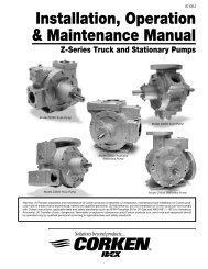
<strong>LPG</strong>C100A<br />
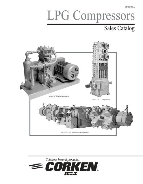
<strong>LPG</strong> <strong>Compressors</strong><br />
<strong>Sales</strong> <strong>Catalog</strong><br />
491-107 <strong>LPG</strong> Compressor<br />
D891 <strong>LPG</strong> Compressor<br />
HG601 <strong>LPG</strong> Horizontal Compressor
A Unit of IDEX Corporation<br />
<strong>LPG</strong> <strong>Compressors</strong><br />
Table of Contents<br />
General In<strong>for</strong>mation<br />
What is a <strong>Corken</strong> <strong>LPG</strong>/NH 3<br />
Compressor ..................................................................................................... 3<br />
Features and Benefits .................................................................................................................................... 4<br />
Markets Served ............................................................................................................................................. 5<br />
Liquid Transfer/Vapor Recovery .................................................................................................................. 5<br />
Features, Operating & Materials Specifications<br />
Vertical Single-Acting <strong>Compressors</strong> (Models 91–691) ............................................................................... 8<br />
Vertical Double-Acting <strong>Compressors</strong> (Model D891) ................................................................................ 10<br />
Horizontal <strong>Compressors</strong> (Models HG601AA–HG601EE)........................................................................ 12<br />
Compressor Selection<br />
How to Select a Vertical Compressor ......................................................................................................... 14<br />
Sample Liquid Transfer/Vapor Recovery (LTVR) Worksheet .......................................................... 15 & 16<br />
Butane, <strong>LPG</strong> and NH 3<br />
Quick Selection Charts .......................................................................................... 19<br />
Model Number Identification Codes<br />
Vertical Single-Acting <strong>Compressors</strong> (Models 91–691) ............................................................................. 23<br />
Vertical Double-Acting <strong>Compressors</strong> (Model D891) ................................................................................ 24<br />
Horizontal <strong>Compressors</strong> (Models HG601AA–HG601EE)........................................................................ 25<br />
Outline Dimensions<br />
Vertical Single-Acting <strong>Compressors</strong> (Models 91–691) ............................................................................. 26<br />
Vertical Double-Acting <strong>Compressors</strong> (Model D891) ................................................................................ 33<br />
Horizontal <strong>Compressors</strong> (Models HG601AA–HG601EE) ....................................................................... 37<br />
2
A Unit of IDEX Corporation<br />
What is a <strong>Corken</strong> <strong>LPG</strong> Compressor?<br />
<strong>Corken</strong> <strong>LPG</strong> gas compressors are part of the reciprocating compressor<br />
family. Reciprocating compressors pull vapor into a cylinder through a<br />
suction valve by drawing back a piston to create a low pressure area in<br />
the cylinder. They pressurize the gas by pushing the piston back up into<br />
the cylinder to squeeze the gas out through the discharge valve. Figure<br />
1, page 4 shows a cutaway view of an <strong>LPG</strong> gas compressor.<br />
A compressor valve consists of four parts: a seat, bumper, disc and spring.<br />
The spring rests against a bumper and pushes the disc against the seat.<br />
The disc seals off the flow passage through the seat. If more pressure<br />
builds up on the seat side than the bumper side, the disc will be <strong>for</strong>ced<br />
away from the seat and gas will flow through the valve, see figure 2,<br />
page 6. The suction valves are also equipped with a small ball and spring<br />
relief valve which is designed to relieve any condensation that takes<br />
place within the compressor cylinder. The liquid relief valve is not<br />
intended to relieve liquid that enters the cylinder through the suction<br />
valve. This liquid would be handled by a liquid trap.<br />
<strong>LPG</strong> <strong>Compressors</strong><br />
General In<strong>for</strong>mation<br />
<strong>LPG</strong>/NH 3<br />
<strong>Compressors</strong><br />
Reciprocating<br />
Piston type<br />
Single packed<br />
High reliability<br />
Easy maintenance<br />
Vertical and horizontal machines<br />
Single and double acting compression<br />
Bulk transfer<br />
Liquid transfer vapor recovery<br />
Flow range: 4 (6.8) – 414 cfm (703.5 m 3 /hr)<br />
Driver range: 7.5 (5.6) –75 hp (55.9 kW)<br />
In order <strong>for</strong> compression to take place, the piston must be sealed against<br />
the cylinder wall. This seal is made with several piston rings. Since <strong>LPG</strong><br />
Connections: NPT or 300# ANSI<br />
compressors must not be contaiminated by lubricating oils, the piston<br />
ring must be made of a self lubricating material. <strong>Corken</strong> standard piston rings are made of glass-filled PTFE. Gas pressure in the<br />
cylinder is used to press the piston rings against the cylinder wall, see figure 3, page 6. Ring expanders are used to push the rings<br />
towards the cylinder wall so high pressure gas may flow behind the rings.<br />
Piston rings <strong>for</strong>m a good dynamic seal but they are not tight enough to seal all the pressure and gas inside the cylinder; an<br />
additional seal is required to do this. This seal is the piston rod packing. The piston rod packing is a seal that is located at the<br />
bottom of the cylinder. It is composed of several parts, the most important being the self-lubricating PTFE V-rings that tightly seal<br />
against the piston rod. A spring is included in the packing assembly which allows a slight amount of “float” to reduce friction. The<br />
rod packing also seals oil in the crancase out of the compression chamber to prevent contamination of the gas.<br />
<strong>Corken</strong> standard <strong>LPG</strong> and NH 3<br />
comrpessors contain one set of piston rod packing per rod. The compressor line is sometimes<br />
refered to as single packed or plain style. One set of packing controls leakage and oil contamination of the vapor to a satisfactory<br />
level <strong>for</strong> most commercial <strong>LPG</strong>/NH 3<br />
applications. When leakage and contamination must be held to an absolute minimum, two or<br />
three packings sets separated by a distance piece may be utilized. See our I-Series Industrial Compressor sales brochure (Item<br />
I100) <strong>for</strong> more in<strong>for</strong>mation on these double (D-style) and tripple (T-style) packed gas compressors.<br />
The crankcase, connecting rod and crosshead, convert rotary motion from the motor to reciprocating motion at the pistion. All<br />
<strong>Corken</strong> compressors, except the model 91, use an oil pump to pressure lubricate the bearings and wrist pins to assure long service<br />
life. The oil pump is a gear type that may be run in either direction; <strong>for</strong> this reason <strong>Corken</strong> compressors may be run in<br />
either direction.<br />
3
A Unit of IDEX Corporation<br />
Features and Benefits<br />
<strong>LPG</strong> <strong>Compressors</strong><br />
General In<strong>for</strong>mation<br />
Threaded and ANSI flanges:<br />
<strong>Compressors</strong> are available in either threaded<br />
NPT, ANSI, or DIN flanged connections.<br />
High-efficiency valves:<br />
<strong>Corken</strong> valves offer quiet operation and<br />
high durability in oil-free gas<br />
applications. Specially designed suction<br />
valves which tolerate small amounts of<br />
condensate are available.<br />
O-ring head gaskets:<br />
Easy to install O-ring head gaskets<br />
providing highly reliable seals.<br />
Ductile-iron construction:<br />
All cylinders and heads are ductile iron<br />
<strong>for</strong> maximum thermal shock endurance.<br />
Self-lubricating PTFE piston rings:<br />
<strong>Corken</strong> provides a variety of state-ofthe-art<br />
piston ring designs to provide the<br />
most cost-effective operation of<br />
compressors <strong>for</strong> non-lube service. The<br />
step-cut design provides higher<br />
efficiencies during the entire life of the<br />
piston ring.<br />
Positively locked piston:<br />
Simple piston design allows end clearance to<br />
be precisely set to provide maximum<br />
efficiency and long life.<br />
Self-lubricating piston rod seals:<br />
Seals constructed of PTFE incorporating special<br />
fillers to ensure no oil carry over and maximize<br />
leakage control. Spring loaded seal design self<br />
adjusts to compensate <strong>for</strong> normal wear.<br />
Nitride-coated piston rods:<br />
Impregnated nitride coating provides superior<br />
corrosion and wear resistance.<br />
Cast-iron crosshead:<br />
Durable cast-iron crossheads provide superior<br />
resistance to corrosion and galling.<br />
Pressure-lubricated crankcase with filter:<br />
Self-reversing oil pump ensures proper lubrication<br />
regardless of directional rotation to main and connecting<br />
rod bearings. Standard 10-micron filter ensures long-lasting<br />
bearing life (not available on Model 91).<br />
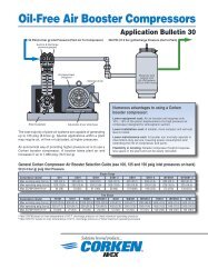
Model F291 Compressor<br />
Figure 1<br />
4
A Unit of IDEX Corporation<br />
Markets Served by <strong>Corken</strong> <strong>LPG</strong> <strong>Compressors</strong><br />
<strong>LPG</strong> <strong>Compressors</strong><br />
<strong>Corken</strong> <strong>LPG</strong> gas compressors are designed <strong>for</strong> use in liquid tranfer, vapor recovery, scavenger applications, tank evaucations and<br />
portable applications <strong>for</strong> the <strong>LPG</strong> and agricultural ammonia industries. Whether it is gas recovery from cylinders or barge unloading,<br />
<strong>Corken</strong> has a compressor <strong>for</strong> your application. Our compressors are also used in many industrial applications with a few<br />
modifications to the compressor packing arangement. Contact the factory <strong>for</strong> in<strong>for</strong>mation on moving gases other than<br />
<strong>LPG</strong> and NH 3<br />
.<br />
Liquid Transfer/Vapor Recovery<br />
General In<strong>for</strong>mation<br />
The most flexible method <strong>for</strong> moving liquid propane, butane and ammonia is with a compressor, a device designed to handle<br />
vapor and vapor only. How is this done? Any fluid, vapor or gas, may be moved by creating a different pressure between two<br />
points. A compressor may be used to create a pressure difference between the vapor spaces of two tanks. If the liquid spaces of the<br />
two tanks are connected, the pressure difference exerted by the vapor will cause the liquid to begin flowing from the higher<br />
pressure tank to the lower pressure tank (see figure 4, page 7).<br />
Changes in internal pressure of a propane tank will result in condensation and boiling. Condensation and boiling will tend to<br />
negate the pressure difference created by the compressor. Liquid transfer using a compressor works because vapor may be moved<br />
more quickly that it boils off and condenses. The flow rate induced will equal the volume of gas discharged from the compressor<br />
if a large enough compressor is chosen to make the effect of boiling and condensation negligible. The pressure increase through<br />
the compressor will equal the pressure decrease due to friction in the liquid piping. Years of experience have shown that piping<br />
designed to create a pressure drop of 30 psi or less works best. Higher pressure drops result in more condensation and boiling and<br />
reduce the flow rates due to reduced discharge volume.<br />
<strong>Compressors</strong> may also be used to evacuate tanks. High pressure propane vapor in a large tank has substantial economic value that<br />
makes it worth recovering. Tanks that must be unloaded through a dip tube (such as most railcars) leave a small liquid heel in the<br />
tank when liquid transfer is complete. A compressor can be used to reduce the pressure in the tank to boil the heel into recoverable<br />
vapor. The vapor recondenses when it is fed into the liquid section of another propane tank (see figure 5, page 7).<br />
<strong>Corken</strong> <strong>LPG</strong> transfer compressors are the standard of the industry. Models 91, 291 and 491 are popular <strong>for</strong> truck and small railcar<br />
unloading. The model 691 is suitable <strong>for</strong> unloading large railcars. <strong>Corken</strong> horizontal compressors and the vertical double-acting<br />
D891 compressor are used <strong>for</strong> unloading barges or several railcars at a time.<br />
Refer to the “Compressor Selection” section on page 14 of this sales catalog to determine the correct compressor <strong>for</strong> your application.<br />
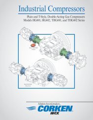
Four-way valve<br />
Compressor<br />
Liquid trap<br />
Strainer<br />
Belt guard<br />
Motor<br />
Primary Markets<br />
<strong>LPG</strong> bulk transfer<br />
Tank evacuation<br />
Vapor recovery<br />
Barge unloading<br />
Tank/railcar unloading<br />
Agricultural ammonia<br />
Model 491-107 compressor<br />
5
A Unit of IDEX Corporation<br />
<strong>LPG</strong> <strong>Compressors</strong><br />
General In<strong>for</strong>mation<br />
Figure 2<br />
Figure 3<br />
6
A Unit of IDEX Corporation<br />
Liquid Transfer<br />
<strong>LPG</strong> <strong>Compressors</strong><br />
General In<strong>for</strong>mation<br />
Vapor Recovery<br />
Figure 4<br />
Figure 5<br />
7
A Unit of IDEX Corporation<br />
<strong>LPG</strong> <strong>Compressors</strong><br />
Vertical Single-Acting Compressor Features & Specifications<br />
Models 91– 691<br />
Equipment Type & Options<br />
Single-acting, vertical, reciprocating piston type vapor compressor<br />
Single packed rod (D- & T-styles optional)<br />
NPT or 300# ANSI connections<br />
Applications<br />
Bulk transfer<br />
Vapor recovery<br />
Tank evacuation<br />
Gas scavenger<br />
Features & Benefits<br />
Self-lubricating piston rings:<br />
NPT or 300# ANSI connections:<br />
Multiple mounting configurations:<br />
High efficiency valves:<br />
Reversible oil pump:<br />
Simplified top down design:<br />
Non-lubricated operation to minimize oil in gas<br />
Versatility <strong>for</strong> your application<br />
Versatility <strong>for</strong> your application<br />
Quiet, reliable operation<br />
Allows operation in either direction<br />
Routine maintenance is minimally invasive<br />
Operating Specifications<br />
Model 91 291 491 691<br />
Specifications<br />
Bore of cylinder inches (mm) 3.0 (76.2) 3.0 (76.2) 4.0 (101.6) 4.5 (114.3)<br />
Stroke inches (mm) 2.5 (63.5) 2.5 (63.5) 3.0 (76.2) 4.0 (101.6)<br />
Piston displacement cfm (m 3 /hr)<br />
minimum @ 400 RPM 4.0 (6.8) 8.0 (13.06) 17.2 (29.2) 29.2 (49.6)<br />
maximum @ 825 RPM 8.3 (14.1) 16.5 (28.0) 35.5 (60.3) 60.2 (102.3)<br />
Maximum working pressure psig (bar g) 1 335 (23.1)<br />
Maximum brake horesepower (kW) 7.5 (5.6) 15 (11) 15 (11) 35 (26.1)<br />
Maximum rod load lb (kg) 3,600 (1,632.9) 3,600 (1,632.9) 4,000 (1,814.4) 5,500 (2,494.8)<br />
Maximum outlet temperature °F (°C) 350 (177)<br />
Bare unit weight lb (kg) 115 (52.2) 160 (72.6) 260 (117.9) 625 (283.5)<br />
Maximum flow—propane gpm (m 3 /hr) 50 (11.4) 101 (22.9) 215 (48.8) 361 (82.0)<br />
1<br />
These numbers specify pressure-containing abilities of the compressor cylinder and head. For many applications, factors other than the pressure rating will limit<br />
the maximum allowable discharge pressure to lower values. These factors include horsepower, temperature and rod load.<br />
8
A Unit of IDEX Corporation<br />
<strong>LPG</strong> <strong>Compressors</strong><br />
Vertical Single-Acting Compressor Features & Specifications<br />
Models 91–691 Material Specifications<br />
Part Model Standard Material Optional Material<br />
Head, cylinder All Ductile iron ASTM A536<br />
Crosshead guide,<br />
crankcase, flywheel, All Gray iron ASTM A48, Class 30<br />
bearing carrier<br />
Flange 691 Ductile iron ASTM A536<br />
91, 291 17-4 PH stainless steel<br />
Valve seat & bumper 491 Ductile iron ASTM A536<br />
691 17-4 PH stainless steel<br />
91, 291 410 stainless steel<br />
Valve plate 491 17-7 PH stainless steel<br />
691 410 Stainless Steel<br />
Valve spring<br />
91, 291, 691 17-7 PH stainless steel<br />
491 Inconel<br />
Valve gaskets All Soft aluminum<br />
Piston All Gray iron ASTM A48, Class 30<br />
Piston rod All 1045 steel Nitrotec coated<br />
Crosshead All Gray iron ASTM 48, Class 30<br />
Piston rings All PTFE, glass and moly filled<br />
Ring expanders All 302 stainless steel<br />
Packing cartridge, All<br />
connecting rod<br />
Ductile iron ASTM A536<br />
Packing (V-ring)<br />
91, 291, 491 PTFE, glass and moly filled<br />
691 Filled rein<strong>for</strong>ced PTFE<br />
Crankshaft All Ductile iron ASTM A536<br />
Con. rod bearing All Bimetal D-2 Babbit<br />
Wrist pin All C1018 steel<br />
Wrist pin busing All Bronze SAE J461<br />
Main bearing All Tapered roller<br />
Inspection plate All Aluminum<br />
O-rings All Buna-N Neoprene® 1<br />
Retainer rings All Steel<br />
Misc. gaskets All Coroprene<br />
1<br />
Registered trademark of the DuPont company.<br />
9
A Unit of IDEX Corporation<br />
<strong>LPG</strong> <strong>Compressors</strong><br />
Vertical Double-Acting Compressor Features & Specifications<br />
Model D891<br />
Equipment Type & Options<br />
Double-acting, vertical, reciprocating<br />
piston type vapor compressor<br />
Double packed rod<br />
Slip-on weld connections<br />
Applications<br />
Bulk transfer<br />
Truck, tank, railcar, barge unloading<br />
LTVR and scavenger applications<br />
Emergency evacuation<br />
Features & Benefits<br />
Self-lubricating piston rings:<br />
Multiple materials and configurations:<br />
Multiple mounting configurations:<br />
High efficiency valves:<br />
Reversible oil pump:<br />
Simplified top down design:<br />
Non-lubricated operation to minimize oil in gas<br />
Versatility <strong>for</strong> your application<br />
Versatility <strong>for</strong> your application<br />
Quiet, reliable operation<br />
Allows operation in either direction<br />
Routine maintenance is minimally invasive<br />
Operating Specifications<br />
Bore of cylinder inches (mm) 4.5 (113)<br />
Stroke inches (mm) 4.0 (101.6)<br />
Piston displacement cfm (m 3 /hr)<br />
minimum @ 400 RPM 56.6 (96.2)<br />
maximum @ 825 RPM 113.2 (192.0)<br />
Maximum working pressure psig (bar g) 465 (32.1)<br />
Maximum brake horesepower (kW) 45 (34)<br />
Maximum rod load lb (kg) 7,000 (3,175.2)<br />
Maximum outlet temperature °F (°C) 350 (177)<br />
Bare unit weight lb (kg) 855 (387.8)<br />
Maximum flow—propane gpm (m 3 /hr) 694 (157.6)<br />
10
A Unit of IDEX Corporation<br />
<strong>LPG</strong> <strong>Compressors</strong><br />
Vertical Double-Acting Compressor Features & Specifications<br />
Model D891 Material Specifications<br />
Part Standard Material Optional Material<br />
Head, cylinder and cylinder cap Ductile iron ASTM A536<br />
Crosshead guide<br />
Crankcase, flywheel Gray iron ASTM A48, Class 30<br />
Bearing carrier<br />
Flange<br />
ASTM A36 carbon steel<br />
Valve seat, bumper<br />
17-7 PH stainless steel<br />
Valve plate<br />
410 stainless steel<br />
Valve spring<br />
17-7 PH stainless steel<br />
Valve gaskets<br />
Soft aluminum<br />
Piston<br />
Ductile iron ASTM A536<br />
Piston rod<br />
1045 steel, Nitrotec<br />
Crosshead<br />
Ductile iron ASTM A536<br />
Piston rings<br />
PTFE, glass and moly filled<br />
Piston ring expanders<br />
302 stainless steel<br />
Packing cartridge and barrel<br />
Connecting rod<br />
Ductile iron ASTM A536<br />
Segmented packing rings Carbon-filled PTFE<br />
V-ring packing<br />
Filled rein<strong>for</strong>ced PTFE<br />
Crankshaft<br />
Ductile iron ASTM A536<br />
Connecting rod bearing<br />
Bimetal SAE 12 Babbit<br />
Wrist pin<br />
C1018 Steel or equivalent<br />
Wrist pin bushing<br />
Bronze SAE J461<br />
Main bearing<br />
Tapered roller<br />
Inspection plate<br />
Aluminum<br />
O-rings Buna-N Neoprene® 1<br />
Retainer rings<br />
Carbon steel<br />
Miscellaneous gaskets<br />
Rubber compositions<br />
1 Registered trademark of the DuPont company.<br />
11
A Unit of IDEX Corporation<br />
<strong>LPG</strong> <strong>Compressors</strong><br />
Horizontal Compressor Features & Specifications<br />
All Models HG601<br />
Equipment Type & Options<br />
Single or double acting<br />
Horizontal reciprocating piston compressor<br />
Pressure and oil wiper packing<br />
Slip-on weld connections<br />
Applications<br />
Bulk transfer<br />
Truck, tank, barge, railcar unloading<br />
Liquid Transfer/Vapor Recovery (LTVR)<br />
Features & Benefits<br />
Modular design:<br />
Multiple materials and configurations:<br />
Multiple mounting configurations:<br />
High efficiency valves:<br />
Lubricated and non-lube designs:<br />
Single or double acting<br />
Versatility <strong>for</strong> your application<br />
Versatility <strong>for</strong> your application<br />
Quiet, reliable operation<br />
Versatility <strong>for</strong> your application<br />
Operating Specifications<br />
Double Cylinder Models (single or double acting)<br />
Model HG601AA HG601BB HG601CC HG601DD HG601EE<br />
Specifications<br />
Bore of cylinders inches (mm) 8 (203.2) 6 (152.4) 5 (127) 4 (101.6) 3.25 (82.6)<br />
Stroke inches (mm) 3.0 (76.2)<br />
Piston displacement cfm (m 3 /hr)<br />
minimum @ 100 RPM 34.8 (58.6) 19.2 (32.7) 13.2 (22.4) 8.3 (14.1) 5.3 (9.1)<br />
maximum @ 1,200 RPM 414.0 (703.5) 231.0 (392.5) 158.4 (268.8) 99.6 (169.2) 64.0 (108.7)<br />
Maximum working pressure psig (bar g) 315.0 (21.7) 365.0 (25.2) 750 (51.7) 1,015.0 (7.0) 1,215.0 (83.8)<br />
Maximum brake horesepower (kW) 75 (55.9)<br />
Maximum rod load lb (kg) 7,000 (3,175.2)<br />
Maximum outlet temperature °F (°C) 350 (176.7)<br />
Approximate weight lb (kg) 1,070 (485.3) 910(412.8) 890 (403.7) 870 (394.6) 845 (383.3)<br />
Speed range<br />
400–1,200 RPM<br />
12
A Unit of IDEX Corporation<br />
<strong>LPG</strong> <strong>Compressors</strong><br />
Horizontal Compressor Features & Specifications<br />
All Models HG601 Material Specifications<br />
Part Model Standard Material Optional Material<br />
Crankcase<br />
All<br />
Adapters<br />
All<br />
Ductile Iron ASTM A538<br />
Cylinders<br />
All<br />
Grade 65-45-12<br />
Cylinder heads<br />
All<br />
Valve caps<br />
All<br />
Crankcase bearing carrier All Gray iron ASTM A48, Class 30<br />
Flanges All Steel slip-on welded<br />
Valve guard All Stainless steel<br />
Valve seat<br />
4", 5" Steel 4140<br />
3-1/4", 6", 8" Stainless steel<br />
Valve plates & springs All Stainless steel<br />
Valve gaskets<br />
3-1/4", 4", 5" Steel<br />
6", 8" Soft aluminum<br />
Pistons<br />
3-1/4", 4", 5" Steel<br />
6", 8" Ductile Iron, A536 Grade 65-45-12<br />
Piston rod All 1045 Steel Nitrotec treated<br />
Crosshead All Gray iron ASTM A48, Class 30<br />
Connecting rod &<br />
Ductile iron ASTM A536<br />
All<br />
packing cartridge grade 65-45-12<br />
Piston rings All PTFE, glass & moly filled<br />
Rider rings All PTFE, glass & moly filled<br />
Segmented packing rings<br />
4", 5" Carbon-filled PTFE<br />
3-1/4", 6", 8" Carbon-filled PTFE<br />
Segmented wiper rings<br />
4", 5" Brass<br />
3-1/4", 6", 8" PTFE, carbon filled<br />
Connecting rod bearings All Bimetal SAE 12 Babbit<br />
Crankshaft<br />
All<br />
Ductile iron ASTM A536<br />
grade 80-55-06<br />
Wrist pin All C-1018 steel<br />
Wrist pin bushing All Bronze SAE J461<br />
Main bearings All Tapered roller<br />
Inspection plate All Carbon steel<br />
O-rings All Buna-N Neoprene® 1<br />
Retainer rings All Carbon steel<br />
Lubricator tubing Lube models Steel<br />
1 Registered trademark of the DuPont company.<br />
13
A Unit of IDEX Corporation<br />
<strong>LPG</strong> <strong>Compressors</strong><br />
Compressor Selection<br />
How to Select a Vertical Compressor?<br />
Compressor size and speed selection is a highly inexact process with complex interactions of a number of different variables such<br />
as ambient temperature, pressure drops in liquid lines and vapor suction lines, solar radiation, precipitation, size of the tank and<br />
the surface area of the tank and piping. With this many variables, the exact per<strong>for</strong>mance of the compressor cannot be precisely<br />
calculated. <strong>Corken</strong>’s compressor selection tables are a quick and easy method to make an approximate selection <strong>for</strong> butane,<br />
propane and ammonia compressors. These charts show flows <strong>for</strong> different <strong>Corken</strong> compressors run at common speeds with a<br />
maximum tank temperature of 100°F and 80°F with a 30 psi pressure drop in the piping. In only the most extreme temperature<br />
conditions will tank temperature exceed 100°F. A large tank heats up and cools down much more slowly than the surrounding<br />
atmosphere. Although temperatures may frequently exceed 100°F on hot summer afternoons, tank temperatures will seldom rise<br />
this high. There<strong>for</strong>e, the horsepower values shown in the charts are very conservative and may be lowered <strong>for</strong> milder climates.<br />
Your local <strong>Corken</strong> distributor is usually the best source of in<strong>for</strong>mation <strong>for</strong> ideal motor sizes <strong>for</strong> the climate in your region. <strong>Corken</strong><br />
can also supply a computer analysis showing the horsepower required <strong>for</strong> different tank temperatures.<br />
If it is important that unloading operations be completed in a certain amount of time, a more complex analysis is required. When<br />
such an analysis is needed, or if a product other than butane, propane or ammonia is used, contact <strong>Corken</strong> so an application<br />
engineer (AE) may thoroughly review the situation. The application engineer will provide you with a printout of the analysis as<br />
shown in figure 6, page 16. This analysis is divided into three parts that clearly demonstrate how temperature affects flow rates<br />
and vapor recovery times.<br />
The highest liquid flow rates are achieved on hot days, see figure 7, page 17. This is because the pressure drop in the piping<br />
remains relatively constant as the temperature changes, while the vapor pressure swings over a wide range. The vapor pressure of<br />
propane is 38 psia at 0°F and 215 psia at 110°F. The discharge pressure, P2 is the product vapor pressure plus the system differential<br />
pressure. In figure 6, page 16 the 30 psi pressure drop is added to the vapor pressure to yield the discharge pressure shown in<br />
column P2. You will notice that the compression ratio (the absolute inlet vapor pressure divided by the absolute discharge pressure)<br />
rises as the temperature falls. As the compression ratio rises with falling temperature, the gas passing through the compressor is<br />
reduced, the amount of liquid displaced by the vapor is also reduced.<br />
When the liquid in a tank is unloaded through a dip tube, liquid transfer will cease when the liquid level falls beneath the bottom<br />
of this tube. The residual puddle is called a “liquid heel”. By reversing the direction of vapor flow and blocking the liquid line as<br />
shown in the section on liquid transfer/vapor recovery (LTVR), liquid may be recovered. By withdrawing vapor from the tank, the<br />
liquid will begin to boil into vapor to replace that which is being removed. This process is called “boil-off”. Boil-off is completed<br />
most rapidly on hot days, see figure 8, page 17. The high vapor pressure on hot days gives the gas a higher density than on cold<br />
days. It takes a larger quantity of liquid to replace a cubic foot of high density vapor than low density vapor.<br />
When boil-off is completed a substantial amount of propane is left in the tank in a vapor state. This vapor is equivalent to a<br />
substantial amount of liquid propane of significant economic value. As a rule of thumb in the <strong>LPG</strong> industry, propane tank cars<br />
should be evacuated to 40 psia. Alternately, a final evacuation pressure of 25 to 30% of original tank car pressure is a good value<br />
<strong>for</strong> most any liquefied gas. Evacuation pressures lower than this may not pay <strong>for</strong> the energy required to run the compressor and<br />
generally should not be considered unless factors other than economics are being considered. The vapor recovery procedure<br />
requires the most time on hot days because the high initial vapor pressure requires more time to reduce, see figure 9, page 18. The<br />
recovered vapor should be bubbled up through the liquid section of the receiver tank to recondense the vapor to liquid. The<br />
maximum horsepower requirement <strong>for</strong> the compressor occurs when the tank has been evacuated to approximately 50% of full<br />
vapor pressure, see figure 10, page 18. Larger motors are required to do vapor recovery in hot climates.<br />
14
A Unit of IDEX Corporation<br />
<strong>LPG</strong> <strong>Compressors</strong><br />
Definitions of Column Headings <strong>for</strong> Liquefied Gas Transfer Compressor Worksheet on Page 16<br />
Liquid Transfer and Boil-Off Phase<br />
T1<br />
VP<br />
P2<br />
T2<br />
CR<br />
VE<br />
Gpm<br />
Acfm (in)<br />
Acfm (out)<br />
Bhp<br />
Time<br />
Lb/hr<br />
Z (in)<br />
Z (out)<br />
Inlet temperature of gas, degrees Fahrenheit<br />
Vapor pressure, psia<br />
Discharge pressure, psia (vapor pressure + liquid line pressure drop)<br />
Discharge temperature of gas, degrees Fahrenheit<br />
Compression ratio (P2/P1)<br />
Volumetric efficiency<br />
Induced liquid flow rate, gallons per minute<br />
Volume flow rate of gas at inlet, actual cubic feet per minute<br />
Volume flow rate of gas at discharge, actual cubic feet per minute<br />
Brake horsepower<br />
Time to empty tank of liquid, minutes<br />
Mass flow rate of liquid, pounds per hour<br />
Compressibility factor at inlet<br />
Compressibility factor at discharge<br />
Vapor Recovery Phase<br />
T1<br />
Inlet temperature of gas, degrees Fahrenheit<br />
VP<br />
Vapor pressure, psia<br />
P2<br />
Discharge pressure, psia (vapor pressure + vapor line pressure drop)<br />
T2<br />
Discharge temperature of gas, degrees Fahrenheit<br />
VE (initial)<br />
Volumetric efficiency at beginning of vapor recovery phase (inlet pressure = vapor pressure)<br />
VE (final)<br />
Volumetric efficiency at end of vapor recovery phase (inlet pressure = desired evacuation<br />
pressure or where VE = 0, whichever comes first)<br />
Acfm (initial) Volume flow rate at beginning of vapor recovery phase (inlet pressure = vapor pressure)<br />
Acfm (final)<br />
Volume flow rate at end of vapor recovery phase (inlet pressure = desired evacuation<br />
pressure or where VE = 0, whichever comes first)<br />
Z (initial)<br />
Initial compressibility<br />
Z (final)<br />
Final compressibility<br />
Bhp<br />
Highest brake horsepower that occurs during vapor recovery<br />
P1 at VE = 0 Evacuation suction pressure when VE has fallen to 0 due to increase in compression ratio.<br />
P1 at max bhp Inlet pressure to compressor at the highest horsepower condition<br />
Time<br />
Time to complete evacuation of tank to desired evacuation pressure or to evacuate tank to<br />
point where VE falls to 0, whichever comes first-in minutes<br />
Equivalent Liquid The amount of liquid that would be <strong>for</strong>med by converting vapor in the tank to liquid<br />
A) Actual Equivalent amount of liquid of all the vapor in the tank<br />
B) Recovered Equivalent amount of liquid of vapor removed if tank is evacuated to desired<br />
evacuation pressure or until VE = 0, whichever comes first<br />
C) Claimable Equivalent amount of liquid of vapor removed if tank is evacuated until VE = 0<br />
Total Time<br />
Sum of time <strong>for</strong> liquid transfer phase and vapor recovery phase in hours<br />
15
A Unit of IDEX Corporation<br />
<strong>LPG</strong> <strong>Compressors</strong><br />
Compressor Selection<br />
Liquefied Gas Transfer Compressor Worksheet<br />
Model 691 Compressor on Propane<br />
N = 1.13; RPM = 825; PD = 60.7; MAWP = 265 psia; Critical pressure = 619 psia; critical temperature = 666°R<br />
Liquid Transfer Phase<br />
Tank volume = 33,000 gallons; 30 psi drop in liquid transfer system; molecular weight = 44.1; total liquid volume to be transferred = 29,618<br />
gallons or 89.8% of total tank volume<br />
T1 VP P2 T2 CR VE Gpm Acfm Acfm Bhp Time Lb/hour Z Z<br />
(°F) (psia) (psia) (°F) % (in) (out) (min) Liquid (in) (out)<br />
0 38 68 32 1.8 85 216 51.8 28.9 12.3 137 55,229 0.92 0.89<br />
10 46 76 38 1.7 87 238 52.7 31.9 13.1 124 60,864 0.91 0.88<br />
20 55 85 45 1.5 88 258 53.4 34.5 13.9 115 65,938 0.90 0.87<br />
30 66 96 52 1.5 89 278 54.0 37.1 14.8 107 70,841 0.89 0.86<br />
40 78 108 59 1.4 90 294 54.4 39.3 15.6 101 75,048 0.88 0.85<br />
50 92 122 67 1.3 90 309 54.8 41.3 16.6 96 78,903 0.86 0.83<br />
60 107 137 75 1.3 91 322 55.1 43.0 17.5 92 82,154 0.85 0.82<br />
70 124 154 83 1.2 91 333 55.3 44.6 18.5 89 85,064 0.83 0.80<br />
80 144 174 92 1.2 91 344 55.5 46.0 19.6 86 87,748 0.81 0.79<br />
90 165 195 101 1.2 92 353 55.7 47.1 20.7 84 89,966 0.80 0.77<br />
100 189 219 110 1.2 92 360 55.8 48.2 21.9 82 91,969 0.78 0.75<br />
110 215 245 119 1.1 92 367 55.9 49.1 23.2 81 93,687 0.76 0.73<br />
Boil-Off Phase<br />
Heel volume = 83 gallon liquid or 0.25% of total tank volume. 10 psi drop in vapor recovery system<br />
T1 V.P. P2 T2 CR VE bhp acfm Equiv. Vapor Liquid Recovery Time Z Z<br />
(°F) (psia) (psia) (°F) % (in) Volume (FT1) Rate (gpm) (min) (in) (out)<br />
0 38 48 13 1.3 92 9.4 55.8 955 5 17 0.92 0.91<br />
10 46 56 21 1.2 92 10.0 56.0 797 6 14 0.91 0.91<br />
20 55 65 29 1.2 93 10.5 56.2 673 7 12 0.90 0.89<br />
30 66 76 38 1.2 93 11.2 56.4 564 8 10 0.89 0.88<br />
40 78 88 47 1.1 93 11.9 56.5 480 10 8 0.88 0.87<br />
50 92 102 56 1.1 93 12.7 56.6 408 11 7 0.86 0.85<br />
60 107 117 65 1.1 93 13.5 56.7 352 13 6 0.85 0.84<br />
70 124 134 75 1.1 93 14.4 56.7 304 15 5 0.83 0.82<br />
80 144 154 84 1.1 93 15.4 56.8 261 18 5 0.81 0.81<br />
90 165 175 94 1.1 94 16.5 56.8 227 21 4 0.80 0.79<br />
100 189 199 103 1.1 94 17.6 56.8 197 24 3 0.78 0.77<br />
110 215 225 113 1.0 94 18.9 56.8 171 27 3 0.76 0.75<br />
Vapor Recovery Phase<br />
30 psia desired evacuation pressure 10 psia drop in vapor recovery system<br />
T1 V.P. P2 T2 VE (%) VE (%) acfm acfm Z in Z in bhp P1@ P1@ Time Equivalent Liquid (gallons) Total Time<br />
(°F) (psia) (psia) (°F) (initial) (final) (initial) (final) (initial) (final) (max) VE = 0 Max Bhp (min) Actual Recovered Claimable Hours<br />
0 38 48 20 92 90 55 54 0.92 0.93 10.2 5 26 19 381 89 337 2.9<br />
10 46 56 42 92 86 56 52 0.91 0.94 11.1 6 32 35 456 185 405 2.9<br />
20 55 65 64 93 82 56 49 0.90 0.95 12.1 6 34 50 540 288 482 2.9<br />
30 66 76 80 93 80 56 48 0.89 0.95 13.4 8 41 67 645 377 578 3.1<br />
40 78 88 103 93 75 56 45 0.88 0.95 14.8 9 48 84 758 506 682 3.2<br />
50 92 102 126 93 69 56 41 0.86 0.96 16.4 10 57 101 891 650 803 3.4<br />
60 107 117 143 93 66 56 40 0.85 0.96 18.1 12 60 118 1,034 781 937 3.6<br />
70 124 134 166 93 60 56 36 0.83 0.96 20.0 13 70 137 1,197 953 1,088 3.9<br />
80 144 154 188 93 53 56 32 0.81 0.96 22.3 15 82 158 1,395 1,153 1,272 4.1<br />
90 165 175 209 94 47 56 28 0.80 0.97 24.6 17 95 180 1,604 1,364 1,466 4.5<br />
100 189 199 234 94 37 56 22 0.78 0.97 27.3 20 99 206 1,850 1,619 1,695 4.0<br />
110 215 225 256 94 29 56 17 0.76 0.97 30.2 23 114 237 2,123 1,894 1,948 5.3<br />
Assumptions <strong>for</strong> calculations:<br />
1) Pressure drops remain constant<br />
2) Included flow based on isothermal compression<br />
3) Bhp and temperature are based on adiabatic compression<br />
4) Compressibility effects are considered in calculations<br />
5) Heat transfer is sufficient to maintain constant tank temperature during boilout<br />
Figure 6<br />
16
A Unit of IDEX Corporation<br />
Liquid Transfer Phase—Propane<br />
<strong>LPG</strong> <strong>Compressors</strong><br />
Compressor Selection<br />
Figure 7<br />
Boil-Out Phase—Propane<br />
Figure 8<br />
17
A Unit of IDEX Corporation<br />
Vapor Recovery Phase—Propane<br />
<strong>LPG</strong> <strong>Compressors</strong><br />
Compressor Selection<br />
Figure 9<br />
Vapor Recovery Phase—Propane<br />
Figure 10<br />
18
A Unit of IDEX Corporation<br />
Butane Compressor Selection Table<br />
19<br />
<strong>LPG</strong> <strong>Compressors</strong><br />
Compressor Selection<br />
Driver Horsepower<br />
Liquid<br />
Liquid<br />
Transfer Transfer<br />
&<br />
Without<br />
Residual Residual<br />
Driver Sheave Size Vapor Vapor Piping Size 3<br />
Capacity Displacement Compressor Pitch Diameter (inches) 2 Recovery Recovery<br />
Service gpm 1 cfm Model RPM 1,750 RPM 1,450 RPM 100°F 80°F 100°F 80°F Vapor Liquid<br />
13 4 91 400 A 3.0 A 3.6 3 3 3 3 3/4 1-1/4<br />
Small 17 5 91 505 A 3.8 B 4.6 3 3 3 3 3/4 1-1/4<br />
bulk 20 6 91 590 B 4.6 B 5.6 3 3 3 3 1 1-1/4<br />
plants 24 7 91 695 B 5.4 B 6.6 5 5 5 5 1 1-1/2<br />
23 7 290, 291 345 A 3.0 A 3.6 2 2 2 2 1 1-1/2<br />
27 8 91 795 B 6.2 B 7.4 5 5 5 5 1 1-1/2<br />
26 8 290, 291 390 A 3.4 B 4.0 2 2 2 2 1 1-1/2<br />
30 9 290, 291 435 A 3.8 B 4.6 3 3 3 3 1 1-1/2<br />
33 10 290, 291 490 B 4.4 B 5.2 3 3 3 3 1 2<br />
Unloading 36 11 290, 291 535 B 4.8 B 5.8 3 3 3 3 1 2<br />
single tank 39 12 290, 291 580 B 5.2 B 6.2 5 3 5 3 1 2<br />
car or 42 13 290, 291 625 B 5.6 B 6.6 5 5 5 5 1-1/4 2<br />
transport 47 14 290, 291 695 B 6.2 B 7.4 5 5 5 5 1-1/4 2<br />
50 15 290, 291 735 B 6.6 B 8.0 5 5 5 5 1-1/4 2-1/2<br />
50 15 490, 491 345 A 3.0 A 3.6 5 5 5 5 1-1/4 2-1/2<br />
53 16 290, 291 780 B 7.0 B 8.6 7-1/2 5 7-1/2 5 1-1/4 2-1/2<br />
53 16 490, 491 370 A 3.2 A 3.8 5 5 5 5 1-1/4 2-1/2<br />
56 17 490, 491 390 A 3.4 B 4.0 5 5 5 5 1-1/4 3<br />
60 18 490, 491 415 A 3.6 B 4.4 5 5 5 5 1-1/4 3<br />
63 19 490, 491 435 A 3.8 B 4.6 5 5 5 5 1-1/4 3<br />
65 20 490, 491 445 B 4.0 B 4.8 5 5 5 5 1-1/4 3<br />
68 21 490, 491 470 B 4.2 B 5.0 5 5 5 5 1-1/4 3<br />
Unloading 71 22 490, 491 490 B 4.4 B 5.2 7-1/2 5 7-1/2 5 1-1/4 3<br />
two or 75 23 490, 491 515 B 4.6 B 5.6 7-1/2 5 7-1/2 5 1-1/4 3<br />
more tank 77 24 490, 491 535 B 4.8 B 5.8 7-1/2 7-1/2 7-1/2 7-1/2 1-1/4 3<br />
cars at 81 25 490, 491 560 B 5.0 B 6.0 7-1/2 7-1/2 7-1/2 7-1/2 1-1/4 3<br />
one time 84 26 490, 491 580 B 5.2 B 6.2 7-1/2 7-1/2 7-1/2 7-1/2 1-1/4 3<br />
or large 87 27 490, 491 605 B 5.4 B 6.4 7-1/2 7-1/2 7-1/2 7-1/2 1-1/4 3<br />
transport 91 28 490, 491 625 B 5.6 B 6.6 7-1/2 7-1/2 7-1/2 7-1/2 1-1/2 3<br />
with excess 94 29 490, 491 650 B 5.8 B 7.0 10 7-1/2 10 7-1/2 1-1/2 3<br />
flow valves 97 30 490, 491 670 B 6.0 10 7-1/2 10 7-1/2 1-1/2 3<br />
of adequate 94 30 690, 691 400 B 4.4 B 5.2 7-1/2 7-1/2 7-1/2 7-1/2 1-1/2 3<br />
capacity 100 31 490, 491 695 B 6.2 B 7.4 10 7-1/2 10 7-1/2 1-1/2 3<br />
98 31 690, 691 420 B 4.6 B 5.6 10 7-1/2 10 7-1/2 1-1/2 3<br />
107 32 490, 491 740 B 6.6 B 8.0 10 10 10 10 1-1/2 3<br />
103 32 690, 691 440 B 4.8 B 5.8 10 7-1/2 10 7-1/2 1-1/2 3<br />
110 33 490, 491 760 B 6.8 B 8.0 10 10 10 10 1-1/2 3<br />
113 34 490, 491 780 B 7.0 B 8.6 10 10 10 10 1-1/2 3<br />
107 34 690, 691 455 B 5.0 B 6.0 10 10 10 10 1-1/2 3<br />
111 35 690, 691 475 B 5.2 B 6.2 10 10 10 10 1-1/2 3<br />
119 36 490, 491 825 B 7.4 B 8.6 15 10 15 10 1-1/2 3<br />
116 36 690, 691 495 B 5.4 A 6.4 10 10 10 10 1-1/2 3<br />
120 38 690, 691 510 B 5.6 B 6.8 10 10 10 10 1-1/2 4<br />
Unloading 124 39 690, 691 530 B 5.8 B 7.0 10 10 10 10 1-1/2 4<br />
large 129 41 690, 691 550 B 6.0 A 7.0 10 10 10 10 1-1/2 4<br />
tank cars, 133 42 690, 691 565 B 6.2 B 7.4 10 10 10 10 2 4<br />
multiple 137 43 690, 691 585 B 6.4 A 7.4 10 10 10 10 2 4<br />
vessels, 142 45 690, 691 605 B 6.6 B 8.0 15 10 15 10 2 4<br />
barges or 145 46 690, 691 620 B 6.8 15 10 15 10 2 4<br />
terminals 150 47 690, 691 640 B 7.0 A 8.2 15 10 15 10 2 4<br />
158 48 690, 691 675 B 7.4 B 8.6 15 15 15 15 2 4<br />
171 54 690, 691 730 B 8.0 B 9.4 15 15 15 15 2 4<br />
184 58 690, 691 785 B 8.6 15 15 15 15 2 4<br />
193 60 690, 691 820 TB 9.0 A 10.6 15 15 15 15 2 4<br />
260 82.1 D891 580 5V 7.1 5V 8.5 20 20 20 20 3 6<br />
359 113.3 D891 800 5V 9.75 5V 11.8 25 25 25 25 3 6<br />
1<br />
The capacities shown are based on 70 o F, but will vary dependingupon piping, fittings used, product being transferred and temperature. The factory can<br />
supply a detailed computer analysis if required.<br />
2<br />
Driver sheaves: 91 (2 belts); 290, 291, 490, 491 (3 belts); 690, 691 (4 belts).<br />
3<br />
The piping sizes shown are considered minimum. If the length exceeds 100 ft, use the next larger size.<br />
NOTE: Please consult factory <strong>for</strong> compressors with higher flows.
A Unit of IDEX Corporation<br />
Propane Compressor Selection Table<br />
<strong>LPG</strong> <strong>Compressors</strong><br />
Compressor Selection<br />
Driver Horsepower<br />
Liquid<br />
Liquid<br />
Transfer Transfer<br />
&<br />
Without<br />
Residual Residual<br />
Driver Sheave Size Vapor Vapor Piping Size 3<br />
Capacity Displacement Compressor Pitch Diameter (inches) 2 Recovery Recovery<br />
Service gpm 1 cfm Model RPM 1,750 RPM 1,450 RPM 100°F 80°F 100°F 80°F Vapor Liquid<br />
23 4 91 400 A 3.0 A 3.6 5 3 3 3 3/4 1-1/4<br />
Small 29 5 91 505 A 3.8 B 4.6 5 5 5 5 3/4 1-1/4<br />
bulk 34 6 91 590 B 4.6 B 5.6 5 5 5 5 1 1-1/4<br />
plants 40 7 91 695 B 5.4 B 6.6 5 5 5 5 1 1-1/2<br />
39 7 290, 291 345 A 3.0 A 3.6 3 3 3 3 1 1-1/2<br />
45 8 91 795 B 6.2 B 7.4 7-1/2 7-1/2 7-1/2 7-1/2 1 1-1/2<br />
44 8 290, 291 390 A 3.4 B 4.0 5 3 3 3 1 1-1/2<br />
50 9 290, 291 435 A 3.8 B 4.6 5 5 3 3 1 1-1/2<br />
56 10 290, 291 490 B 4.4 B 5.2 5 5 5 5 1 2<br />
Unloading 61 11 290, 291 535 B 4.8 B 5.8 5 5 5 5 1 2<br />
single tank 66 12 290, 291 580 B 5.2 B 6.2 7-1/2 5 5 5 1 2<br />
car or 71 13 290, 291 625 B 5.6 B 6.6 7-1/2 5 7-1/2 5 1-1/4 2<br />
transport 79 14 290, 291 695 B 6.2 B 7.4 7-1/2 7-1/2 7-1/2 7-1/2 1-1/4 2<br />
84 15 290, 291 735 B 6.6 B 8.0 10 7-1/2 10 7-1/2 1-1/4 2-1/2<br />
84 15 490, 491 345 A 3.0 A 3.6 7-1/2 7-1/2 5 5 1-1/4 2-1/2<br />
89 16 290, 291 780 B 7.0 B 8.6 10 10 10 10 1-1/4 2-1/2<br />
89 16 490, 491 370 A 3.2 A 3.8 7-1/2 7-1/2 7-1/2 5 1-1/4 2-1/2<br />
95 17 490, 491 390 A 3.4 B 4.0 7-1/2 7-1/2 7-1/2 7-1/2 1-1/4 3<br />
101 18 490, 491 415 A 3.6 B 4.4 10 7-1/2 7-1/2 7-1/2 1-1/4 3<br />
106 19 490, 491 435 A 3.8 B 4.6 10 7-1/2 7-1/2 7-1/2 1-1/4 3<br />
108 20 490, 491 445 B 4.0 B 4.8 10 7-1/2 7-1/2 7-1/2 1-1/4 3<br />
114 21 490, 491 470 B 4.2 B 5.0 10 7-1/2 7-1/2 7-1/2 1-1/4 3<br />
Unloading 119 22 490, 491 490 B 4.4 B 5.2 10 10 7-1/2 7-1/2 1-1/4 3<br />
two or 125 23 490, 491 515 B 4.6 B 5.6 10 10 10 7-1/2 1-1/4 3<br />
more tank 130 24 490, 491 535 B 4.8 B 5.8 15 10 10 10 1-1/4 3<br />
cars at 136 25 490, 491 560 B 5.0 B 6.0 15 10 10 10 1-1/4 3<br />
one time 141 26 490, 491 580 B 5.2 B 6.2 15 10 10 10 1-1/4 3<br />
or large 147 27 490, 491 605 B 5.4 B 6.4 15 10 15 10 1-1/4 3<br />
transport 152 28 490, 491 625 B 5.6 B 6.6 15 15 15 15 1-1/2 3<br />
with excess 158 29 490, 491 650 B 5.8 B 7.0 15 15 15 15 1-1/2 3<br />
flow valves 163 30 490, 491 670 B 6.0 15 15 15 15 1-1/2 3<br />
of adequate 163 30 690, 691 400 B 4.4 B 5.2 15 15 10 10 1-1/2 3<br />
capacity 168 31 490, 491 695 B 6.2 B 7.4 15 15 15 15 1-1/2 3<br />
171 31 690, 691 420 B 4.6 B 5.6 15 15 10 10 1-1/2 3<br />
179 32 490, 491 740 B 6.6 B 8.0 15 15 15 15 1-1/2 3<br />
178 32 690, 691 440 B 4.8 B 5.8 15 15 10 10 1-1/2 3<br />
186 34 690, 691 455 B 5.0 B 6.0 15 15 15 10 1-1/2 3<br />
193 35 690, 691 475 B 5.2 B 6.2 15 15 15 10 1-1/2 3<br />
200 36 690, 691 495 B 5.4 B 6.4 15 15 15 15 1-1/2 3<br />
208 38 690, 691 510 B 5.6 B 6.8 20 15 15 15 1-1/2 4<br />
215 39 690, 691 530 B 5.8 B 7.0 20 15 15 15 1-1/2 4<br />
223 41 690, 691 550 B 6.0 A 7.0 20 15 15 15 1-1/2 4<br />
230 42 690, 691 565 B 6.2 B 7.4 20 15 15 15 2 4<br />
Unloading 237 43 690, 691 585 B 6.4 A 7.4 20 15 15 15 2 4<br />
large 245 45 690, 691 605 B 6.6 B 8.0 20 15 15 15 2 4<br />
tank cars, 252 46 690, 691 620 B 6.8 20 20 15 15 2 4<br />
multiple 260 47 690, 691 640 B 7.0 A 8.2 20 20 20 15 2 4<br />
vessels, 275 48 690, 691 675 B 7.4 B 8.6 25 20 20 20 2 4<br />
barges or 297 54 690, 691 730 B 8.0 B 9.4 25 20 20 20 2 4<br />
terminals 319 58 690, 691 785 B 8.6 25 20 25 20 2 4<br />
334 60 690, 691 820 TB 9.0 A 10.6 30 25 25 20 2 4<br />
452 82 D891 580 5V 7.1 5V 8.5 30 30 30 30 3 6<br />
623 113 D891 800 5V 9.75 5V 11.8 40 40 30 3 6<br />
1<br />
The capacities shown are based on 70 o F, but will vary depending upon piping, fittings used, product being transferred and temperature. The factory can<br />
supply a detailed computer analysis if required.<br />
2<br />
Driver sheaves: 91 (2 belts); 290, 291, 490, 491 (3 belts); 690, 691 (4 belts).<br />
3<br />
The piping sizes shown are considered minimum. If the length exceeds 100 ft, use the next larger size.<br />
NOTE: Please consult factory <strong>for</strong> compressors with higher flows.<br />
20
A Unit of IDEX Corporation<br />
Ammonia Compressor Selection Table<br />
<strong>LPG</strong> <strong>Compressors</strong><br />
Compressor Selection<br />
Driver Horsepower<br />
Liquid<br />
Liquid<br />
Transfer Transfer<br />
&<br />
Without<br />
Residual Residual<br />
Driver Sheave Size Vapor Vapor Piping Size 3<br />
Capacity Displacment Compressor Pitch Diameter (inches) 2 Recovery Recovery<br />
Service gpm 1 cfm Model RPM 1,750 RPM 1,450 RPM 100°F 80°F 100°F 80°F Vapor Liquid<br />
23 4 91 400 A 3.0 A 3.6 5 3 3 3 3/4 1-1/4<br />
Small 29 5 91 505 A 3.8 B 4.6 5 5 5 3 3/4 1-1/4<br />
bulk 34 6 91 590 B 4.6 B 5.6 5 5 5 5 1 1-1/4<br />
plants 40 7 91 695 B 5.4 B 6.6 5 5 5 5 1 1-1/2<br />
43 7 290, 291 345 A 3.0 A 3.6 5 3 3 3 1 1-1/2<br />
46 8 91 795 B 6.2 B 7.4 7-1/2 5 5 5 1 1-1/2<br />
45 8 290, 291 390 A 3.4 B 4.0 5 3 3 3 1 1-1/2<br />
50 9 290, 291 435 A 3.8 B 4.6 5 5 3 3 1 1-1/2<br />
56 10 290, 291 490 B 4.4 B 5.2 5 5 5 3 1 2<br />
Unloading 62 11 290, 291 535 B 4.8 B 5.8 7-1/2 5 5 5 1 2<br />
single tank 67 12 290, 291 580 B 5.2 B 6.2 7-1/2 5 5 5 1 2<br />
car or 72 13 290, 291 625 B 5.6 B 6.6 7-1/2 5 5 5 1-1/4 2<br />
transport 80 14 290, 291 695 B 6.2 B 7.4 7-1/2 7-1/2 7-1/2 5 1-1/4 2<br />
85 15 290, 291 735 B 6.6 B 8.0 10 7-1/2 7-1/2 7-1/2 1-1/4 2-1/2<br />
85 15 490, 491 345 A 3.0 A 3.6 7-1/2 7-1/2 5 5 1-1/4 2-1/2<br />
90 16 290, 291 780 B 7.0 B 8.6 10 7-1/2 7-1/2 7-1/2 1-1/4 2-1/2<br />
90 16 490, 491 370 A 3.2 A 3.8 10 7-1/2 5 5 1-1/4 2-1/2<br />
96 17 490, 491 390 A 3.4 B 4.0 10 7-1/2 5 5 1-1/4 3<br />
102 18 490, 491 415 A 3.6 B 4.4 10 7-1/2 7-1/2 7-1/2 1-1/4 3<br />
107 19 490, 491 435 A 3.8 B 4.6 10 7-1/2 7-1/2 7-1/2 1-1/4 3<br />
110 20 490, 491 445 B 4.0 B 4.8 10 7-1/2 7-1/2 7-1/2 1-1/4 3<br />
115 21 490, 491 470 B 4.2 B 5.0 10 7-1/2 7-1/2 7-1/2 1-1/4 3<br />
Unloading 120 22 490, 491 490 B 4.4 B 5.2 15 10 7-1/2 7-1/2 1-1/4 3<br />
two or 126 23 490, 491 515 B 4.6 B 5.6 15 10 7-1/2 7-1/2 1-1/4 3<br />
more tank 131 24 490, 491 535 B 4.8 B 5.8 15 10 10 7-1/2 1-1/4 3<br />
cars at 138 25 490, 491 560 B 5.0 B 6.0 15 10 10 7-1/2 1-1/4 3<br />
one time 142 26 490, 491 580 B 5.2 B 6.2 15 10 10 7-1/2 1-1/4 3<br />
or large 148 27 490, 491 605 B 5.4 B 6.4 15 10 10 10 1-1/4 3<br />
transport 153 28 490, 491 625 B 5.6 B 6.6 15 10 10 10 1-1/2 3<br />
with excess 160 29 490, 491 650 B 5.8 B 7.0 15 15 10 10 1-1/2 3<br />
flow valves 165 30 490, 491 670 B 6.0 15 15 15 10 1-1/2 3<br />
of adequate 165 30 690, 691 400 B 4.4 B 5.2 15 15 10 10 1-1/2 3<br />
capacity 170 31 490, 491 695 B 6.2 B 7.4 15 15 15 10 1-1/2 3<br />
173 31 690, 691 420 B 4.6 B 5.6 15 15 10 10 1-1/2 3<br />
181 32 490, 491 740 B 6.6 B 8.0 15 15 15 15 1-1/2 3<br />
180 32 690, 691 440 B 4.8 B 5.8 15 15 10 10 1-1/2 3<br />
188 34 690, 691 455 B 5.0 B 6.0 20 15 10 10 1-1/2 3<br />
195 35 690, 691 475 B 5.2 B 6.2 20 15 10 10 1-1/2 3<br />
203 36 690, 691 495 B 5.4 B 6.4 20 15 15 10 1-1/2 3<br />
211 38 690, 691 510 B 5.6 B 6.8 20 15 15 10 1-1/2 4<br />
218 39 690, 691 530 B 5.8 B 7.0 20 15 15 15 1-1/2 4<br />
226 41 690, 691 550 B 6.0 A 7.0 20 15 15 15 1-1/2 4<br />
233 42 690, 691 565 B 6.2 B 7.4 20 15 15 15 2 4<br />
Unloading 240 43 690, 691 585 B 6.4 A 7.4 20 20 15 15 2 4<br />
large 248 45 690, 691 605 B 6.6 B 8.0 20 20 15 15 2 4<br />
tank cars, 255 45 690, 691 620 B 6.8 25 20 15 15 2 4<br />
multiple 263 47 690, 691 640 B 7.0 A 8.2 25 20 15 15 2 4<br />
vessels, 278 48 690, 691 675 B 7.4 B 8.6 25 20 15 15 2 4<br />
barges or 301 54 690, 691 730 B 8.0 B 9.4 25 20 20 15 2 4<br />
terminals 323 58 690, 691 785 B 8.6 30 25 20 20 2 4<br />
338 60 690, 691 820 TB 9.0 A 10.6 30 25 20 20 2 4<br />
459 82 D891 580 5V 7.1 5V 8.5 40 30 30 30 3 6<br />
633 113 D891 800 5V 9.75 5V 11.8 40 40 30 3 6<br />
1<br />
The capacities shown are based on 70 o F, but will vary depending upon piping, fittings used, product being transferred and temperature. The factory can<br />
supply a detailed computer analysis if required.<br />
2<br />
Driver sheaves: 91 (2 belts); 290, 291, 490, 491 (3 belts); 690, 691 (4 belts).<br />
3<br />
The piping sizes shown are considered minimum. If the length exceeds 100 ft, use the next larger size.<br />
NOTE: Please consult factory <strong>for</strong> compressors with higher flows.<br />
21
A Unit of IDEX Corporation<br />
Compressor Mounting Selections<br />
<strong>LPG</strong> <strong>Compressors</strong><br />
Compressor Selection<br />
Standard 107 Items<br />
Steel baseplate<br />
V-Belt drive<br />
Adjustable driver slide base<br />
Enclosed steel beltguard<br />
Suction and discharge pressure gauges<br />
40 Micron strainer<br />
Non-lube 4-way valve<br />
Interconnecting piping<br />
Liquid trap as specified below<br />
107 Mounting<br />
Mechanical liquid trap with ball float<br />
107A Mounting<br />
Automatic liquid trap with one NEMA 7<br />
liquid level switch<br />
107B Mounting<br />
Automatic liquid trap (ASME code) with two<br />
NEMA 7 liquid level switches<br />
Standard 109 Items<br />
Steel baseplate<br />
V-Belt drive<br />
Adjustable driver slide base<br />
Enclosed steel beltguard<br />
Suction and discharge pressure gauges<br />
Interconnecting piping<br />
Liquid trap as specified below<br />
109 Mounting<br />
Mechanical liquid trap with ball float<br />
109A Mounting<br />
Automatic liquid trap with one NEMA 7<br />
liquid level switch<br />
109B Mounting<br />
Automatic liquid trap (ASME code) with two<br />
NEMA 7 liquid level switches<br />
22
A Unit of IDEX Corporation<br />
<strong>LPG</strong> <strong>Compressors</strong><br />
Vertical Single-Acting Model Number Identification Code<br />
Base Model 91 291 491 691 Model Number<br />
Inlet 3/4" NPT 3/4" NPT 1-1/4" NPT 2" NPT Base X X X X X X X X X X<br />
Outlet 3/4" NPT 3/4" NPT 1-1/4" NPT 1-1/2" NPT<br />
Base Model F91 F291 F491 F691<br />
Inlet 3/4" ANSI 3/4" ANSI 1-1/4" ANSI 2" ANSI<br />
Outlet 3/4" ANSI 3/4" ANSI 1-1/4" ANSI 2" ANSI<br />
Packing Arrangement Pressurized inlet Standard A<br />
Crankcase Style<br />
Splash lubricated Standard N/A N/A N/A J<br />
Extended crankshaft Optional Optional Optional N/A E<br />
Pressure lubricated N/A Standard Standard Standard M<br />
Standard with heater N/A Optional Optional Optional MH<br />
Valves<br />
Liquid relief suction Standard 3<br />
Standard valves Optional 4<br />
Piston Rings and Packing PTFE Standard F<br />
Gasket Material Aluminum Standard B<br />
O-rings<br />
Buna-N Standard A<br />
Neoprene® 1 Optional B<br />
Intercooler None N/A <strong>for</strong> single stage compressor N<br />
14" flywheel used with<br />
extended crankshaft<br />
Optional N/A E<br />
Flywheel Heavy duty Optional Optional Optional Optional H<br />
No flywheel Optional N<br />
Standard flywheel Standard S<br />
Protective Coating No coating Standard N<br />
Piston Rod Coating Nitrotec Standard N<br />
1<br />
Registered trademark of the DuPont company.<br />
See page 24 <strong>for</strong> mounting options.<br />
23
<strong>LPG</strong> <strong>Compressors</strong><br />
A Unit of IDEX Corporation<br />
Vertical Double-Acting Model Number Identification Code<br />
Base Model Number D891 Model Number<br />
Inlet Connection 2" Weld Base X X X X X X X X X X<br />
Outlet Connection<br />
2" Weld<br />
Ship Weight (lb) 900<br />
Packing<br />
Arrangement<br />
Packing arranged <strong>for</strong> padding of distance piece Standard J<br />
Crankcase Pressure lubricated Standard M<br />
Style Standard with heater Optional MH<br />
Valves<br />
Standard suction and discharge valves Standard 4<br />
Suction valve unloaders Optional 9<br />
Piston Ring<br />
and Packing PTFE Standard F<br />
Material<br />
Gasket Material Aluminum Standard B<br />
O-ring Buna-N Standard A<br />
Material Neoprene® 1 Optional B<br />
Intercooler N/A <strong>for</strong> single stage compressor Standard N<br />
Flywheel<br />
No flywheel provided Optional N<br />
Standard flywheel Standard S<br />
Protective<br />
Coating<br />
None Standard N<br />
Piston Rod<br />
Coating<br />
Nitrotec Standard N<br />
1<br />
Registered trademark of the DuPont company.<br />
Mounting Options For Models 91– 891<br />
103 Mounting includes: Steel baseplate, adjustable driver slide base, V-belt drive and enclosed steel beltguard. Pressure gauges are<br />
mounted on the compressor. 3<br />
107 Mounting includes: Steel baseplate, mechanical liquid trap, non-lube 4-way valve, interconnecting piping, strainer, adjustable driver<br />
slide base, V-belt drive and enclosed steel beltguard. Pressure gauges are mounted on the compressor. 3<br />
107A Mounting includes: All items on the 107 replacing the mechanical float in the liquid trap with a NEMA 7 liquid level switch. 3<br />
107B Mounting includes: All items on the 107 replacing the liquid trap with a larger ASME code liquid trap with 2 NEMA 7 liquid level<br />
switches set <strong>for</strong> alarm and shutdown. 3<br />
107TR Mounting includes: All items on the 107 set up to be used as a transport unit. Note that the compressor must have the optional 14"<br />
flywheel and extended crankshaft to use this mounting. 2,3<br />
109 Mounting includes: Steel baseplate, mechanical liquid trap, interconnecting piping, adjustable driver slide base, V-belt drive and<br />
enclosed steel beltguard. Pressure gauges are mounted on the compressor. 3<br />
109A Mounting includes: All items on the 109 replacing the mechanical float in the liquid trap with a NEMA7 liquid level switch. 3<br />
109B Mounting includes: All items on the 109 replacing the liquid trap with a larger ASME code liquid trap with 2 NEMA 7 liquid level<br />
switches set <strong>for</strong> alarm and shutdown. 3<br />
109TR Mounting includes: All items on the 109 set up to be used as a transport unit. Note the compressor must have the optional 14"<br />
flywheel and extended crankshaft to use this mounting. 2,3<br />
2<br />
Not suitable <strong>for</strong> 691, D891 or horizontal models.<br />
3<br />
Discharge relief valves are required but not included in these mountings.<br />
24
<strong>LPG</strong> <strong>Compressors</strong><br />
A Unit of IDEX Corporation<br />
Horizontal Model Number Identification Code<br />
Base Model HG601AA HG601BB HG601CC HG601DD HG601EE HG601FF 1 Model Number<br />
Cylinders 8" x 8" 6" x 6" 5" x 5" 4" x 4" 3-1/4" x 3-1/4" 2-3/4" x 2-3/4" Base X X X X X X X X X X X<br />
Ship Wt (lb) 1,070 910 890 870 845 845<br />
Packing Standard Standard O<br />
Arrangement Purge Optional P<br />
Crankcase Pressure lube Standard M<br />
Style Std with heater Optional MH<br />
Valves<br />
Standard Standard 4<br />
Unloaders Optional N/A 9<br />
Piston Ring<br />
and Packing PTFE Standard F<br />
Material<br />
Gasket Aluminum Standard N/A B<br />
Material Iron-lead Optional Standard D<br />
O-ring Buna-N Standard A<br />
Material Neoprene® 2 Optional B<br />
Intercooler N/A single stage Standard N<br />
Flywheel<br />
None Optional N<br />
Standard Standard S<br />
Protective<br />
Coating<br />
No coating Standard N<br />
Piston Rod<br />
Coating<br />
Nitrotec Standard N<br />
Adjustable None Standard NA N<br />
Head Both stages Optional Standard 3<br />
1<br />
This cylinder used <strong>for</strong> 3 and 4 stage compressors—consult factory <strong>for</strong> applications.<br />
2<br />
Registered trademark of the DuPont company.<br />
Mounting Options<br />
103 Mounting includes: Structural steel skid, welded interconnecting piping, packing vent tank, ANSI flanged gas connections, high discharge<br />
temperature switches, low oil pressure switch, adjustable driver slide base, V-belt drive and enclosed steel belt guard. Pressure gauges are<br />
mounted on the compressor. 3<br />
107C Mounting includes: Structural steel skid, ASME Code automatic liquid trap with 2 NEMA 7 liquid level switches <strong>for</strong> alarm and shut down, liquid<br />
trap pipe away relief valve, flanged non-lube 4-way valve. Welded interconnecting piping, packing vent tank, ANSI flanged gas connections, high<br />
discharge temperature switches, discharge temperature gauge, low oil pressure switch, adjustable driver slide base, V-belt drive and enclosed steel<br />
belt guard. Pressure gauges are mounted on the compressor. 3<br />
109C Mounting includes: Structural steel skid, ASME Code automatic liquid trap with 2 NEMA 7 liquid level switches <strong>for</strong> alarm and shut down, liquid<br />
trap pipe away relief valve. Welded interconnecting piping, packing vent tank, ANSI flanged gas connections, high discharge temperature switches,<br />
discharge temperature gauge, low oil pressure switch, adjustable driver slide base, V-belt drive and enclosed steel belt guard. Pressure gauges are<br />
mounted on the compressor. 3<br />
3<br />
Discharge relief valves are required but not included in these mountings.<br />
25
A Unit of IDEX Corporation<br />
<strong>LPG</strong> <strong>Compressors</strong><br />
Vertical Single-Acting <strong>Compressors</strong>—Outline Dimensions<br />
Models 91–691 Bare With Flywheel<br />
Model A B C D E F G H J K<br />
91, F91 1-13/16 2-3/8 3-11/16 13/32 5/8 6-1/4 3-7/8 25-5/16 5 22-11/16<br />
(4.6) (6.0) (9.4) (1.03) (1.59) (15.9) (9.8) (64.3) (12.7) (57.6)<br />
291, F291 3-3/8 4-1/8 3-11/16 13/32 5/8 9-13/16 12 25-13/16 5-3/8 23-3/8<br />
(8.6) (10.5) (9.4) (1.11) (1.59) (24.9) (30.4) (65.2) (13.7) (59.4)<br />
491, F491 4-1/8 5 4-11/16 1/2 11/16 10-11/16 13 29-11/16 5-7/8 26-3/16<br />
(10.5) (12.7) (11.9) (1.27) (1.75) (27.2) (33.1) (75.4) (14.9) (66.5)<br />
691, F691 4-3/4 5 5-3/8 9/16 1 14 14-3/8 39-1/8 8-1/4 35-1/8<br />
(12.1) (14.0) (13.7) (1.5) (2.5) (35.6) (35.6) (99.4) (21.0) (89.2)<br />
PD (flywheel pitch diameter)<br />
Model L 3 L1 4 M 3 M1 4 P Q R S 5 T A-belt Groove B-belt Groove<br />
91, F91 3/4 3/4-300 lb 2-3/8 4-1/4 3 14 1-1/8 1-1/4 1/4 13.2 2 13.6 2<br />
NPT ANSI (6.0) (10.8) (7.6) (35.6) (2.8) (3.2) (0.63) (33.5) (34.5)<br />
291, F291 3/4 3/4-300 lb 2-11/16 4-1/4 3 16 1-1/4 1-1/4 1/4 15.2 3 15.6 3<br />
NPT ANSI (6.8) (10.8) (7.6) (40.6) (3.2) (3.2) (0.63) (38.6) (39.6)<br />
14 1 13.21 2 13.61 2<br />
(35.6) (33.5) (34.5)<br />
491, F491 1-1/4 1-1/4-300 lb 3-7/8 5-5/8 3 16 1-3/8 1-1/4 5/16 15.2 3 15.6 3<br />
NPT ANSI (9.9) (14.3) (7.6) (40.6) (3.5) (3.2) (0.79) (38.6) (39.6)<br />
14 1 13.21 2 13.61 2<br />
(35.6) (33.5) (34.5)<br />
691, F691 2 2 2-300 lb 6-3/8 6-15/16 3-13/16 19-1/2 2-1/8 — 1/2 — — 19-1/8 4<br />
NPT ANSI (16.1) (17.6) (9.7) (49.5) (5.4) (1.27) (48.5)<br />
1<br />
Optional flywheel 4<br />
F91, F291, F491, F691 only<br />
2<br />
Optional flanges: 1-1/4", 1-1/2" NPT, 1-1/4", 1-1/2" or 2" Weld 5<br />
With extended crankshaft option only<br />
3<br />
91, 291, 491, 691 only<br />
26
A Unit of IDEX Corporation<br />
<strong>LPG</strong> <strong>Compressors</strong><br />
Vertical Single-Acting <strong>Compressors</strong>—Outline Dimensions<br />
Models 91–691 With -103 Mounting<br />
Outline Dimensions—Inches (Centimeters)<br />
Model A B C D E F G<br />
91-103<br />
12 15 27-1/2 30 1-1/4 3 5-1/4<br />
(30.4) (38.1) (69.8) (76.2) (3.1) (7.6) (13.34)<br />
291-103<br />
12 15 31-1/2 34 1-1/4 3 5<br />
(30.5) (38.1) (80.0) (86.4) (3.2) (7.6) (12.7)<br />
491-103<br />
15 18 37-1/2 40 1-1/4 4 5-1/4<br />
(38.1) (45.7) (95.3) (101.6) (3.2) (10.2) (13.3)<br />
691-103<br />
17 20 39-1/2 42 1-1/4 4 5.5<br />
(43.2) (50.8) (100.3) (106.7) (3.2) (10.2) (14.0)<br />
Model H J K L M N<br />
91-103<br />
28-11/16 26-3/8 4-15/16 7.75 2-11/16 3/4<br />
(72.9) (67.0) (12.5) (19.7) (6.8) NPT<br />
291-103<br />
28-22/32 26-6/16 4-15/16 7-3/4 2-11/16 3/4<br />
(72.9) (67.0) (12.5) (19.7) (6.8) NPT<br />
491-103<br />
33-11/16 30-3/16 5-3/4 10 3-15/16 3/4<br />
(85.6) (76.7) (14.6) (25.4) (10.0) NPT<br />
691-103<br />
43-1/8 39-1/8 8.25 9.25 6-3/8 2<br />
(109.5) (99.4) (21.0) (23.5) (16.2) NPT<br />
27
A Unit of IDEX Corporation<br />
<strong>LPG</strong> <strong>Compressors</strong><br />
Vertical Single-Acting <strong>Compressors</strong>—Outline Dimensions<br />
Model 91 With -107 Or -107A Mounting (model -107A shown below)<br />
* Dimensions apply to -107A mounting only<br />
Inches (Centimeters)<br />
28
A Unit of IDEX Corporation<br />
<strong>LPG</strong> <strong>Compressors</strong><br />
Vertical Single-Acting <strong>Compressors</strong>—Outline Dimensions<br />
Model 291 With -107 Or -107A Mounting (model -107A shown below)<br />
* Dimensions apply to -107A mounting only<br />
Inches (Centimeters)<br />
29
A Unit of IDEX Corporation<br />
<strong>LPG</strong> <strong>Compressors</strong><br />
Vertical Single-Acting <strong>Compressors</strong>—Outline Dimensions<br />
Model 491 With -107 Or -107A Mounting (model -107A shown below)<br />
* Dimensions apply to -107A mounting only Inches (Centimeters)<br />
30
<strong>LPG</strong> <strong>Compressors</strong><br />
A Unit of IDEX Corporation<br />
Vertical Single-Acting <strong>Compressors</strong>—Outline Dimensions<br />
Model 691 With -107 Or -107A Mounting (model -107A shown below)<br />
Inches (Centimeters)<br />
Outline Dimensions—Inches (Centimeters)<br />
Model A B C D E F G H J<br />
8-1/4 17 49-1/2 19-3/4 1-1/2 20 52 43-1/4 5-1/2<br />
691-107, -107A<br />
(21.0) (43.1) (126) (50.1) (3.8) (50.8) (132) (110) (14)<br />
Model K L M N O P Q R S<br />
4 1-1/4 1/4 2-11/16* 7-3/4 29 10-1/2 24-1/4 6<br />
691-107, -107A<br />
(10.1) (3.2) (0.63) (6.8)* (19.6) (73.0) (26.6) (61.0) (15.0)<br />
* Dimensions apply to -107A mounting only<br />
31
<strong>LPG</strong> <strong>Compressors</strong><br />
A Unit of IDEX Corporation<br />
Vertical Single-Acting <strong>Compressors</strong>—Outline Dimensions<br />
Models 91–691 With -109 Or -109A Mounting (model -109A shown below)<br />
Outline Dimensions—Inches (Centimeters)<br />
Model A A1 B C D D1 E F G H J<br />
91-109, -109A<br />
1-3/16 5-1/4 12 13-5/16 31-1/2 — 1-1/2 15 34 31-3/16 5-1/4<br />
(3.7) (13.4) (30.5) (33.8) (80.0) (3.8) (38.1) (86.4) (79.2) (13.3)<br />
291-109, -109A<br />
5 — 12 15-3/4 39-1/2 — 1-1/2 15 42 30-7/8 5-1/4<br />
(12.7) — (30.5) (40.0) (100.3) — (3.8) (38.1) (106.7) (78.4) (13.3)<br />
491-109, -109A<br />
5-3/4 — 15 18 45-1/2 — 1-1/2 18 48 33-3/4 5-1/4<br />
(14.6) — (38.1) (45.7) (115.6) — (3.8) (45.7) (121.9) (85.7) (13.3)<br />
691-109, -109A<br />
8-1/4 — 17 19-1/4 49-1/2 19-3/4 1-1/2 20 52 43-3/16 5-1/2<br />
(30.0) — (43.2) (48.8) (125.7) (50.1) (3.8) (50.8) (132) (109.6) (14.0)<br />
Model K L M N P R S T U<br />
91-109, -109A<br />
28-3/16 3/4 2-5/16 3 1-1/4 3-5/8 9-1/2 2-3/4 6-3/4<br />
(71.6) NPT (5.9) (7.6) (3.2) (9.2) (24.1) (6.9) (17.1)<br />
291-109, -109A<br />
28-1/2 3/4 2-11/16 3 1-1/4 3-7/8 9-1/2 4-1/2 6-3/4<br />
(72.4) NPT (6.8) (7.6) (3.2) (9.9) (24.1) (11.4) (17.1)<br />
491-109, -109A<br />
30-1/8 1-1/4 4 4 1-1/4 4 10-1/2 5.25 7-3/4<br />
(76.5) NPT (10.2) (10.2) (3.2) (10.2) (26.7) (13.3) (19.7)<br />
691-109, -109A<br />
39-1/8 1-1/2 6-3/8 4 1-1/4 4-1/8 21-7/16 7-1/4 7-3/4<br />
(99.3) NPT (16.1) (10.2) (3.2) (10.4) (54.4) (18.4) (19.7)<br />
32
A Unit of IDEX Corporation<br />
<strong>LPG</strong> <strong>Compressors</strong><br />
Vertical Double-Acting <strong>Compressors</strong>—Outline Dimensions<br />
Model D891 Bare With Flywheel<br />
Inches (Centimeters)<br />
33
A Unit of IDEX Corporation<br />
<strong>LPG</strong> <strong>Compressors</strong><br />
Vertical Double-Acting <strong>Compressors</strong>—Outline Dimensions<br />
Model D891 With 103 Mounting<br />
Inches (Centimeters)<br />
34
A Unit of IDEX Corporation<br />
<strong>LPG</strong> <strong>Compressors</strong><br />
Vertical Double-Acting <strong>Compressors</strong>—Outline Dimensions<br />
Model D891 With 107B Mounting<br />
Inches (Centimeters)<br />
35
A Unit of IDEX Corporation<br />
<strong>LPG</strong> <strong>Compressors</strong><br />
Vertical Double-Acting <strong>Compressors</strong>—Outline Dimensions<br />
Model D891 With 109B Mounting<br />
Inches (Centimeters)<br />
36
<strong>LPG</strong> <strong>Compressors</strong><br />
A Unit of IDEX Corporation<br />
Horizontal Double-Acting <strong>Compressors</strong>—Outline Dimensions<br />
Model HG601 Double Cylinder Bare Unit<br />
Outline Dimensions—Inches (Centimeters)<br />
Cylinder Size A (nozzle C L) B (flange height) C (standard head) C1 (adjustable head) D (flange size)<br />
2-3/4<br />
3-1/4<br />
4<br />
5<br />
6<br />
8<br />
23-7/16 4-3/8 — 33-15/16 1<br />
1-1/2" ANSI<br />
(59.5) (11.1) — (86.2) Flange<br />
22-1/2 5 29-5/16 32-1/8<br />
(57.2) (12.7) (74.5) (81.6)<br />
2" Slip on<br />
22-15/16 5-15/16 30-1/4 33-1/16<br />
(58.3) (15.1) (76.8) (84.0)<br />
2" Slip on<br />
23-3/8 7-5/16 31-3/16 34<br />
(59.4) (18.6) (79.2) (86.4)<br />
2" Slip on<br />
22-15/16 5-15/16 30-1/4 33-1/6<br />
(58.3) (15.1) (76.8) (84.0)<br />
2" Slip on<br />
23-5/8 7-1/4 32-1/8 34-15/16<br />
(60.0) (18.4) (81.6) (88.7)<br />
3" Slip on<br />
1<br />
1-1/2" 1,500 lb ASA companion flange not supplied<br />
37
CORKEN, INC. • A Unit of IDEX Corporation<br />
3805 N.W. 36th St., Oklahoma City, OK 73112<br />
Phone (405) 946-5576<br />
Fax (405) 948-7343<br />
Visit our website at http://www.corken.com<br />
or e-mail us at info.corken@idexcorp.com<br />
Printed in the U.S.A.<br />
August 2009