O WNER'S MANU AL - Stanton
O WNER'S MANU AL - Stanton
O WNER'S MANU AL - Stanton

You also want an ePaper? Increase the reach of your titles
YUMPU automatically turns print PDFs into web optimized ePapers that Google loves.
SA3_manual_FIN<strong>AL</strong> 2/18/05 2:26 PM Page 1<br />
© 2003, <strong>Stanton</strong> Magnetics, INC<br />
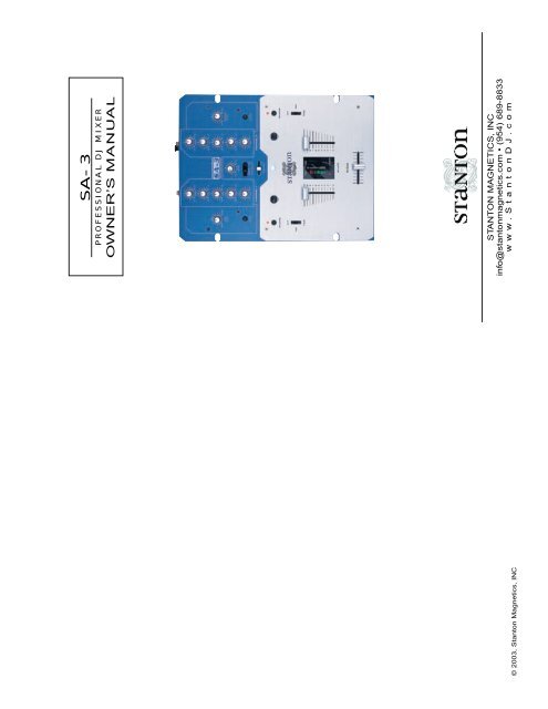
SA-3<br />
PROFESSION<strong>AL</strong> DJ MIXER<br />
OWNER’S <strong>MANU</strong><strong>AL</strong><br />
STANTON MAGNETICS, INC<br />
info@stantonmagnetics.com • (954) 689-8833<br />
www.<strong>Stanton</strong>DJ.com
SA3_manual_FIN<strong>AL</strong> 2/18/05 2:26 PM Page 2<br />
WELCOME! WARRANTY<br />
Thank you for making <strong>Stanton</strong> your first choice in professional DJ mixers.<br />
Our innovative family of mixers have been developed with input from the professional<br />
DJ community, <strong>Stanton</strong> offers a affordable combination of user-friendly<br />
mixers with functional design, rugged construction, and professional quality features<br />
which had been previously unavailable.<br />
This unit has been designed and manufactured using quality components.<br />
Therefore, it is warranted to be free from defects in materials (limited as specified<br />
below), and workmanship for a period of twelve (12) months from the original<br />
purchase date. During this period, all service and parts necessary to repair<br />
a defect will be free of charge. This limited warranty applies to mechanical parts<br />
which are subject to wear and tear as specified:<br />
<strong>Stanton</strong> and your authorized <strong>Stanton</strong> dealer are dedicated to your complete satisfaction<br />
by offering benchmark service and support throughout the long life of<br />
your <strong>Stanton</strong> product.<br />
• Faders specified durability: 15,000 cycles;<br />
• Rotary potentiometer, specified durability: 10,000 cycles;<br />
• Switches, specified durability: 10,000 cycles.<br />
We appreciate your patronage, and look forward to many years of making music<br />
together.<br />
Consequently, the parts listed above are warranted to be free from defects in<br />
materials and workmanship for a period of thirty days (30) days from the original<br />
purchase date.<br />
PLEASE READ CAREFULLY BEFORE USE<br />
For the warranty to be valid, please complete the warranty registration card<br />
attached or fill out the online registration at www.stantondj.com<br />
FAILURE TO FOLLOW THE INSTRUCTIONS PRINTED BELOW MAY VOID WARRANTY<br />
Mail completed warranty cards to:<br />
• Follow all security advice printed on your mixer<br />
<strong>Stanton</strong> Magnetics, Inc, 3000 SW 42st • Hollywood, FL 33312<br />
• When removing the unit's AC plug from the power source, grasp and pull<br />
the plug, NEVER the cord itself!<br />
• Avoid placing your mixer near heat sources, such as power amplifiers.<br />
• When in use, place your mixer on a stable surface, away from vibration.<br />
Always use care when carrying your mixer. Impact, or heavy vibration may<br />
compromise the unit's mechanical integrity. The manufacturer is not<br />
responsible for damage resulting from an impact, or misuse.<br />
• When in use, place your mixer away from sources of hum or noise, such as<br />
transformers, or electric motors.<br />
• To prevent overheating, always provide your mixer with adequate<br />
ventilation air space.<br />
• Avoid stepping on your mixer's AC cord. Repeated compression of the cord<br />
may lead to electrical shorting.<br />
• To avoid damage due to AC voltage peaks, always disconnect your mixer<br />
from the power source during electrical storms. If possible connect mixer to<br />
a surge protector.<br />
• Your mixer contains no user-serviceable parts. The manufacturer is not<br />
responsible for any damage or personal injury resulting from unauthorized<br />
user-servicing or modifications. In addition, the warranty will be void if any<br />
unauthorized service by the user is detected. Always return your mixer to<br />
an authorized <strong>Stanton</strong> dealer for servicing.
SA3_manual_FIN<strong>AL</strong> 2/18/05 2:26 PM Page 3<br />
TECHNIC<strong>AL</strong> SPECIFICATIONS<br />
Line inputs: 2 (RCA) x 2 channels, -10 dBV /10 kOhm<br />
Phono inputs: 2 (RCA) x 2 channels, -50 dBV / 47 kOhm<br />
Master output: 2 (TRS Balanced/RCA unbalanced),<br />
+4 dBu balanced / -10 dBV unbalanced<br />
Headphone output: 1 (1/4 inch), 1 (1/8 inch), greater than 32 Ohm load<br />
Frequency Response: 20 Hz - 20 kHz, +/- 1.5 dB<br />
Tone Control : Hi +9/-18 dB<br />
Mid +9/-25 dB<br />
Low +9/-25 dB<br />
S/N Ratio: Better than 94 dB (ref: max input level)<br />
Noise: -80 dBV (Line input to any output)<br />
T.H.D Less than 0.04% (1 kHz)<br />
Dimension(LxWxD): 12.4" x 9.25" x 4.33"in; (315 x 235 x 110mm)<br />
Weight: 6.6 lbs 3 kgs<br />
REPLACEMENT PARTS<br />
The following user replaceable parts are available from your local<br />
<strong>Stanton</strong> dealer.<br />
CFSA3 Crossfader<br />
LFSA3 Linefader<br />
CF-PG110 Penny & Giles crossfader<br />
CF-F1 Focus Fader V1<br />
CF-F2 Focus Fader V2<br />
PLSA3 Phono / Line switch<br />
3PLSA3 Phono / Line switch (w/Flash)<br />
PPSA3 PROTEKT panel<br />
PS-18US US Power Supply (110v)<br />
PS-18EU European Power Supply (220v)<br />
PS-18UK UK only Power Supply (240v)<br />
SA-3 FEATURES<br />
The SA-3 professional scratch<br />
mixer has been designed specifically<br />
for scratch DJs. The SA-3 is a<br />
clean, simple and easy to understand<br />
mixer design with the features<br />
that will help you as a scratch<br />
artist.<br />
• 2 channel scratch mixer.<br />
• Curve adjustment and reverse switch for Crossfader and Linefaders.<br />
• User replaceable / upgradeable faders.<br />
• Each channel features gain control, 3 band eq, and pan.<br />
• Headphone mute switch.<br />
• Dual headphone outputs (1/4"/6.3mm and 1/8"/3.5mm).<br />
• Balanced 1/4” and unbalanced RCA master outputs.<br />
• Master mute switch.<br />
• Rotatable 2 Position phono/line switch.<br />
• Mic channel with gain control.<br />
• Microphone mute switch.<br />
• Protekt Panel.<br />
• 2 line and 2 phono inputs.<br />
• Master / Cue switch.<br />
• Cue fader for cueing between programs.
SA3_manual_FIN<strong>AL</strong> 2/18/05 2:26 PM Page 4<br />
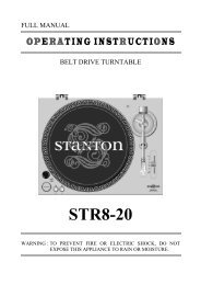
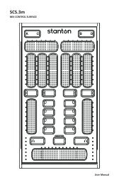
DESCRIPTION OF FUNCTIONS ROTATING THE TRANSFORM SWITCHES<br />
4<br />
5<br />
min max<br />
GAIN<br />
-26 +9<br />
HI<br />
4<br />
5<br />
min max<br />
GAIN<br />
-26 +9<br />
HI<br />
The input selector (transform) switches on the <strong>Stanton</strong> SA-3<br />
mixer can be rotated to 8 different positions. Follow the steps<br />
below to rotate the transform switch to the position you like.<br />
1. Make sure the mixer is powered off. Remove the faceplate of<br />
the mixer.<br />
1<br />
2<br />
3<br />
min max<br />
MIC<br />
LEVEL<br />
MUTE<br />
5<br />
5<br />
6<br />
-26 +9<br />
MID<br />
-26 +9<br />
LOW<br />
L R<br />
PAN<br />
7<br />
8<br />
www.stantondj.com<br />
SCRATCH ARTIST INSTRUMENT<br />
min max<br />
CUE<br />
LEVEL<br />
MASTER<br />
CUE<br />
CUE SELECT<br />
5<br />
5<br />
6<br />
-26 +9<br />
MID<br />
-26 +9<br />
LOW<br />
PAN<br />
R<br />
10<br />
11<br />
12<br />
min max<br />
MASTER<br />
LEVEL<br />
MUTE<br />
2. Remove the two outer screws<br />
from the transform switch as indicated<br />
in diagram. Do not remove<br />
the two inner screws. Removing<br />
the two inner screws will detach<br />
the switch from the plate.<br />
13<br />
14<br />
REVERSE<br />
9<br />
CHANNEL 1 CHANNEL 2<br />
16 17<br />
CH1<br />
CUE PAN<br />
CH2<br />
REVERSE<br />
3. Rotate the switch to the position<br />
you like. Replace the two<br />
outer screws to secure the switch<br />
in place.<br />
15<br />
MID<br />
CUT<br />
FADE FADE<br />
CUT<br />
MID<br />
Replacing the transform switch<br />
1. Follow steps 1 and 2 above.<br />
Remove switch from mixer and<br />
detach connector from switch.<br />
18<br />
20<br />
22<br />
19<br />
21<br />
REVERSE<br />
2. Attach connector for transform<br />
switch to replacement switch and replace two outer screws to<br />
secure the switch in place.<br />
REPLACING THE CROSSFADER<br />
TOP PANEL<br />
23<br />
1. Microphone level - Controls the attenuation level of the<br />
microphone input. Use the microphone level adjustment to find<br />
the right gain for your microphone, then use the microphone<br />
mute button (3) to mute the input when not in use.<br />
2. Microphone Mute LED - Indicates when microphone mute<br />
button (3) has been engaged.<br />
3. Microphone Mute - Mutes the microphone input.<br />
The SA-3 is compatible with the CFSA-3, Focus Faders V1/V2<br />
and with the Penny and Giles crossfaders. The SA-3 has two different<br />
circuits which need to be switched when changing<br />
between the faders. To switch the crossfader circuit, follow the<br />
instructions below:<br />
1. Follow steps 1 & 2 from the fader cleaning instructions.<br />
2. Remove the fader assembly and disconnect<br />
the cable coming from the mixer.<br />
3. The crossfader select switch is located<br />
inside the mixer, on the left side of the<br />
fader slot. In order to use the CFSA-3, FF1<br />
and Penny & Giles faders, make sure the<br />
switch is pressed DOWN. To use the CFF2,<br />
make sure the switch is in the UP position.<br />
L
SA3_manual_FIN<strong>AL</strong> 2/18/05 2:26 PM Page 5<br />
REMOVING FACEPLATE<br />
1. Unplug the power<br />
supply from the back<br />
of the mixer. Verify<br />
that the mixer is powered<br />
off.<br />
2. Remove the 4<br />
screws on the faceplate.<br />
Place the 4<br />
screws somewhere<br />
safe where they will<br />
not be lost.<br />
REVERSE<br />
CUT<br />
CHANNEL 1 CHANNEL 2<br />
CH1 CH2<br />
CUE PAN<br />
(BACKPANEL VIEW)<br />
2 2<br />
REVERSE<br />
CUT<br />
3. Remove the 3 fader<br />
knobs from the line<br />
faders and crossfader.<br />
MID<br />
FADE FADE<br />
3 3<br />
MID<br />
4. The faceplate can<br />
now be removed from<br />
the top of the mixer.<br />
HP MUTE<br />
3<br />
2<br />
2<br />
CLEANING FADERS<br />
1. Make sure the mixer<br />
is powered off. Remove<br />
the faceplate of the<br />
mixer by following the<br />
directions above.<br />
2. Remove the fader from the mixer<br />
by unscrewing the two outer screws<br />
on the fader plate. Do not remove<br />
the two inside screws on the fader<br />
plate, this will remove the fader from<br />
the fader plate.<br />
3. Once fader has been removed<br />
from mixer spray a small amount of<br />
contact cleaner into the fader and<br />
move the fader back and forth to<br />
disperse the cleaner.<br />
MIXER FUNCTIONS<br />
4. Input Gains - Controls the input sensitivity level for each<br />
channel. Use the input gain in conjunction with the LED meters<br />
(19) to properly set the levels of your input.<br />
5. Input Equalizers - Individual controls for high frequency,<br />
mid-range, and low frequency equalization with 9db of boost and<br />
25dB of kill. Note: Any changes made to EQ settings will change<br />
the overall output level of that input.<br />
6. Input Pan - Controls left / right output balance of each channel.<br />
7. Cue Level - Controls the output level of the headphone amp.<br />
8. Master / Cue Switch - Selects signal to be sent to headphone<br />
output. In “CUE” position, the cue pan fader (9) is used to<br />
select which input channel is to be monitored. In “MASTER”<br />
position the master output is sent directly to the headphones.<br />
9. Cue pan fader - Fades the headphone output from input 1 to<br />
input 2 when Master / Cue switch is in “Cue” mode.<br />
10. Master Level - Controls the overall output level of the master<br />
output.<br />
11. Master Mute Indicator - LED indicates when Master Mute<br />
switch (12) has been engaged.<br />
12. Master Mute - Mutes the master output of the mixer. Use the<br />
master mute in situations where you need to mute and unmute<br />
the mixer with out having to re-adjust your Master Level (10)<br />
control.<br />
13. Reverse Indicator - Bi-color (red & green) LED indicates<br />
when faders direction has been reversed (green = normal, red =<br />
reversed).<br />
14. Reverse Button - Reverses the direction of the fade on the<br />
corresponding fader.<br />
15. Line fader Curve Control - Selects taper of upfader curve<br />
between a fast cut, medium curve, and long fade.<br />
16. Input Select - Toggle switch selects the input source<br />
between the phono and line inputs located on the back of your<br />
mixer.
SA3_manual_FIN<strong>AL</strong> 2/18/05 2:26 PM Page 6<br />
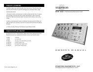
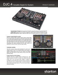
MIXER FUNCTIONS FRONT PANEL<br />
17. Power Indicator - Blue LED indicates when power has been<br />
switched on.<br />
18. Line Fader - The linefader controls the level of each channel<br />
to the master outputs.<br />
19. Level Meter - LED meter indicates level of each channel.<br />
The left LED meter is for channel 1. The right LED meter is for<br />
channel 2. Use the Input Gain (4) to adjust the signal to 0dB<br />
(yellow LED). The red LED on the meter indicates when the signal<br />
is close to clipping and distorting the output of the mixer.<br />
25. Crossfader Curve - Controls the taper (fade) shape of the<br />
crossfader (23). The crossfader curve control continually adjusts<br />
the curve from a sharp cut to a long fade.<br />
26. Headphone Outputs - 1/4” and 1/8” connector jacks for<br />
headphones.<br />
BACK PANEL<br />
20. Headphone Mute - Mutes the headphone output. This feature<br />
is very useful for quick cueing during mixing and scratching.<br />
21. Headphone Mute Indicator - Indicates when Headphone<br />
Mute (20) has been engaged.<br />
22. Crossfader Reverse Indicator - Indicates when crossfader<br />
reverse has been engaged.<br />
23. Crossfader - The crossfader fades between channel 1 and<br />
channel 2. The taper (curve) of the crossfader is determined by<br />
the crossfader curve control (23). The direction of the curve is<br />
determined by the crossfader reverse control (24).<br />
FRONT PANEL<br />
BACK PANEL<br />
Power - Power switch to turn the mixer “ON” or “OFF”<br />
AC IN: This is the input connection for the included power<br />
supply.<br />
Master - Connects to an amplifier, EQ, crossover, or other<br />
outboard signal processing. Connect balance connections<br />
to the TRS 1/4” connectors. Connect un-balanced connections<br />
to the RCA connectors.<br />
24<br />
25<br />
26<br />
Line - Line inputs are used to connect line level sources<br />
such as CD players, Mini Discs, DATs, samplers, ect.<br />
Ground - Connects to turntable ground cable to eliminate<br />
electrical hum. Ground cables are usually supplied with<br />
turntables.<br />
FRONT PANEL<br />
24. Crossfader Reverse - The crossfader reverse changes the<br />
direction of the fade on the crossfader (23).<br />
Phono - Connects to left and right RCA cables from<br />
turntable.<br />
Mic - 1/4” TRS connector for use with microphones.