SERVICE STATION MANUAL Vespa LX 125 - 150 4T Euro 3
Το επίσημο βιβλίο των εξουσιοδοτημένων συνεργείων της Piaggio.
Το επίσημο βιβλίο των εξουσιοδοτημένων συνεργείων της Piaggio.

You also want an ePaper? Increase the reach of your titles
YUMPU automatically turns print PDFs into web optimized ePapers that Google loves.
<strong>SERVICE</strong> <strong>STATION</strong> <strong>MANUAL</strong><br />
633976<br />
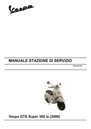
<strong>Vespa</strong> <strong>LX</strong> <strong>125</strong> - <strong>150</strong> <strong>4T</strong> <strong>Euro</strong> 3
<strong>SERVICE</strong> <strong>STATION</strong><br />
<strong>MANUAL</strong><br />
<strong>Vespa</strong> <strong>LX</strong> <strong>125</strong> - <strong>150</strong> <strong>4T</strong> <strong>Euro</strong> 3<br />
The descriptions and illustrations given in this publication are not binding. While the basic specifications<br />
as described and illustrated in this manual remain unchanged, PIAGGIO-GILERA reserves the right, at<br />
any time and without being required to update this publication beforehand, to make any changes to<br />
components, parts or accessories, which it considers necessary to improve the product or which are<br />
required for manufacturing or construction reasons.<br />
Not all versions shown in this publication are available in all Countries. The availability of single versions<br />
should be checked at the official Piaggio sales network.<br />
"© Copyright 2007 - PIAGGIO & C. S.p.A. Pontedera. All rights reserved. Reproduction of this publication<br />
in whole or in part is prohibited."<br />
PIAGGIO & C. S.p.A. - After-Sales<br />
V.le Rinaldo Piaggio, 23 - 56025 PONTEDERA (Pi)
<strong>SERVICE</strong> <strong>STATION</strong> <strong>MANUAL</strong><br />
<strong>Vespa</strong> <strong>LX</strong> <strong>125</strong> - <strong>150</strong> <strong>4T</strong> <strong>Euro</strong> 3<br />
This service station manual has been drawn up by Piaggio & C. Spa to be used by the workshops of<br />
Piaggio-Gilera dealers. It is assumed that the user of this manual for maintaining and repairing Piaggio<br />
vehicles has a basic knowledge of mechanical principles and vehicle repair technique procedures. Any<br />
significant changes to vehicle characteristics or to specific repair operations will be communicated by<br />
updates to this manual. Nevertheless, no mounting work can be satisfactory if the necessary equipment<br />
and tools are unavailable. It is therefore advisable to read the sections of this manual relating to special<br />
tools, along with the special tool catalogue.<br />
N.B. Provides key information to make the procedure easier to understand and carry out.<br />
CAUTION Refers to specific procedures to carry out for preventing damages to the vehicle.<br />
WARNING Refers to specific procedures to carry out to prevent injuries to the repairer.<br />
Personal safety Failure to completely observe these instructions will result in serious risk of personal<br />
injury.<br />
Safeguarding the environment Sections marked with this symbol indicate the correct use of the vehicle<br />
to prevent damaging the environment.<br />
Vehicle intactness The incomplete or non-observance of these regulations leads to the risk of serious<br />
damage to the vehicle and sometimes even the invalidity of the guarantee.
INDEX OF TOPICS<br />
CHARACTERISTICS<br />
CHAR<br />
TOOLING<br />
TOOL<br />
MAINTENANCE<br />
MAIN<br />
TROUBLESHOOTING<br />
TROUBL<br />
ELECTRICAL SYSTEM<br />
ELE SYS<br />
ENGINE FROM VEHICLE<br />
ENG VE<br />
ENGINE<br />
ENG<br />
SUSPENSIONS<br />
SUSP<br />
BRAKING SYSTEM<br />
BRAK SYS<br />
CHASSIS<br />
CHAS<br />
PRE-DELIVERY<br />
PRE DE<br />
TIME<br />
TIME
INDEX OF TOPICS<br />
CHARACTERISTICS<br />
CHAR
Characteristics <strong>Vespa</strong> <strong>LX</strong> <strong>125</strong> - <strong>150</strong> <strong>4T</strong> <strong>Euro</strong> 3<br />
Rules<br />
This section describes general safety rules for any maintenance operations performed on the vehicle.<br />
Safety rules<br />
- If work can only be done on the vehicle with the engine running, make sure that the premises are wellventilated,<br />
using special extractors if necessary; never let the engine run in an enclosed area. Exhaust<br />
fumes are toxic.<br />
- The battery electrolyte contains sulphuric acid. Protect your eyes, clothes and skin. Sulphuric acid is<br />
highly corrosive; in the event of contact with your eyes or skin, rinse thoroughly with abundant water<br />
and seek immediate medical attention.<br />
- The battery produces hydrogen, a gas that can be highly explosive. Do not smoke and avoid sparks<br />
or flames near the battery, especially when charging it.<br />
- Fuel is highly flammable and it can be explosive given some conditions. Do not smoke in the working<br />
area, and avoid open flames or sparks.<br />
- Clean the brake pads in a well-ventilated area, directing the jet of compressed air in such a way that<br />
you do not breathe in the dust produced by the wear of the friction material. Even though the latter<br />
contains no asbestos, inhaling dust is harmful.<br />
Maintenance rules<br />
- Use original PIAGGIO spare parts and lubricants recommended by the Manufacturer. Non-original or<br />
non-conforming spares may damage the vehicle.<br />
- Use only the appropriate tools designed for this vehicle.<br />
- Always use new gaskets, sealing rings and split pins upon refitting.<br />
- After removal, clean the components using non-flammable or low flash-point solvent. Lubricate all the<br />
work surfaces except the tapered couplings before refitting.<br />
- After refitting, make sure that all the components have been installed correctly and work properly.<br />
- For removal, overhaul and refit operations use only tools with metric measures. Metric bolts, nuts and<br />
screws are not interchangeable with coupling members with English measurement. Using unsuitable<br />
coupling members and tools may damage the scooter.<br />
- When carrying out maintenance operations on the vehicle that involve the electrical system, make<br />
sure the electric connections have been made properly, particularly the ground and battery connections.<br />
CHAR - 2
<strong>Vespa</strong> <strong>LX</strong> <strong>125</strong> - <strong>150</strong> <strong>4T</strong> <strong>Euro</strong> 3<br />
Characteristics<br />
Vehicle identification<br />
VEHICLE IDENTIFICATION<br />
Specification Desc./Quantity<br />
Chassis prefix (<strong>125</strong>) ZAPM44300 ÷ 1001<br />
Engine prefix (<strong>125</strong>) M444M ÷ 1001<br />
Chassis prefix (<strong>150</strong>) ZAPM44400 ÷ 1001<br />
Engine prefix (<strong>150</strong>) M445M ÷ 1001<br />
Dimensions and mass<br />
Specification<br />
Kerb weight<br />
WEIGHTS AND DIMENSIONS<br />
Desc./Quantity<br />
114 ± 5 kg<br />
CHAR - 3
Characteristics <strong>Vespa</strong> <strong>LX</strong> <strong>125</strong> - <strong>150</strong> <strong>4T</strong> <strong>Euro</strong> 3<br />
Specification<br />
Maximum height<br />
Width<br />
Wheelbase<br />
Length<br />
Desc./Quantity<br />
1140 mm<br />
740 mm<br />
1280 mm<br />
1800 mm<br />
Engine<br />
ENGINE<br />
Specification<br />
Desc./Quantity<br />
Engine<br />
Single-cylinder, 4-stroke Piaggio LEADER<br />
Timing system<br />
Single overhead camshaft (SOHC) with 2 valves<br />
Valve clearance intake 0.10<br />
outlet 0.15<br />
Bore x stroke (<strong>125</strong>)<br />
57 x 48.6 mm<br />
Bore/stroke (<strong>150</strong>)<br />
62.6 x 48.6 mm<br />
Cubic capacity (<strong>125</strong>)<br />
124 cm³<br />
Cubic capacity (<strong>150</strong>)<br />
151 cm³<br />
Compression ratio (<strong>125</strong>/<strong>150</strong>) 10.6 ± 0.5 ÷ 1<br />
Engine idle speed<br />
1,650±100 rpm<br />
Carburettor<br />
KEIHIN CVEK26<br />
Start-up<br />
Electrical / Kick starter<br />
Max power (<strong>125</strong>)<br />
7.65 kW at 8250 rpm<br />
Max power (<strong>150</strong>)<br />
8.9 kW at 7750 rpm<br />
Max torque (<strong>125</strong>)<br />
9.6 Nm at 7250 rpm<br />
Max torque (<strong>150</strong>)<br />
11.8 Nm at 6500 rpm<br />
Cooling<br />
Forced air circulation.<br />
Transmission<br />
Specification<br />
Transmission<br />
TRANSMISSION<br />
Desc./Quantity<br />
With automatic expandable pulley variator with torque<br />
server, V belt, automatic clutch, gear reduction<br />
unit and transmission housing with forced air<br />
circulation cooling.<br />
Capacities<br />
Specification<br />
Engine oil<br />
Rear hub oil<br />
Fuel tank capacity<br />
CAPACITY<br />
Desc./Quantity<br />
61 in³ (1,000 cm³)<br />
~ 100 cm³<br />
~ 8.5 litres (2 l of which is reserve)<br />
CHAR - 4
<strong>Vespa</strong> <strong>LX</strong> <strong>125</strong> - <strong>150</strong> <strong>4T</strong> <strong>Euro</strong> 3<br />
Characteristics<br />
Electrical system<br />
Specification<br />
Start-up<br />
Spark plug<br />
ELECTRICAL SYSTEM<br />
Desc./Quantity<br />
Electrical / Kick starter<br />
Champion RG6YC- NGK CR7EB<br />
Frame and suspensions<br />
Brakes<br />
Specification<br />
Chassis<br />
Steering and suspensions<br />
FRAME AND SUSPENSIONS<br />
Desc./Quantity<br />
Unitised body made of stamped plate.<br />
Steering tube articulated on the front wheel carrier<br />
hub; helicoidal spring suspension and double-acting<br />
hydraulic shock absorber; rear with doubleacting<br />
shock absorber and coaxial spring adjustable<br />
to 4 positions at preloading.<br />
Specification<br />
Front brake<br />
Rear brake<br />
BRAKES<br />
Desc./Quantity<br />
Disc brake (Ø 200 mm) with hydraulic control (lever<br />
on the far right of the handlebar) and fixed<br />
calliper.<br />
Ø110 mm drum brake<br />
Wheels and tyres<br />
WHEELS AND TYRES<br />
Specification<br />
Desc./Quantity<br />
Front wheel rim Die-cast aluminium alloy; 2.50 x11"<br />
Front tyre Tubeless; 110/70-11"<br />
Rear wheel rim Die-cast aluminium alloy; 3.00 x 10"<br />
Rear tyre Tubeless; 120/70-10"<br />
Front tyre pressure<br />
1.6 bar<br />
Rear tyre pressure<br />
2 bar<br />
Rear wheel pressure (rider and passenger):<br />
2.3 bar<br />
Secondary air<br />
In order to reduce polluting emissions, the vehicle<br />
is furnished with a catalytic converter in the muffler.<br />
To favour the catalytic process, an extra amount<br />
of oxygen is added to the exhaust through a secondary<br />
air system (SAS).<br />
CHAR - 5
Characteristics <strong>Vespa</strong> <strong>LX</strong> <strong>125</strong> - <strong>150</strong> <strong>4T</strong> <strong>Euro</strong> 3<br />
This system allows more oxygen to be added to<br />
the unburned gases before they reach the converter,<br />
thus improving the action of the catalytic<br />
converter.<br />
The air enters the exhaust duct from the head, and<br />
is purified by a black filter.<br />
The system is fitted with a control valve that disables<br />
operation while decelerating to avoid unwanted<br />
noise.<br />
To ensure the best functioning of the SAS system<br />
clean the filter as indicated in the scheduled maintenance<br />
table.<br />
The filter sponge should be cleaned with water and<br />
mild soap, then it should be dried with a cloth and<br />
slight blows of compressed air.<br />
Carburettor<br />
<strong>125</strong>cc Version<br />
Kehin<br />
CARBURETTOR SETTING<br />
Specification<br />
Desc./Quantity<br />
Type<br />
CVEK26<br />
Throttle valve diameter Ø 26.5<br />
Diffuser diameter Ø 26.4<br />
Setting stamping<br />
270C<br />
Maximum jet 82<br />
Maximum air jet (on the body) 85<br />
Tapered pin stamping<br />
NJHA<br />
Throttle valve spring<br />
130 ÷ 180 gr.<br />
Minimum jet 42<br />
Idle air jet (on the body) <strong>150</strong><br />
Idle mixture adjustment screw initial opening<br />
2 ½<br />
Starter jet 35<br />
Starter air jet (on the body) Ø 1.5<br />
Starter pin travel 10 mm (at 24°)<br />
Starter resistance 20 Ohm (at 24°)<br />
<strong>150</strong>cc Version<br />
CHAR - 6
<strong>Vespa</strong> <strong>LX</strong> <strong>125</strong> - <strong>150</strong> <strong>4T</strong> <strong>Euro</strong> 3<br />
Characteristics<br />
Kehin<br />
CARBURETTOR SETTING<br />
Specification<br />
Desc./Quantity<br />
Type<br />
CVEK26<br />
Throttle valve diameter Ø 26.5<br />
Diffuser diameter Ø 26.4<br />
Setting stamping<br />
271B<br />
Maximum jet 80<br />
Maximum air jet (on the body) MAJ 85<br />
Maximum air jet (on the body) MAJ2 80<br />
Tapered pin stamping<br />
NELA<br />
Throttle valve spring<br />
130 ÷ 180 gr.<br />
Minimum jet 35<br />
Idle air jet (on the body) <strong>150</strong><br />
Idle mixture adjustment screw initial opening<br />
1 ¾<br />
Starter jet 42<br />
Starter air jet (on the body) Ø 1.5<br />
Starter pin travel 10 mm (at 24°)<br />
Starter resistance 20 Ohm (at 24°)<br />
Tightening Torques<br />
LUBRICATION<br />
Name<br />
Torque in Nm<br />
Hub oil drainage cap 15 ÷ 17<br />
Oil filter 4 ÷ 6<br />
Oil pump cover screws 5 - 6<br />
Oil pump screws 5 - 6<br />
Pump control pulley screw 10 ÷ 14<br />
Chain cover screws 4 ÷ 6<br />
Oil sump screws 10 ÷ 14<br />
Minimum oil pressure sensor 12 ÷ 14<br />
Blow-by recovery duct fixing screws 3 - 4<br />
HEAD AND CYLINDER<br />
Name<br />
Torque in Nm<br />
Ignition spark plug 12 ÷ 14<br />
Head cover screws 11 ÷ 13<br />
Nuts fixing head to cylinder (*) 28 ÷ 30<br />
Head fixing screws (external) 11 ÷ 13<br />
Starter ground screw 7 ÷ 8.5<br />
Flywheel cover screw 1 ÷ 2<br />
Flywheel air manifold screw 3 ÷ 4<br />
Pressure reducer counterweight retainer 7 ÷ 8.5<br />
Camshaft pulley screw 12 ÷ 14<br />
Timing chain tensioner slider screw 10 ÷ 14<br />
Starter ground support screw 11 ÷ 15<br />
Tensioner screws 11 ÷ 13<br />
Timing chain tensioner central screw 5 - 6<br />
Camshaft retention plate screw 5 - 6<br />
Nut fixing muffler to cylinder head 16 ÷ 18<br />
CHAR - 7
Characteristics <strong>Vespa</strong> <strong>LX</strong> <strong>125</strong> - <strong>150</strong> <strong>4T</strong> <strong>Euro</strong> 3<br />
Name<br />
Torque in Nm<br />
Head intake manifold screw 11 ÷ 13<br />
TRANSMISSION<br />
Name<br />
Torque in Nm<br />
Drive pulley nut 75 ÷ 83<br />
Transmission cover screw 11 ÷ 13<br />
Driven pulley shaft nut 54 ÷ 60<br />
Rear hub cap screw 24 ÷ 27<br />
Clutch unit nut on driven pulley 45 ÷ 50<br />
FLYWHEEL<br />
Name<br />
Torque in Nm<br />
Flywheel fan screws 3 ÷ 4<br />
Stator assembly screws (°) 3 ÷ 4<br />
Flywheel nut 52 ÷ 58<br />
Pick-up screw 3 ÷ 4<br />
(°) Apply LOCTITE 243 threadlock<br />
CRANKCASE AND CRANKSHAFT<br />
Name<br />
Torque in Nm<br />
Internal engine crankcase bulkhead (transmission-side<br />
4 ÷ 6<br />
half shaft) screws<br />
Oil filter on crankcase fitting 27 ÷ 33<br />
Rear brake cam tightening screw 11 ÷ 13<br />
Engine-crankcase coupling screws 11 ÷ 13<br />
Pre-filter cap 24 ÷ 30<br />
Starter motor fixing screw 11 ÷ 13<br />
Muffler to crankcase fixing screws 24 ÷ 27<br />
Engine oil drainage cap 24 ÷ 30<br />
STEERING ASSEMBLY<br />
Name<br />
Torque in Nm<br />
Steering upper ring nut 35 ÷ 40<br />
Lower steering ring nut 12 - 14<br />
Handlebar fixing screw 50 ÷ 55<br />
FRAME ASSEMBLY<br />
Name<br />
Torque in Nm<br />
Swinging arm pin - frame 44 ÷ 52<br />
Engine-swinging arm bolt 33 ÷ 41<br />
Stand bolt 32 ÷ 40<br />
Swinging arm silent-block containment bolt 33 ÷ 41<br />
FRONT SUSPENSION<br />
Name<br />
Torque in Nm<br />
Shock absorber upper nut 20 ÷ 30<br />
Front wheel axle nut 75 ÷ 90<br />
Shock absorber upper bracket bolts 20 ÷ 25<br />
Wheel rim screws 20 ÷ 25<br />
Shock absorber lower bolts (°) 20 ÷ 27<br />
CHAR - 8
<strong>Vespa</strong> <strong>LX</strong> <strong>125</strong> - <strong>150</strong> <strong>4T</strong> <strong>Euro</strong> 3<br />
Characteristics<br />
FRONT BRAKE<br />
Name<br />
Torque in Nm<br />
Brake fluid pump-hose fitting 8 ÷ 12<br />
Brake fluid pipe-calliper fitting 20 ÷ 25<br />
Screw tightening calliper to the support 20 ÷ 25<br />
Brake disc screw 5 ÷ 6.5<br />
Oil bleed valve (on the calliper) 10 ÷ 12<br />
Handlebar pump 7 ÷ 10<br />
Overhaul data<br />
REAR SUSPENSION<br />
Name<br />
Torque in Nm<br />
Rear wheel axle 104 ÷ 126<br />
Shock absorber lower clamp 33 ÷ 41<br />
Shock absorber/frame nut: 20 ÷ 25<br />
Assembly clearances<br />
Cylinder - piston assy.<br />
Version <strong>150</strong><br />
COUPLING BETWEEN (AXIS-WERKE) PISTON AND (<strong>150</strong>) CYLINDER<br />
Name Initials Cylinder Piston Play on fitting<br />
Coupling A 62.580 ÷ 62.587 62.533 ÷ 62.540 0.040 ÷ 0.054<br />
Coupling B 62.587 ÷ 62.594 62.540 ÷ 62.547 0.040 ÷ 0.054<br />
Coupling C 62.594 ÷ 62.601 62.547 ÷ 62.554 0.040 ÷ 0.054<br />
Coupling D 62.601 ÷ 62.608 62.554 ÷ 62.561 0.040 ÷ 0.054<br />
Coupling 1st oversize<br />
A1 62.780 ÷ 62.787 62.733 ÷ 62.740 0.040 ÷ 0.054<br />
coupling 1st oversize<br />
B1 62.787 ÷ 62.794 62.740 ÷ 62.747 0.040 ÷ 0.054<br />
Coupling 1st oversize<br />
C1 62.794 ÷ 62.801 62.747 ÷ 62.754 0.040 ÷ 0.054<br />
Coupling 1st oversize<br />
D1 62.801 ÷ 62.808 62.754 ÷ 62.761 0.040 ÷ 0.054<br />
Coupling 2nd oversize<br />
A2 62.980 ÷ 62.987 62.933 ÷ 62.940 0.040 ÷ 0.054<br />
Coupling 2nd oversize<br />
B2 62.987 ÷ 62.994 62.940 ÷ 62.947 0.040 ÷ 0.054<br />
Coupling 2nd oversize<br />
C2 62.994 ÷ 63.001 62.947 ÷ 62.954 0.040 ÷ 0.054<br />
Coupling 2nd oversize<br />
D2 63.001 ÷ 63.008 62.954 ÷ 62.961 0.040 ÷ 0.054<br />
Coupling 3rd oversize<br />
A3 63.180 ÷ 63.187 63.133 ÷ 63.140 0.040 ÷ 0.054<br />
Coupling 3rd oversize<br />
B3 63.187 ÷ 63.194 63.140 ÷ 63.147 0.040 ÷ 0.054<br />
CHAR - 9
Characteristics <strong>Vespa</strong> <strong>LX</strong> <strong>125</strong> - <strong>150</strong> <strong>4T</strong> <strong>Euro</strong> 3<br />
Name Initials Cylinder Piston Play on fitting<br />
Coupling 3rd oversize<br />
C3 63.194 ÷ 63.201 63.147 ÷ 63.154 0.040 ÷ 0.054<br />
Coupling 3rd oversize<br />
D3 63.201 ÷ 63.208 63.154 ÷ 63.161 0.040 ÷ 0.054<br />
COUPLING BETWEEN (RIGHT WAY) PISTON AND (<strong>150</strong>) CYLINDER<br />
Name Initials Cylinder Piston Play on fitting<br />
Coupling A 62.580 ÷ 62.587 62.541 ÷ 62.548 0.032 ÷ 0.046<br />
Coupling B 62.587 ÷ 62.594 62.548 ÷ 62.555 0.032 ÷ 0.046<br />
Coupling C 62.594 ÷ 62.601 62.555 ÷ 62.562 0.032 ÷ 0.046<br />
Coupling D 62.601 ÷ 62.608 62.562 ÷ 62.569 0.032 ÷ 0.046<br />
Version <strong>125</strong><br />
COUPLING BETWEEN PISTON AND ALUMINIUM CYLINDER WITH CAST IRON LINER<br />
(<strong>125</strong>)<br />
Name Initials Cylinder Piston Play on fitting<br />
Coupling A 56.980 ÷ 56.987 56.933 ÷ 56.940 0.040 - 0.054<br />
Coupling B 56.987 ÷ 56.994 56.940 ÷ 56.947 0.040 - 0.054<br />
Coupling C 56.994 ÷ 57.001 56.947 ÷ 56.954 0.040 - 0.054<br />
Coupling D 57.001 ÷ 57.008 56.954 ÷ 56.961 0.040 - 0.054<br />
Coupling 1st increase<br />
A1 57.180 ÷ 57.187 57.133 ÷ 57.140 0.040 - 0.054<br />
Coupling 1st increase<br />
B1 57.187 ÷ 57.194 57.140 ÷ 57.147 0.040 - 0.054<br />
Coupling 1st increase<br />
C1 57.194 ÷ 57.201 57.147 ÷ 57.154 0.040 - 0.054<br />
Coupling 1st increase<br />
D1 57.201 ÷ 57.208 57.154 ÷ 57.161 0.040 - 0.054<br />
Coupling 2nd increase<br />
A2 57.380 ÷ 57.387 57.333 ÷ 57.340 0.040 - 0.054<br />
Coupling 2nd increase<br />
B2 57.387 ÷ 57.394 57.340 ÷ 57.347 0.040 - 0.054<br />
Coupling 2nd increase<br />
C2 57.394 ÷ 57.401 57.347 ÷ 57.354 0.040 - 0.054<br />
Coupling 2nd increase<br />
D2 57.401 ÷ 57.408 57.354 ÷ 57.361 0.040 - 0.054<br />
Coupling 3rd oversize<br />
A3 57.580 ÷ 57.587 57.533 ÷ 57.540 0.040 - 0.054<br />
Coupling 3rd oversize<br />
B3 57.587 ÷ 57.594 57.540 ÷ 57.547 0.040 - 0.054<br />
Coupling 3rd oversize<br />
C3 57.594 ÷ 57.601 57.547 ÷ 57.554 0.040 - 0.054<br />
Coupling 3rd oversize<br />
D3 57.601 ÷ 57.608 57.554 ÷ 57.561 0.040 - 0.054<br />
PISTON TO CAST IRON CYLINDER COUPLING (<strong>125</strong>)<br />
Name Initials Cylinder Piston Play on fitting<br />
Coupling M 56.997 ÷ 57.004 56.944 ÷ 56.951 0.046 ÷ 0.060<br />
Coupling N 57.004 ÷ 57.011 56.951 ÷ 56.958 0.046 ÷ 0.060<br />
Coupling O 57.011 ÷ 57.018 56.958 ÷ 56.965 0.046 ÷ 0.060<br />
Coupling P 57.018 ÷ 57.025 56.965 ÷ 56.972 0.046 ÷ 0.060<br />
CHAR - 10
<strong>Vespa</strong> <strong>LX</strong> <strong>125</strong> - <strong>150</strong> <strong>4T</strong> <strong>Euro</strong> 3<br />
Characteristics<br />
Name Initials Cylinder Piston Play on fitting<br />
Coupling 1st oversize<br />
M1 57.197 ÷ 57.204 57.144 ÷ 57.151 0.046 ÷ 0.060<br />
Coupling 1st oversize<br />
N1 57.204 ÷ 57.211 57.151 ÷ 57.158 0.046 ÷ 0.060<br />
Coupling 1st oversize<br />
O1 57.211 ÷ 57.218 57.158 ÷ 57.165 0.046 ÷ 0.060<br />
Coupling 1st oversize<br />
P1 57.218 ÷ 57.225 57.165 ÷ 57.172 0.046 ÷ 0.060<br />
Coupling 2nd oversize<br />
M2 57.397 ÷ 57.404 57.344 ÷ 57.351 0.046 ÷ 0.060<br />
Coupling 2nd oversize<br />
N2 57.404 ÷ 57.411 57.351 ÷ 57.358 0.046 ÷ 0.060<br />
Coupling 2nd oversize<br />
O2 57.411 ÷ 57.418 57.358 ÷ 57.365 0.046 ÷ 0.060<br />
Coupling 2nd oversize<br />
P2 57.418 ÷ 57.425 57.365 ÷ 57.372 0.046 ÷ 0.060<br />
Coupling 3rd oversize<br />
M3 57.597 ÷ 57.604 57.544 ÷ 57.551 0.046 ÷ 0.060<br />
Coupling 3rd oversize<br />
N3 57.604 ÷ 57.611 57.551 ÷ 57.558 0.046 ÷ 0.060<br />
Coupling 3rd oversize<br />
O3 57.611 ÷ 57.618 57.558 ÷ 57.565 0.046 ÷ 0.060<br />
Coupling 3rd oversize<br />
P3 57.618 ÷ 57.625 57.565 ÷ 57.572 0.046 ÷ 0.060<br />
Piston rings<br />
SEALING RINGS (<strong>125</strong>)<br />
Name Description Dimensions Initials Quantity<br />
Compression ring 57 x 1 A 0.15 ÷ 0.30<br />
Oil scraper ring 57x1 A 0.10 ÷ 0.30<br />
Oil scraper ring 57x2.5 A 0.10 ÷ 0.35<br />
Compression ring<br />
57.2 x 1 A 0.15 ÷ 0.30<br />
1st oversize<br />
Oil scraper ring 1st<br />
57.2x1 A 0.10 ÷ 0.30<br />
oversize<br />
Oil scraper ring 1st<br />
57.2x2.5 A 0.10 ÷ 0.35<br />
oversize<br />
Compression ring<br />
57.4x1 A 0.15 ÷ 0.30<br />
2nd oversize<br />
Oil scraper ring<br />
57.4x1 A 0.10 ÷ 0.30<br />
2nd oversize<br />
Oil scraper ring<br />
57.4x2.5 A 0.10 ÷ 0.35<br />
2nd oversize<br />
Compression ring<br />
57.6x1 A 0.15 ÷ 0.30<br />
3rd oversize<br />
Oil scraper ring 3rd<br />
57.6x1 A 0.10 ÷ 0.30<br />
oversize<br />
Oil scraper ring 3rd<br />
oversize<br />
57.6x2.5 A 0.10 ÷ 0.35<br />
Maximum clearance after use: 1 mm<br />
CHAR - 11
Characteristics <strong>Vespa</strong> <strong>LX</strong> <strong>125</strong> - <strong>150</strong> <strong>4T</strong> <strong>Euro</strong> 3<br />
SEALING RINGS (<strong>150</strong>)<br />
Name Description Dimensions Initials Quantity<br />
Compression ring 62.6x1 A 0.15 ÷ 0.30<br />
Oil scraper ring 62.6x1 A 0.20 ÷ 0.40<br />
Oil scraper ring 62.6x2.5 A 0.20 ÷ 0.40<br />
Compression ring<br />
62.8x1 A 0.15 ÷ 0.30<br />
1st oversize<br />
Oil scraper ring 1st<br />
62.8x1 A 0.20 ÷ 0.40<br />
oversize<br />
Oil scraper ring 1st<br />
62.8x2.5 A 0.20 ÷ 0.40<br />
oversize<br />
Compression ring<br />
63.0 x 1 A 0.15 ÷ 0.30<br />
2nd oversize<br />
Oil scraper ring<br />
63.0 x 1 A 0.20 ÷ 0.40<br />
2nd oversize<br />
Oil scraper ring<br />
63.0 x 2.5 A 0.20 ÷ 0.40<br />
2nd oversize<br />
Compression ring<br />
63.2 x 1 A 0.15 ÷ 0.30<br />
3rd oversize<br />
Oil scraper ring 3rd<br />
63.2 x 1 A 0.20 ÷ 0.40<br />
oversize<br />
Oil scraper ring 3rd<br />
oversize<br />
63.2 x 2.5 A 0.20 ÷ 0.40<br />
Crankcase - crankshaft - connecting rod<br />
AXIAL CLEARANCE BETWEEN CRANKSHAFT AND CONNECTING ROD<br />
Name Description Dimensions Initials Quantity<br />
Half-shaft, transmission<br />
16.6 +0-0.05 A D = 0.20 - 0.50<br />
side<br />
Flywheel-side halfshaft<br />
16.6 +0-0.05 B D = 0.20 - 0.50<br />
Connecting rod<br />
18 -0.10 -0.15 C 0.20 ÷ 0.50<br />
with PP<br />
Crank pin width 51.400 E<br />
AXIAL CLEARANCE BETWEEN CRANKSHAFT AND CRANKSHAFT HALF-BEARINGS<br />
Name Description Dimensions Initials Quantity<br />
Crankshaft Category 1 28.998 ÷ 29.004<br />
Crankshaft Category 2 29.004 ÷ 29.010<br />
CHAR - 12
<strong>Vespa</strong> <strong>LX</strong> <strong>125</strong> - <strong>150</strong> <strong>4T</strong> <strong>Euro</strong> 3<br />
Characteristics<br />
Name Description Dimensions Initials Quantity<br />
Crankcase Class 1 32.953 ÷ 32.959<br />
Crankcase Class 2 32.959 ÷ 32.965<br />
Crankshaft halfbearing<br />
Category B - blue 1.973 ÷ 1.976<br />
Crankshaft halfbearinlow<br />
Category C - yel-<br />
1.976 ÷ 1.979<br />
Crankshaft halfbearing<br />
Type E - green 1.979 ÷ 1.982<br />
Crankshaft class 1<br />
E - E<br />
- Crankcase class<br />
1<br />
Crankshaft class 1<br />
C - C<br />
- Crankcase class<br />
2<br />
Crankshaft class 2<br />
C - C<br />
- Crankcase class<br />
1<br />
Crankshaft class 2<br />
- Crankcase class<br />
2<br />
B - B<br />
Crankshaft/crankcase axial clearance: 0.15 ÷ 0.40<br />
Slot packing system<br />
- Provisionally fit the piston into the cylinder, without any base gasket.<br />
- Assemble a dial gauge on the specific tool<br />
- Set the dial gauge to zero at a contrast plane with an average precharge, for example 5 mm. Keeping<br />
the zero setting position, fit the tool on the cylinder and lock it with 2 nuts, as shown in the figure.<br />
- Rotate the crankshaft until TDC (the inverted point of the dial gauge rotation)<br />
CHAR - 13
Characteristics <strong>Vespa</strong> <strong>LX</strong> <strong>125</strong> - <strong>150</strong> <strong>4T</strong> <strong>Euro</strong> 3<br />
- Calculate the difference between the two measurements: use the chart below to identify the thickness<br />
of the cylinder base gasket to be used for refitting. Correctly identify the cylinder base gasket thickness<br />
to keep the correct compression ratio.<br />
- Remove the special tool and the cylinder.<br />
Characteristic<br />
Compression ratio (<strong>125</strong>/<strong>150</strong>)<br />
10.6 ± 0.5 ÷ 1<br />
SHIMMING SYSTEM (<strong>125</strong>)<br />
Specification<br />
Desc./Quantity<br />
Value measured 0 ÷ 0.1<br />
Thickness 0.8 ± 0.05<br />
Value measured 0.1 ÷ 0.3<br />
Thickness 0.6 ± 0.05<br />
Value measured 0.3 - 0.4<br />
Thickness 0.4 ± 0.05<br />
SHIMMING SYSTEM (<strong>150</strong>)<br />
Specification<br />
Desc./Quantity<br />
Value measured 1 ÷ 1.1<br />
Thickness 0.8 ± 0.05<br />
Value measured 1.1 ÷ 1.3<br />
Thickness 0.6 ± 0.05<br />
Value measured 1.3 ÷ 1.4<br />
Thickness 0.4 ± 0.05<br />
Products<br />
RECOMMENDED PRODUCTS TABLE<br />
Product Description Specifications<br />
AGIP ROTRA 80W-90 Rear hub oil SAE 80W/90 Oil that exceeds the<br />
requirements of API GL3 specifications<br />
AGIP BRAKE 4 Brake fluid FMVSS DOT4 Synthetic fluid<br />
AGIP CITY HI TEC <strong>4T</strong> Oil to lubricate flexible transmissions<br />
(brakes, throttle control<br />
and odometer)<br />
Oil for 4-stroke engines<br />
CHAR - 14
<strong>Vespa</strong> <strong>LX</strong> <strong>125</strong> - <strong>150</strong> <strong>4T</strong> <strong>Euro</strong> 3<br />
Characteristics<br />
Product Description Specifications<br />
AGIP FILTER OIL Oil for air filter sponge Mineral oil with specific additives<br />
for increased adhesiveness<br />
AGIP CITY HI TEC <strong>4T</strong> Engine oil SAE 5W-40, API SL, ACEA A3,<br />
JASO MA Synthetic oil<br />
AGIP GREASE MU3<br />
AGIP GP 330<br />
Grease for odometer transmission<br />
gear case<br />
Grease for brake control levers,<br />
throttle, stand<br />
Soap-based lithium grease with<br />
NLGI 3; ISO-L-XBCHA3, DIN<br />
K3K-20<br />
White calcium complex soapbased<br />
spray grease with NLGI 2;<br />
ISO-L-XBCIB2<br />
CHAR - 15
Characteristics <strong>Vespa</strong> <strong>LX</strong> <strong>125</strong> - <strong>150</strong> <strong>4T</strong> <strong>Euro</strong> 3<br />
CHAR - 16
INDEX OF TOPICS<br />
TOOLING<br />
TOOL
Tooling <strong>Vespa</strong> <strong>LX</strong> <strong>125</strong> - <strong>150</strong> <strong>4T</strong> <strong>Euro</strong> 3<br />
Stores code<br />
001330Y<br />
APPROPRIATE TOOL<br />
Description<br />
Tool for fitting steering seats<br />
001467Y009<br />
Driver for OD 42 mm bearings<br />
001467Y013<br />
Pliers to extract ø 15-mm bearings<br />
002465Y<br />
Pliers for circlips<br />
005095Y<br />
Engine support<br />
008564Y<br />
Flywheel extractor<br />
TOOL - 2
<strong>Vespa</strong> <strong>LX</strong> <strong>125</strong> - <strong>150</strong> <strong>4T</strong> <strong>Euro</strong> 3<br />
Tooling<br />
Stores code<br />
020004Y<br />
Description<br />
Punch for removing fifth wheels<br />
from headstock<br />
020055Y<br />
Wrench for steering tube ring nut<br />
020074Y<br />
Support base for checking crankshaft<br />
alignment<br />
020<strong>150</strong>Y<br />
Air heater support<br />
020151Y<br />
Air heater<br />
020193Y<br />
Oil pressure gauge<br />
TOOL - 3
Tooling <strong>Vespa</strong> <strong>LX</strong> <strong>125</strong> - <strong>150</strong> <strong>4T</strong> <strong>Euro</strong> 3<br />
Stores code<br />
020262Y<br />
Description<br />
Crankcase splitting strip<br />
020263Y<br />
Sheath for driven pulley fitting<br />
020287Y<br />
Clamp to assemble piston on cylinder<br />
020306Y<br />
Punch for assembling valve seal<br />
rings<br />
020329Y<br />
MityVac vacuum-operated pump<br />
020330Y<br />
Stroboscopic light for timing control<br />
TOOL - 4
<strong>Vespa</strong> <strong>LX</strong> <strong>125</strong> - <strong>150</strong> <strong>4T</strong> <strong>Euro</strong> 3<br />
Tooling<br />
Stores code<br />
020331Y<br />
Description<br />
Digital multimeter<br />
020332Y<br />
Digital rev counter<br />
020333Y<br />
Single battery charger<br />
020334Y<br />
Multiple battery charger<br />
TOOL - 5
Tooling <strong>Vespa</strong> <strong>LX</strong> <strong>125</strong> - <strong>150</strong> <strong>4T</strong> <strong>Euro</strong> 3<br />
Stores code<br />
020335Y<br />
Description<br />
Magnetic support for dial gauge<br />
020357Y<br />
020359Y<br />
32 x 35 mm adaptor<br />
42x47-mm adaptor<br />
020360Y<br />
Adaptor 52 x 55 mm<br />
020363Y<br />
20 mm guide<br />
020364Y<br />
25-mm guide<br />
TOOL - 6
<strong>Vespa</strong> <strong>LX</strong> <strong>125</strong> - <strong>150</strong> <strong>4T</strong> <strong>Euro</strong> 3<br />
Tooling<br />
Stores code<br />
020368Y<br />
Description<br />
driving pulley lock wrench<br />
020375Y<br />
Adaptor 28 x 30 mm<br />
020376Y<br />
Adaptor handle<br />
020382Y011<br />
adapter for valve removal tool<br />
020409Y<br />
Multimeter adaptor - Peak voltage<br />
detection<br />
TOOL - 7
Tooling <strong>Vespa</strong> <strong>LX</strong> <strong>125</strong> - <strong>150</strong> <strong>4T</strong> <strong>Euro</strong> 3<br />
Stores code<br />
020412Y<br />
Description<br />
15 mm guide<br />
020414Y<br />
28-mm guide<br />
020423Y<br />
driven pulley lock wrench<br />
020424Y<br />
Driven pulley roller casing fitting<br />
punch<br />
020425Y<br />
Punch for flywheel-side oil seal<br />
020426Y<br />
Piston fitting fork<br />
TOOL - 8
<strong>Vespa</strong> <strong>LX</strong> <strong>125</strong> - <strong>150</strong> <strong>4T</strong> <strong>Euro</strong> 3<br />
Tooling<br />
Stores code<br />
020427Y<br />
Description<br />
Piston fitting band<br />
020428Y<br />
Piston position check support<br />
020430Y<br />
Pin lock fitting tool<br />
020431Y<br />
Valve oil seal extractor<br />
020434Y<br />
Oil pressure control fitting<br />
020444Y<br />
Tool for fitting/ removing the driven<br />
pulley clutch<br />
TOOL - 9
Tooling <strong>Vespa</strong> <strong>LX</strong> <strong>125</strong> - <strong>150</strong> <strong>4T</strong> <strong>Euro</strong> 3<br />
Stores code<br />
020565Y<br />
Description<br />
Flywheel lock calliper spanner<br />
020622Y<br />
Transmission-side oil guard<br />
punch<br />
020481Y005<br />
EFI Technology interface wiring<br />
020460Y<br />
Scooter diagnosis and tester<br />
020469Y<br />
Reprogramming kit for scooter<br />
diagnosis tester<br />
TOOL - 10
<strong>Vespa</strong> <strong>LX</strong> <strong>125</strong> - <strong>150</strong> <strong>4T</strong> <strong>Euro</strong> 3<br />
Tooling<br />
Stores code<br />
020641Y<br />
Description<br />
EFI Technology software upgrade<br />
TOOL - 11
Tooling <strong>Vespa</strong> <strong>LX</strong> <strong>125</strong> - <strong>150</strong> <strong>4T</strong> <strong>Euro</strong> 3<br />
TOOL - 12
INDEX OF TOPICS<br />
MAINTENANCE<br />
MAIN
Maintenance <strong>Vespa</strong> <strong>LX</strong> <strong>125</strong> - <strong>150</strong> <strong>4T</strong> <strong>Euro</strong> 3<br />
Maintenance chart<br />
Brake fluid - change<br />
Engine oil - level check/ top-up<br />
EVERY 2 YEARS<br />
Action<br />
EVERY 3000 KM<br />
Action<br />
80'<br />
Engine oil - replacement<br />
Hub oil - change<br />
Oil filter (net filter) - clean<br />
Idle speed (*) - adjustment<br />
Throttle lever - adjustment<br />
Steering - adjustment<br />
Brake control levers - greasing<br />
Brake pads - check condition and wear<br />
Brake fluid level - check<br />
Safety locks - check<br />
Electrical system and battery - check<br />
Tyre pressure and wear - check<br />
Vehicle and brake test - road test<br />
(*) See instructions in «Idle speed adjustment» section<br />
<strong>150</strong>'<br />
Engine oil - replacement<br />
Hub oil level - check<br />
Spark plug electrode gap - check<br />
Air filter - clean<br />
Engine oil - change<br />
Oil filter (net filter) - clean<br />
Valve clearance - adjustment<br />
Variable speed rollers/pads - check<br />
Driving belt - check<br />
Brake pads - check condition and wear<br />
Brake fluid level - check<br />
Electrical system and battery - check<br />
Centre stand - lubrication<br />
Tyre pressure and wear - check<br />
Vehicle and brake test - road test<br />
AFTER 1000 KM<br />
Action<br />
AFTER 6000 KM, 18000 KM, 54000 KM<br />
Action<br />
160'<br />
Engine oil - replacement<br />
AFTER 12000 KM, 60000 KM<br />
Action<br />
MAIN - 2
<strong>Vespa</strong> <strong>LX</strong> <strong>125</strong> - <strong>150</strong> <strong>4T</strong> <strong>Euro</strong> 3<br />
Maintenance<br />
Hub oil level - check<br />
Air filter - clean<br />
Engine oil - change<br />
Oil filter (net filter) - clean<br />
Spark plug - replacement<br />
Idle speed (*) - adjustment<br />
Throttle lever - adjustment<br />
Pads and variator rollers - replacement<br />
Driving belt - replacement<br />
Odometer cable - greasing<br />
Steering - adjustment<br />
Brake control levers - greasing<br />
Brake pads - check condition and wear<br />
Brake fluid level - check<br />
Transmission elements - lubrication<br />
Safety locks - check<br />
Suspensions - check<br />
Electrical system and battery - check<br />
Headlight - adjustment<br />
Centre stand - lubrication<br />
Secondary air filter - cleaning<br />
Tyre pressure and wear - check<br />
Vehicle and brake test - road test<br />
(*) See instructions in «Idle speed adjustment» section<br />
Action<br />
175'<br />
Engine oil - replacement<br />
Hub oil - change<br />
Air filter - clean<br />
Engine oil - change<br />
Oil filter (net filter) - clean<br />
Spark plug - replacement<br />
Idle speed (*) - adjustment<br />
Throttle lever - adjustment<br />
Pads and variator rollers - replacement<br />
Driving belt - replacement<br />
Cylinder ventilation system - cleaning<br />
Odometer cable - greasing<br />
Steering - adjustment<br />
Brake control levers - greasing<br />
Brake pads - check condition and wear<br />
Brake fluid level - check<br />
Transmission elements - lubrication<br />
Safety locks - check<br />
Suspensions - check<br />
Electrical system and battery - check<br />
Headlight - adjustment<br />
Tyre pressure and wear - check<br />
Secondary air filter - cleaning<br />
Centre stand - lubrication<br />
Vehicle and brake test - road test<br />
AFTER 24000 KM, 48000 KM<br />
Action<br />
MAIN - 3
Maintenance <strong>Vespa</strong> <strong>LX</strong> <strong>125</strong> - <strong>150</strong> <strong>4T</strong> <strong>Euro</strong> 3<br />
(*) See instructions in «Idle speed adjustment» section<br />
95'<br />
Engine oil - replacement<br />
Hub oil level - check<br />
Spark plug electrode gap - check<br />
Air filter - clean<br />
Engine oil - change<br />
Oil filter (net filter) - clean<br />
Slide pads and variator rollers - check<br />
Driving belt - check<br />
Brake pads - check condition and wear<br />
Brake fluid level - check<br />
Electrical system and battery - check<br />
Centre stand - lubrication<br />
Tyre pressure and wear - check<br />
Vehicle and brake test - road test<br />
270'<br />
Engine oil - replacement<br />
Hub oil - change<br />
Spark plug - replacement<br />
Air filter - clean<br />
Engine oil - change<br />
Oil filter (net filter) - clean<br />
Valve clearance - adjustment<br />
Idle speed (*) - adjustment<br />
Throttle lever - adjustment<br />
Pads and variator rollers - replacement<br />
Driving belt - replacement<br />
Odometer cable - greasing<br />
Steering - adjustment<br />
Brake control levers - greasing<br />
Brake pads - check condition and wear<br />
Brake fluid level - check<br />
Flexible brake tubes - replacement<br />
Transmission elements - lubrication<br />
Safety locks - check<br />
Suspensions - check<br />
Electrical system and battery - check<br />
Headlight - adjustment<br />
Secondary air filter - cleaning<br />
Centre stand - lubrication<br />
Tyre pressure and wear - check<br />
Vehicle and brake test - road test<br />
(*) See instructions in «Idle speed adjustment» section<br />
AFTER 30000 KM, 42000 KM, 66000 KM<br />
Action<br />
AFTER 36000 KM<br />
Action<br />
270'<br />
AFTER 72,000 KM<br />
MAIN - 4
<strong>Vespa</strong> <strong>LX</strong> <strong>125</strong> - <strong>150</strong> <strong>4T</strong> <strong>Euro</strong> 3<br />
Maintenance<br />
Engine oil - replacement<br />
Hub oil - change<br />
Spark plug - replacement<br />
Air filter - clean<br />
Engine oil - change<br />
Oil filter (net filter) - clean<br />
Valve clearance - adjustment<br />
Idle speed (*) - adjustment<br />
Throttle lever - adjustment<br />
Pads and variator rollers - replacement<br />
Driving belt - replacement<br />
Odometer cable - greasing<br />
Steering - adjustment<br />
Cylinder ventilation system - check<br />
Brake control levers - greasing<br />
Brake pads - check condition and wear<br />
Brake fluid level - check<br />
Flexible brake tubes - replacement<br />
Transmission elements - lubrication<br />
Safety locks - check<br />
Suspensions - check<br />
Electrical system and battery - check<br />
Headlight - adjustment<br />
Secondary air filter - cleaning<br />
Centre stand - lubrication<br />
Tyre pressure and wear - check<br />
Vehicle and brake test - road test<br />
(*) See instructions in «Idle speed adjustment» section<br />
Action<br />
Checking the spark advance<br />
The scooter is fitted with a control unit that manages ignition advance according to engine revs and the<br />
opening angle of the carburettor throttle valve.<br />
Spark advance variation<br />
Braking system<br />
LIMITER ACTIVATION<br />
Specification<br />
Desc./Quantity<br />
Operation threshold First threshold : 9500 ± 50<br />
Second threshold : 9800 ± 50<br />
Reactivation threshold First threshold : 9500 ± 50<br />
Second threshold : 9350 ± 50<br />
Spark elimination First threshold : 15 on 15<br />
Second threshold : 15 on 15<br />
MAIN - 5
Maintenance <strong>Vespa</strong> <strong>LX</strong> <strong>125</strong> - <strong>150</strong> <strong>4T</strong> <strong>Euro</strong> 3<br />
Level check<br />
Proceed as follows:<br />
- Rest the vehicle on its centre stand with the handlebars<br />
perfectly horizontal;<br />
- Check the level of liquid with the related warning<br />
light «A».<br />
A certain lowering of the level is caused by wear<br />
on the pads.<br />
Top-up<br />
Proceed as follows:<br />
- Remove the tank cap by loosening the two<br />
screws, remove the gasket and top up using only<br />
the liquid specified without exceeding the maximum<br />
level.<br />
CAUTION<br />
ONLY USE DOT 4-CLASSIFIED BRAKE FLUID.<br />
CAUTION<br />
MAKE SURE THE BRAKE FLUID DOES NOT<br />
GET INTO YOUR EYES OR ON YOUR SKIN OR<br />
CLOTHES. IF THIS HAPPENS ACCIDENTALLY,<br />
WASH WITH WATER.<br />
CAUTION<br />
BRAKE CIRCUIT FLUID IS VERY CORROSIVE;<br />
MAKE SURE THAT IT DOES NOT COME INTO<br />
CONTACT WITH THE PAINTWORK.<br />
CAUTION<br />
THE BRAKE FLUID IS HYGROSCOPIC, THAT<br />
IS, IT ABSORBS MOISTURE FROM THE SUR-<br />
ROUNDING AIR. IF THE CONTENT OF MOIS-<br />
TURE IN THE BRAKING FLUID EXCEEDS A<br />
CERTAIN VALUE, BRAKING WILL BE INEFFI-<br />
CIENT.<br />
NEVER USE BRAKE LIQUID IN OPEN OR PAR-<br />
TIALLY USED CONTAINERS.<br />
UNDER NORMAL CLIMATIC CONDITIONS, RE-<br />
PLACE FLUID AS INDICATED IN THE SCHED-<br />
ULED MAINTENANCE TABLE.<br />
N.B.<br />
SEE THE BRAKING SYSTEM CHAPTER WITH<br />
REGARD TO THE CHANGING OF BRAKE FLU-<br />
ID AND THE BLEEDING OF AIR FROM THE<br />
CIRCUITS.<br />
Recommended products<br />
AGIP BRAKE 4 Brake fluid<br />
MAIN - 6
<strong>Vespa</strong> <strong>LX</strong> <strong>125</strong> - <strong>150</strong> <strong>4T</strong> <strong>Euro</strong> 3<br />
Maintenance<br />
FMVSS DOT4 Synthetic fluid<br />
Headlight adjustment<br />
Proceed as follows:<br />
1. Place the vehicle in running order and with the<br />
tyres inflated to the prescribed pressure, on a flat<br />
surface 10 m away from a white screen situated in<br />
a shaded area, making sure that the longitudinal<br />
axis of the scooter is perpendicular to the screen;<br />
2. Turn on the headlight and check that the borderline<br />
of the projected light beam on the screen<br />
is not lower than 9/10 of the distance from the<br />
ground to the centre of vehicle headlamp and higher<br />
than 7/10;<br />
3. If otherwise, adjust the right headlight with screw<br />
«A».<br />
N.B.<br />
THE ABOVE PROCEDURE COMPLIES WITH<br />
THE EUROPEAN STANDARDS REGARDING<br />
MAXIMUM AND MINIMUM HEIGHT OF LIGHT<br />
BEAMS. REFER TO THE STATUTORY REGU-<br />
LATIONS IN FORCE IN EVERY COUNTRY<br />
WHERE THE vehicle IS USED.<br />
SAS filters inspection and cleaning<br />
Proceed as follows:<br />
- Remove the right-hand side fairing<br />
- Remove the screw on the rear part, to the right<br />
of the footrest, indicated in the photograph<br />
- Remove the spoiler terminal<br />
MAIN - 7
Maintenance <strong>Vespa</strong> <strong>LX</strong> <strong>125</strong> - <strong>150</strong> <strong>4T</strong> <strong>Euro</strong> 3<br />
- Remove the screw fixing the SAS valve to the<br />
flywheel cover, indicated in the photograph.<br />
- Remove the 6 flywheel cover screws indicated in<br />
the photograph and remove the flywheel cover.<br />
- Remove the filter indicated in the photograph<br />
- Check that the gasket is in good conditions<br />
- Check the SAS filter housing for dents or deformations<br />
- Clean the SAS filter carefully. Replace the filter if<br />
it is damaged or deformed.<br />
To refit, carry out the removal operations but in reverse<br />
order.<br />
CAUTION<br />
WHEN TRAVELLING ON DUSTY ROADS, THE<br />
AIR FILTER MUST BE CLEANED MORE OFTEN<br />
THAN SHOWN IN THE SCHEDULED MAINTE-<br />
NANCE CHART.<br />
CAUTION<br />
NEVER RUN THE ENGINE WITHOUT THE SEC-<br />
ONDARY AIR FILTER<br />
MAIN - 8
INDEX OF TOPICS<br />
TROUBLESHOOTING<br />
TROUBL
Troubleshooting <strong>Vespa</strong> <strong>LX</strong> <strong>125</strong> - <strong>150</strong> <strong>4T</strong> <strong>Euro</strong> 3<br />
Engine<br />
Poor performance<br />
POOR PERFORMANCE<br />
Possible Cause<br />
Operation<br />
Air filter blocked or dirty.<br />
Remove the sponge, wash with water and car<br />
shampoo, then soak it in a mixture of 50% petrol<br />
and 50% specific oil. Press with your hand without<br />
squeezing, allow it to drip dry and refit.<br />
Fuel nozzles or cock clogged or dirty Dismantle, wash with solvent and dry with compressed<br />
air<br />
Dirty or faulty vacuum-operated cock Check the filter on the cock, remove the petrol and<br />
wash the tank, if necessary. Replace the cock as<br />
a last resource.<br />
Failing automatic starter on the carburettor Check the electrical wiring and mechanical movement,<br />
replace if necessary.<br />
Excessive driving belt wear<br />
Check it and replace, if necessary<br />
Lack of compression parts, cylinder and valves<br />
Replace the worn parts<br />
wear<br />
Oil level exceeds maximum<br />
Check for causes and fill to reach the correct level<br />
Excess of encrustations in the combustion chamber<br />
valves<br />
Descale the cylinder, the piston, the head and the<br />
Incorrect timing or worn timing system elements Time the system again or replace the worn parts<br />
Muffler obstructed<br />
Replace<br />
Inefficient automatic transmission Check the rollers and the pulley movement, replace<br />
the damaged parts and lubricate the movable<br />
guide of the driven pulley with grease.<br />
Wrong valve adjustment<br />
Adjust the valve clearance properly<br />
Overheated valves<br />
Remove the head and the valves, grind or replace<br />
the valves<br />
Valve seat distorted<br />
Replace the head assembly<br />
Worn cylinder, Worn or broken piston rings Replace the piston cylinder assembly or just the<br />
piston rings<br />
Rear wheel spins at idle<br />
Starting difficulties<br />
REAR WHEEL ROTATES WITH ENGINE AT IDLE<br />
Possible Cause<br />
Operation<br />
Idling rpm too high<br />
Adjust the engine idle speed.<br />
Clutch fault<br />
Check the springs / clutch masses<br />
Possible Cause<br />
Battery flat<br />
DIFFICULTY STARTING UP<br />
Operation<br />
Check the state of the battery. If it shows signs of<br />
sulphation replace it and bring the new battery into<br />
TROUBL - 2
<strong>Vespa</strong> <strong>LX</strong> <strong>125</strong> - <strong>150</strong> <strong>4T</strong> <strong>Euro</strong> 3<br />
Troubleshooting<br />
Possible Cause<br />
Operation<br />
service charging it for eight hours at a current of<br />
1/10 of the capacity of the battery itself<br />
Faulty spark plug or incorrect ignition advance Replace the spark plug or check the ignition circuit<br />
components<br />
- Engine flooded. Try starting-up with the throttle fully open. If the<br />
engine fails to start, remove the spark plug, dry it<br />
and before refitting, make the motor turn so as to<br />
expel the fuel excess taking care to connect the<br />
cap to the spark plug, and this in turn to the ground.<br />
If the fuel tank is empty, refuel and start up.<br />
Incorrect valve sealing or valve adjustment Inspect the head and/or restore the correct clearance<br />
Rpm too low at start-up or engine and start-up Check the starter motor and the kick-starter unit<br />
system damaged<br />
Altered fuel characteristics<br />
Drain off the fuel no longer up to standard; then,<br />
refill<br />
Vacuum operated cock failure Check that fuel is adequately supplied through the<br />
pipe by applying a vacuum to the suction pipe<br />
Failing automatic starter on the carburettor Check the electrical wiring and mechanical movement,<br />
replace if necessary.<br />
Start-up enabling buttons failure Check continuity using an Ohm meter, with the<br />
switch pressed; replace if necessary<br />
Carburettor nozzles clogged or dirty Dismantle, wash with solvent and dry with compressed<br />
air<br />
Air filter obstructed or dirty.<br />
Remove the sponge, wash with water and car<br />
shampoo, then soak it in a mixture of 50% petrol<br />
and 50% specific oil. Press with your hand without<br />
squeezing, allow it to drip dry and refit.<br />
Fuel pump fault<br />
Check the pump control device<br />
Excessive oil consumption/Exhaust smoke<br />
EXCESSIVE OIL CONSUMPTION/SMOKEY EXHAUST<br />
Possible Cause<br />
Worn valve guides<br />
Worn valve oil guard<br />
Oil leaks from the couplings or from the gaskets<br />
Worn or broken piston rings or piston rings that<br />
have not been fitted properly<br />
Insufficient lubrication pressure<br />
Operation<br />
Check and replace the head unit if required<br />
Replace the valve oil guard<br />
Check and replace the gaskets or restore the coupling<br />
seal<br />
Replace the piston cylinder unit or just the piston<br />
rings<br />
Possible Cause<br />
By-Pass remains open<br />
Oil pump with excessive clearance<br />
Oil filter too dirty<br />
Oil level too low<br />
POOR LUBRICATION PRESSURE<br />
Operation<br />
Check the By-Pass and replace if required. Carefully<br />
clean the By-Pass area.<br />
Perform the dimensional checks on the oil pump<br />
components<br />
Replace the cartridge filter<br />
Restore the level adding the recommended oil<br />
type<br />
TROUBL - 3
Troubleshooting <strong>Vespa</strong> <strong>LX</strong> <strong>125</strong> - <strong>150</strong> <strong>4T</strong> <strong>Euro</strong> 3<br />
Engine tends to cut-off at full throttle<br />
THE MOTOR TENDS TO STOP AT MAXIMUM THROTTLE<br />
Possible Cause<br />
Maximum jet clogged<br />
Water or condensate in the carburettor tank<br />
Level in tank too low<br />
Engine tends to cut-off at idle<br />
Operation<br />
Remove the carburettor, wash with solvent and dry<br />
with compressed air<br />
Remove the tank, wash with solvent and dry with<br />
compressed air<br />
Restore the level in the tank by bending on the float<br />
the thrusting reed of the petrol inlet rod so as to<br />
have the float parallel to the tank level with the<br />
carburettor inverted.<br />
THE ENGINE TENDS TO STOP AT IDLE SPEED<br />
Possible Cause<br />
Incorrect idle adjustment<br />
Incorrect timing<br />
The starter remains on<br />
Faulty spark plug or incorrect ignition advance<br />
Pressure too low at the end of compression<br />
Minimum nozzle dirty<br />
High fuel consumption<br />
Operation<br />
Adjust using the rpm indicator<br />
Time the system and check the timing system<br />
components<br />
Check: electric wiring, circuit not interrupted, mechanical<br />
movement and power supply; replace if<br />
necessary<br />
Replace the spark plug or check the ignition circuit<br />
components<br />
Check the thermal group seals and replace worn<br />
components<br />
Wash the nozzle with solvent and dry with compressed<br />
air<br />
Possible Cause<br />
Air filter blocked or dirty.<br />
Inefficient Starter<br />
Loose nozzles<br />
Incorrect float level<br />
Transmission and brakes<br />
EXCESSIVE FUEL CONSUMPTION<br />
Operation<br />
Clean according to the procedure<br />
Check: electric wiring, circuit continuity, mechanical<br />
sliding and power supply<br />
Check the maximum and minimum nozzles are<br />
adequately fixed in their fittings<br />
Restore the level in the tank by bending on the float<br />
the thrusting reed of the petrol inlet rod so as to<br />
have the float parallel to the tank level with the<br />
carburettor inverted.<br />
TROUBL - 4
<strong>Vespa</strong> <strong>LX</strong> <strong>125</strong> - <strong>150</strong> <strong>4T</strong> <strong>Euro</strong> 3<br />
Troubleshooting<br />
Clutch grabbing or performing inadequately<br />
IRREGULAR CLUTCH PERFORMANCE OR SLIPPAGE<br />
Possible Cause<br />
Slippage or irregular functioning<br />
Insufficient braking<br />
Operation<br />
Check that there is no grease on the masses.<br />
Check that the faying surface between the clutch<br />
masses and the clutch bell is mainly in the middle<br />
and with equivalent specifications on the three<br />
masses.<br />
Check that the clutch bell is not scored or worn<br />
abnormally<br />
Never run the engine without the clutch bell<br />
Possible Cause<br />
Worn brake pads or shoes<br />
Front brake disk loose or deformed<br />
Air bubbles inside the hydraulic braking system<br />
Fluid leakage in hydraulic braking system<br />
INEFFICIENT OR NOISY BRAKING<br />
Operation<br />
Replace the brake pads or shoes and check for<br />
brake disk or drum wear conditions.<br />
Check the brake disc screws are locked; use a dial<br />
gauge and a wheel mounted on the vehicle to<br />
measure the axial shift of the disc.<br />
Carefully bleed the hydraulic braking system,<br />
(there must be no flexible movement of the brake<br />
lever).<br />
Failing elastic fittings, plunger or brake pump<br />
seals, replace<br />
Excessive backlash in the rear brake control cable Adjust the backlash with the appropriate adjuster<br />
located on the back part of the crankcase.<br />
Brakes overheating<br />
Possible Cause<br />
Rubber gaskets swollen or stuck<br />
Compensation holes on the pump clogged<br />
Brake disc slack or distorted<br />
Electrical system<br />
Defective piston sliding<br />
BRAKES OVERHEATING<br />
Operation<br />
Replace gaskets.<br />
Clean carefully and blast with compressed air<br />
Check the brake disc screws are locked; use a dial<br />
gauge and a wheel mounted on the vehicle to<br />
measure the axial shift of the disc.<br />
Check calliper and replace any damaged part.<br />
Battery<br />
Possible Cause<br />
Battery<br />
BATTERY<br />
Operation<br />
The battery is the electrical device in the system<br />
that requires the most frequent inspections and<br />
TROUBL - 5
Troubleshooting <strong>Vespa</strong> <strong>LX</strong> <strong>125</strong> - <strong>150</strong> <strong>4T</strong> <strong>Euro</strong> 3<br />
Possible Cause<br />
Operation<br />
thorough maintenance. If the vehicle is not used<br />
for some time (1 month or more) the battery needs<br />
to be recharged periodically. The battery runs<br />
down completely in the course of 5 ÷ 6 months. If<br />
the battery is fitted on a motorcycle, be careful not<br />
to invert the connections, keeping in mind that the<br />
black ground wire is connected to the negative terminal<br />
while the red wire is connected to the terminal<br />
marked+. Follow the instructions in the ELEC-<br />
TRICAL SYSTEM chapter for the recharging of the<br />
batteries.<br />
Turn signal lights malfunction<br />
Possible Cause<br />
Electronic ignition device failure<br />
Steering and suspensions<br />
TURN INDICATOR NOT WORKING<br />
Operation<br />
With the key switch set to "ON" jump the contacts<br />
1 (Blue-Black) and 5 (Orange) on the control unit<br />
connector.<br />
If by operating the turn indicator control the lights<br />
are not steadily on, replace the control unit; otherwise,<br />
check the cable harness and the switch.<br />
Heavy steering<br />
Possible Cause<br />
Steering hardening<br />
STEERING HARDENING<br />
Operation<br />
Check the tightening of the top and bottom ring<br />
nuts. If irregularities continue in turning the steering<br />
even after making the above adjustments,<br />
check the seats in which the ball bearings rotate:<br />
if they are recessed or if the balls are squashed,<br />
replace them.<br />
Excessive steering play<br />
Possible Cause<br />
Excessive steering backlash<br />
EXCESSIVE STEERING CLEARANCE<br />
Operation<br />
Check the tightening of the top ring nut. If irregularities<br />
continue in turning the steering even after<br />
making the above adjustments, check the seats in<br />
which the ball bearings rotate: replace if they are<br />
recessed.<br />
TROUBL - 6
<strong>Vespa</strong> <strong>LX</strong> <strong>125</strong> - <strong>150</strong> <strong>4T</strong> <strong>Euro</strong> 3<br />
Troubleshooting<br />
Noisy suspension<br />
Possible Cause<br />
Noisy suspension<br />
NOISY SUSPENSION<br />
Operation<br />
If the front suspension is noisy, check: that the<br />
front shock absorber works properly and the ball<br />
bearings are good condition. Finally, check the<br />
locking torque of the wheel axle nut, the brake calliper<br />
and the disc. Check that the swinging arm<br />
connecting the engine to the chassis and the rear<br />
shock absorber work properly.<br />
Suspension oil leakage<br />
OIL LEAKAGE FROM SUSPENSION<br />
Possible Cause<br />
Operation<br />
Oil leakage from suspension<br />
Replace the damper.<br />
TROUBL - 7
Troubleshooting <strong>Vespa</strong> <strong>LX</strong> <strong>125</strong> - <strong>150</strong> <strong>4T</strong> <strong>Euro</strong> 3<br />
TROUBL - 8
INDEX OF TOPICS<br />
ELECTRICAL SYSTEM<br />
ELE SYS
Electrical system <strong>Vespa</strong> <strong>LX</strong> <strong>125</strong> - <strong>150</strong> <strong>4T</strong> <strong>Euro</strong> 3<br />
KEY (With electric pump)<br />
1. Electronic ignition device<br />
2. Immobilizer aerial<br />
3.TPS potentiometer<br />
4. Magneto flywheel - Pick-up<br />
5. Diagnostics socket<br />
6. Ma J2 air valve (<strong>150</strong>)<br />
7. Voltage regulator<br />
8. Main fuses<br />
9. Battery<br />
10. Starter motor<br />
11. Start up remote control switch<br />
12. Secondary fuses<br />
13. Start-up button<br />
14. Stop button on rear brake<br />
15. Stop button on front brake<br />
16. Horn button<br />
17. Horn<br />
18. Light switch<br />
19. Turn signal switch<br />
ELE SYS - 2
<strong>Vespa</strong> <strong>LX</strong> <strong>125</strong> - <strong>150</strong> <strong>4T</strong> <strong>Euro</strong> 3<br />
Electrical system<br />
20. License plate light bulb<br />
21. Rear left turn indicator<br />
22. Rear light assembly<br />
23. Rear right turn indicator<br />
24. Front left turn indicator<br />
25. Headlight<br />
A. Twin-filament bulb<br />
B. Front position light bulb<br />
26. Front right turn indicator<br />
27. Remote control headlight<br />
28. Key switch<br />
29. Fuel level transmitter<br />
30. Engine oil pressure sensor<br />
31. Odometer with warning lights and fuel gauge<br />
A. Low fuel warning light<br />
B. Right turn indicator warning light<br />
C. Left turn indicator warning light<br />
D. Instrument panel lighting bulbs<br />
E. Headlight warning light<br />
F. Oil pressure warning light<br />
G. High-beam warning light<br />
H. Immobiliser/diagnosis LED<br />
32. Turn indicators sound alarm wiring<br />
33. Fuel pump<br />
34.Electric pump control device<br />
35. Spark plug<br />
36. HV coil<br />
37. Carburettor heater<br />
38. Automatic starter<br />
39. External temperature sensor<br />
ELE SYS - 3
Electrical system <strong>Vespa</strong> <strong>LX</strong> <strong>125</strong> - <strong>150</strong> <strong>4T</strong> <strong>Euro</strong> 3<br />
KEY (Without electric pump)<br />
1. Electronic ignition device<br />
2. Immobilizer aerial<br />
3.TPS potentiometer<br />
4. Magneto flywheel - Pick-up<br />
5. Diagnostics socket<br />
6. Ma J2 air valve (<strong>150</strong>)<br />
7. Voltage regulator<br />
8. Main fuses<br />
9. Battery<br />
10. Starter motor<br />
11. Start up remote control switch<br />
12. Secondary fuses<br />
13. Start-up button<br />
14. Stop button on rear brake<br />
15. Stop button on front brake<br />
16. Horn button<br />
17. Horn<br />
18. Light switch<br />
19. Turn signal switch<br />
ELE SYS - 4
<strong>Vespa</strong> <strong>LX</strong> <strong>125</strong> - <strong>150</strong> <strong>4T</strong> <strong>Euro</strong> 3<br />
Electrical system<br />
20. License plate light bulb<br />
21. Rear left turn indicator<br />
22. Rear light assembly<br />
23. Rear right turn indicator<br />
24. Front left turn indicator<br />
25. Headlight<br />
A. Twin-filament bulb<br />
B. Front position light bulb<br />
26. Front right turn indicator<br />
27. Remote control headlight<br />
28. Key switch<br />
29. Fuel level transmitter<br />
30. Engine oil pressure sensor<br />
31. Odometer with warning lights and fuel gauge<br />
A. Low fuel warning light<br />
B. Right turn indicator warning light<br />
C. Left turn indicator warning light<br />
D. Instrument panel lighting bulbs<br />
E. Headlight warning light<br />
F. Oil pressure warning light<br />
G. High-beam warning light<br />
H. Immobiliser/diagnosis LED<br />
32. Turn indicators sound alarm wiring<br />
33. Fuel pump<br />
34. Spark plug<br />
35. HV coil<br />
36. Carburettor heater<br />
37. Automatic starter<br />
38. External temperature sensor<br />
KEY<br />
Ar: Orange Az: Sky Blue Bi: White Bl: Blue Gi: Yellow Gr: Grey Ma: Brown Ne: Black Ro: Pink Rs:<br />
Red Ve: Green Vi: Purple<br />
Conceptual diagrams<br />
ELE SYS - 5
Electrical system <strong>Vespa</strong> <strong>LX</strong> <strong>125</strong> - <strong>150</strong> <strong>4T</strong> <strong>Euro</strong> 3<br />
Ignition<br />
LEGENDA (Con pompa elettrica)<br />
1. Dispositivo di accensione elettronica<br />
2. Antenna immobilizer<br />
8. Fusibili principali<br />
9. Batteria<br />
28. Commutatore a chiave<br />
35. Candela<br />
36. Bobina A.T.<br />
ELE SYS - 6
<strong>Vespa</strong> <strong>LX</strong> <strong>125</strong> - <strong>150</strong> <strong>4T</strong> <strong>Euro</strong> 3<br />
Electrical system<br />
LEGENDA (Senza pompa elettrica)<br />
1. Dispositivo di accensione elettronica<br />
2. Antenna immobilizer<br />
8. Fusibili principali<br />
9. Batteria<br />
28. Commutatore a chiave<br />
34. Candela<br />
35. Bobina A.T.<br />
ELE SYS - 7
Electrical system <strong>Vespa</strong> <strong>LX</strong> <strong>125</strong> - <strong>150</strong> <strong>4T</strong> <strong>Euro</strong> 3<br />
Headlights and automatic starter section<br />
LEGENDA (Con pompa elettrica)<br />
1. Dispositivo di accensione elettronica<br />
8. Fusibili principali<br />
9. Batteria<br />
12. Fusibili secondari<br />
18. Deviatore luci<br />
20. Lampada illuminazione targa<br />
22. Fanale posteriore completo<br />
25. Proiettore<br />
A. Lampada biluce<br />
B. Lampada luce di posizione anteriore<br />
27. Teleruttore proiettore<br />
28. Commutatore a chiave<br />
31. Contakm. con spie e strumento indicatore di livello<br />
A. Spia riserva carburante<br />
B. Spia lampeggiatore destro<br />
C. Spia lampeggiatore sinistro<br />
D. Lampade illuminazione strumento<br />
ELE SYS - 8
<strong>Vespa</strong> <strong>LX</strong> <strong>125</strong> - <strong>150</strong> <strong>4T</strong> <strong>Euro</strong> 3<br />
Electrical system<br />
E. Spia luci<br />
F. Spia pressione olio<br />
G. Spia luci abbaglianti<br />
H. Led dissuasione e diagnostica<br />
37. Riscaldatore carburatore<br />
38. Starter automatico<br />
LEGENDA (Senza pompa elettrica)<br />
1. Dispositivo di accensione elettronica<br />
8. Fusibili principali<br />
9. Batteria<br />
12. Fusibili secondari<br />
18. Deviatore luci<br />
20. Lampada illuminazione targa<br />
22. Fanale posteriore completo<br />
25. Proiettore<br />
A. Lampada biluce<br />
B. Lampada luce di posizione anteriore<br />
27. Teleruttore proiettore<br />
28. Commutatore a chiave<br />
31. Contakm. con spie e strumento indicatore di livello<br />
ELE SYS - 9
Electrical system <strong>Vespa</strong> <strong>LX</strong> <strong>125</strong> - <strong>150</strong> <strong>4T</strong> <strong>Euro</strong> 3<br />
A. Spia riserva carburante<br />
B. Spia lampeggiatore destro<br />
C. Spia lampeggiatore sinistro<br />
D. Lampade illuminazione strumento<br />
E. Spia luci<br />
F. Spia pressione olio<br />
G. Spia luci abbaglianti<br />
H. Led dissuasione e diagnostica<br />
36. Riscaldatore carburatore<br />
37. Starter automatico<br />
Battery recharge and starting<br />
LEGENDA (Con pompa elettrica)<br />
1. Dispositivo di accensione elettronica<br />
4. Volano magnete - Pick-up<br />
7. Regolatore di tensione<br />
8. Fusibili principali<br />
9. Batteria<br />
10. Motorino di avviamento<br />
11. Teleruttore di avviamento<br />
ELE SYS - 10
<strong>Vespa</strong> <strong>LX</strong> <strong>125</strong> - <strong>150</strong> <strong>4T</strong> <strong>Euro</strong> 3<br />
Electrical system<br />
12. Fusibili secondari<br />
13. Pulsante di avviamento<br />
14. Pulsante stop sul freno posteriore<br />
15. Pulsante stop sul freno anteriore<br />
22. Fanale posteriore completo<br />
28. Commutatore a chiave<br />
LEGENDA (Senza pompa elettrica)<br />
1. Dispositivo di accensione elettronica<br />
4. Volano magnete - Pick-up<br />
7. Regolatore di tensione<br />
8. Fusibili principali<br />
9. Batteria<br />
10. Motorino di avviamento<br />
11. Teleruttore di avviamento<br />
12. Fusibili secondari<br />
13. Pulsante di avviamento<br />
14. Pulsante stop sul freno posteriore<br />
15. Pulsante stop sul freno anteriore<br />
22. Fanale posteriore completo<br />
ELE SYS - 11
Electrical system <strong>Vespa</strong> <strong>LX</strong> <strong>125</strong> - <strong>150</strong> <strong>4T</strong> <strong>Euro</strong> 3<br />
28. Commutatore a chiave<br />
Level indicators and enable signals section<br />
KEY(With electric pump)<br />
1. Electronic ignition device<br />
2. Immobilizer aerial<br />
3.TPS potentiometer<br />
8. Main fuses<br />
9. Battery<br />
12. Secondary fuses<br />
28. Key switch<br />
29. Fuel level transmitter<br />
30. Engine oil pressure sensor<br />
31. Odometer with warning lights and fuel gauge<br />
A. Low fuel warning light<br />
B. Right turn indicator warning light<br />
C. Left turn indicator warning light<br />
D. Instrument panel lighting bulbs<br />
E. Headlight warning light<br />
F. Oil pressure warning light<br />
ELE SYS - 12
<strong>Vespa</strong> <strong>LX</strong> <strong>125</strong> - <strong>150</strong> <strong>4T</strong> <strong>Euro</strong> 3<br />
Electrical system<br />
G. High-beam warning light<br />
H. Immobiliser/diagnosis LED<br />
39. External temperature sensor<br />
KEY(Without electric pump)<br />
1. Electronic ignition device<br />
2. Immobilizer aerial<br />
3.TPS potentiometer<br />
8. Main fuses<br />
9. Battery<br />
12. Secondary fuses<br />
28. Key switch<br />
29. Fuel level transmitter<br />
30. Engine oil pressure sensor<br />
31. Odometer with warning lights and fuel gauge<br />
A. Low fuel warning light<br />
B. Right turn indicator warning light<br />
C. Left turn indicator warning light<br />
D. Instrument panel lighting bulbs<br />
E. Headlight warning light<br />
F. Oil pressure warning light<br />
ELE SYS - 13
Electrical system <strong>Vespa</strong> <strong>LX</strong> <strong>125</strong> - <strong>150</strong> <strong>4T</strong> <strong>Euro</strong> 3<br />
G. High-beam warning light<br />
H. Immobiliser/diagnosis LED<br />
38. External temperature sensor<br />
Instruments and warning lights control board<br />
Specification<br />
1 Ground lead<br />
2 Left turn indicator warning light<br />
3 Right turn indicator warning light<br />
4 Not used<br />
4-PIN CONNECTOR<br />
Desc./Quantity<br />
5-PIN CONNECTOR<br />
Specification<br />
Desc./Quantity<br />
1 Fuel gauge<br />
2 High-beam lamp warning light 12V - 1.2W<br />
3 Engine oil pressure warning light 12V - 2W<br />
4 + permanent power supply<br />
5 Low fuel warning light<br />
6 Instrument panel lighting and headlamp<br />
warning light<br />
Specification<br />
1 Immobiliser/diagnosis LED<br />
2 Immobiliser/diagnosis LED<br />
2-PIN CONNECTOR<br />
Desc./Quantity<br />
ELE SYS - 14
<strong>Vespa</strong> <strong>LX</strong> <strong>125</strong> - <strong>150</strong> <strong>4T</strong> <strong>Euro</strong> 3<br />
Electrical system<br />
Devices and accessories<br />
KEY(With electric pump)<br />
1. Electronic ignition device<br />
6. Ma J2 air valve (<strong>150</strong>)<br />
8. Main fuses<br />
9. Battery<br />
12. Secondary fuses<br />
16. Horn button<br />
17. Horn<br />
19. Turn signal switch<br />
21. Rear left turn indicator<br />
23. Rear right turn indicator<br />
24. Front left turn indicator<br />
26. Front right turn indicator<br />
28. Key switch<br />
31. Odometer with warning lights and fuel gauge<br />
A. Low fuel warning light<br />
B. Right turn indicator warning light<br />
C. Left turn indicator warning light<br />
ELE SYS - 15
Electrical system <strong>Vespa</strong> <strong>LX</strong> <strong>125</strong> - <strong>150</strong> <strong>4T</strong> <strong>Euro</strong> 3<br />
D. Instrument panel lighting bulbs<br />
E. Headlight warning light<br />
F. Oil pressure warning light<br />
G. High-beam warning light<br />
H. Immobiliser/diagnosis LED<br />
32.Turn indicators sound alarm wiring<br />
33. Fuel pump<br />
34.Electric pump control device<br />
KEY(Without electric pump)<br />
1. Electronic ignition device<br />
6. Ma J2 air valve (<strong>150</strong>)<br />
8. Main fuses<br />
9. Battery<br />
12. Secondary fuses<br />
16. Horn button<br />
17. Horn<br />
19. Turn signal switch<br />
21. Rear left turn indicator<br />
23. Rear right turn indicator<br />
24. Front left turn indicator<br />
ELE SYS - 16
<strong>Vespa</strong> <strong>LX</strong> <strong>125</strong> - <strong>150</strong> <strong>4T</strong> <strong>Euro</strong> 3<br />
Electrical system<br />
26. Front right turn indicator<br />
28. Key switch<br />
31. Odometer with warning lights and fuel gauge<br />
A. Low fuel warning light<br />
B. Right turn indicator warning light<br />
C. Left turn indicator warning light<br />
D. Instrument panel lighting bulbs<br />
E. Headlight warning light<br />
F. Oil pressure warning light<br />
G. High-beam warning light<br />
H. Immobiliser/diagnosis LED<br />
32. Turn indicators sound alarm wiring<br />
33. Fuel pump<br />
Checks and inspections<br />
Immobiliser<br />
The electric ignition system is fed with direct current<br />
and is protected by an anti-theft immobilizer<br />
integrated to the control unit.<br />
The ignition system consists of:<br />
- electronic control unit<br />
- immobilizer aerial<br />
- master and service keys with built-in transponder<br />
- HV coil<br />
- diagnosis LED<br />
The diagnosis LED also works as a blinking light<br />
to deter theft. This function is activated every time<br />
the key switch is turned to «OFF», and it remains<br />
active 48 hours so as not to affect the battery<br />
charge.<br />
When the ignition switch is set to «ON», the theft<br />
deterring blinker function is deactivated. Subsequently,<br />
a flash confirms the switching to «ON».<br />
The duration of the flash depends on the electronic<br />
control unit program (see figure).<br />
ELE SYS - 17
Electrical system <strong>Vespa</strong> <strong>LX</strong> <strong>125</strong> - <strong>150</strong> <strong>4T</strong> <strong>Euro</strong> 3<br />
Whenever the LED is off and remains so, even<br />
when switching it to «ON», it is necessary to check<br />
if:<br />
- the battery is charged<br />
- 15A main fuse is working correctly.<br />
Connect the immobilizer tester to the diagnosis<br />
socket (see ET4 <strong>125</strong> manual) located behind the<br />
front left fuse box flap.<br />
If the serial LED remains off, check the electronic<br />
control unit supply as follows:<br />
- Disconnect the control unit connector and check<br />
if:<br />
- There is battery voltage between terminal 8 (Red/<br />
Blue) and the ground lead.<br />
- There is battery voltage between the terminal 8<br />
(Red/Blue) and the terminal 12 (Black) as shown<br />
in the figure<br />
- there is battery voltage between terminals 9 and<br />
12 with the key switch in «ON».<br />
If no faults are found, replace the control unit.<br />
Virgin circuit<br />
If the ignition system has not been programmed,<br />
the engine can be started but it will run limited to<br />
2000 rpm. When trying to accelerate, some evident<br />
loss of power may be felt.<br />
Program the system with the MASTER (Brown)<br />
and <strong>SERVICE</strong> (Blue) keys as follows:<br />
- Insert the MASTER key, turn it to "ON" and keep<br />
it in that position for 2 seconds (limit values: 1 ÷ 3<br />
seconds).<br />
ELE SYS - 18
<strong>Vespa</strong> <strong>LX</strong> <strong>125</strong> - <strong>150</strong> <strong>4T</strong> <strong>Euro</strong> 3<br />
Electrical system<br />
- Alternatively insert all the available black keys<br />
and turn each one of them to "ON" for 2 seconds.<br />
- Insert the MASTER key again and turn it to "ON"<br />
for 2 seconds.<br />
The maximum time to change keys is 10 seconds.<br />
A maximum of 7 service keys (blue) can be programmed<br />
at one time.<br />
Sequence and times must be strictly observed or<br />
it will be necessary to repeat the procedure from<br />
the start.<br />
Once the control unit has been programmed, the<br />
control unit is inseparably matched with the MAS-<br />
TER key transponder.<br />
This matching allows programming further service<br />
keys in case of loss, replacement, etc. Each new<br />
time new data is programmed the previously stored<br />
one is deleted.<br />
If a service key setting is lost, it is essential to<br />
carefully check the efficiency of the high voltage<br />
system:<br />
Shielded cap resistance ~ 5000 Ω.<br />
In any case, it is advisable to use resistive spark<br />
plugs as shown in the figure.<br />
Diagnostic codes<br />
The flash indicating the switching to "ON" (0.7-sec<br />
flash) can be followed by a phase of programmed<br />
failure warnings.<br />
That is, the LED is off for 2 seconds, and then diagnosis<br />
codes are transmitted with 0.5-sec flashes.<br />
After the failure code indication, a steadily on LED<br />
signals that ignition is disabled; see the table:<br />
2-FLASH CODE<br />
Example with programmed electronic control unit,<br />
no transponder and/or aerial malfunction<br />
Ignition disabled-Vehicle immobilised<br />
ELE SYS - 19
Electrical system <strong>Vespa</strong> <strong>LX</strong> <strong>125</strong> - <strong>150</strong> <strong>4T</strong> <strong>Euro</strong> 3<br />
3-FLASH CODE<br />
Example with programmed electronic control unit,<br />
aerial working properly and unknown transponder<br />
code.<br />
Ignition disabled-Vehicle immobilised<br />
Diagnostic code - 2 flashes<br />
When the 2-flash code is detected, carry out the following checks:<br />
- Check if the failure continues even after changing key (including the MASTER key). If the failure<br />
persists with any key, disconnect the aerial connector from the electronic control unit and check the<br />
aerial continuity with the multimeter.<br />
If it does not work, replace the aerial.<br />
If no faults are found, replace the control unit.<br />
CAUTION<br />
BEFORE PROGRAMMING THE NEW ELECTRONIC CONTROL UNIT CHECK THAT NO FAILURE<br />
CODE IS INDICATED. THIS IS TO AVOID SPOILING A NEW CONTROL UNIT UNNECESSARILY.<br />
Specific tooling<br />
020331Y Digital multimeter<br />
Electric characteristic<br />
Resistance value<br />
~ 7 ÷ 9 Ohm<br />
Diagnostic code - 3 flashes<br />
If the 3-flash code is detected, check if the failure occurs when the MASTER key in inserted into the<br />
key switch.<br />
- If the failure disappears when the MASTER key is used, proceed with coding a new service key (Blue).<br />
- If the failure persists, it means that the MASTER key and the control unit are not linked; in this case,<br />
replace the control unit and then encode the keys.<br />
The immobilizer system is efficient when, after switching over to «ON», only a 0.7-sec flash is detected<br />
(see diagram).<br />
In this case, the engine can be started.<br />
ELE SYS - 20
<strong>Vespa</strong> <strong>LX</strong> <strong>125</strong> - <strong>150</strong> <strong>4T</strong> <strong>Euro</strong> 3<br />
Electrical system<br />
Example with programmed control unit, transponder,<br />
programmed key and working aerial. The<br />
ignition is enabled (regular use conditions)<br />
Ignition circuit<br />
All the control operations of the system that entail disconnecting cables (to check connections and the<br />
devices making up the ignition circuit) must be done with the engine off: if this is not done, the controls<br />
might be irretrievably damaged.<br />
The battery provides the basic power supply. The system is adjusted so that the start-up system immediately<br />
detects an eventual battery voltage drop, and this is practically irrelevant for the ignition<br />
system.<br />
The Pick-Up is connected to the control unit by a single cable; therefore, the control unit is connected<br />
to the Pick-Up by the chassis and the engine ground lead.<br />
To avoid disturbances in the ignition system during start-up, it is very important that the engine-chassis<br />
ground connection bonding is efficient.<br />
No spark plug<br />
Once the lack of power to the spark plug has been<br />
detected and the LED indicates it can be ignited,<br />
follow this procedure:<br />
- Pick-Up check.<br />
Disconnect the control unit connector and check<br />
that the cable between terminal No. 3 (Green) and<br />
terminal No. 12 (Black) is not interrupted.<br />
The check includes the Pick-Up and its power line.<br />
If a break in the circuit is found, check again the<br />
flywheel and the engine earth connectors. If nonconforming<br />
values are measured, replace the<br />
Pick-Up; otherwise, repair the cable harness.<br />
Electric characteristic<br />
Pick-up resistance value<br />
Pick-up resistance value: 105 ÷ 124 Ohm<br />
ELE SYS - 21
Electrical system <strong>Vespa</strong> <strong>LX</strong> <strong>125</strong> - <strong>150</strong> <strong>4T</strong> <strong>Euro</strong> 3<br />
- HV primary coil check<br />
Disconnect the control unit connector and check<br />
that the cable between terminal No. 4 (violet) and<br />
terminal No. 12 (black) is not interrupted (see figure).<br />
If non-conforming values are measured, check<br />
again the HV coil primary directly on the positive<br />
and negative terminals.<br />
If the values are correct, repair the cable harness<br />
or reset the connections; otherwise, replace the<br />
HV coil<br />
Electric characteristic<br />
High voltage coil primary resistance value<br />
High voltage coil primary resistance value: 0.4 ÷<br />
0.5 Ohm<br />
- HV coil secondary check<br />
Disconnect the spark plug cap from the HV cable and measure the resistance between the HV cable<br />
terminal and the HV coil negative terminal (see figure).<br />
If non-conforming values are measured, replace the HV coil. To carry out a more complete diagnosis,<br />
check the peak voltage with the multimeter adaptor.<br />
Specific tooling<br />
020409Y Multimeter adaptor - Peak voltage detection<br />
Electric characteristic<br />
High voltage coil secondary resistance value<br />
High voltage coil secondary resistance value: ~ 3000 ± 300 Ohm<br />
ELE SYS - 22
<strong>Vespa</strong> <strong>LX</strong> <strong>125</strong> - <strong>150</strong> <strong>4T</strong> <strong>Euro</strong> 3<br />
Electrical system<br />
- Pick-Up<br />
Disconnect the control unit connector and connect<br />
the positive terminal to connector No. 3 and the<br />
negative terminal to connector No. 12 (see figure).<br />
Use the start-up system to run the engine and<br />
measure the voltage produced by the Pick-Up.<br />
Replace Pick-Up if non-conforming values are<br />
measured.<br />
N.B.<br />
THE MULTIMETER MUST BE SELECTED TO<br />
DETECT CONTINUOUS VOLTAGE.<br />
Electric characteristic<br />
Pick-Up voltage value<br />
Pick-Up voltage value: > 2 Volt<br />
- H.V. coil<br />
With the control unit and HV coil connected to the<br />
circuit, measure the voltage of the coil primary during<br />
the start-up test with the voltage peak adaptor<br />
and connect the positive terminal to the earth one<br />
and the negative to the coil positive connector.<br />
If non-conforming values are measured, replace<br />
the control unit.<br />
THE POSITIVE TERMINAL OF THE HV COIL<br />
PRIMARY IS BLACK.<br />
Electric characteristic<br />
High voltage coil voltage value<br />
High voltage coil voltage value: > 100 Volt<br />
Battery recharge circuit<br />
The recharge system is provided with a three phase alternator with permanent flywheel.<br />
The alternator is directly connected to the voltage regulator.<br />
In turn, the latter is directly connected to earth and to the battery positive passing through the 15A safety<br />
fuse.<br />
This system therefore requires no connection to the key switch.<br />
The three- phase generator provides good recharge power and at low revs a good compromise is<br />
achieved between generated power and idle stability.<br />
For this reason, it is very important that the idle speed is adjusted as prescribed.<br />
Specific tooling<br />
020333Y Single battery charger<br />
ELE SYS - 23
Electrical system <strong>Vespa</strong> <strong>LX</strong> <strong>125</strong> - <strong>150</strong> <strong>4T</strong> <strong>Euro</strong> 3<br />
020334Y Multiple battery charger<br />
Stator check<br />
Disconnect the connector from the voltage regulator<br />
and check there is continuity between any<br />
yellow cable and the other two cables.<br />
Electric characteristic<br />
Ohm value:<br />
0.7 ÷ 0.9 Ohm<br />
Also check that all yellow cables are insulated from<br />
the ground connection.<br />
If non-conforming values are detected, repeat the<br />
checks directly to the stator. In case of further repetitions<br />
of incorrect values replace the stator or<br />
repair the wiring.<br />
Voltage regulator check<br />
With a perfectly charged battery and lights off,<br />
measure voltage at the battery poles with a high<br />
running engine.<br />
The voltage should not exceed 15.2 Volt.<br />
In case higher voltages are detected, replace the<br />
regulator.<br />
In case of voltage values lower than 14 Volt, check<br />
the stator and the corresponding cable harness.<br />
ELE SYS - 24
<strong>Vespa</strong> <strong>LX</strong> <strong>125</strong> - <strong>150</strong> <strong>4T</strong> <strong>Euro</strong> 3<br />
Electrical system<br />
Recharge system voltage check<br />
Connect an ammeter induction clamp to the voltage<br />
regulator positive terminal, measure the battery<br />
voltage and turning on the vehicles lights with<br />
engine off, wait for the voltage to set at about 12<br />
V. Start the engine and measure the current generated<br />
by the system with lights on and a high<br />
running engine.<br />
In case the generated current value is lower than<br />
8A, repeat the test using a new regulator and/stator<br />
alternatively.<br />
Choke Inspection<br />
Refer to the engine section to check the resistance<br />
and operating conditions of the component. As regards<br />
voltage supply, keep the connector connected<br />
to the system and check that the two terminals<br />
receive battery voltage when the engine is on<br />
(see figure).<br />
If no voltage is detected, connect the multimeter<br />
negative terminal to the ground lead and the positive<br />
terminal to the automatic starter orange cable;<br />
with the key switch set to "ON" check whether<br />
there is battery voltage; if there is no voltage,<br />
check the wiring connections to the key switch.<br />
If there is voltage, check again the ignition control<br />
unit connector.<br />
After disconnecting the starter, start up the engine<br />
and keep it at idle speed; then check if there is<br />
voltage by connecting the multimeter positive<br />
probe to terminal 9 (Orange), and the negative one<br />
to terminal 11 (White/Black) (see figure).<br />
ELE SYS - 25
Electrical system <strong>Vespa</strong> <strong>LX</strong> <strong>125</strong> - <strong>150</strong> <strong>4T</strong> <strong>Euro</strong> 3<br />
Replace the control unit if there is no voltage; otherwise,<br />
check the wiring connections between the<br />
starter and the control unit.<br />
Turn signals system check<br />
- If the turn indicators do not work, proceed as follows:<br />
- Disconnect the electronic control unit connector<br />
and check that there is voltage between terminal<br />
9 (Orange) and the earth connection with the key<br />
switch set to "ON".<br />
- Check that the same happens between terminal<br />
9 (Orange) and terminal 12 (Black).<br />
If no voltage is detected, check the cable harness<br />
and the connections; otherwise, proceed as follows:<br />
- Jump terminals 2 (Black/Blue) and 9 (Orange),<br />
see figure. Turn the turn indicator switch alternately<br />
to the left and to the right with the key switch in<br />
"ON" and check if the lights turn on.<br />
If they do, replace the control unit because it is<br />
faulty.<br />
If they do not turn on, check the control unit-turn<br />
indicator switch connection cable harness; then,<br />
repeat the test.<br />
Sealed battery<br />
If the vehicle is provided with a sealed battery, the only maintenance required is the check of its charge<br />
and recharging, if necessary.<br />
These operations should be carried out before delivering the vehicle, and on a six-month basis while<br />
the vehicle is stored in open circuit.<br />
Besides, upon pre-delivery it is therefore necessary to check the battery charge and recharge it, if<br />
required, before storing the vehicle and, afterwards, every six months.<br />
INSTRUCTIONS FOR THE RENEWAL RECHARGE AFTER OPEN-CIRCUIT STORAGE<br />
1) Voltage check up<br />
Before installing the battery on the vehicle, check the open circuit voltage with a regular tester.<br />
- If voltage exceeds 12.60 V, the battery can be installed without any renewal recharge.<br />
- If voltage is below 12.60 V, a renewal recharge is required as explained in 2).<br />
ELE SYS - 26
<strong>Vespa</strong> <strong>LX</strong> <strong>125</strong> - <strong>150</strong> <strong>4T</strong> <strong>Euro</strong> 3<br />
Electrical system<br />
2) Constant voltage battery charge mode<br />
- Constant voltage charge equal to 14.40 ÷ 14.70V<br />
-Initial charge voltage equal to 0.3 ÷ 0.5 for Nominal capacity<br />
- Charge time:<br />
10 to 12 h recommended<br />
Minimum 6 h<br />
Maximum 24 h<br />
3) Constant current battery charge mode<br />
- Charge current equal to 1/10 of the battery rated capacity<br />
- Charge time: Maximum 5 h<br />
Dry-charge battery<br />
WARNING<br />
- Battery electrolyte is toxic and it may cause serious burns. It contains sulphuric acid. Avoid contact<br />
with eyes, skin and clothing. In case of contact with eyes or skin, flush abundantly with water for about<br />
15 minutes and seek immediate medical attention.<br />
In the event of accidental ingestion of the fluid, immediately drink large quantities of water or milk. Follow<br />
with milk of magnesia, beaten egg or vegetable oil. Seek immediate medical attention<br />
Batteries produce explosive gases; keep clear of free flames, sparks or cigarettes; ventilate the area<br />
when recharging the battery indoors.<br />
Always protect your eyes when working close to batteries.<br />
Keep out of the reach of children.<br />
Commissioning dry-charged batteries :<br />
1) - Remove the short closed tube and the caps,<br />
then pour sulphuric acid into the cells using the<br />
type specified for batteries with a specific gravity<br />
of 1.26, corresponding to 30 Be at a minimum temperature<br />
of 15°C until the upper level is reached.<br />
2) - Leave to rest for at least 2 hours; then, restore<br />
the level with sulphuric acid.<br />
3) - Within the following 24 hours, recharge using<br />
the specific battery charger (single) or (multiple) at<br />
a density of about 1/10 of the battery nominal capacity<br />
until fully charged; check that the acid density<br />
is about 27, corresponding to 31 Be, and that<br />
these values are stabilised.<br />
4) - Once the charge is over, level the acid (by<br />
adding distilled water). Close and clean carefully.<br />
ELE SYS - 27
Electrical system <strong>Vespa</strong> <strong>LX</strong> <strong>125</strong> - <strong>150</strong> <strong>4T</strong> <strong>Euro</strong> 3<br />
5) Once the above operations have been performed,<br />
install the battery on the vehicle ensuring<br />
that it is wired up properly.<br />
1 Hold the vertical tube<br />
2 Look at the level<br />
3 The float must be freed<br />
WARNING<br />
- ONCE THE BATTERY HAS BEEN INSTALLED<br />
IN THE VEHICLE IT IS NECESSARY TO RE-<br />
PLACE THE SHORT TUBE (WITH CLOSED<br />
END) NEAR THE + POSITIVE TERMINAL WITH<br />
THE CORRESPONDING LONG TUBE (WITH<br />
OPEN END), THAT YOU FIND FITTED TO THE<br />
VEHICLE, TO ENSURE THAT THE GASES<br />
THAT FORM CAN ESCAPE PROPERLY.<br />
Specific tooling<br />
020333Y Single battery charger<br />
020334Y Multiple battery charger<br />
Battery maintenance<br />
The battery is an electrical device which requires careful monitoring and careful maintenance. The<br />
maintenance rules are:<br />
1) Electrolyte level check<br />
The electrolyte level must be checked frequently and must reach the upper level. Only use distilled<br />
water, to restore this level. If it is necessary to add water too frequently, check the vehicle electrical<br />
system: the battery works overcharged and is subject to quick wear.<br />
2)Load status check<br />
After restoring the electrolyte level, check its density using an appropriate densitometer (see the figure).<br />
When the battery is charged, you should detect a density of 30 to 32 Bé corresponding to a specific<br />
weight of 1.26 to 1.28 at a temperature of no lower than 15° C.<br />
A density reading of less than 20° Bé indicates that the battery is completely flat and it must therefore<br />
be recharged.<br />
If the scooter is not used for a given time (1 month or more) it will be necessary to periodically recharge<br />
the battery.<br />
The battery runs down completely in the course of three months. If it is necessary to refit the battery in<br />
the vehicle, be careful not to reverse the connections, remembering that the ground wire (black) marked<br />
(-) must be connected to the -negative clamp while the other two red wires marked (+) must be connected<br />
to the clamp marked with the +positive sign.<br />
3) Recharging the battery<br />
Remove the battery from the vehicle removing the negative clamp first.<br />
ELE SYS - 28
<strong>Vespa</strong> <strong>LX</strong> <strong>125</strong> - <strong>150</strong> <strong>4T</strong> <strong>Euro</strong> 3<br />
Electrical system<br />
Regular bench charging must be carried out with the specific battery charger, (single) or (multiple),<br />
setting the battery charger selector to the type of battery to be recharged. Connections to the power<br />
supply source must be implemented by connecting the corresponding poles (+ to+ and - to -).<br />
4) Battery cleaning<br />
The battery should always be kept clean, especially on its top side, and the terminals should be coated<br />
with Vaseline.<br />
WARNING<br />
BEFORE RECHARGING THE BATTERY, REMOVE THE PLUGS OF EACH CELL. KEEP SPARKS<br />
AND NAKED FLAMES AWAY FROM THE BATTERY WHILE RECHARGING.<br />
CAUTION<br />
NEVER USE FUSES WITH A CAPACITY HIGHER THAN THE RECOMMENDED CAPACITY. USING<br />
A FUSE OF UNSUITABLE RATING MAY SERIOUSLY DAMAGE THE VEHICLE OR EVEN CAUSE<br />
A FIRE.<br />
CAUTION<br />
ORDINARY AND DRINKING WATER CONTAINS MINERAL SALTS THAT ARE HARMFUL FOR<br />
THE BATTERY. FOR THIS REASON, YOU MUST ONLY USE DISTILLED WATER.<br />
CAUTION<br />
TO ENSURE MAXIMUM PERFORMANCE THE BATTERY MUST BE CHARGED BEFORE USE.<br />
INADEQUATE CHARGING OF THE BATTERY WITH A LOW ELECTROLYTE LEVEL BEFORE IT<br />
IS FIRST USED SHORTENS THE LIFE OF THE BATTERY.<br />
Specific tooling<br />
020333Y Single battery charger<br />
020334Y Multiple battery charger<br />
Pump electrics check<br />
Connect the tester positive probe to pin 4 of the<br />
connector of the fuel pump control device, and the<br />
negative probe to pin 3, making sure there is battery<br />
voltage as indicated in the table.<br />
PUMP SUPPLY<br />
Specification<br />
Desc./Quantity<br />
Key set to «KEY ON»<br />
Supply to the pump for 13 seconds<br />
Engine revs from 0 to 200 rpm<br />
Always «OFF»<br />
Engine revs from 200 to 1200 rpm<br />
Always «ON»<br />
Engine revs from 1200 to 2000 rpm<br />
0.2 seconds «ON»<br />
9 seconds «OFF»<br />
Engine rpm ] 2000 rpm<br />
Always «ON»<br />
ELE SYS - 29
Electrical system <strong>Vespa</strong> <strong>LX</strong> <strong>125</strong> - <strong>150</strong> <strong>4T</strong> <strong>Euro</strong> 3<br />
ELE SYS - 30
INDEX OF TOPICS<br />
ENGINE FROM VEHICLE<br />
ENG VE
Engine from vehicle <strong>Vespa</strong> <strong>LX</strong> <strong>125</strong> - <strong>150</strong> <strong>4T</strong> <strong>Euro</strong> 3<br />
Exhaust assy. Removal<br />
- Remove the 2 fixing nuts from the manifold to the<br />
head<br />
- Unscrew the 2 screws fixing the muffler to the<br />
housing; then remove the whole muffler paying attention<br />
to the interference between its supporting<br />
bracket and the cooling cover.<br />
Removal of the engine from the vehicle<br />
- Remove the left and right side fairings<br />
- Remove the helmet compartment<br />
Remove the full muffler assembly.<br />
- Remove the 3 rear brake transmission fixing<br />
screws indicated in the photograph<br />
- Disconnect the rear brake transmission unscrewing<br />
the set screw<br />
- Disconnect the belt cooling tube and the swinging<br />
arm retaining spring shown in the photograph<br />
- Disconnect the spark plug tube<br />
ENG VE - 2
<strong>Vespa</strong> <strong>LX</strong> <strong>125</strong> - <strong>150</strong> <strong>4T</strong> <strong>Euro</strong> 3<br />
Engine from vehicle<br />
- Remove the throttle control cable from the carburettor,<br />
indicated in the photograph<br />
- Remove the fuel supply pipe from the carburettor<br />
- Remove the fuel valve low-pressure pipe from the<br />
manifold as shown in the photograph<br />
- Remove the flywheel wiring connector, the earth<br />
terminal and the starter motor positive cable indicated<br />
in the figure<br />
ENG VE - 3
Engine from vehicle <strong>Vespa</strong> <strong>LX</strong> <strong>125</strong> - <strong>150</strong> <strong>4T</strong> <strong>Euro</strong> 3<br />
- Remove the protection sheath indicated in the<br />
figure and disconnect the automatic starter, the<br />
carburettor heater and the TPS connectors (<strong>150</strong><br />
cm³ version only: disconnect the solenoid valve<br />
connector from the MAJ2 control).<br />
- Unscrew the engine pin-swinging arm nut on the<br />
right-hand side of the vehicle and slide off the pin<br />
on the left hand side<br />
- Support the vehicle adequately (with a jack) and<br />
remove the shock absorber lower clamping. The<br />
engine is now free.<br />
ENG VE - 4
INDEX OF TOPICS<br />
ENGINE<br />
ENG
Engine <strong>Vespa</strong> <strong>LX</strong> <strong>125</strong> - <strong>150</strong> <strong>4T</strong> <strong>Euro</strong> 3<br />
This section describes the operations to be carried out on the engine and the tools to be used.<br />
Automatic transmission<br />
Transmission cover<br />
- To remove the transmission cover it is necessary<br />
to remove the rear plastic cover first by inserting a<br />
screwdriver in the corresponding slotted holes.<br />
Using the clutch bell lock wrench, remove the driven<br />
pulley axle locking nut and recover the washer.<br />
- Remove the cap/dipstick from the engine oil filling<br />
hole.<br />
- Remove the 10 screws and the earth cable fastened<br />
under one of them.<br />
- Remove the transmission cover. If this operation<br />
is performed directly on the vehicle, it is necessary<br />
to remove the cooling air coupling and the three air<br />
filter housing retainers.<br />
Specific tooling<br />
020423Y driven pulley lock wrench<br />
Kickstart<br />
- Check the following for wear: toothed section,<br />
toothed section shaft, cover seat bushing, pinion<br />
shaft and its seating in the crankcase and the return<br />
spring.<br />
- Remove the damaged components.<br />
- Lubricate the spring with the recommended<br />
grease.<br />
- Remove the toothed sector and load the spring<br />
with an appropriate tool.<br />
- Refit the washer, the seeger ring and the Kickstart<br />
lever.<br />
Specific tooling<br />
020432Y Tool to fit the start-up sector spring<br />
Recommended products<br />
ENG - 2
<strong>Vespa</strong> <strong>LX</strong> <strong>125</strong> - <strong>150</strong> <strong>4T</strong> <strong>Euro</strong> 3<br />
Engine<br />
AGIP GREASE MU3 Grease for odometer<br />
transmission gear case<br />
Soap-based lithium grease with NLGI 3; ISO-L-<br />
XBCHA3, DIN K3K-20<br />
- Operating the starter lever, load the spring and<br />
introduce the pinion in its seat.<br />
- Refit the intake throat with the 3 screws and the<br />
Kick-starter cover with the 4 screws. Tighten the<br />
screws to the prescribed torque.<br />
- Remove the start-up pinion pushing the starter<br />
lever.<br />
- Unscrew the kick starter screw, remove the lever.<br />
-Remove the seeger ring and the washer indicated<br />
in the figure.<br />
-Pull out the toothed section.<br />
WARNING<br />
THE SECTION KEEPS THE SPRING SET, BE<br />
CAREFUL SO AS NOT TO CAUSE ANY ACCI-<br />
DENTS<br />
Air duct<br />
- Unscrew the Torx screws fixing the air manifold<br />
bulkhead and remove the bulkhead.<br />
- Remove the 3 screws, then take out the manifold<br />
as well as the filter.<br />
ENG - 3
Engine <strong>Vespa</strong> <strong>LX</strong> <strong>125</strong> - <strong>150</strong> <strong>4T</strong> <strong>Euro</strong> 3<br />
Removing the driven pulley shaft bearing<br />
- Remove the clip from the inside of the cover.<br />
- Use the specific tools to remove the bearing from<br />
the crankcase.<br />
CAUTION<br />
USE AN APPROPRIATE REST SURFACE TO<br />
AVOID DAMAGING THE COVER PAINT.<br />
Specific tooling<br />
020376Y Adaptor handle<br />
020375Y Adaptor 28 x 30 mm<br />
Refitting the driven pulley shaft bearing<br />
- Heat up the crankcase inside with the hot air gun.<br />
- Insert the bearing in its housing, refit the Seeger<br />
ring.<br />
N.B.<br />
ALWAYS REPLACE THE BEARING WITH A<br />
NEW ONE UPON REFITTING.<br />
Specific tooling<br />
020151Y Air heater<br />
020376Y Adaptor handle<br />
ENG - 4
<strong>Vespa</strong> <strong>LX</strong> <strong>125</strong> - <strong>150</strong> <strong>4T</strong> <strong>Euro</strong> 3<br />
Engine<br />
020357Y 32 x 35 mm adaptor<br />
020412Y 15 mm guide<br />
Removing the driven pulley<br />
- Remove the spacer, the clutch bell and the whole<br />
driven pulley unit.<br />
N.B.<br />
THE UNIT CAN ALSO BE REMOVED WITH THE<br />
DRIVING PULLEY MOUNTED.<br />
Inspecting the clutch drum<br />
- Check that the clutch bell is not worn or damaged.<br />
- Measure the clutch bell inside diameter.<br />
Characteristic<br />
Max. value clutch bell<br />
Max. value: Ø 134.5 mm<br />
Clutch bell standard value<br />
Standard value: Ø 134 - 134.2 mm<br />
Checking the bell working surface eccentricity<br />
- Install the bell on a driven pulley shaft using 2<br />
bearings (inner diameter 15 and 17 mm).<br />
- Lock with the original spacer and nut.<br />
- Place the bell/shaft assembly on the support to<br />
check the crankshaft alignment.<br />
ENG - 5
Engine <strong>Vespa</strong> <strong>LX</strong> <strong>125</strong> - <strong>150</strong> <strong>4T</strong> <strong>Euro</strong> 3<br />
- Using a feeler pin gauge and the magnetic base,<br />
measure the bell eccentricity.<br />
- Repeat the measurement in 3 positions (Central,<br />
internal, external).<br />
- If faults are found, replace the bell.<br />
Specific tooling<br />
020074Y Support base for checking crankshaft<br />
alignment<br />
020335Y Magnetic support for dial gauge<br />
Characteristic<br />
clutch bell inspection: Limit eccentricity.<br />
Admissible limit eccentricity: 0.15 mm<br />
Removing the clutch<br />
- Prepare the locking tool for the driven pulley with<br />
the pins half-screwed in the tool set to «C».<br />
- Fit the driven pulley unit in the tool so as the bolt<br />
get into the masses clutch support holes. Afterwards<br />
make the support screw make contact with<br />
a minimum force.<br />
- Using the specific wrench, inserted 46 mm from<br />
the side, remove the clutch central locking nut.<br />
- Separate the driven pulley into its components (clutch with fan and contrast spring with plastic fittings).<br />
CAUTION<br />
THE TOOL MUST BE FIRMLY FIXED IN THE VICE AND THE CENTRAL SCREW MUST NOT BE<br />
TIGHTENED WITH EXCESSIVE TORQUE AS THIS MAY DAMAGE THE PULLEY OR DEFORM THE<br />
SPECIFIC TOOL.<br />
Specific tooling<br />
020444Y Tool for fitting/ removing the driven pulley clutch<br />
020444Y009 46x55 Wrench<br />
ENG - 6
<strong>Vespa</strong> <strong>LX</strong> <strong>125</strong> - <strong>150</strong> <strong>4T</strong> <strong>Euro</strong> 3<br />
Engine<br />
Inspecting the clutch<br />
- Check the thickness of the clutch mass friction<br />
material.<br />
- The masses must not show traces of lubricants;<br />
otherwise, check the driven pulley unit seals.<br />
N.B.<br />
UPON RUNNING-IN, THE MASSES MUST EX-<br />
HIBIT A CENTRAL CONTACT SURFACE AND<br />
MUST NOT BE DIFFERENT FROM ONE AN-<br />
OTHER.<br />
VARIOUS CONDITIONS CAN CAUSE THE<br />
CLUTCH TO TEAR.<br />
CAUTION<br />
DO NOT OPEN THE MASSES USING TOOLS<br />
TO PREVENT A VARIATION IN THE RETURN<br />
SPRING LOAD.<br />
Characteristic<br />
Check minimum thickness<br />
1 mm<br />
Pin retaining collar<br />
- Remove the collar with the aid of 2 screwdrivers.<br />
- Remove the 3 guide pins and the movable halfpulley.<br />
Removing the driven half-pulley bearing<br />
- Remove the retaining ring using two flat blade<br />
screwdrivers.<br />
- Using a hammer and pin, knock the ball bearing<br />
out as shown in the figure.<br />
- Remove the roller bearing using the specific extractor.<br />
N.B.<br />
REST THE HALF-PULLEY ON A WOOD SUR-<br />
FACE TO AVOID DAMAGING THE THREADED<br />
ENG - 7
Engine <strong>Vespa</strong> <strong>LX</strong> <strong>125</strong> - <strong>150</strong> <strong>4T</strong> <strong>Euro</strong> 3<br />
RINGLET OF THE DRIVEN PULLEY UPON RE-<br />
MOVING IT.<br />
Specific tooling<br />
020375Y Adaptor 28 x 30 mm<br />
020376Y Adaptor handle<br />
020439Y 17 mm guide<br />
Inspecting the driven fixed half-pulley<br />
- Measure the external diameter of the pulley bushing.<br />
Characteristic<br />
Minimum diameter permitted<br />
Ø 40.96 mm<br />
Standard diameter<br />
Ø 40.965 mm<br />
Inspecting the driven sliding half-pulley<br />
- Remove the 2 inner sealing rings and the two O-<br />
rings.<br />
- Measure the inside diameter of the mobile halfpulley<br />
bushing.<br />
Characteristic<br />
Minimum admissible diameter<br />
Ø 41.08 mm<br />
Standard diameter<br />
Ø 41.035 mm<br />
ENG - 8
<strong>Vespa</strong> <strong>LX</strong> <strong>125</strong> - <strong>150</strong> <strong>4T</strong> <strong>Euro</strong> 3<br />
Engine<br />
Refitting the driven half-pulley bearing<br />
- Assemble a new roller case using the specific<br />
punch, fit the bearing with the label facing outward<br />
and insert it completely up to the punch on the halfpulley.<br />
N.B.<br />
REST THE HALF-PULLEY ON A WOOD SUR-<br />
FACE TO AVOID DAMAGING THE THREADED<br />
RINGLET OF THE DRIVEN PULLEY UPON RE-<br />
MOVING IT.<br />
Specific tooling<br />
020424Y Driven pulley roller casing fitting<br />
punch<br />
- To assemble the new ball bearing insert it completely<br />
down in its housing with the specific punch<br />
and finally assemble the Seeger ring.<br />
Specific tooling<br />
020375Y Adaptor 28 x 30 mm<br />
020376Y Adaptor handle<br />
020439Y 17 mm guide<br />
Refitting the driven pulley<br />
- Check that the faying surfaces between the 2<br />
half-pulleys and the belt do not show any signs of<br />
wear, scoring and grease.<br />
- Insert the new oil seals and O-rings on the movable<br />
half-pulley.<br />
- Assemble the half-pulley on the ringlet with the<br />
appropriate protection sheath.<br />
- Make sure the pins and collar are not worn, reassemble<br />
the pins and collar.<br />
- Use a greaser with a curved spout to lubricate the<br />
driven pulley unit with around 6 g of grease. This<br />
operation must be done through one of the holes<br />
inside the bushing until grease comes out of the<br />
opposite hole. This operation is necessary to avoid<br />
the presence of grease beyond the O-rings.<br />
ENG - 9
Engine <strong>Vespa</strong> <strong>LX</strong> <strong>125</strong> - <strong>150</strong> <strong>4T</strong> <strong>Euro</strong> 3<br />
Specific tooling<br />
020263Y Sheath for driven pulley fitting<br />
Recommended products<br />
AGIP GREASE SM 2 Grease for the tone wheel<br />
revolving ring<br />
Soap-based lithium grease containing NLGI 2 Molybdenum<br />
disulphide; ISO-L-XBCHB2, DIN<br />
KF2K-20<br />
Inspecting the clutch spring<br />
- Measure the unloaded length of the spring of the<br />
movable driven half-pulley.<br />
Characteristic<br />
Standard length:<br />
106 mm<br />
Refitting the clutch<br />
- Check the thickness of the clutch mass friction<br />
material.<br />
-The masses must not show traces of lubricants;<br />
otherwise, check the driven pulley unit.<br />
N.B.<br />
UPON RUNNING-IN, THE MASSES MUST EX-<br />
HIBIT A CENTRAL CONTACT SURFACE AND<br />
MUST NOT BE DIFFERENT FROM ONE AN-<br />
OTHER. VARIOUS CONDITIONS CAN CAUSE<br />
THE CLUTCH TO TEAR.<br />
CAUTION<br />
DO NOT OPEN THE MASSES USING TOOLS<br />
SO AS TO PREVENT A VARIATION IN THE RE-<br />
TURN SPRING LOAD.<br />
Characteristic<br />
Minimum thickness permitted:<br />
1 mm<br />
ENG - 10
<strong>Vespa</strong> <strong>LX</strong> <strong>125</strong> - <strong>150</strong> <strong>4T</strong> <strong>Euro</strong> 3<br />
Engine<br />
- Support the driven pulley spring compressor appropriate<br />
tool with the control screw in vertical axis.<br />
- Arrange the tool with the medium length pins<br />
screwed in position "C" on the inside.<br />
- Introduce the adapter ring 11 with the chamfering<br />
facing upwards.<br />
- Insert the clutch on the adapter ring.<br />
- Lubricate the end of the spring that abuts against<br />
the servo-system closing collar.<br />
- Insert the spring with its plastic holder in contact<br />
with the clutch.<br />
- Insert the driving belt into the pulley unit according<br />
to their direction of rotation.<br />
- Insert the pulley unit with the belt into the tool.<br />
- Slightly preload the spring.<br />
- Make sure that the clutch is perfectly inserted into<br />
the adapter ring before proceeding to tighten the<br />
clutch nut.<br />
- Place the tool in the clamp with the control screw<br />
on the horizontal axis.<br />
- Fully preload the spring.<br />
- Apply the clutch fixing nut and tighten it to the<br />
prescribed torque using the special 46x55 wrench.<br />
- Loosen the tool clamp and insert the belt according<br />
to its direction of rotation.<br />
- Lock the driven pulley again using the specific<br />
tool.<br />
- Preload the clutch return spring with a traction/<br />
rotation combined action and place the belt in the<br />
smaller diameter rolling position.<br />
- Remove the driven pulley /belt unit from the tool.<br />
N.B.<br />
DURING THE SPRING PRELOADING PHASE,<br />
BE CAREFUL NOT TO DAMAGE THE PLASTIC<br />
SPRING STOP AND THE BUSHING THREAD-<br />
ING.<br />
N.B.<br />
FOR DESIGN REASONS, THE NUT IS SLIGHT-<br />
LY ASYMMETRIC; THE FLATTEST SURFACE<br />
SHOULD BE MOUNTED IN CONTACT WITH<br />
THE CLUTCH.<br />
ENG - 11
Engine <strong>Vespa</strong> <strong>LX</strong> <strong>125</strong> - <strong>150</strong> <strong>4T</strong> <strong>Euro</strong> 3<br />
Specific tooling<br />
020444Y Tool for fitting/ removing the driven<br />
pulley clutch<br />
020444Y011 adapter ring<br />
020444Y009 46x55 Wrench<br />
Locking torques (N*m)<br />
Nut locking clutch unit on pulley 55 ÷ 60 Nm<br />
Refitting the driven pulley<br />
- Reassemble the clutch bell and spacer.<br />
Drive-belt<br />
During the wear checks foreseen in the scheduled<br />
maintenance services at 6,000 km, 18,000 km,<br />
etc., check that the rim bottom of the toothing does<br />
not show signs of incisions or cracking (see figure):<br />
The rim bottom of the tooth must not have incisions<br />
or cracking; if it does, change the belt.<br />
- Check that the driving belt is not damaged.<br />
- Check the width of the belt.<br />
ENG - 12
<strong>Vespa</strong> <strong>LX</strong> <strong>125</strong> - <strong>150</strong> <strong>4T</strong> <strong>Euro</strong> 3<br />
Engine<br />
Specification<br />
Minimum width<br />
Standard width<br />
BELT SIZE<br />
Desc./Quantity<br />
21.5 mm<br />
22.5 ± 0.2 mm<br />
Removing the driving pulley<br />
- Lock the driving pulley with the specific tool as<br />
shown in the figure. - Disassemble the central nut<br />
and the Belleville washer, remove the drive and<br />
the 2 washers. - Remove the stationary half pulley<br />
and the steel washer.<br />
Specific tooling<br />
020368Y driving pulley lock wrench<br />
- Remove the belt and slide the movable half-pulley<br />
with the relevant bush, taking care of the falling<br />
free assembled rollers.<br />
- Remove the return rollers plate with the relative<br />
guide pads.<br />
Inspecting the rollers case<br />
- Check that the internal bushing is not abnormally worn and measure inner diameter.<br />
N.B.<br />
DO NOT LUBRICATE OR CLEAN THE BUSHING.<br />
BUSHING ROLLER CONTAINER<br />
Specification<br />
Desc./Quantity<br />
Maximum allowable diameter<br />
Ø 26.121 mm<br />
Standard diameter<br />
Ø 26+0 +0.021 mm<br />
BUSH SLIDE PULLEY<br />
Specification<br />
Minimum diameter permitted<br />
Standard diameter<br />
Desc./Quantity<br />
Ø 25.950 mm<br />
Ø 26-0.020 -0.041 mm<br />
VARIABLE SPEED ROLLERS<br />
Specification<br />
Desc./Quantity<br />
Minimum diameter permitted<br />
Ø 18.5 mm<br />
Standard diameter<br />
Ø 26±0.1 mm<br />
ENG - 13
Engine <strong>Vespa</strong> <strong>LX</strong> <strong>125</strong> - <strong>150</strong> <strong>4T</strong> <strong>Euro</strong> 3<br />
- Check the guide shoes for the variator back-plate<br />
are not worn.<br />
- Check there is no wear in the roller housing, and<br />
the surfaces in contact with the belt on either of the<br />
pulley halves.<br />
Refitting the driving pulley<br />
- Reassemble the parts of the unit (internal lining,<br />
fixed half-pulley, external lining, drive and nut),<br />
spread threadlock on the thread and screw the nut<br />
to the prescribed torque.<br />
-Avoid the half-pulley rotation using a calliper<br />
spanner<br />
N.B.<br />
REPLACE THE NUT WITH A NEW ONE AT EV-<br />
ERY REFIT<br />
Specific tooling<br />
020368Y driving pulley lock wrench<br />
Recommended products<br />
Loctite 243 Medium strength threadlock<br />
Loctite 243 medium-strength threadlock<br />
Locking torques (N*m)<br />
Locking torque 75 ÷ 83<br />
ENG - 14
<strong>Vespa</strong> <strong>LX</strong> <strong>125</strong> - <strong>150</strong> <strong>4T</strong> <strong>Euro</strong> 3<br />
Engine<br />
Refitting the transmission cover<br />
- Check the presence of the 2 centring dowels and<br />
the correct installation of the sealing gasket for the<br />
oil sump on the transmission cover.<br />
- Replace the cover tightening the 10 screws at the<br />
specified torque.<br />
- Refit the oil loading cap/bar.<br />
- refit the steel washer and the driven pulley nut.<br />
- Tighten the nut to the prescribed torque using the<br />
lock wrench and the torque wrench tools.<br />
- Replace the plastic cover.<br />
Specific tooling<br />
020423Y driven pulley lock wrench<br />
Locking torques (N*m)<br />
Transmission cover screws 11 ÷ 13 Driven pulley<br />
shaft nut 54 ÷ 60<br />
End gear<br />
Removing the hub cover<br />
- Empty the rear hub through the oil drainage tap<br />
located inside the hub cover<br />
- Remove the brake shoe and relevant spring<br />
- Remove the 7 flanged screws as shown in the<br />
figure.<br />
- Remove the rubber cover and the brake pad lever<br />
sliding unscrewing the relevant retaining screw to<br />
reach the rear of the cover<br />
- Take off the hub cover and relevant gaskets<br />
ENG - 15
Engine <strong>Vespa</strong> <strong>LX</strong> <strong>125</strong> - <strong>150</strong> <strong>4T</strong> <strong>Euro</strong> 3<br />
Removing the wheel axle<br />
Remove the intermediate gear and the complete<br />
hub cover.<br />
Removing the hub bearings<br />
- Check the state of the bearings being examined<br />
(wear, clearance and noisiness). If faults are detected,<br />
do the following.<br />
- Use the specific bearing extractor to remove the<br />
three 15 mm bearings (2 in the crankcase and 1 in<br />
the hub cover).<br />
Specific tooling<br />
001467Y009 Driver for OD 42 mm bearings<br />
001467Y013 Pliers to extract ø 15-mm bearings<br />
Removing the wheel axle bearings<br />
- Take out the clip on the outside of the gearbox<br />
cover.<br />
- Remove the bearing with the adequate tools adequately<br />
supporting the hub cover, as shown in the<br />
figure.<br />
Specific tooling<br />
020376Y Adaptor handle<br />
020364Y 25-mm guide<br />
ENG - 16
<strong>Vespa</strong> <strong>LX</strong> <strong>125</strong> - <strong>150</strong> <strong>4T</strong> <strong>Euro</strong> 3<br />
Engine<br />
With the appropriate tools, remove the oil seal as<br />
shown in the figure.<br />
Specific tooling<br />
020376Y Adaptor handle<br />
020359Y 42x47-mm adaptor<br />
Removing the driven pulley shaft bearing<br />
If it is necessary to remove the driven pulley shaft, from the relevant bearing and oil seal, remove driven<br />
pulley.<br />
- Extract the driven pulley shaft from its bearing.<br />
- Remove the oil guard using a screwdriver, working from inside the bearing and being careful not to<br />
damage the housing, make it come out of the belt transmission side.<br />
- Remove the seeger ring shown in the figure<br />
With the sectional punch, remove the driven pulley<br />
shaft bearing.<br />
Specific tooling<br />
020376Y Adaptor handle<br />
020375Y Adaptor 28 x 30 mm<br />
020363Y 20 mm guide<br />
See also<br />
Removing the driven pulley<br />
Inspecting the hub shaft<br />
- Check the three shafts for wear or distortion of<br />
the toothed surfaces, the bearing housings, and<br />
the oil seal housings.<br />
- In case of anomalies, replace the damaged components.<br />
ENG - 17
Engine <strong>Vespa</strong> <strong>LX</strong> <strong>125</strong> - <strong>150</strong> <strong>4T</strong> <strong>Euro</strong> 3<br />
Inspecting the hub cover<br />
- Check that the fitting surface is not dented or distorted. - Check the capacity of the bearings and the<br />
brake camshaft. - If faults are found, replace the hub cover.<br />
Refitting the driven pulley shaft bearing<br />
- Heat up the parts using the specific heat gun<br />
Specific tooling<br />
020<strong>150</strong>Y Air heater support<br />
020151Y Air heater<br />
- Reassemble the driven pulley axle bearing positioning it with ball bearing in view from the inside of<br />
the hub cover using the adequate tools<br />
Specific tooling<br />
020376Y Adaptor handle<br />
- Refit the Seeger ring with the opening facing the<br />
bearing as shown in the figure and fit a new oil<br />
guard flush with the crankcase.<br />
Refitting the wheel axle bearing<br />
- Heat up the parts using the specific heat gun<br />
Specific tooling<br />
020151Y Air heater<br />
020<strong>150</strong>Y Air heater support<br />
-The wheel axle bearing on the cover, should be assembled with the specific tools<br />
Specific tooling<br />
020364Y 25-mm guide<br />
020360Y Adaptor 52 x 55 mm<br />
020376Y Adaptor handle<br />
ENG - 18
<strong>Vespa</strong> <strong>LX</strong> <strong>125</strong> - <strong>150</strong> <strong>4T</strong> <strong>Euro</strong> 3<br />
Engine<br />
• Assemble the Seeger ring.<br />
• Assemble the oil seal flush with the internal<br />
surface as shown in the figure to<br />
the hub using the adequate tools and<br />
with the seal lip towards the inside of<br />
the hub.<br />
Specific tooling<br />
020376Y Adaptor handle<br />
020360Y Adaptor 52 x 55 mm<br />
Refitting the hub cover bearings<br />
- For the fitting of the hub box bearings the engine crankcase and the cover must be heated with the<br />
specific heat gun.<br />
Specific tooling<br />
020<strong>150</strong>Y Air heater support<br />
020151Y Air heater<br />
- The three 15 mm bearings must be fitted using<br />
the appropriate tools.<br />
Refitting the hub bearings<br />
- Insert the cover prepared in the crankcase taking<br />
care of inserting the gear of the pulley shaft on the<br />
intermediary gear.<br />
ENG - 19
Engine <strong>Vespa</strong> <strong>LX</strong> <strong>125</strong> - <strong>150</strong> <strong>4T</strong> <strong>Euro</strong> 3<br />
Refitting the ub cover<br />
- Fit a new gasket together with the centring dowels.<br />
- Fit the gearbox cover, making sure the breather<br />
pipe is in the correct position.<br />
- Screw the 7 screws to the specified torque, positioning<br />
the support plate of the pipe in the position<br />
shown in the figure.<br />
Locking torques (N*m)<br />
Locking torque 24 ÷ 27<br />
Flywheel cover<br />
Cooling hood<br />
-Remove the housing acting on the 4 retaining<br />
screws.<br />
CAUTION<br />
DURING REMOVAL SLIDE THE HOUSING<br />
CONNECTOR ON THE HOUSING.<br />
- Loosen the clamp and remove the carburettor<br />
from the manifold.<br />
-Remove the complete manifold acting on the 2<br />
retainers as shown in the figure.<br />
- Remove the 2 self threading screws, left and right<br />
and the lateral base retaining screw on the crankcase<br />
base.<br />
- Take off the housings.<br />
- Remove the gasket seal of the housing on the<br />
head.<br />
N.B.<br />
IF THE FLYWHEEL HOUSING IS NOT RE-<br />
MOVED, IT IS ALSO NECESSARY TO REMOVE<br />
THE TWO KNOB SCREWS.<br />
On the vehicles equipped with the engines mentioned if they are losing a full circle at full gas, we suggest<br />
to intervene on the vacuum socket inserting on the inlet manifold widening the hole from 0.4 mm to 1.5<br />
ENG - 20
<strong>Vespa</strong> <strong>LX</strong> <strong>125</strong> - <strong>150</strong> <strong>4T</strong> <strong>Euro</strong> 3<br />
Engine<br />
mm. Remember that such operation must have performed on a disassembled manifold which must be<br />
cleaned afterwards.<br />
Cooling fan<br />
- Refit the parts in reverse order of the removal<br />
operation.<br />
- Make sure that there are spacers with the two<br />
rear retainers of the housing.<br />
- The long spacers should be in a high position.<br />
CAUTION<br />
TAKE CARE TO CORRECTLY POSITION THE<br />
FLYWHEEL CONNECTOR.<br />
- Remove the cooling fan by acting on the three<br />
fixings indicated in the figure.<br />
Removing the stator<br />
- Remove the electric terminal of the minimum oil<br />
pressure switch.<br />
- Remove the two Pick-Up screws and the one for<br />
the wiring harness bracket as well as the two stator<br />
fixing screws shown in the figure.<br />
- Remove the stator and its wiring.<br />
ENG - 21
Engine <strong>Vespa</strong> <strong>LX</strong> <strong>125</strong> - <strong>150</strong> <strong>4T</strong> <strong>Euro</strong> 3<br />
Refitting the stator<br />
- Refit the stator and flywheel carrying out the removal<br />
procedure in reverse, tightening the retainers<br />
to the specified torque.<br />
- Place the cable harness as shown in the figure.<br />
N.B.<br />
THE PICK-UP WIRE SHOULD BE POSITIONED<br />
BETWEEN THE UPPER SCREW AND THE REF-<br />
ERENCE PIN AS SHOWN IN THE DETAIL<br />
DRAWING.<br />
Locking torques (N*m)<br />
Stator screw 3 ÷ 4<br />
Flywheel and starting<br />
Removing the flywheel magneto<br />
- Lock the rotation of the flywheel using the calliper<br />
spanner.<br />
- Remove the nut.<br />
CAUTION<br />
THE USE OF A CALLIPER SPANNER OTHER<br />
THAN THE ONE SUPPLIED COULD DAMAGE<br />
THE STATOR COILS<br />
Specific tooling<br />
020565Y Flywheel lock calliper spanner<br />
- Extract the flywheel with the extractor.<br />
Specific tooling<br />
008564Y Flywheel extractor<br />
ENG - 22
<strong>Vespa</strong> <strong>LX</strong> <strong>125</strong> - <strong>150</strong> <strong>4T</strong> <strong>Euro</strong> 3<br />
Engine<br />
Inspecting the flywheel components<br />
- Check the integrity of the internal plastic parts of the flywheel and the Pick-Up control plate.<br />
Refitting the flywheel magneto<br />
- Fit the flywheel being careful to insert the key<br />
properly.<br />
- Lock the flywheel nut to the prescribed torque<br />
- Check that the Pick-Up air gap is between 0.34<br />
÷ 0.76 mm.<br />
The air gap cannot be modified when assembling<br />
the Pick-Up.<br />
Different values result from deformations visible<br />
on the Pick-Up support.<br />
N.B.<br />
A VARIATION IN THE AIR GAP DISTANCE<br />
MODIFIES THE IGNITION SYSTEM IDLE<br />
SPEED<br />
Locking torques (N*m)<br />
Flywheel nut 52 ÷ 58<br />
Refitting the starter motor<br />
- Fit a new O-ring on the starter and lubricate it.<br />
- Fit the starter on the crankcase, locking the two<br />
screws to the prescribed torque.<br />
N.B.<br />
REFIT THE REMAINING PARTS AS DESCRI-<br />
BED IN THE CYLINDER HEAD, TIMING, LUBRI-<br />
CATION, FLYWHEEL AND TRANSMISSION<br />
CHAPTERS.<br />
Locking torques (N*m)<br />
Starter motor screws 11 ÷ 13<br />
Cylinder assy. and timing system<br />
ENG - 23
Engine <strong>Vespa</strong> <strong>LX</strong> <strong>125</strong> - <strong>150</strong> <strong>4T</strong> <strong>Euro</strong> 3<br />
Removing the timing system drive<br />
- Remove the parts listed below first: transmission<br />
cover, belt driving pulley, oil pump pulley cover and<br />
pinion separator washer.<br />
- Remove the tappet cover.<br />
- Remove the central screw fastener and the automatic<br />
valve-lifter retaining cover, as shown in the<br />
figure.<br />
- Remove the return spring of the automatic valve<br />
lifter assembly and the automatic valve lifter assembly<br />
and its end of stroke washer.<br />
- Loosen the central screw on the tensioner first.<br />
- Remove the two fixings shown in the figure.<br />
- Remove the tensioner with its gasket.<br />
- Remove the internal hex screw and the counterweight<br />
shown in the figure.<br />
- Remove the camshaft command pulley and its<br />
washer.<br />
- Remove the command sprocket wheel and the<br />
timing chain.<br />
- Remove the screws indicated in the figure, the<br />
spacer bar and the tensioner pad.<br />
The chain tensioning pad must be removed from<br />
the transmission side. As regards the lower chain<br />
guide pad, it may only be removed after the head<br />
has been removed.<br />
N.B.<br />
IT IS ADVISABLE TO MARK THE CHAIN IN OR-<br />
DER TO ENSURE THAT THE INITIAL DIREC-<br />
TION OF ROTATION IS MAINTAINED.<br />
See also<br />
Removing the driving pulley<br />
Transmission cover<br />
Removal<br />
ENG - 24
<strong>Vespa</strong> <strong>LX</strong> <strong>125</strong> - <strong>150</strong> <strong>4T</strong> <strong>Euro</strong> 3<br />
Engine<br />
Removing the cam shaft<br />
- Remove the two screws and the cam shaft retainer<br />
shown in the diagram.<br />
- Remove the cam shaft.<br />
- Remove the pin of the rocking levers from the<br />
flywheel side holes.<br />
- Remove the rocking levers and the elastic washer.<br />
N.B.<br />
MARK THE ROCKING LEVERS ASSEMBLE<br />
POSITION, SO AS TO AVOID THE INVERSION<br />
OF INLET WITH THE OUTLET.<br />
Removing the cylinder head<br />
- Remove the spark plug.<br />
- Remove the 2 side fixings shown in the figure.<br />
- Loosen the 4 head-cylinder fastening nuts in two<br />
or three stages and in criss-cross fashion.<br />
- Remove the head, the two centring dowels and<br />
the gasket.<br />
N.B.<br />
IN CASE OF NEED, THE HEAD MAY BE RE-<br />
MOVED WITH THE CAMSHAFT, PINS, ROCK-<br />
ING LEVERS AND FIXING BRACKET. THE<br />
HEAD CAN ALSO BE REMOVED WITHOUT RE-<br />
ENG - 25
Engine <strong>Vespa</strong> <strong>LX</strong> <strong>125</strong> - <strong>150</strong> <strong>4T</strong> <strong>Euro</strong> 3<br />
MOVING THE CHAIN AND THE DRIVING<br />
SHAFT CHAIN TIGHTENER.<br />
Removing the valves<br />
- Using the specific tool fitted with the element<br />
shown in the figure, remove the cotters, the plates<br />
and the spring between the valves.<br />
Specific tooling<br />
020382Y Valve cotters equipped with part 012<br />
removal tool<br />
020382Y011 adapter for valve removal tool<br />
- Remove the oil seals with the appropriate tool.<br />
- Remove the lower spring supports.<br />
Specific tooling<br />
020431Y Valve oil seal extractor<br />
Removing the cylinder - piston assy.<br />
- Remove the chain guide pad.<br />
- Remove the cylinder base gasket.<br />
CAUTION<br />
TO AVOID DAMAGING THE PISTON, SUP-<br />
PORT IT WHILE REMOVING THE CYLINDER.<br />
ENG - 26
<strong>Vespa</strong> <strong>LX</strong> <strong>125</strong> - <strong>150</strong> <strong>4T</strong> <strong>Euro</strong> 3<br />
Engine<br />
- Remove the two stop rings, the wrist pin and the<br />
piston.<br />
- Remove the 3 piston rings from the piston.<br />
N.B.<br />
BE CAREFUL NOT TO DAMAGE THE PISTON<br />
RINGS DURING REMOVAL.<br />
Inspecting the small end<br />
- Measure the internal diameter of the small end<br />
using an internal micrometer.<br />
N.B.<br />
IF THE DIAMETER OF THE ROD SMALL END<br />
EXCEEDS THE MAXIMUM DIAMETER AL-<br />
LOWED, SHOWS SIGNS OF WEAR OR OVER-<br />
HEATING REPLACE THE CRANKSHAFT AS<br />
DESCRIBED IN THE "CRANKCASE AND<br />
CRANKSHAFT" CHAPTER".<br />
Characteristic<br />
Checking the connecting rod small end: Maximum<br />
diameter<br />
15.030 mm<br />
Checking the connecting rod small end: Standard<br />
diameter<br />
15 +0.015+0.025 mm<br />
Inspecting the wrist pin<br />
- Check the outer diameter of the gudgeon pin.<br />
Characteristic<br />
Standard pin diameter<br />
14.996 ÷ 15 mm<br />
Minimum diameter permitted<br />
Ø 14.994 mm<br />
ENG - 27
Engine <strong>Vespa</strong> <strong>LX</strong> <strong>125</strong> - <strong>150</strong> <strong>4T</strong> <strong>Euro</strong> 3<br />
- Calculate the piston pin coupling clearance.<br />
N.B.<br />
THE PIN HOUSINGS HAVE 2 LUBRICATION<br />
CHANNELS. FOR THIS REASON MEASURE-<br />
MENT OF THE DIAMETER MUST BE CARRIED<br />
OUT ACCORDING TO THE AXIS OF THE PIS-<br />
TON.<br />
Characteristic<br />
Piston pin bore - standard diameter<br />
Ø 15+0.001 +0.006<br />
- Measure the outside diameter of the piston, perpendicular<br />
to the gudgeon pin axis.<br />
- Measure 36.5 mm from the piston crown's shown<br />
in the figure.<br />
N.B.<br />
THE PIN HOUSINGS HAVE 2 LUBRICATION<br />
CHANNELS. FOR THIS REASON MEASURE-<br />
MENT OF THE DIAMETER MUST BE CARRIED<br />
OUT ACCORDING TO THE AXIS OF THE PIS-<br />
TON.<br />
- Using a bore meter, measure the inner cylinder<br />
diameter at three different points according to the<br />
directions shown in the figure.<br />
- Check that the coupling surface with the head is<br />
not worn or misshapen.<br />
- Pistons and cylinders are classified into categories<br />
based on their diameter. The coupling is carried<br />
out in pairs (A-A, B-B, C-C, D-D).<br />
Characteristic<br />
Maximum allowable run-out:<br />
0.05 mm<br />
- The cylinder rectifying operation should be carried<br />
out with a surfacing that respects the original<br />
angle.<br />
- The cylinder surface roughness should be 0.9<br />
micron.<br />
- This is indispensable for a good seating of the<br />
sealing rings, which in turn minimises oil consumption<br />
and guarantees optimum performance.<br />
ENG - 28
<strong>Vespa</strong> <strong>LX</strong> <strong>125</strong> - <strong>150</strong> <strong>4T</strong> <strong>Euro</strong> 3<br />
Engine<br />
- The pistons are oversized due to cylinder rectification<br />
and are subdivided into three categories<br />
1st, 2nd, 3rd with 0.2-0.4-0.6 mm oversize. They<br />
are also classified into 4 categories A-A, B-B, C-<br />
C, D-D.<br />
Inspecting the piston<br />
- Carefully clean the seal housings.<br />
- Measure the coupling clearance between the seal rings and the grooves using suitable sensors, as<br />
shown in the diagram.<br />
- If the clearance is greater than that indicated in the table, replace the piston.<br />
STANDARD COUPLING CLEARANCE<br />
Name Description Dimensions Initials Quantity<br />
Top piston ring 0.025 ÷ 0.070<br />
Middle piston ring 0.015 ÷ 0.060<br />
oil scraper 0.015 ÷ 0.060<br />
MAXIMUM ADMITTED CLEARANCE AFTER USE<br />
Name Description Dimensions Initials Quantity<br />
Top piston ring<br />
0.080 mm<br />
Middle piston ring<br />
0.070 mm<br />
oil scraper<br />
0.070 mm<br />
Removing the piston<br />
- Install piston and wrist pin onto the connecting<br />
rod, aligning the piston arrow the arrow facing towards<br />
the exhaust.<br />
- Fit the pin stop ring onto the appropriate tool.<br />
Specific tooling<br />
020430Y Pin lock fitting tool<br />
ENG - 29
Engine <strong>Vespa</strong> <strong>LX</strong> <strong>125</strong> - <strong>150</strong> <strong>4T</strong> <strong>Euro</strong> 3<br />
- With the opening in position indicated on the tool,<br />
take stop ring in the closed position using the<br />
punch.<br />
- Fit the wrist pin stop using the plug as shown in<br />
the figure<br />
N.B.<br />
THE TOOL FOR INSTALLING THE STOP<br />
RINGS MUST BE USED <strong>MANUAL</strong>LY.<br />
CAUTION<br />
USING A HAMMER TO POSITION THE RINGS<br />
CAN DAMAGE THE LOCKING HOUSING.<br />
Refitting the piston rings<br />
- Place the oil scraper spring on the piston.<br />
- Refit the oil scraper ring with the join of spring<br />
ends on the opposite side from the ring gap and<br />
the word 'TOP' towards the crown of the piston.<br />
The tapered side of the middle piston ring should<br />
always be facing away from the crown of the piston.<br />
- Fit the middle piston ring with the identification<br />
letter facing the crown of the piston. In any case,<br />
the step must be facing opposite the piston top.<br />
- Fit the top piston ring with the word 'top' or the<br />
reference mark facing the crown of the piston.<br />
- Offset the piston ring gaps on the three rings by<br />
120° to each other as shown in the figure.<br />
- Lubricate the components with engine oil.<br />
N.B.<br />
SO AS TO OBTAIN THE BEST CONFIGURA-<br />
TION THE 2 SEALING RINGS ARE MADE WITH<br />
A CONTACT CONICAL CYLINDER SECTION.<br />
ENG - 30
<strong>Vespa</strong> <strong>LX</strong> <strong>125</strong> - <strong>150</strong> <strong>4T</strong> <strong>Euro</strong> 3<br />
Engine<br />
Refitting the cylinder<br />
- Insert the cylinder base gasket with the thickness<br />
determined above.<br />
- Using the fork support and the piston ring retaining<br />
band, refit the cylinder as shown in the figure.<br />
N.B.<br />
BEFORE FITTING THE CYLINDER, CAREFUL-<br />
LY BLOW OUT THE LUBRICATION DUCT AND<br />
OIL THE CYLINDER BARREL.<br />
Specific tooling<br />
020426Y Piston fitting fork<br />
020427Y Piston fitting band<br />
Inspecting the cylinder head<br />
- Using a trued bar check that the cylinder head<br />
surface is not worn or distorted.<br />
- Check that the camshaft and rocking lever pin<br />
bearings show no signs of wear.<br />
- Check that the cylinder head cover surface, the<br />
intake manifold and the exhaust manifold are not<br />
worn.<br />
Characteristic<br />
Maximum admitted unevenness: Head check<br />
0.05 mm<br />
STANDARD DIAMETER<br />
Specification<br />
Desc./Quantity<br />
Standard diameter A Ø 32.5 ÷ 32.525<br />
Standard diameter B Ø 20 ÷ 20.021<br />
Standard diameter C Ø 12 ÷ 12.018<br />
ENG - 31
Engine <strong>Vespa</strong> <strong>LX</strong> <strong>125</strong> - <strong>150</strong> <strong>4T</strong> <strong>Euro</strong> 3<br />
Inspecting the timing system components<br />
- Check that the guide shoe and the tensioner shoe<br />
are not worn out.<br />
- Ensure that the camshaft drive pulley, the chain<br />
assembly and the sprocket wheel are not worn.<br />
- If sings of wear are found, replace the parts. if the<br />
chain, pinion or pulley are worn, replace the whole<br />
assembly.<br />
- Remove the central screw and the tensioner<br />
spring. Check that the one-way mechanism is not<br />
worn.<br />
- Check the condition of the tensioner spring.<br />
- If examples of wear are found, replace the whole<br />
assembly.<br />
Inspecting the valve sealings<br />
- Measure the width of the sealing surface on the valve seats.<br />
VALVE SEAL SURFACE<br />
Specification<br />
Inlet valve - seal surface<br />
Outlet valve - seal surface<br />
Desc./Quantity<br />
2.4 ÷ 2.8 mm<br />
2.2 ÷ 2.6 mm<br />
Inspecting the valve housings<br />
- Remove any carbon formation from the valve guides.<br />
- Measure the inside diameter of each valve guide.<br />
- Take the measurement at three different heights in the rocker arm push direction.<br />
ENG - 32
<strong>Vespa</strong> <strong>LX</strong> <strong>125</strong> - <strong>150</strong> <strong>4T</strong> <strong>Euro</strong> 3<br />
Engine<br />
Characteristic<br />
Standard drainage guide diameter<br />
5.012 mm<br />
Standard inlet guide diameter<br />
5.012 mm<br />
- If the width of the impression on the valve seat or<br />
the diameter of the valve guide exceed the specified<br />
limits, replace the cylinder head.<br />
- Check width of the impression on the valve seat<br />
«V»<br />
Characteristic<br />
Wear limits:<br />
Max. 1.6 mm.<br />
Inspecting the valves<br />
- Measure the diameter of the valve stems in the<br />
three positions indicated in the diagram.<br />
- Calculate the clearance between valve and valve<br />
guide.<br />
Characteristic<br />
Minimum diameter admitted - Inlet:<br />
4.96 mm<br />
Minimum diameter admitted - Outlet:<br />
4.95 mm<br />
Standard clearance - Inlet:<br />
0.013 ÷ 0.040 mm<br />
Standard clearance - Outlet:<br />
0.025 ÷ 0.052 mm<br />
Maximum clearance admitted- Inlet:<br />
0.062 mm<br />
Maximum clearance admitted - Outlet:<br />
0.072 mm<br />
ENG - 33
Engine <strong>Vespa</strong> <strong>LX</strong> <strong>125</strong> - <strong>150</strong> <strong>4T</strong> <strong>Euro</strong> 3<br />
- Check that there are no signs of wear on the<br />
contact surface with the articulated register terminal.<br />
- If the sealing surface on the valves is wider than<br />
the specified limit, damaged in one or more points<br />
or curved, replace the valve with a new one.<br />
Characteristic<br />
Standard valve length - Inlet:<br />
80.6 mm<br />
Valve standard length: drainage<br />
79.6 mm<br />
- If the checks above give no failures, you can use<br />
the same valves. For best sealing results, it is advisable<br />
to grind the valves. Grind the valves gently<br />
with a fine-grained lapping compound. During<br />
grinding, keep the cylinder head in a horizontal<br />
position. This will prevent the lapping compound<br />
residues from penetrating between the valve stem/<br />
guide coupling.<br />
CAUTION<br />
TO AVOID SCORING THE CONTACT SUR-<br />
FACE, DO NOT KEEP ROTATING THE VALVE<br />
WHEN NO LAPPING COMPOUND IS LEFT.<br />
CAREFULLY WASH THE CYLINDER HEAD<br />
AND THE VALVES WITH A SUITABLE PROD-<br />
UCT FOR THE TYPE OF LAPPING COMPOUND<br />
BEING USED.<br />
- Insert the valves into the cylinder head.<br />
- Test the 2 valves alternatively.<br />
- The test is carried out by filling the manifold with<br />
petrol and checking that the head does not ooze<br />
through the valves when these are just pressed<br />
with the fingers.<br />
ENG - 34
<strong>Vespa</strong> <strong>LX</strong> <strong>125</strong> - <strong>150</strong> <strong>4T</strong> <strong>Euro</strong> 3<br />
Engine<br />
Inspecting the springs and half-cones<br />
- Check that the upper spring caps and the cotter<br />
halves show no signs of abnormal wear.<br />
- Check the length clearance of the springs.<br />
Characteristic<br />
Valve spring length<br />
33.9 ÷ 34.4 mm<br />
Refitting the valves<br />
- Lubricate the valve guides with engine oil.<br />
- Place the lower plates of the valve spring on the<br />
head.<br />
- Use the punch to fit the 2 sealing rings one at a<br />
time.<br />
Specific tooling<br />
020306Y Punch for assembling valve seal<br />
rings<br />
- Fit the valves, the springs and the spring retaining<br />
caps. Using the appropriate tool with adapter 11,<br />
compress the springs and insert the cotters in their<br />
seats.<br />
Specific tooling<br />
020382Y Valve cotters equipped with part 012<br />
removal tool<br />
020382Y011 adapter for valve removal tool<br />
Inspecting the cam shaft<br />
- Inspect the cam shaft for signs of abnormal wear<br />
on the cams.<br />
Characteristic<br />
Standard diameter Bearing A<br />
Ø: 32.5 mm -0.025 -0.050 mm<br />
Standard diameter Bearing B<br />
20 -0.020 -0.041 mm<br />
ENG - 35
Engine <strong>Vespa</strong> <strong>LX</strong> <strong>125</strong> - <strong>150</strong> <strong>4T</strong> <strong>Euro</strong> 3<br />
Minimum admitted diameter bearing A<br />
Ø: 32.440 mm<br />
Minimum admitted diameter bearing B<br />
Ø: 19.950 mm<br />
Inlet cam height<br />
27.512 mm<br />
Outlet cam height<br />
27.212 mm<br />
- Check there is no wear on the cam shaft retaining<br />
plate and its associated groove on the cam shaft.<br />
- If any of the above dimensions are outside the<br />
specified limits, or there are signs of excessive<br />
wear, replace the defective components with new<br />
ones.<br />
Characteristic<br />
Maximum axial clearance admitted<br />
0.42 mm<br />
- Check there are no signs of wear on the automatic<br />
valve-lifter cam, or the end-of stroke roller,<br />
or the rubber buffer on the automatic valve-lifter<br />
retaining cover.<br />
- Check that the valve lifting spring has not yielded.<br />
- Replace any defective or worn components.<br />
- Check there are no signs of scoring or wear on<br />
the rocking lever bolt.<br />
Check there are no signs of wear on the pad from<br />
contact with the cam and on the jointed adjustment<br />
plate.<br />
- Measure the internal diameter of each rocking<br />
lever.<br />
-Check that the elastic washer dedicated to the<br />
axle clearance of the rocking levers is not worn. -<br />
ENG - 36
<strong>Vespa</strong> <strong>LX</strong> <strong>125</strong> - <strong>150</strong> <strong>4T</strong> <strong>Euro</strong> 3<br />
Engine<br />
In case of anomalies, replace the damaged components.<br />
Characteristic<br />
Minimum diameter permitted<br />
Ø 11.970 mm<br />
Maximum diameter admitted<br />
Ø 12.030 mm<br />
Refitting the head and timing system components<br />
- Fit the timing chain guide pad.<br />
- Insert the head and cylinder centring dowels, fit the head gasket and the head on the cylinder.<br />
-Screw the nuts and lock them in a crossed sequence and in 2 or 3 stages to the specific torque.<br />
Locking torques (N*m)<br />
Locking torque 28 ÷ 30<br />
- Fit the two screws on the outside of the timing<br />
chain side and tighten them to the specified torque.<br />
N.B.<br />
BEFORE INSTALLING THE HEAD, MAKE<br />
SURE THAT THE LUBRICATION CHANNEL IS<br />
CLEAN USING A COMPRESSED AIR JET.<br />
Locking torques (N*m)<br />
Locking torque 11 ÷ 13<br />
- Fit the timing chain sprocket wheel on the crankshaft,<br />
with the chamfer facing the insertion side.<br />
- Loop the timing chain around the sprocket on the<br />
crankshaft.<br />
- Fit the tensioner pad by the cylinder head.<br />
- Fit the spacer and the screw fastener.<br />
- Fit the pin, the outlet rocking lever, the spring<br />
washer and the inlet rocking lever.<br />
- Lubricate the 2 rocking levers through the holes<br />
at the top.<br />
- Lubricate the 2 bearings and insert the camshaft<br />
in the cylinder head with the cams opposing the<br />
rocking levers.<br />
ENG - 37
Engine <strong>Vespa</strong> <strong>LX</strong> <strong>125</strong> - <strong>150</strong> <strong>4T</strong> <strong>Euro</strong> 3<br />
- Insert the retention plate and tighten the two<br />
screws shown in the figure to the prescribed torque.<br />
Locking torques (N*m)<br />
Locking torque 4 ÷ 6<br />
- Refit the spacer on the cam shaft.<br />
- Rotate the engine so that the piston is at top dead<br />
centre, using the reference marks on the flywheel<br />
and the crankcase.<br />
- While doing so, fit the chain onto the control camshaft<br />
pulley and keep the reference 2V in correspondence<br />
with the reference mark on the head.<br />
- Fit the pulley onto the camshaft.<br />
- Assemble the counterweight with the corresponding<br />
fixing screw and tighten to the specified<br />
torque.<br />
Locking torques (N*m)<br />
Locking torque 7 ÷ 8.5<br />
-Fit the end-stop ring on the automatic valve-lifter<br />
cam and fit the automatic valve-lifter cam to the<br />
cam shaft.<br />
- Fit the automatic valve-lifter return spring.<br />
- During this operation the spring must be loaded<br />
approximately 180°.<br />
N.B.<br />
GREASE THE END STOP RING TO PREVENT<br />
IT COMING OUT AND FALLING INTO THE EN-<br />
GINE.<br />
ENG - 38
<strong>Vespa</strong> <strong>LX</strong> <strong>125</strong> - <strong>150</strong> <strong>4T</strong> <strong>Euro</strong> 3<br />
Engine<br />
- Fit the automatic valve-lifter retaining dish, using<br />
the counterweight screw fastener as a reference.<br />
- Tighten the clamping screw to the prescribed torque.<br />
Locking torques (N*m)<br />
Locking torque 12 - 14<br />
- Set the tensioner cursor in the rest position.<br />
- Fit the chain tensioner on the cylinder, using a new gasket, and tight the two screws to the prescribed<br />
torque.<br />
Locking torques (N*m)<br />
Locking torque 11 ÷ 13<br />
- Insert the chain tensioning screw, together with the spring and washer, tightening it to the prescribed<br />
torque.<br />
Locking torques (N*m)<br />
Locking torque 5 - 6<br />
- Adjust the valve clearance.<br />
- Fit the spark plug<br />
Characteristic<br />
Spark plug<br />
Champion RG6YC- NGK CR7EB<br />
Electric characteristic<br />
Electrode gap<br />
0.8 mm<br />
Locking torques (N*m)<br />
Locking torque 12 - 14<br />
- Assemble the casing sealing gasket on the head.<br />
On the fitting direction, use the supplements on the<br />
timing side as reference.<br />
- Assemble the screw fixing the housing to the<br />
crankcase to the specified torque and the 2 selfthreading<br />
screws joining the half-shells.<br />
- Take care that the gasket is well inserted in its<br />
housing during the assembly stage.<br />
- Place the spark plug access cap.<br />
ENG - 39
Engine <strong>Vespa</strong> <strong>LX</strong> <strong>125</strong> - <strong>150</strong> <strong>4T</strong> <strong>Euro</strong> 3<br />
Locking torques (N*m)<br />
Locking torque 3 ÷ 4<br />
- Fit the inlet manifold and lock the 2 screws to the<br />
specified torque.<br />
- Fit the carburettor onto the inlet manifold and lock<br />
the clamp<br />
N.B.<br />
FIT THE CARBURETTOR THROUGH THE SUP-<br />
PLEMENT ON THE MANIFOLD.<br />
Locking torques (N*m)<br />
Locking torque 11 ÷ 13<br />
- Refit the cylinder head cover, tightening the 4<br />
clamping screws to the prescribed torque.<br />
- Refit the fan and the housing.<br />
- Reassemble the oil pump control, the chain compartment<br />
cover, the by-pass and the oil sump as<br />
described in the lubrication chapter.<br />
- Reassemble the driving pulley, the belt and the<br />
transmission cover as described in the transmission<br />
chapter.<br />
Locking torques (N*m)<br />
Locking torque 11 ÷ 13<br />
Crankcase - crankshaft<br />
- Precautionary remove the following units:<br />
transmission cover, driving pulley, driven pulley<br />
and belt, rear hub cover, gears, bearings and oil<br />
seals as described in the transmission chapter.<br />
- Remove the oil sump, the by-pass, the chain<br />
compartment cover and the oil pump as in the lubrication<br />
chapter.<br />
- Remove the flywheel cover, the fan, the flywheel<br />
and the stator as described in the magneto flywheel<br />
chapter.<br />
- Remove the oil filter and the oil pressure bulb.<br />
- Remove the cylinder-piston-head unit as described<br />
in the cylinder head timing system chapter.<br />
ENG - 40
<strong>Vespa</strong> <strong>LX</strong> <strong>125</strong> - <strong>150</strong> <strong>4T</strong> <strong>Euro</strong> 3<br />
Engine<br />
- Remove the 2 retainers indicated in the figure<br />
and the starter motor.<br />
- Before opening the crankcase, it is advisable to<br />
check the axial clearance of the crankshaft. To do<br />
this, use a plate and a support with specific tool<br />
dial gauge.<br />
Specific tooling<br />
020262Y Crankcase splitting strip<br />
020335Y Magnetic support for dial gauge<br />
Characteristic<br />
Standard clearance<br />
0.15 ÷ 0.40 mm<br />
Splitting the crankcase halves<br />
Remove the 11 coupling screws to the crankcase.<br />
- Separate the crankcase while keeping the crankshaft<br />
in one of the two halves of the crankcase.<br />
Remove the crankshaft.<br />
CAUTION<br />
IF YOU FAIL TO DO THIS, THE CRANKSHAFT<br />
MIGHT ACCIDENTALLY FALL.<br />
- Remove the coupling gasket of the crankcase<br />
halves.<br />
- Remove the two screws and the internal cover<br />
shown in the diagram.<br />
CAUTION<br />
WHILE OPENING THE CRANKCASES AND RE-<br />
MOVING THE DRIVING SHAFT, CHECK THAT<br />
THE THREADED SHAFT ENDS DO NOT INTER-<br />
FERE WITH THE MAIN BUSHINGS. FAILURE<br />
TO OBSERVE THIS PRECAUTION CAN DAM-<br />
AGE THE MAIN BUSHINGS.<br />
ENG - 41
Engine <strong>Vespa</strong> <strong>LX</strong> <strong>125</strong> - <strong>150</strong> <strong>4T</strong> <strong>Euro</strong> 3<br />
- Remove the oil guard on the flywheel side.<br />
- Remove the oil filter fitting shown in the diagram<br />
- Check the axial clearance on the connecting rod.<br />
Characteristic<br />
Standard clearance<br />
0.20 ÷ 0.50 mm<br />
- Check the radial clearance on the connecting rod.<br />
-Check the surfaces that limit the axial free-play<br />
are not scored and measure the width of the crankshaft<br />
between these surfaces, as shown in the<br />
diagram.<br />
CAUTION<br />
BE CAREFUL NOT TO LET THE MEASURE-<br />
MENT BE AFFECTED BY THE UNIONS WITH<br />
THE CRANKSHAFT ENDS.<br />
Characteristic<br />
Standard clearance<br />
0.036 ÷ 0.054 mm<br />
- If the axial clearance between crankshaft and<br />
crankcase is exceeding and the crankshaft does<br />
not have any defect, the problem must be due to<br />
either excessive wear or wrong machining on the<br />
crankcase.<br />
CAUTION<br />
THE CRANKSHAFT CAN BE REUSED WHEN<br />
THE WIDTH IS WITHIN THE STANDARD VAL-<br />
UES AND THE SURFACES SHOW NO SIGNS<br />
OF SCORING.<br />
Characteristic<br />
ENG - 42
<strong>Vespa</strong> <strong>LX</strong> <strong>125</strong> - <strong>150</strong> <strong>4T</strong> <strong>Euro</strong> 3<br />
Engine<br />
Distance between the shoulders<br />
55.67 ÷ 55.85 mm<br />
- Check the diameters of both the bearings of the crankshaft in accordance with the axes and surfaces<br />
shown in the figure. The half-shafts are classified in two categories Cat. 1 and Cat. 2 as shown the chart<br />
below.<br />
STANDARD DIAMETER<br />
Specification<br />
Desc./Quantity<br />
Class 1 28.998 ÷ 29.004<br />
Class 2 28.004 ÷ 29.010<br />
Inspecting the crankshaft alignment<br />
To install the drive shaft on the support and to<br />
measure the misalignment in the 4 points indicated<br />
in figure.<br />
- Check that the driving shaft cone, the tab seat,<br />
the oil seal capacity, the toothed gear and the<br />
threaded tangs are in good working order.<br />
- In case of failures, replace the crankshaft.<br />
The connecting rod head bushings cannot be replaced.<br />
For the same reason, the connecting rod<br />
may not be replaced and, when cleaning the<br />
crankshaft, be very careful that no impurities get in<br />
through the shaft's lubrication holes.<br />
In order to prevent damaging the connecting rod<br />
bushings, do not attempt cleaning the lubrication<br />
duct with compressed air.<br />
- Make sure that the 2 caps on the crankpin are<br />
properly fitted.<br />
- A wrong installation of a cap can seriously affect<br />
the bushing lubrication pressure.<br />
ENG - 43
Engine <strong>Vespa</strong> <strong>LX</strong> <strong>125</strong> - <strong>150</strong> <strong>4T</strong> <strong>Euro</strong> 3<br />
N.B.<br />
THE MAIN BEARINGS ARE NOT GRINDABLE<br />
Specific tooling<br />
020074Y Support base for checking crankshaft<br />
alignment<br />
Characteristic<br />
Off-line maximum admitted<br />
A = 0.15 mm<br />
B = 0.01 mm<br />
C = 0.01 mm<br />
D = 0.10 mm<br />
Inspecting the crankcase halves<br />
- Before proceeding to check the crankcase<br />
halves, thoroughly clean the all surfaces and oil<br />
ducts.<br />
- On the transmission side crankcase half, take<br />
particular care cleaning the housing and oil ducts<br />
for the following components: the oil pump, the oil<br />
by-pass valve, the main bushings and the cooling<br />
jet on the transmission side (see diagram).<br />
- Take particular care, also, that there are no signs<br />
wear in the oil by-pass valve housing (see Chapter<br />
Lubrication), as this could prevent a good seal in<br />
the valve, which regulates the oil pressure.<br />
N.B.<br />
THE JET IS FED THROUGH THE MAIN BUSH-<br />
INGS. PROPER OPERATION OF THIS COMPO-<br />
NENT IMPROVES THE PISTON TOP COOLING.<br />
CLOGGING HAS EFFECTS THAT ARE DIFFI-<br />
CULT TO DETECT (PISTON TEMPERATURE<br />
INCREASE). FAILURE OR LEAK CAN CONSID-<br />
ERABLY DECREASE THE MAIN BUSHING<br />
AND CONNECTING ROD LUBRICATION PRES-<br />
SURE.<br />
ENG - 44
<strong>Vespa</strong> <strong>LX</strong> <strong>125</strong> - <strong>150</strong> <strong>4T</strong> <strong>Euro</strong> 3<br />
Engine<br />
- On the flywheel side crankcase half, take particular<br />
care cleaning the oil ducts for the main bushings,<br />
the oil duct for the jet that lubricates the<br />
cylinder head and the oil drainage duct at the flywheel<br />
side oil seal.<br />
N.B.<br />
THE HEAD LUBRICATION CHANNEL IS PRO-<br />
VIDED WITH A SHUTTER JET; THIS GIVES A<br />
"LOW PRESSURE" HEAD LUBRICATION; THIS<br />
CHOICE WAS MADE TO REDUCE THE OIL<br />
TEMPERATURE IN THE SUMP. THE JET<br />
CLOGGING IMPAIRS THE HEAD LUBRICA-<br />
TION AND THE TIMING MECHANISMS. A JET<br />
FAILURE CAUSES A DECREASE OF THE MAIN<br />
BUSHING AND CONNECTING ROD LUBRICA-<br />
TION PRESSURE.<br />
- Inspect the mating surfaces on the crankcase<br />
halves for scratches or deformation, taking particular<br />
with the surfaces that mate with the cylinder<br />
and the mating surfaces between the crankcase<br />
halves.<br />
- Defects in the crankcase coupling gasket or the<br />
surfaces indicated in the figure can cause a drop<br />
in the oil pressure and affect the lubricating pressure<br />
for the main bushings and the connecting rod.<br />
- Check the main bearing seats that limit axial<br />
clearance in the crankshaft show no signs of wear.<br />
The dimension between these seats is measured<br />
by way of the procedure described previously for<br />
measuring the crankshaft axial clearance and dimensions.<br />
ENG - 45
Engine <strong>Vespa</strong> <strong>LX</strong> <strong>125</strong> - <strong>150</strong> <strong>4T</strong> <strong>Euro</strong> 3<br />
Inspecting the crankshaft plain bearings<br />
- To obtain a good bushing lubrication it is necessary<br />
to have both an optimal lubricating pressure<br />
(4 bar) and a good oil flow rate; the bushings must<br />
be correctly positioned so as not to obstruct the oil<br />
supply channels.<br />
- The main bushings are comprised of two halfbearings,<br />
one containing holes and channels for<br />
lubrication and the other solid.<br />
- The solid half-bearing is intended to stand the<br />
thrusts caused by combustion, and for this reason<br />
it is arranged opposed the cylinder.<br />
- To prevent shutters in the oil feeding channels,<br />
the matching surface of the two half-bearings must<br />
be perfectly orthogonal to the cylinder axis, as<br />
shown in the figure.<br />
- The oil supply channel section is also affected by<br />
the bushings driving depth compared with the<br />
crankshaft axial clearance of the limiting surface.<br />
N.B.<br />
TO KEEP THIS POSITION OF THE BUSHINGS<br />
ON THE CRANKCASE, FITTING IS FORCED ON<br />
STEEL RINGS INSERTED IN THE CASTING OF<br />
BOTH CRANKCASE HALVES.<br />
Characteristic<br />
Standard driving depth<br />
1.35 ÷ 1.6<br />
- Check the inside diameter of the main bushings in the three directions indicated in the diagram.<br />
- Repeat the measurements for the other bushing half. see diagram.<br />
- The standard bushing diameter after driving is variable on the basis of a coupling selection.<br />
- The bushing housings in the crankcase are classified into 2 categories - Cat. 1 and Cat. 2 - just like<br />
those for the crankshaft.<br />
3 - The main bushings are subdivided into 3 thickness categories; see the table below:<br />
N.B.<br />
DO NOT TAKE THE MEASUREMENT ON THE TWO HALF-SHELL COUPLING SURFACE SINCE<br />
THE ENDS ARE RELIEVED TO ALLOW BENDING DURING THE DRIVING OPERATION.<br />
Specification<br />
B<br />
C<br />
MAIN BEARINGS<br />
Desc./Quantity<br />
Blue<br />
Yellow<br />
ENG - 46
<strong>Vespa</strong> <strong>LX</strong> <strong>125</strong> - <strong>150</strong> <strong>4T</strong> <strong>Euro</strong> 3<br />
Engine<br />
Specification<br />
E<br />
Desc./Quantity<br />
Green<br />
Refitting the crankcase halves<br />
- Fit the internal bulkhead by locking the two<br />
screws to the prescribed torque.<br />
Locking torques (N*m)<br />
Locking torque 4 ÷ 6<br />
- Fit the oil filter joint and tighten it to the prescribed<br />
torque.<br />
- Place a new gasket on one of the crankcase<br />
halves, preferably on the transmission side, together<br />
with the locating dowels.<br />
Locking torques (N*m)<br />
Locking torque 27 ÷ 33<br />
- Lubricate the main bushings and insert the crankshaft<br />
in the transmission side crankcase half.<br />
- Reassemble the two crankcase halves.<br />
- Fit the 11 screws and tighten them to the prescribed<br />
torque.<br />
N.B.<br />
WHEN FITTING THE HALF CASING AND THE<br />
CRANKSHAFT, TAKE CARE NO TO DAMAGE<br />
THE SHAFT THREADED TANGS.<br />
Locking torques (N*m)<br />
ENG - 47
Engine <strong>Vespa</strong> <strong>LX</strong> <strong>125</strong> - <strong>150</strong> <strong>4T</strong> <strong>Euro</strong> 3<br />
Locking torque 11 ÷ 13<br />
- Lubricate the flywheel oil seal.<br />
- Use the appropriate tool to assemble the oil seal.<br />
- Fit a new O-ring on the pre-filter and lubricate it.<br />
- Insert the pre-filter on the engine with its corresponding<br />
cover to the specific torque.<br />
N.B.<br />
REMOVE ANY EXCESS FROM THE CRANK-<br />
CASE COUPLING GASKET ON THE CYLINDER<br />
PLANE, TO ENSURE BETTER SEALING PER-<br />
FORMANCE.<br />
N.B.<br />
FAILURE TO USE THE SPECIFIC TOOL CAN<br />
RESULT IN AN INCORRECT DEPTH POSITION<br />
AND AS A CONSEQUENCE IN INADEQUATE<br />
OIL SEALING.<br />
Specific tooling<br />
020425Y Punch for flywheel-side oil seal<br />
Locking torques (N*m)<br />
Locking torque 24 ÷ 30<br />
Lubrication<br />
ENG - 48
<strong>Vespa</strong> <strong>LX</strong> <strong>125</strong> - <strong>150</strong> <strong>4T</strong> <strong>Euro</strong> 3<br />
Engine<br />
Conceptual diagrams<br />
ENG - 49
Engine <strong>Vespa</strong> <strong>LX</strong> <strong>125</strong> - <strong>150</strong> <strong>4T</strong> <strong>Euro</strong> 3<br />
Oil pressure check<br />
- After removing the cover protections as described<br />
in the "Flywheel" chapter, disconnect the electrical<br />
connexion of the minimum oil pressure<br />
switch and then remove the switch.<br />
- With the engine idling at 1650 rpm and the oil<br />
temperature at ~90°C, check that the oil pressure<br />
is between 0.5 ÷ 1.2 atm.<br />
- With the engine idling at 6000 rpm and the oil<br />
temperature at ~90°C, check that the oil pressure<br />
is between 3.2 ÷ 4.2 atm.<br />
- Remove the appropriate tools once the measurement<br />
is complete, refit the oil pressure switch<br />
and washer, tightening it to the prescribed torque<br />
and fit the fan cover.<br />
- If the oil pressure is outside the specified limits,<br />
in the following order, check: the oil filter, the oil<br />
by-pass valve, the oil pump and the crankshaft<br />
seals.<br />
N.B.<br />
THE CHECK MUST BE CARRIED OUT WITH<br />
OIL AT THE CORRECT LEVEL AND WITH AN<br />
OIL FILTER IN GOOD CONDITION.<br />
Characteristic<br />
Minimum pressure admitted<br />
3.2 atm.<br />
Locking torques (N*m)<br />
Locking torque 12 ÷ 14 (also valid for the control<br />
connector).<br />
Crankshaft oil seals<br />
ENG - 50
<strong>Vespa</strong> <strong>LX</strong> <strong>125</strong> - <strong>150</strong> <strong>4T</strong> <strong>Euro</strong> 3<br />
Engine<br />
Removal<br />
- Remove the transmission cover and the complete<br />
driving pulley beforehand<br />
- Install the base of the appropriate tool on the oil<br />
guard using the screws provided.<br />
- Screw the threaded bar onto the base of the tool<br />
and extract the oil guard.<br />
Specific tooling<br />
020622Y Transmission-side oil guard punch<br />
Refitting<br />
- Prepare the new oil guard, lubricating the sealing<br />
lip. Warning: do not lubricate the surface for keying<br />
onto the engine crankcase.<br />
CAUTION<br />
DO NOT LUBRICATE THE SURFACE FOR KEY-<br />
ING ONTO THE ENGINE CRANKCASE.<br />
ENG - 51
Engine <strong>Vespa</strong> <strong>LX</strong> <strong>125</strong> - <strong>150</strong> <strong>4T</strong> <strong>Euro</strong> 3<br />
- Preassemble the oil seal with the appropriate<br />
tool, positioning the screws<br />
- Place the sheath over the crankshaft<br />
- Insert the tool with the oil seal on the crankshaft<br />
until it comes into contact with the crankcase<br />
CAUTION<br />
ORIENT THE OIL GUARD BY POSITIONING<br />
THE CHAIN HOUSING CHANNEL FACING<br />
DOWNWARDS. WHEN THE POSITION IS<br />
REACHED, DO NOT RETRACT THE OIL<br />
GUARD. FAILURE TO COMPLY WITH THIS<br />
RULE CAN CAUSE A WRONG POSITIONING<br />
OF THE OIL GUARD SHEATH.<br />
- Orientate the oil guard by inserting the bracket<br />
which is part of the specific tool.<br />
- Tighten the threaded bar onto the crankshaft as<br />
far as it will go.<br />
ENG - 52
<strong>Vespa</strong> <strong>LX</strong> <strong>125</strong> - <strong>150</strong> <strong>4T</strong> <strong>Euro</strong> 3<br />
Engine<br />
- Use the nut to move the base of the tool until you<br />
can see end of the oil seal driving stroke<br />
- Remove all of the tool components following the procedure in reverse order<br />
CAUTION<br />
FAILURE TO COMPLY WITH THIS ASSEMBLY PROCEDURE CAN SERIOUSLY DAMAGE THE<br />
ENGINE DUE TO THE WRONG TENSIONING OF THE OIL PUMP CONTROL CHAIN.<br />
Assemble a new oil seal on the flywheel side using<br />
the specific tool as shown in the photograph<br />
N.B.<br />
FAILURE TO USE THE SPECIFIC TOOL CAN<br />
RESULT IN AN INCORRECT DEPTH POSITION<br />
AND AS A CONSEQUENCE IN INADEQUATE<br />
OIL SEALING.<br />
Specific tooling<br />
020425Y Punch for flywheel-side oil seal<br />
Oil pump<br />
Removal<br />
- Remove the cover of the pump control pulley using<br />
the two retainers, as shown in the figure.<br />
- Block the rotation of the oil pump control pulley<br />
using a screwdriver inserted through one of its two<br />
holes.<br />
ENG - 53
Engine <strong>Vespa</strong> <strong>LX</strong> <strong>125</strong> - <strong>150</strong> <strong>4T</strong> <strong>Euro</strong> 3<br />
- Remove the central screw with Belleville washer,<br />
as shown in the diagram.<br />
- Remove the chain with the pulley.<br />
- Remove the crankshaft control pinion.<br />
- Remove the oil pump acting on the 2 retainers as<br />
shown in the figure.<br />
- Remove the oil pump seal.<br />
IT IS ADVISABLE TO MARK THE CHAIN IN OR-<br />
DER TO ENSURE THAT THE INITIAL DIREC-<br />
TION OF ROTATION IS MAINTAINED.<br />
Inspection<br />
- Remove the two screws and the oil pump cover.<br />
- Remove the clip retaining the innermost rotor.<br />
- Remove and wash the rotors thoroughly with petrol<br />
and compressed air.<br />
- Reassemble the rotors in the pump body, keeping<br />
the two reference marks visible Replace the<br />
clip.<br />
- Using a thickness gauge, check the distance between<br />
the rotors in the position shown in the figure.<br />
Characteristic<br />
Maximum clearance admitted<br />
0.12 mm<br />
ENG - 54
<strong>Vespa</strong> <strong>LX</strong> <strong>125</strong> - <strong>150</strong> <strong>4T</strong> <strong>Euro</strong> 3<br />
Engine<br />
Measure the distance between the outer rotor and<br />
the pump body; see figure.<br />
Characteristic<br />
Admissible limit clearance:<br />
0.20 mm<br />
Check the axial clearance of the rotors with a trued<br />
bar as reference, as shown in the figure.<br />
Characteristic<br />
Limit values admitted:<br />
0.09 mm<br />
Refitting<br />
- Check there are no signs of wear on the oil pump<br />
shaft or body.<br />
- Check there are no signs of scoring or wear on<br />
the oil pump cover.<br />
- If you detect non-conforming measurements or<br />
scoring, replace the faulty parts or the assembly.<br />
- Fit the pulley to the pump, the central screw to<br />
the specified torque and the belleville washer.<br />
-Fit the oil pump cover, by tightening the two<br />
screws to the prescribed torque.<br />
N.B.<br />
FIT THE BELLEVILLE WASHER SO THAT ITS<br />
OUTER (CURVED) RIM TOUCHES THE PUL-<br />
LEY.<br />
Locking torques (N*m)<br />
Central screw 12 ÷ 14 Nm Cover screws 0.7 ÷<br />
0.9 Nm<br />
ENG - 55
Engine <strong>Vespa</strong> <strong>LX</strong> <strong>125</strong> - <strong>150</strong> <strong>4T</strong> <strong>Euro</strong> 3<br />
Removing the oil sump<br />
- Remove the oil filler plug, the transmission cover,<br />
the complete drive pulley assembly with belt and<br />
the sprocket wheel, as described in the Transmission<br />
chapter.<br />
- Drain the oil from the sump as described above.<br />
- Remove the 7 screws indicated in the figure and<br />
the 2 rear brake transmission fixing brackets.<br />
- Remove the spring, the by-pass piston and the<br />
gasket shown in the second image.<br />
Inspecting the by-pass valve<br />
- Check the unloaded spring length.<br />
- Check that the small piston is not scored.<br />
- Ensure that it slides freely on the crankcase and<br />
that it guarantees a good seal.<br />
- If not, eliminate any impurities or replace defective<br />
parts.<br />
Characteristic<br />
By-pass check up: Standard length<br />
54.2 mm<br />
ENG - 56
<strong>Vespa</strong> <strong>LX</strong> <strong>125</strong> - <strong>150</strong> <strong>4T</strong> <strong>Euro</strong> 3<br />
Engine<br />
Refitting the oil sump<br />
- Refit the by-pass valve plunger in its housing.<br />
- Insert the pressure-regulating spring.<br />
- Fit a new sump seal.<br />
- Refit the sump, taking care to locate the spring in<br />
the appropriate recess machined into the inside of<br />
the sump.<br />
- Refit the rear brake transmission support brackets<br />
and the screws in the reverse order from which<br />
they were removed.<br />
- Tighten the screws to the prescribed torque.<br />
- Refit the drive pulley assembly, the drive belt, the<br />
sprocket wheel and the transmission cover, as described<br />
in the "Transmissions" chapter.<br />
- When testing the lubrication system, refer to<br />
the "Crankcase and Crankshaft" chapter, regarding<br />
lubrication of the crankshaft and connecting<br />
rod<br />
Locking torques (N*m)<br />
Locking torque 11 ÷ 13<br />
Fuel supply<br />
ONLY <strong>150</strong> cm³ EURO 3<br />
Remove the air cleaner housing valve<br />
ENG - 57
Engine <strong>Vespa</strong> <strong>LX</strong> <strong>125</strong> - <strong>150</strong> <strong>4T</strong> <strong>Euro</strong> 3<br />
After having removed the cable harness protection,<br />
remove the connector as indicated in the<br />
photograph<br />
Check the solenoid resistance inside the valve<br />
with a multimeter.<br />
Electric characteristic<br />
Solenoid resistance<br />
35.5 ÷ 40.5 mm at 20°C<br />
Apply 12V DC to the connector ends as indicated<br />
in the photograph. Check that the solenoid opens.<br />
Check that air intake pipe, on the carburettor<br />
shown in the photograph, is not blocked.<br />
ENG - 58
<strong>Vespa</strong> <strong>LX</strong> <strong>125</strong> - <strong>150</strong> <strong>4T</strong> <strong>Euro</strong> 3<br />
Engine<br />
With the multimeter, check if the potentiometer is<br />
working correctly by placing the probes on both<br />
contactors indicated in the photograph .<br />
With throttle valve completely closed, the resistance<br />
value should be approx. 1.3 kOhm.<br />
With throttle valve completely open, the resistance<br />
value should be approx. 4.05 kOhm.<br />
- Disconnect the fuel supply and the suction taking<br />
pipe from the carburettor.<br />
- Check that there are no fuel leaks between the<br />
two tubes.<br />
- Close the fuel outlet pipe.<br />
- By means of the MITIVAC pump apply 0.1 bar of<br />
suction to the tap.<br />
- Make sure that the suction is kept stable and that<br />
and that there are no fuel leaks.<br />
- Reconnect the suction pipe to the manifold.<br />
- Position the fuel pipe with the outlet at the point<br />
of the tap.<br />
- Turn the engine by using the starter for five seconds<br />
with the carburettor at minimum.<br />
- Take up the fuel by means of a graded burette.<br />
N.B.<br />
THE MEASUREMENT MAY BE FALSIFIED BY<br />
THE INCORRECT NUMBER OF REVS OR BY<br />
THE WRONG POSITION OF THE TUBE.. IN<br />
THIS CASE, THE TENDENCY IS TO OBTAIN A<br />
REDUCED FUEL FLOW RATE. THE SUCTION<br />
OUTLET ON THE MANIFOLD HAS A SECTION<br />
INTENTIONALLY REDUCED FOR THE PUR-<br />
POSE OF ENHANCING THE SUCTION PULSA-<br />
TION AND THEREBY GUARANTEE A CON-<br />
STANT TAP FLOW RATE.<br />
Specific tooling<br />
020329Y MityVac vacuum-operated pump<br />
Characteristic<br />
Minimum flow rate<br />
20 cc<br />
ENG - 59
Engine <strong>Vespa</strong> <strong>LX</strong> <strong>125</strong> - <strong>150</strong> <strong>4T</strong> <strong>Euro</strong> 3<br />
- Completely empty the gas tank.<br />
- Remove the petrol delivery tube and the suction<br />
tube.<br />
- Loosen the clip and remove the tap.<br />
- Clean the tank and the filter of the tap with a specific<br />
solvent.<br />
- Refit the tap making sure that there is an O-Ring.<br />
- Turn the tap to the direction it had before it was<br />
removed and block the clip.<br />
N.B.<br />
THE FILTER CAN BE UNSCREWED FROM THE<br />
COCK TO FACILITATE CLEANING.<br />
Removing the carburettor<br />
- To detach the carburettor from the engine, it is<br />
necessary to move the air filter and remove the<br />
throttle control transmission, the automatic starter<br />
connection, the clamps anchoring the carburettor<br />
to the filter housing and to the inlet manifold, the<br />
air delivery pipe to the diaphragm, the heater, the<br />
intake fitting and the TPS cable.<br />
- Remove the heater<br />
ENG - 60
<strong>Vespa</strong> <strong>LX</strong> <strong>125</strong> - <strong>150</strong> <strong>4T</strong> <strong>Euro</strong> 3<br />
Engine<br />
- Remove the protection, the bracket and the starter<br />
acting on the screw shown in the figure.<br />
- Remove the 2 screws and the starter support with<br />
the gasket.<br />
- Remove the 4 fixing screws shown in the figure<br />
and the vacuum chamber cover.<br />
WARNING<br />
DURING THE REMOVAL OF THE CARBURET-<br />
TOR COVER TAKE SPECIAL CARE NOT TO<br />
RELEASE THE SPRING ACCIDENTALLY.<br />
ENG - 61
Engine <strong>Vespa</strong> <strong>LX</strong> <strong>125</strong> - <strong>150</strong> <strong>4T</strong> <strong>Euro</strong> 3<br />
- Remove the vacuum valve together with the diaphragm.<br />
- Unscrew the bayonet joint 1/8 of a turn and remove,<br />
take out the spring and vacuum valve needle<br />
- Remove the 4 screws indicated in the figure.<br />
- Remove the chamber with the accelerating<br />
pump, its control and gasket.<br />
ENG - 62
<strong>Vespa</strong> <strong>LX</strong> <strong>125</strong> - <strong>150</strong> <strong>4T</strong> <strong>Euro</strong> 3<br />
Engine<br />
- Remove the oil pump seal.<br />
- Remove the intake and outlet valves of the intake<br />
pump from the tank<br />
N.B.<br />
CAUTION, THE ACCELERATION PUMP<br />
VALVES ARE MADE UP OF NOZZLES, SPRING<br />
AND BALL.<br />
N.B.<br />
AVOID REMOVING THE PISTON OF THE PUMP<br />
AND ITS CONTROL.<br />
Adequately support the carburettor and using a<br />
rod and hammer remove the float pin acting from<br />
the throttle control side.<br />
- Remove the float and the plunger.<br />
- Remove the maximum nozzle<br />
-Remove the maximum nozzle.<br />
ENG - 63
Engine <strong>Vespa</strong> <strong>LX</strong> <strong>125</strong> - <strong>150</strong> <strong>4T</strong> <strong>Euro</strong> 3<br />
-Remove diffuser.<br />
- Remove the sprayer.<br />
N.B.<br />
WHEN CLEANING THE CARBURETTOR BODY<br />
REMOVE THE SPRAYER TO AVOID LOSING<br />
PARTS. IF THE SPRAYER IS FORCED IN ITS<br />
HOUSING DO NOT ATTEMPT TO REMOVE IT<br />
AS THIS WILL ONLY DAMAGE IT.<br />
ENG - 64
<strong>Vespa</strong> <strong>LX</strong> <strong>125</strong> - <strong>150</strong> <strong>4T</strong> <strong>Euro</strong> 3<br />
Engine<br />
-Remove the minimum nozzle.<br />
- Remove the minimum flow set screw and the<br />
spring.<br />
CAUTION<br />
DO NOT ATTEMPT REMOVING PARTS EM-<br />
BEDDED IN THE CARBURETTOR BODY SUCH<br />
AS: FUEL SUPPLY PIPE, PLUNGER HOUSING,<br />
STARTER NOZZLE, PIT COVER FOR PRO-<br />
GRESSIONS AND INLET NOZZLE, MINIMUM<br />
AND MAXIMUM AIR GAUGE, THROTTLE<br />
VALVE CONTROL SHAFT. DO NOT REMOVE<br />
THROTTLE-SHAFT CONNECTION SCREWS.<br />
THE FIXING SCREWS ARE CAULKED AFTER<br />
ASSEMBLY AND THEIR REMOVAL DAMAGES<br />
THE SHAFT.<br />
Refitting the carburettor<br />
- Before refitting, wash the carburettor body accurately<br />
with petrol and compressed air.<br />
- Pay special attention to the fuel supply pipe and<br />
the plunger seat.<br />
ENG - 65
Engine <strong>Vespa</strong> <strong>LX</strong> <strong>125</strong> - <strong>150</strong> <strong>4T</strong> <strong>Euro</strong> 3<br />
- For maximum circuit, check the air adjustment is<br />
correct as shown in the figure.<br />
- For the minimum circuit, make sure the following<br />
points are properly cleaned: air gauging, outlet<br />
section controlled by flow screw, progression<br />
holes near the throttle valve.<br />
- For the starter circuit, blow the connection pipe properly with the jet. This is necessary because the<br />
nozzle support hides other inaccessible internal calibrations.<br />
- Blow the intake nozzle properly.<br />
N.B.<br />
THE ACCELERATION NOZZLE OUTLET IS EXTREMELY SMALL AND IS ORIENTED TO THE<br />
THROTTLE VALVE. NOZZLE INCORRECT ORIENTATION RESULTS IN INADEQUATE SPRAY-<br />
ING.<br />
- Check that there are 5 closing ball joints for the operating pipes on the carburettor body.<br />
- Check that the coupling surfaces, the tank and the diaphragm are not dented.<br />
-Check that the depression valve housing pipe is not scratched.<br />
- Check that the throttle valve and the shaft do not show abnormal wear.<br />
- Check that the plunger seat does not show abnormal wear.<br />
- Replace the carburettor in case of irregularities.<br />
- Check that the return spring of the accelerating pump rocking lever is not deformed by over-stretching.<br />
N.B.<br />
TO AVOID DAMAGES, DO NOT INTRODUCE METAL OBJECTS IN THE ADJUSTED SECTIONS.<br />
ENG - 66
<strong>Vespa</strong> <strong>LX</strong> <strong>125</strong> - <strong>150</strong> <strong>4T</strong> <strong>Euro</strong> 3<br />
Engine<br />
- Wash and blow the minimum nozzle properly and<br />
reassemble it.<br />
- Properly wash and blow the components of the<br />
sprayer maximum circuit, the diffuser and the nozzle.<br />
- Introduce the sprayer in the carburettor body with<br />
the shortest cylindrical part directed to the diffuser.<br />
- Assemble the diffuser making sure the sprayer is<br />
being adequately inserted and lock it.<br />
-Assemble the maximum nozzle.<br />
- Check that the tapered pin does not show signs<br />
of wear on the sealing surfaces of the shock absorber<br />
pin and the return clamp.<br />
- Replace the rod if worn out.<br />
- Check that the float is not worn on the pin housing or on the contact plate with the plunger and that<br />
there are no fuel infiltration.<br />
- Replace it in case of anomalies.<br />
- Introduce the float with the rod on the fuel feeding tube side.<br />
N.B.<br />
INTRODUCE THE RETURN SPRING ON THE FLOAT PLATE ADEQUATELY<br />
ENG - 67
Engine <strong>Vespa</strong> <strong>LX</strong> <strong>125</strong> - <strong>150</strong> <strong>4T</strong> <strong>Euro</strong> 3<br />
- Remove the drainage screw from the tank, wash<br />
and blow it properly and make sure the acceleration<br />
pump pipes are clean.<br />
- Operate the acceleration pump piston repeatedly<br />
and blow with compressed air.<br />
- Reassemble the acceleration pump valves following<br />
this order:<br />
INTAKE VALVE (A)<br />
• Spring<br />
• Ball<br />
• Nozzle<br />
IN VALVE (M)<br />
N.B.<br />
• Ball<br />
• Spring<br />
• Nozzle<br />
THE IN VALVE NOZZLE, CORRESPONDING<br />
TO THE ACCELERATION PUMP, IS MILLED.<br />
-Check the screw tightness introducing a small<br />
amount of fuel in the tank.<br />
- Assemble a new gasket on the tank.<br />
- Assemble the tank on the carburettor body fastening<br />
the 4 screws.<br />
- Check that the control roller is free to rotate in its<br />
own seat.<br />
N.B.<br />
MAKE SURE THE TANK GASKET IS COR-<br />
RECTLY INTRODUCED<br />
N.B.<br />
AVOID DEFORMING THE ACCELERATION<br />
PUMP CONTROL ROCKING LEVER.<br />
- Wash and blow the flow screw properly.<br />
- Check that screw is not deformed and/or rusty.<br />
- Assemble the spring on the screw.<br />
- Screw the flow screw on the carburettor body.<br />
- The screw final position should be determined by an exhaust fume analysis.<br />
ENG - 68
<strong>Vespa</strong> <strong>LX</strong> <strong>125</strong> - <strong>150</strong> <strong>4T</strong> <strong>Euro</strong> 3<br />
Engine<br />
- Adjust the carburettor by turning the screw twice from the close position.<br />
Level check<br />
- Place the carburettor inclined as shown in the<br />
figure.<br />
- Check that the float reference is parallel to the tank coupling surface<br />
- If different positions are detected, change the plunger control metal plate direction to obtain the position<br />
described above.<br />
Inspecting the valve and needle<br />
- Check that the tapered pin of the vacuum valve<br />
does not show wear.<br />
- Check that the depression valve does not show<br />
threads on the external surfaces.<br />
- Check that the vacuum intake hole is not clogged.<br />
- Check that the diaphragm is not damaged or has<br />
hardened, otherwise replacement the whole valve.<br />
- Insert the tapered pin into the vacuum valve<br />
housing.<br />
- Reassemble the vacuum valve on the carburettor<br />
body taking care that the tapered pin is inserted<br />
into the sprayer.<br />
N.B.<br />
THE VALVE CAN BE INSERTED IN ONLY ONE<br />
POSSIBLE POSITION.<br />
ENG - 69
Engine <strong>Vespa</strong> <strong>LX</strong> <strong>125</strong> - <strong>150</strong> <strong>4T</strong> <strong>Euro</strong> 3<br />
- Reassemble the spring with the pin lock.<br />
- Remove the cover of the vacuum chamber being<br />
careful to correctly insert the spring in its place on<br />
the cover.<br />
- Tighten the screws.<br />
- Wash and blow dry the filter sponge of the ambient<br />
pressure intake.<br />
- Reassemble the filter with its clamp.<br />
ENG - 70
<strong>Vespa</strong> <strong>LX</strong> <strong>125</strong> - <strong>150</strong> <strong>4T</strong> <strong>Euro</strong> 3<br />
Engine<br />
- Wash and blow dry the starter support.<br />
Assemble a new gasket on the carburettor body<br />
and tighten the 2 fixing screws.<br />
Inspecting the automatic choke device<br />
- Check that the automatic starter piston is not deformed<br />
or rusty.<br />
- Check that the piston slides freely from the seat<br />
to the support.<br />
- Check that the piston sealing gasket is not deformed.<br />
- The starter must be more or less functional depending<br />
on the ambient temperature.<br />
- Measure the protrusion of the piston as shown in<br />
the figure and check its corresponding value.<br />
- Make sure that the starter is adjusted for the ambient<br />
temperature.<br />
- The starter should disconnect progressively by<br />
means of electric heating.<br />
- Check the starter resistance when adjusted to the<br />
ambient temperature.<br />
With a 12V battery power the automatic starter and<br />
check that the piston protrudes as much as possible.<br />
- The correct warm up time depends on the ambient<br />
temperature.<br />
- If protrusion, resistance or timing values are different<br />
from the ones prescribed, replace the starter.<br />
- Assemble the starter to the carburettor being<br />
careful to position the O-Ring correctly, insert the<br />
ENG - 71
Engine <strong>Vespa</strong> <strong>LX</strong> <strong>125</strong> - <strong>150</strong> <strong>4T</strong> <strong>Euro</strong> 3<br />
plate with the machined side contacting the starter,<br />
tighten the fixing screws.<br />
- Position the starter as shown in the figure.<br />
- Assemble the protection casing.<br />
N.B.<br />
TO CARRY OUT THIS CHECK PAY SPECIAL<br />
ATTENTION NOT TO GENERATE SHORT CIR-<br />
CUITS USE A CABLE SECTION WITH A TER-<br />
MINAL SUITABLE TO BE CONNECTED TO THE<br />
STARTER.<br />
Characteristic<br />
Starter pin travel<br />
10 mm (at 24°)<br />
Starter resistance<br />
20 Ohm (at 24°)<br />
Check the automatic starter: Keihin maximum<br />
time<br />
5 min<br />
Adjusting the idle<br />
- The engine does not require frequent idle speed<br />
adjustments, but it is essential to strictly follow certain<br />
rules when adjusting the idle speed.<br />
- Before adjusting the carburettor make sure to respect<br />
the lubrication requirements, valve clearance,<br />
and complying timing, spark plug should be<br />
in optimum conditions, air filter clean and sealed,<br />
and the exhaust system tight.<br />
- Warm up the engine by running it at least 5 minutes<br />
at approximately 50 kph.<br />
- Connect a millimetre thermometer (020331y) on<br />
the sump, using a cover with oil expressly prepared<br />
for probes.<br />
- Start the engine and before adjusting the idle<br />
speed, make sure that the oil temperature is between<br />
70÷80 °C.<br />
ENG - 72
<strong>Vespa</strong> <strong>LX</strong> <strong>125</strong> - <strong>150</strong> <strong>4T</strong> <strong>Euro</strong> 3<br />
Engine<br />
- Using the rpm indicator of the analyser or an independent<br />
one (020332y), adjust the idle set<br />
screw until 1600 ÷ 1700 rpm is obtained.<br />
N.B.<br />
THE WASTED SPARK IGNITION SYSTEM OF-<br />
FERS REMARKABLE POWER. READINGS<br />
MAY NOT BE ACCURATE IF INADEQUATE<br />
RPM INDICATORS ARE USED. CORRECT<br />
COUPLING OF THE RPM INDICATOR WILL BE<br />
INDICATED WHEN IT CAN READ RPM OVER<br />
6000 ÷ 8000<br />
ENG - 73
Engine <strong>Vespa</strong> <strong>LX</strong> <strong>125</strong> - <strong>150</strong> <strong>4T</strong> <strong>Euro</strong> 3<br />
ENG - 74
INDEX OF TOPICS<br />
SUSPENSIONS<br />
SUSP
Suspensions <strong>Vespa</strong> <strong>LX</strong> <strong>125</strong> - <strong>150</strong> <strong>4T</strong> <strong>Euro</strong> 3<br />
Front suspension<br />
This section is devoted to operations that can be carried out on the suspension.<br />
Front<br />
Removing the front wheel<br />
- Remove the five Allen screws that fix the wheel<br />
to the hub.<br />
N.B.<br />
BEFORE REMOVING THE WHEEL HUB, RE-<br />
MOVE THE BRAKE CALLIPER.<br />
Front wheel hub overhaul<br />
- Remove the ball bearing seeger ring indicated in<br />
the photograph<br />
Extract the ball bearing using the specific tool<br />
Specific tooling<br />
001467Y014 Pliers to extract ø 15-mm bearings<br />
001467Y017 Bell for bearings, outside Ø 39 mm<br />
SUSP - 2
<strong>Vespa</strong> <strong>LX</strong> <strong>125</strong> - <strong>150</strong> <strong>4T</strong> <strong>Euro</strong> 3<br />
Suspensions<br />
- Remove the oil seal on the roller bearing side<br />
using a screwdriver.<br />
- Remove the roller bearing using the specific tool<br />
Specific tooling<br />
020376Y Adaptor handle<br />
020456Y Ø 24 mm adaptor<br />
020363Y 20 mm guide<br />
- Heat the roller bearing seat with a heat gun<br />
- Use the specific tool to introduce and push the<br />
bearing until it stops, with the shielded side facing<br />
out<br />
- Refit the ball bearing check seeger ring<br />
Specific tooling<br />
020151Y Air heater<br />
020376Y Adaptor handle<br />
020357Y 32 x 35 mm adaptor<br />
020412Y 15 mm guide<br />
- Use the specific tool to fit and push the roller casing<br />
until it stops<br />
- Refit the oil seal on the roller bearing side<br />
- Lubricate the area between the roller bearing and<br />
the ball bearing<br />
Specific tooling<br />
020038Y Punch<br />
Recommended products<br />
AGIP GREASE MU3 Grease for odometer<br />
transmission gear case<br />
SUSP - 3
Suspensions <strong>Vespa</strong> <strong>LX</strong> <strong>125</strong> - <strong>150</strong> <strong>4T</strong> <strong>Euro</strong> 3<br />
Soap-based lithium grease with NLGI 3; ISO-L-<br />
XBCHA3, DIN K3K-20<br />
Refitting the front wheel<br />
- When refitting, tighten the 5 screws to the specified<br />
torque<br />
Locking torques (N*m)<br />
Nut tightening torque 20 to 25 N•m<br />
Handlebar<br />
Removal<br />
Remove the handlebar cover before carrying out<br />
this operation,.<br />
- After removing the transmissions and disconnecting<br />
the electrical terminals, remove the terminal<br />
fixing the handlebar to the steering.<br />
- Check all components and replace faulty parts.<br />
N.B.<br />
IF THE HANDLEBAR IS BEING REMOVED TO<br />
REMOVE THE STEERING, TILT THE HANDLE-<br />
BAR FORWARD TO AVOIDING DAMAGING<br />
THE TRANSMISSIONS.<br />
Refitting<br />
Carry out the operations in the reverse order to the<br />
removal, observing the prescribed tightening torque.<br />
Locking torques (N*m)<br />
Handlebar lock nut 45 ÷ 50<br />
SUSP - 4
<strong>Vespa</strong> <strong>LX</strong> <strong>125</strong> - <strong>150</strong> <strong>4T</strong> <strong>Euro</strong> 3<br />
Suspensions<br />
Steering column<br />
Removal<br />
After removing the upper seat, lean the vehicle on<br />
one side and extract the steering tube completely<br />
from the fork.<br />
Specific tooling<br />
020055Y Wrench for steering tube ring nut<br />
Overhaul<br />
- Press and remove the wedging washer with the<br />
help of a pointed end.<br />
- For the second washer, repeat the operation using<br />
the punch on the side opposite to the one<br />
shown in the figure.<br />
A = Ø12 Punch<br />
B = Sharp-edged end<br />
Use the tool fitted with parts 3 and 4, as indicated<br />
to fit the pin, and press operating the handgrip,<br />
until wedging the washers on the swinging hub.<br />
- Remove the spacers, part 17, fill with grease the<br />
area between the steering tube and the swinging<br />
hub, and place the dust guard rings in that place.<br />
* Supplied with the tool<br />
N.B.<br />
ASSEMBLE THE LOWER HOUSING ON HE<br />
STEERING TUBE WITH A TUBE SECTION OF<br />
AN ADEQUATE DIAMETER.<br />
Specific tooling<br />
020021Y Front suspension service tool<br />
SUSP - 5
Suspensions <strong>Vespa</strong> <strong>LX</strong> <strong>125</strong> - <strong>150</strong> <strong>4T</strong> <strong>Euro</strong> 3<br />
001330Y Tool for fitting steering seats<br />
Recommended products<br />
AGIP GREASE PV2 Grease for control levers<br />
on the engine<br />
White anhydrous-calcium based grease to protect<br />
roller bearings; temperature range between -20 °<br />
C and +120 °C; NLGI 2; ISO-L-XBCIB2<br />
- Lubricate the sealing rings with mineral oil and<br />
half-fill the roller casings with grease.<br />
- Insert the seal ring on the pin and the roller bushing<br />
with wedging washers at the same time.<br />
- Remove the specific tool, then the part 5 (guiding)<br />
partially ejected in the previous assembly stage;<br />
leave part 4* always fitted.<br />
- Replace part 3 with part 16* on the stem.<br />
- Push, from the handgrip, the wedging washer -<br />
roller casing - seal ring unit, placing part 16 until it<br />
stops on the swinging hub<br />
- Repeat the operation described above using the<br />
tool fitted with part 16 and part 22* instead of part<br />
4 on the stem, on the side opposite the one shown<br />
in the figure to refit the second wedging washer -<br />
roller casing - sealing ring unit.<br />
* Supplied with the tool<br />
Specific tooling<br />
020021Y Front suspension service tool<br />
Recommended products<br />
AGIP GREASE PV2 Grease for control levers<br />
on the engine<br />
White anhydrous-calcium based grease to protect<br />
roller bearings; temperature range between -20 °<br />
C and +120 °C; NLGI 2; ISO-L-XBCIB2<br />
SUSP - 6
<strong>Vespa</strong> <strong>LX</strong> <strong>125</strong> - <strong>150</strong> <strong>4T</strong> <strong>Euro</strong> 3<br />
Suspensions<br />
- Fit both dust guard rings «C» on the swinging hub<br />
as shown in the detail drawing «A».<br />
- Connect the swinging hub to the steering tube<br />
with the guide pin, part 5*.<br />
- Use the specific tool fitted with part 3* on its stem<br />
and with part 4 at the bottom of the tool.<br />
- Insert the previously greased pin on the swinging<br />
hub and with the tool handgrip, move part 3 until it<br />
stops on the steering tube.<br />
- After fitting the pin, insert the two spacers, part<br />
17*, slightly hitting with the mallet.<br />
* Supplied with the tool<br />
Specific tooling<br />
020021Y Front suspension service tool<br />
Recommended products<br />
AGIP GREASE PV2 Grease for control levers<br />
on the engine<br />
White anhydrous-calcium based grease to protect<br />
roller bearings; temperature range between -20 °<br />
C and +120 °C; NLGI 2; ISO-L-XBCIB2<br />
- Use the tool fitted with part 20* and part 21* on<br />
its stem as shown in the figure.<br />
- Push the two roller casings with the handgrip until<br />
their bottoms make contact with the pin end.<br />
SUSP - 7
Suspensions <strong>Vespa</strong> <strong>LX</strong> <strong>125</strong> - <strong>150</strong> <strong>4T</strong> <strong>Euro</strong> 3<br />
- Use the specific tool, fitted with part 1*, and operate<br />
the handgrip until the pin and the Nadella are<br />
simultaneously ejected in the direction opposite<br />
the tool thrusting force.<br />
- To eject the second Nadella, use the tool fitted<br />
with part 2* instead of part 1, on the side opposite<br />
the one shown in the figure.<br />
* Supplied with the tool<br />
Specific tooling<br />
020021Y Front suspension service tool<br />
-The front suspension service operation is useful to replace the connecting parts between the steering<br />
tube and the swinging hub of the front wheel holder, provided that the steering tube and the wheel holder<br />
hub are in excellent conditions.<br />
Refitting<br />
CAUTION<br />
USE NEW ROLLER CASINGS, PIN, SEALING RINGS AND DUST GUARDS FOR REFITTING.<br />
SUSP - 8
<strong>Vespa</strong> <strong>LX</strong> <strong>125</strong> - <strong>150</strong> <strong>4T</strong> <strong>Euro</strong> 3<br />
Suspensions<br />
When fitting the fork, lubricate with the steering<br />
bearing tracks with the recommended grease.<br />
Tighten the lower ring nut "A" and the upper ring<br />
nut "B" to the specified torque<br />
Recommended products<br />
AGIP GREASE PV2 Grease for the steering<br />
bearings, pin seats and swinging arm<br />
White anhydrous-calcium based protective grease<br />
for roller bearings; temperature range between -20<br />
C and +120 C; NLGI 2; ISO-L-XBCIB2.<br />
Locking torques (N*m)<br />
Steering lower ring nut 8 ÷ 10 Steering upper<br />
ring nut 35 ÷ 40<br />
Front shock absorber<br />
SUSP - 9
Suspensions <strong>Vespa</strong> <strong>LX</strong> <strong>125</strong> - <strong>150</strong> <strong>4T</strong> <strong>Euro</strong> 3<br />
Removal<br />
- Remove the steering tube<br />
- Remove the shock absorber lower clamps<br />
- Remove the shock absorber upper clamps<br />
Refitting<br />
To refit, carry out the removal operations in reverse order, observing the prescribed tightening torques.<br />
Locking torques (N*m)<br />
shock absorber lower clamp 20 - 27 Nm shock absorber upper clamp 20 ÷ 30<br />
Shock-absorber - calliper bracket<br />
Removal<br />
- Remove the front wheel hub with the brake disc<br />
- Remove the front shock absorber lower clamps<br />
- Remove the bracket locking Seeger ring<br />
- Unscrew the bracket<br />
SUSP - 10
<strong>Vespa</strong> <strong>LX</strong> <strong>125</strong> - <strong>150</strong> <strong>4T</strong> <strong>Euro</strong> 3<br />
Suspensions<br />
- Before refitting the bracket in the wheel axle,<br />
place the O-ring as shown in the photograph so<br />
that it is correctly placed after fitting the bracket.<br />
- Refit the washer and the Seeger ring.<br />
- Refit the lower screws fixing the shock absorber<br />
to the bracket and tighten at the prescribed torque<br />
Locking torques (N*m)<br />
Shock absorber lower clamp 20 ÷ 27<br />
Overhaul<br />
- The bracket for the shock absorber -calliper attachment<br />
has two roller bearings separated one<br />
from the other as shown in the photograph<br />
- Remove the two roller bearings from the bracket<br />
with the specific tool operating on the shock absorber<br />
attachment side as shown in the photograph<br />
Specific tooling<br />
020376Y Adaptor handle<br />
020441Y 26 x 28 mm adaptor<br />
020365Y 22 mm guide<br />
- Remove the oil seal on the wheel hub side with<br />
the screwdriver as shown in the photograph<br />
SUSP - 11
Suspensions <strong>Vespa</strong> <strong>LX</strong> <strong>125</strong> - <strong>150</strong> <strong>4T</strong> <strong>Euro</strong> 3<br />
- Suitably hold the brake calliper - shock absorber<br />
attachment bracket<br />
- Fit a new oil seal and move it until it stops using<br />
the specific tool<br />
Specific tooling<br />
020376Y Adaptor handle<br />
020360Y Adaptor 52 x 55 mm<br />
- Assemble a new roller bearing on the shock absorber<br />
side and move it until it stops using the<br />
specific tool<br />
Specific tooling<br />
020036Y Punch<br />
- Suitably hold the brake calliper - shock absorber<br />
attachment bracket<br />
- Assemble a new roller bearing on the wheel hub<br />
side and move it until it stops using the specific tool<br />
Specific tooling<br />
020037Y Punch<br />
Refitting<br />
- Refit the parts in reverse order of the removal<br />
operation.<br />
CAUTION<br />
BEFORE CARRYING OUT REFITTING OPERA-<br />
TIONS IN THE AREAS MARKED WITH AN AS-<br />
TERISK, LUBRICATE THEM WITH THE REC-<br />
OMMENDED PRODUCT<br />
Specific tooling<br />
020036Y Punch<br />
020037Y Punch<br />
Recommended products<br />
SUSP - 12
<strong>Vespa</strong> <strong>LX</strong> <strong>125</strong> - <strong>150</strong> <strong>4T</strong> <strong>Euro</strong> 3<br />
Suspensions<br />
AGIP GREASE PV2 Grease for control levers<br />
on the engine<br />
White anhydrous-calcium based grease to protect<br />
roller bearings; temperature range between -20 °<br />
C and +120 °C; NLGI 2; ISO-L-XBCIB2<br />
Steering bearing<br />
Removal<br />
- Use the specific tool both to remove the lower seat of the upper bearing and to remove the upper seat<br />
of the lower bearing fitted on the chassis.<br />
N.B.<br />
TO REMOVE THE LOWER SEAT OF THE LOWER STEERING BEARING JUST USE A SCREW-<br />
DRIVER AS A LEVER BETWEEN THE SEATING AND THE SLEEVE.<br />
Specific tooling<br />
020004Y Punch for removing fifth wheels from headstock<br />
- Remove the fifth wheel fitting and the dust guard<br />
on the steering tube as shown in figure, using the<br />
specific tool. Proceed giving a few taps with the<br />
mallet.<br />
Specific tooling<br />
020004Y Punch for removing fifth wheels from<br />
headstock<br />
- Refit the fifth wheel fitting and the dust guard on<br />
the steering tube until they stop, using the specific<br />
tool.<br />
Specific tooling<br />
006029Y Punch for fitting fifth wheel seat on<br />
steering tube<br />
Rear<br />
Removing the rear wheel<br />
-Straighten the split pin and remove the cap.<br />
SUSP - 13
Suspensions <strong>Vespa</strong> <strong>LX</strong> <strong>125</strong> - <strong>150</strong> <strong>4T</strong> <strong>Euro</strong> 3<br />
-Remove the wheel acting on the central fixing point.<br />
Refitting the rear wheel<br />
- Fit the wheel, tighten the nut to the prescribed<br />
torque.<br />
- Refit the cap and the split pin folding it correctly<br />
as shown in the figure.<br />
Locking torques (N*m)<br />
Locking torque 137 ÷ 152 Nm<br />
Swing-arm<br />
Removal<br />
Remove the swinging arm acting on the three<br />
clamps shown in the figure.<br />
SUSP - 14
<strong>Vespa</strong> <strong>LX</strong> <strong>125</strong> - <strong>150</strong> <strong>4T</strong> <strong>Euro</strong> 3<br />
Suspensions<br />
Refitting<br />
For rifting, respect the locking torques<br />
Locking torques (N*m)<br />
Part C 33 ÷ 41 Part B 44 ÷ 52 Part A 33 ÷ 41<br />
Shock absorbers<br />
SUSP - 15
Suspensions <strong>Vespa</strong> <strong>LX</strong> <strong>125</strong> - <strong>150</strong> <strong>4T</strong> <strong>Euro</strong> 3<br />
Removal<br />
- To replace the shock absorber remove the battery<br />
access flap to reach and remove the shock<br />
absorber/ frame anchoring nut. Then remove the<br />
shock absorber/engine anchorage nut.<br />
- When refitting, tighten the shock absorber/chassis<br />
anchoring nut and the shock absorber/engine<br />
pin to the prescribed torque.<br />
Locking torques (N*m)<br />
Shock absorber/engine pin torque 33 to 41<br />
N·m Shock absorber/frame nut torque 20 to 25<br />
Nm<br />
Centre-stand<br />
Replace complete stand<br />
- Undo the screw marked in the figure.<br />
- When refitting, secure to the prescribed torque.<br />
Locking torques (N*m)<br />
Centre stand screw 32 ÷ 40<br />
SUSP - 16
INDEX OF TOPICS<br />
BRAKING SYSTEM<br />
BRAK SYS
Braking system <strong>Vespa</strong> <strong>LX</strong> <strong>125</strong> - <strong>150</strong> <strong>4T</strong> <strong>Euro</strong> 3<br />
Front brake calliper<br />
Removal<br />
- Remove the front wheel.<br />
- Remove the pad retention pin.<br />
- Using a pin partially remove the brake pad retention<br />
pin.<br />
- Remove the screws fixing the brake calliper to<br />
the crankcase then remove the brake calliper complete<br />
with pipe.<br />
- Complete the extraction of the pad retention pin,<br />
the spring and the pads.<br />
N.B.<br />
IF BRAKE CALLIPER REPLACEMENT OR<br />
<strong>SERVICE</strong> IS NEEDED, BEFORE REMOVING<br />
THE CALLIPER CLAMPS TO THE SUPPORT<br />
BRACKET, LOOSEN THE OIL JOINT FITTING.<br />
BRAK SYS - 2
<strong>Vespa</strong> <strong>LX</strong> <strong>125</strong> - <strong>150</strong> <strong>4T</strong> <strong>Euro</strong> 3<br />
Braking system<br />
Overhaul<br />
- Remove the front brake calliper<br />
- Suitably hold the brake calliper in a clamp<br />
- Remove the two calliper coupling screws as<br />
shown in the photo<br />
- Remove the two pistons from the calliper body<br />
with the aid of short blasts of compressed air<br />
through the brake fluid holes<br />
- Remove the dust ring and the O-ring of each half<br />
calliper.<br />
- Remove the O-rings in the half calliper.<br />
N.B.<br />
WHEN REMOVING THE O-RINGS, BE CARE-<br />
FUL NOT TO SCRATCH THE HALF CALLIPER<br />
SEATS<br />
- Check there are no scorings on the pistons and<br />
their seats; otherwise, replace them.<br />
- Wash and blow all the components carefully<br />
- Fit the O-rings and new dust guards<br />
- Refit the pistons in their seats being careful to<br />
lubricate with brake fluid<br />
- Recouple the half callipers and lock the two<br />
screws at the specified torque<br />
Locking torques (N*m)<br />
Calliper coupling screw 22 ÷ 27<br />
BRAK SYS - 3
Braking system <strong>Vespa</strong> <strong>LX</strong> <strong>125</strong> - <strong>150</strong> <strong>4T</strong> <strong>Euro</strong> 3<br />
Refitting<br />
- Insert the brake pads in the calliper.<br />
- Insert the pad fixing pin and the retention screw<br />
being careful to position the terminals of it pointing<br />
towards the bleed screw as shown in the photo.<br />
- Insert the clip on the pad fixing pin<br />
N.B.<br />
FAILURE TO RESPECT THE PAD POSITION-<br />
ING REQUIREMENTS WITH RESPECT TO THE<br />
DIRECTION OF ROTATION COULD INHIBIT<br />
PROPER BRAKE FUNCTION AND QUIET-<br />
NESS.<br />
- Keep the brake pads in contact with the pistons<br />
and insert the calliper in the brake disc.<br />
- Fix the calliper to the fork with the two screws with<br />
elastic washer at the prescribed torque<br />
- Fix the brake pipe joint to the calliper and tighten at the prescribed torque<br />
- Purge the circuit and refit the front wheel<br />
Locking torques (N*m)<br />
Brake calliper support clamping 20 ÷ 25 Nm Brake pipe connection 20 to 25 N•m<br />
BRAK SYS - 4
<strong>Vespa</strong> <strong>LX</strong> <strong>125</strong> - <strong>150</strong> <strong>4T</strong> <strong>Euro</strong> 3<br />
Braking system<br />
Front brake disc<br />
Removal<br />
- Remove the front wheel<br />
- Remove the front brake calliper<br />
- Remove the hub and the disc operating on the<br />
wheel axle nut<br />
- Adequately support the hub with the disc and operating<br />
on the five screws shown in the photograph,<br />
remove the brake disc<br />
Refitting<br />
- Carry out the operations in the reverse order from<br />
the removal being careful to respect the direction<br />
of disc rotation shown by the arrow printed on it<br />
- Tighten the 5 screws to the specified torque<br />
Locking torques (N*m)<br />
Brake disc screws: 6 +0.5 -1 Nm<br />
BRAK SYS - 5
Braking system <strong>Vespa</strong> <strong>LX</strong> <strong>125</strong> - <strong>150</strong> <strong>4T</strong> <strong>Euro</strong> 3<br />
Disc Inspection<br />
- Remove the front wheel<br />
- Use a micrometer to check the disc thickness as<br />
shown in the photograph<br />
- Repeat the measurement in at least 6 points on<br />
the disk<br />
- Remove the front brake calliper<br />
- In order to secure the appropriate tool adequately<br />
use a metal plate with M8 threaded hole and fix it<br />
to one of the two front brake calliper attachment<br />
points<br />
- Place the dial gauge on the disk outer edge<br />
- Make the wheel hub turn and check the disk deviation<br />
Specific tooling<br />
020335Y Magnetic support for dial gauge<br />
Characteristic<br />
Standard thickness:<br />
4 +0.2-0.2 mm<br />
Max. deviation allowed:<br />
0.1 mm<br />
Front brake pads<br />
Removal<br />
- Remove the front wheel<br />
- Remove the brake calliper<br />
- Remove protection cover, the bolt and the leaf<br />
spring<br />
- Remove the pads<br />
- Check that there are no flaws or warping. If there<br />
are, replace them.<br />
- Check the thickness of the friction material is<br />
more than 1.5 mm. If it is not , replace it<br />
- The replacement must be made with greater residual<br />
thickness if the pad has not worn evenly. A<br />
BRAK SYS - 6
<strong>Vespa</strong> <strong>LX</strong> <strong>125</strong> - <strong>150</strong> <strong>4T</strong> <strong>Euro</strong> 3<br />
Braking system<br />
0.5 mm thickness difference in the residual friction<br />
material is permitted<br />
Refitting<br />
- Insert the brake pads<br />
- Insert the fixing pin being careful to position the<br />
clip with the ends towards the bleed screw as in<br />
the photo.<br />
- Insert the lock on the bolt and then the protection<br />
cover<br />
- Fix the rear brake calliper to the bracket and<br />
tighten the two screws to the specified torque.<br />
CAUTION<br />
BEFORE USING THE BRAKE, OPERATE THE<br />
LEVER A FEW TIMES.<br />
Locking torques (N*m)<br />
Rear brake calliper tightening screw 20 ÷ 25<br />
Nm<br />
Fill<br />
BRAK SYS - 7
Braking system <strong>Vespa</strong> <strong>LX</strong> <strong>125</strong> - <strong>150</strong> <strong>4T</strong> <strong>Euro</strong> 3<br />
Front<br />
- Remove the rubber cap from the bleed screw.<br />
- Insert a rubber pipe in the bleed screw to permit<br />
the brake fluid to be recovered.<br />
- With the right-hand brake lever, load the system<br />
and bring it up to the required pressure.<br />
- Keeping the right-hand brake lever pulled, loosen<br />
the bleed screw to purge the air. Then tighten the<br />
bleed screw<br />
- Release the brake lever<br />
- Repeat the operation until only brake fluid comes out of the rubber pipe.<br />
- Remove the fluid recovery pipe and refit the rubber cap over the bleed screw.<br />
- Top up the brake fluid to the right level in the reservoir.<br />
If necessary, bleeding can be done using a special vacuum pump<br />
N.B.<br />
DURING PURGING FREQUENTLY CHECK THE LEVEL TO PREVENT AIR GETTING INTO THE<br />
SYSTEM THROUGH THE PUMP.<br />
N.B.<br />
DURING THE BLEEDING OPERATIONS, MAKE SURE THE BRAKE FLUID DOES NOT COME INTO<br />
CONTACT WITH THE BODYWORK SO AS NOT TO DAMAGE IT. FURTHERMORE, DURING THE<br />
BLEEDING OPERATIONS REGARDING THE BRAKE CALLIPERS, MAKE SURE THE BRAKE<br />
FLUID DOES NOT COME INTO CONTACT WITH THE DISC BRAKES AND WITH THE BRAKE<br />
PADS. FAILURE TO COMPLY WITH THIS NORM WILL ENDANGER THE PROPER WORKING AND<br />
EFFICIENCY OF THE BRAKING SYSTEM<br />
Specific tooling<br />
020329Y MityVac vacuum-operated pump<br />
Locking torques (N*m)<br />
System bleed calliper fitting: 20 ÷ 25 Nm<br />
Brake fluid level check<br />
Proceed as follows:<br />
- Rest the vehicle on its centre stand with the handlebars<br />
perfectly horizontal;<br />
- Check the level of liquid with the related warning<br />
light «A».<br />
A certain lowering of the level is caused by wear<br />
on the pads.<br />
Front brake pump<br />
-After removing the front and rear handlebar covers, act on the two stand fixing points (see the figure).<br />
BRAK SYS - 8
<strong>Vespa</strong> <strong>LX</strong> <strong>125</strong> - <strong>150</strong> <strong>4T</strong> <strong>Euro</strong> 3<br />
Braking system<br />
- Disconnect the tube, collecting the brake oil in a container.<br />
- On refitting, perform the operation in reverse.<br />
- Tighten the hydraulic line to the prescribed torque<br />
and bleed the system.<br />
Locking torques (N*m)<br />
Brake fluid pump - hose fitting 16 ÷20 Nm<br />
Removal<br />
- Remove the front and rear handlebar covers<br />
- Remove the two screws fixing the brake pump to<br />
the handlebar indicated in the photograph<br />
- Remove the oil pipe joint from the pump<br />
- Remove the connector to the stop light switch<br />
Overhaul<br />
Proceed as follows:<br />
1) Remove the brake lever by loosening the retaining screw; open the cover (2) and take out the diaphragm<br />
(3);<br />
2) remove the cap (4) and take out the internal parts in order;<br />
3) Check that:<br />
- The pump body shows no signs of internal damage or corrosion;<br />
- The plunger shows no sign of damage or abnormal wear;<br />
- The plunger return spring is in good condition.<br />
CAUTION<br />
BRAK SYS - 9
Braking system <strong>Vespa</strong> <strong>LX</strong> <strong>125</strong> - <strong>150</strong> <strong>4T</strong> <strong>Euro</strong> 3<br />
ALL THE SEALS AND GASKETS MUST BE REPLACED EVERY TIME THE PUMP IS <strong>SERVICE</strong>D.<br />
1. Reservoir cap screw<br />
2. Reservoir cap.<br />
3. Diaphragm.<br />
4. Bellows.<br />
5. Sealing ring<br />
6. Piston.<br />
7. Gasket.<br />
8. Spring.<br />
9. Reservoir<br />
Refitting<br />
To refit, carry out the removal operations but in reverse order, observing the specified torques.<br />
Locking torques (N*m)<br />
Oil pipe joint to the pump: 20 - 25 Brake pump fixing screws to the handle bar: 7 ÷ 10 Nm<br />
BRAK SYS - 10
<strong>Vespa</strong> <strong>LX</strong> <strong>125</strong> - <strong>150</strong> <strong>4T</strong> <strong>Euro</strong> 3<br />
Braking system<br />
Rear drum brake<br />
Once the muffler and the wheel have been removed,<br />
follow these steps:<br />
1.Remove the shoe spring using the specific spanner.<br />
2. Remove the shoe with the aid of a lever.<br />
3. Refit the new shoes giving a few taps with the<br />
mallet.<br />
4. Attach the spring using the specific pliers.<br />
Specific tooling<br />
020325Y Brake-shoe spring calliper<br />
BRAK SYS - 11
Braking system <strong>Vespa</strong> <strong>LX</strong> <strong>125</strong> - <strong>150</strong> <strong>4T</strong> <strong>Euro</strong> 3<br />
BRAK SYS - 12
INDEX OF TOPICS<br />
CHASSIS<br />
CHAS
Chassis <strong>Vespa</strong> <strong>LX</strong> <strong>125</strong> - <strong>150</strong> <strong>4T</strong> <strong>Euro</strong> 3<br />
Rear handlebar cover<br />
Undo the screws as shown in the figure and remove<br />
the handlebar rear section.<br />
Instrument panel<br />
Operate the 4 screws shown in the figure to replace<br />
the instrument panel.<br />
Front handlebar cover<br />
• Remove the 2 screws in the rear handlebar cover<br />
and the screw under the headlamp.<br />
• Pull up and detach the front handlebar cover,<br />
disconnect the headlight assembly connections.<br />
CHAS - 2
<strong>Vespa</strong> <strong>LX</strong> <strong>125</strong> - <strong>150</strong> <strong>4T</strong> <strong>Euro</strong> 3<br />
Chassis<br />
Headlight assy.<br />
After removing the front handlebar cover, operate<br />
the 4 screws shown in the figure and remove the<br />
headlight.<br />
Knee-guard<br />
- Unscrew the 2 screws shown in the figure placed<br />
under the front grille.<br />
- Remove the 3 screws shown in the figure, placed<br />
inside the glove-box; they can be reached after<br />
opening the glove-box door.<br />
CHAS - 3
Chassis <strong>Vespa</strong> <strong>LX</strong> <strong>125</strong> - <strong>150</strong> <strong>4T</strong> <strong>Euro</strong> 3<br />
Footrest<br />
- Operate on the 3 screws shown in the figure once<br />
the glove-box and fairing have been removed.<br />
Air filter<br />
- Remove the helmet compartment.<br />
- after removing the side fairing, remove the 2<br />
screws fixing the filter housing to the engine, indicated<br />
in the figure.<br />
- Remove the two clamps indicated in the figure<br />
- Remove the MAJ2 hoses<br />
CHAS - 4
<strong>Vespa</strong> <strong>LX</strong> <strong>125</strong> - <strong>150</strong> <strong>4T</strong> <strong>Euro</strong> 3<br />
Chassis<br />
Front mudguard<br />
- First remove the steering tube and uncouple the<br />
front brake pipes from the calliper in order to remove<br />
the front mudguard<br />
- Remove the three mudguard-steering tube<br />
clamps indicated in the figure<br />
Front central cover<br />
- Remove the "PIAGGIO" clip-on badge<br />
- Unscrew the screw indicated in the figure<br />
- Remove the grille<br />
CHAS - 5
Chassis <strong>Vespa</strong> <strong>LX</strong> <strong>125</strong> - <strong>150</strong> <strong>4T</strong> <strong>Euro</strong> 3<br />
CHAS - 6
INDEX OF TOPICS<br />
PRE-DELIVERY<br />
PRE DE
Pre-delivery <strong>Vespa</strong> <strong>LX</strong> <strong>125</strong> - <strong>150</strong> <strong>4T</strong> <strong>Euro</strong> 3<br />
Aesthetic inspection<br />
Appearance checks:<br />
- Paintwork<br />
- Fitting of plastics<br />
- Scratches<br />
- Dirt<br />
Tightening torques inspection<br />
Lock check<br />
- Safety locks<br />
- clamping screws<br />
Safety locks<br />
Rear shock absorber upper fixing<br />
Rear shock absorber lower fixing<br />
Front wheel axle nut<br />
Wheel hub nut<br />
Frame - swinging arm bolt *<br />
Swinging arm bolt - Engine<br />
Engine arm pin - Frame arm<br />
Handlebar lock nut<br />
Steering lower ring nut<br />
Upper steering ring nut<br />
Electrical system<br />
Electrical system<br />
- Main switch<br />
- Headlamps: high beam, low beam, position and parking lights and the respective warning lights<br />
- Adjusting the headlights according to the regulations currently in force<br />
- Tail light, parking light, stop light<br />
- Front and rear stop light switches<br />
- Turn indicators and their warning lights<br />
- Instrument lighting<br />
- Instrument panel: fuel gauge<br />
- Instrument panel warning lights<br />
- Horn<br />
- Starter<br />
PRE DE - 2
<strong>Vespa</strong> <strong>LX</strong> <strong>125</strong> - <strong>150</strong> <strong>4T</strong> <strong>Euro</strong> 3<br />
Pre-delivery<br />
CAUTION<br />
TO ENSURE MAXIMUM PERFORMANCE, THE BATTERY MUST BE CHARGED BEFORE USE.<br />
INADEQUATE CHARGING OF THE BATTERY WITH A LOW LEVEL OF ELECTROLYTE BEFORE<br />
IT IS FIRST USED SHORTENS THE LIFE OF THE BATTERY.<br />
WARNING<br />
BEFORE RECHARGING THE BATTERY, REMOVE THE CAPS OF EACH CELL.<br />
KEEP OPEN FLAMES OR SPARKS AWAY FROM THE BATTERY DURING CHARGING.<br />
REMOVE THE BATTERY FROM THE SCOOTER, DISCONNECTING THE NEGATIVE TERMINAL<br />
FIRST.<br />
CAUTION<br />
WHEN INSTALLING THE BATTERY, ATTACH THE POSITIVE LEAD FIRST AND THEN THE NEG-<br />
ATIVE LEAD.<br />
WARNING<br />
BATTERY ELECTROLYTE IS TOXIC AND IT MAY CAUSE SERIOUS BURNS. IT CONTAINS SUL-<br />
PHURIC ACID. AVOID CONTACT WITH EYES, SKIN AND CLOTHING.<br />
IN CASE OF CONTACT WITH EYES OR SKIN, RINSE WITH ABUNDANT WATER FOR ABOUT 15<br />
MINUTES AND SEEK MEDICAL ATTENTION AT ONCE.<br />
IF IT IS SWALLOWED, IMMEDIATELY DRINK LARGE QUANTITIES OF WATER OR VEGETABLE<br />
OIL. SEEK IMMEDIATE MEDICAL ATTENTION.<br />
THE BATTERIES PRODUCE EXPLOSIVE GAS; KEEP THEM AWAY FROM NAKED FLAMES,<br />
SPARKS AND CIGARETTES. IF THE BATTERY IS CHARGED IN A CLOSED PLACE, TAKE CARE<br />
TO ENSURE ADEQUATE VENTILATION. ALWAYS PROTECT YOUR EYES WHEN WORKING<br />
CLOSE TO BATTERIES.<br />
KEEP OUT OF THE REACH OF CHILDREN<br />
CAUTION<br />
NEVER USE FUSES WITH A CAPACITY HIGHER THAN THE RECOMMENDED CAPACITY. USING<br />
A FUSE OF UNSUITABLE RATING MAY SERIOUSLY DAMAGE THE VEHICLE OR EVEN CAUSE<br />
A FIRE.<br />
Levels check<br />
Level check:<br />
- Hydraulic brake system fluid level.<br />
- Rear hub oil level<br />
- Engine oil level<br />
Road test<br />
Test ride<br />
- Cold start<br />
- Instrument operations<br />
- Response to the throttle control<br />
- Stability on acceleration and braking<br />
- Rear and front brake efficiency<br />
- Rear and front suspension efficiency<br />
- Abnormal noise<br />
PRE DE - 3
Pre-delivery <strong>Vespa</strong> <strong>LX</strong> <strong>125</strong> - <strong>150</strong> <strong>4T</strong> <strong>Euro</strong> 3<br />
Static test<br />
Static control after the test ride:<br />
- Starting when warm<br />
- Starter operation<br />
- Minimum hold (turning the handlebar)<br />
- Uniform turning of the steering<br />
- Possible leaks<br />
CAUTION<br />
CHECK AND ADJUST TYRE PRESSURE WITH TYRES AT AMBIENT TEMPERATURE.<br />
CAUTION<br />
NEVER EXCEED THE RECOMMENDED INFLATION PRESSURES OR TYRES MAY BURST.<br />
Functional inspection<br />
Functional check:<br />
Braking system (hydraulic)<br />
- Lever travel<br />
Braking system (mechanical)<br />
- Lever travel<br />
Clutch<br />
- Proper functioning check<br />
Engine<br />
- Throttle travel check<br />
Others<br />
- Check documentation<br />
- Check the frame and engine numbers<br />
- Tool kit<br />
- License plate fitting<br />
- Check locks<br />
- Check tyre pressures<br />
- Installation of mirrors and any accessories<br />
PRE DE - 4
INDEX OF TOPICS<br />
TIME<br />
TIME
Time <strong>Vespa</strong> <strong>LX</strong> <strong>125</strong> - <strong>150</strong> <strong>4T</strong> <strong>Euro</strong> 3<br />
Engine<br />
ENGINE<br />
Code Action Duration<br />
1 001001 engine from frame - removal<br />
and refitting<br />
TIME - 2
<strong>Vespa</strong> <strong>LX</strong> <strong>125</strong> - <strong>150</strong> <strong>4T</strong> <strong>Euro</strong> 3<br />
Time<br />
Crankcase<br />
CRANKCASE<br />
Code Action Duration<br />
1 001133 Engine crankcase - Replacement<br />
2 001153 Half crankcase gasket - Replacement<br />
3 002031 Rear wheel hub bearings -<br />
Replacement<br />
TIME - 3
Time <strong>Vespa</strong> <strong>LX</strong> <strong>125</strong> - <strong>150</strong> <strong>4T</strong> <strong>Euro</strong> 3<br />
Crankshaft<br />
CRANKSHAFT<br />
Code Action Duration<br />
1 001117 Crankshaft - Replacement<br />
2 001099 Oil seal, flywheel side - Replacement<br />
TIME - 4
<strong>Vespa</strong> <strong>LX</strong> <strong>125</strong> - <strong>150</strong> <strong>4T</strong> <strong>Euro</strong> 3<br />
Time<br />
Cylinder assy.<br />
CYLINDER GROUP<br />
Code Action Duration<br />
1 001002 Cylinder-Piston - Replacement<br />
2 001107 Cylinder / piston - Inspection /<br />
cleaning<br />
TIME - 5
Time <strong>Vespa</strong> <strong>LX</strong> <strong>125</strong> - <strong>150</strong> <strong>4T</strong> <strong>Euro</strong> 3<br />
Cylinder head assy.<br />
HEAD UNIT<br />
Code Action Duration<br />
1 001045 Valves - Replacement<br />
2 001056 Head gasket - change<br />
3 001126 Head - Replacement<br />
TIME - 6
<strong>Vespa</strong> <strong>LX</strong> <strong>125</strong> - <strong>150</strong> <strong>4T</strong> <strong>Euro</strong> 3<br />
Time<br />
Rocker arms support assy.<br />
ROCKING LEVER SUPPORT UNIT<br />
Code Action Duration<br />
1 001044 Camshaft - Replacement<br />
2 001148 Rocking lever valve - Replacement<br />
3 001049 Valves - Adjustments<br />
TIME - 7
Time <strong>Vespa</strong> <strong>LX</strong> <strong>125</strong> - <strong>150</strong> <strong>4T</strong> <strong>Euro</strong> 3<br />
Cylinder head cover<br />
HEAD COVER<br />
Code Action Duration<br />
1 001089 Head cover - Replacement<br />
2 001088 Head cover gasket - Replacement<br />
3 001159 Oil vapour recovery tank -<br />
Service<br />
4 001093 Spark plug - Replacement<br />
5 001097 Cooling hood - Replacement<br />
6 001091 Head cover sealing ring<br />
7 001074 Oil vapour recovery pipe - Replacement<br />
TIME - 8
<strong>Vespa</strong> <strong>LX</strong> <strong>125</strong> - <strong>150</strong> <strong>4T</strong> <strong>Euro</strong> 3<br />
Time<br />
Chain tensioner<br />
CHAIN TIGHTENER<br />
Code Action Duration<br />
1 001129 Chain tensioner - Service and<br />
Replacement<br />
2 001124 By pass lubrication - Replacement<br />
TIME - 9
Time <strong>Vespa</strong> <strong>LX</strong> <strong>125</strong> - <strong>150</strong> <strong>4T</strong> <strong>Euro</strong> 3<br />
Oil filter<br />
OIL FILTER<br />
Code Action Duration<br />
1 001123 Oil filter - Replacement<br />
2 001160 Oil pressure sensor - Replacement<br />
3 003064 Engine oil - change<br />
4 001102 Net oil filter - Replacement /<br />
Cleaning<br />
TIME - 10
<strong>Vespa</strong> <strong>LX</strong> <strong>125</strong> - <strong>150</strong> <strong>4T</strong> <strong>Euro</strong> 3<br />
Time<br />
Flywheel cover<br />
FLYWHEEL COVER<br />
Code Action Duration<br />
1 001087 Flywheel cover - Replacement<br />
2 001163 Muffler secondary air connection<br />
- Replacement<br />
3 001161 Secondary air filter - Replacement<br />
/ Cleaning<br />
4 001174 SAS valve - Replacement<br />
5 001164 Crankcase secondary air<br />
connection - Replacement<br />
TIME - 11
Time <strong>Vespa</strong> <strong>LX</strong> <strong>125</strong> - <strong>150</strong> <strong>4T</strong> <strong>Euro</strong> 3<br />
Driven pulley<br />
DRIVEN PULLEY<br />
Code Action Duration<br />
1 001155 Clutch bell housing - Replacement<br />
2 001022 Clutch - Replacement<br />
3 001012 Driven pulley - Overhaul<br />
4 001110 Driven pulley - Replacement<br />
TIME - 12
<strong>Vespa</strong> <strong>LX</strong> <strong>125</strong> - <strong>150</strong> <strong>4T</strong> <strong>Euro</strong> 3<br />
Time<br />
Oil pump<br />
OIL PUMP<br />
Code Action Duration<br />
1 001051 Belt/Timing chain - Change<br />
2 001<strong>125</strong> Chain guide pads - Replacement<br />
3 001042 Oil pump - Service<br />
4 001112 Oil pump - change<br />
5 001130 Oil sump - Replacement<br />
6 001100 Oil seal, clutch side - Replacement<br />
7 001122 Oil pump chain - Replacement<br />
TIME - 13
Time <strong>Vespa</strong> <strong>LX</strong> <strong>125</strong> - <strong>150</strong> <strong>4T</strong> <strong>Euro</strong> 3<br />
Final gear assy.<br />
FINAL REDUCTION GEAR ASSEMBLY<br />
Code Action Duration<br />
1 004<strong>125</strong> Rear wheel axle - Replacement<br />
2 001156 Gear reduction unit cover -<br />
Replacement<br />
3 003065 Gear box oil - Replacement<br />
4 001010 Gear reduction unit - Inspection<br />
TIME - 14
<strong>Vespa</strong> <strong>LX</strong> <strong>125</strong> - <strong>150</strong> <strong>4T</strong> <strong>Euro</strong> 3<br />
Time<br />
Driving pulley<br />
DRIVING PULLEY<br />
Code Action Duration<br />
1 001066 Drive pulley - Removal and<br />
refitting<br />
2 001086 Driving half-pulley - Replacement<br />
3 001177 Variator rollers / shoes - Replacement<br />
4 001011 Driving belt - Replacement<br />
TIME - 15
Time <strong>Vespa</strong> <strong>LX</strong> <strong>125</strong> - <strong>150</strong> <strong>4T</strong> <strong>Euro</strong> 3<br />
Transmission cover<br />
TRANSMISSION COVER<br />
Code Action Duration<br />
1 001096 Transmission crankcase cover<br />
- Replacement<br />
2 001135 Transmission cover bearing -<br />
Replacement<br />
3 001065 Transmission cover - Removal<br />
and Refit<br />
TIME - 16
<strong>Vespa</strong> <strong>LX</strong> <strong>125</strong> - <strong>150</strong> <strong>4T</strong> <strong>Euro</strong> 3<br />
Time<br />
Starter motor<br />
ELECTRICAL START-UP<br />
Code Action Duration<br />
1 001020 Starter motor - Replacement<br />
2 005045 Starter motor cable harness -<br />
Replacement<br />
3 001017 Starter sprocket wheel - Replacement<br />
4 001021 Kick starter - Inspection<br />
5 008008 Starter spring pack - Replacement<br />
6 001084 Starter lever - Replacement<br />
TIME - 17
Time <strong>Vespa</strong> <strong>LX</strong> <strong>125</strong> - <strong>150</strong> <strong>4T</strong> <strong>Euro</strong> 3<br />
Flywheel magneto<br />
MAGNETO FLYWHEEL<br />
Code Action Duration<br />
1 001109 Cooling fan - Replacement<br />
2 001173 Rotor - Replacement<br />
3 001067 Stator - Removal and Refitting<br />
4 001058 Flywheel - Replacement<br />
TIME - 18
<strong>Vespa</strong> <strong>LX</strong> <strong>125</strong> - <strong>150</strong> <strong>4T</strong> <strong>Euro</strong> 3<br />
Time<br />
Belt cooling duct<br />
BELT COOLING PIPE<br />
Code Action Duration<br />
1 001170 Air manifold - replacement<br />
2 001132 Transmission air inlet pipe -<br />
Replacement<br />
3 001131 Transmission air intake - Replacement<br />
TIME - 19
Time <strong>Vespa</strong> <strong>LX</strong> <strong>125</strong> - <strong>150</strong> <strong>4T</strong> <strong>Euro</strong> 3<br />
Carburettor<br />
CARBURETTOR<br />
Code Action Duration<br />
1 001082 Carburettor heating resistor -<br />
Replacement<br />
2 001013 Intake manifold - change<br />
3 004122 Air cleaner carburettor fitting -<br />
Replacement<br />
4 001081 Automatic choke - Replacement<br />
5 001008 Carburettor - Inspection<br />
6 001063 Carburettor - Replacement<br />
TIME - 20
<strong>Vespa</strong> <strong>LX</strong> <strong>125</strong> - <strong>150</strong> <strong>4T</strong> <strong>Euro</strong> 3<br />
Time<br />
Exhaust pipe<br />
MUFFLER<br />
Code Action Duration<br />
1 001009 Muffler - Replacement<br />
2 001136 Exhaust emissions - Adjustment<br />
3 001095 Muffler guard - Replacement<br />
TIME - 21
Time <strong>Vespa</strong> <strong>LX</strong> <strong>125</strong> - <strong>150</strong> <strong>4T</strong> <strong>Euro</strong> 3<br />
Air cleaner<br />
AIR CLEANER<br />
Code Action Duration<br />
1 004122 Air cleaner carburettor fitting -<br />
Replacement<br />
2 001014 Air filter - Replacement /<br />
cleaning<br />
3 001015 Air filter box - Replacement<br />
TIME - 22
<strong>Vespa</strong> <strong>LX</strong> <strong>125</strong> - <strong>150</strong> <strong>4T</strong> <strong>Euro</strong> 3<br />
Time<br />
Frame<br />
FRAME<br />
Code Action Duration<br />
1 004001 Chassis - Replacement<br />
2 004023 Shield rim - Replacement<br />
3 004149 Shield central cover - Replacement<br />
4 004159 Plates / Stickers - Replacement<br />
5 004012 Rear side panels - Replacement<br />
6 004059 Spark plug inspection flap -<br />
Replacement<br />
TIME - 23
Time <strong>Vespa</strong> <strong>LX</strong> <strong>125</strong> - <strong>150</strong> <strong>4T</strong> <strong>Euro</strong> 3<br />
Centre-stand<br />
STAND<br />
Code Action Duration<br />
1 001053 Stand bolt - Replacement<br />
2 004004 Stand - Replacement<br />
TIME - 24
<strong>Vespa</strong> <strong>LX</strong> <strong>125</strong> - <strong>150</strong> <strong>4T</strong> <strong>Euro</strong> 3<br />
Time<br />
Footrests<br />
FOOTREST<br />
Code Action Duration<br />
1 004178 Footrest - Replacement<br />
2 004078 Front/rear footrest rubber -<br />
Replacement<br />
TIME - 25
Time <strong>Vespa</strong> <strong>LX</strong> <strong>125</strong> - <strong>150</strong> <strong>4T</strong> <strong>Euro</strong> 3<br />
Rear cover<br />
SHIELD BACK PLATE<br />
Code Action Duration<br />
1 004174 Trunk levers - Replacement<br />
2 004065 Front shield, rear part - Removal<br />
and refitting<br />
3 004081 Glove box door - Replacement<br />
4 004082 Trunk gasket - Replacement<br />
TIME - 26
<strong>Vespa</strong> <strong>LX</strong> <strong>125</strong> - <strong>150</strong> <strong>4T</strong> <strong>Euro</strong> 3<br />
Time<br />
Underseat compartment<br />
UNDERSEAT COMPARTMENT<br />
Code Action Duration<br />
1 005046 Battery cover - change<br />
2 004016 Helmet compartment - Removal<br />
and Refitting<br />
3 001027 Body / air cleaner union - Replacement<br />
TIME - 27
Time <strong>Vespa</strong> <strong>LX</strong> <strong>125</strong> - <strong>150</strong> <strong>4T</strong> <strong>Euro</strong> 3<br />
HELMET COMPARTMENT<br />
Code Action Duration<br />
1 004016 Helmet compartment - Replacement<br />
2 005046 Battery cover - change<br />
3 004011 Central chassis cover - Replacement<br />
4 004071 Battery compartment - replacement<br />
TIME - 28
<strong>Vespa</strong> <strong>LX</strong> <strong>125</strong> - <strong>150</strong> <strong>4T</strong> <strong>Euro</strong> 3<br />
Time<br />
Plate holder<br />
LICENSE PLATE HOLDER<br />
Code Action Duration<br />
1 004136 License plate support - Replacement<br />
2 005048 Licence plate holder - Replacement<br />
3 005032 Transparent licence plate<br />
cover - replace<br />
TIME - 29
Time <strong>Vespa</strong> <strong>LX</strong> <strong>125</strong> - <strong>150</strong> <strong>4T</strong> <strong>Euro</strong> 3<br />
Mudguard<br />
MUDGUARDS<br />
Code Action Duration<br />
1 004002 Front mudguard - Replacement<br />
2 004009 Rear mudguard - Replacement<br />
TIME - 30
<strong>Vespa</strong> <strong>LX</strong> <strong>125</strong> - <strong>150</strong> <strong>4T</strong> <strong>Euro</strong> 3<br />
Time<br />
Fuel tank<br />
FUEL TANK<br />
Code Action Duration<br />
1 004168 Fuel tank cap - Replacement<br />
2 005010 Tank float - Replacement<br />
3 004112 Cock-carburettor hose - Replacement<br />
4 004005 Fuel tank - Replacement<br />
5 004007 Fuel valve - Replacement<br />
6 004109 Fuel tank breather - Replacement<br />
TIME - 31
Time <strong>Vespa</strong> <strong>LX</strong> <strong>125</strong> - <strong>150</strong> <strong>4T</strong> <strong>Euro</strong> 3<br />
Rear shock-absorber<br />
REAR SHOCK ABSORBER<br />
Code Action Duration<br />
1 003007 Rear shock absorber - Removal<br />
and Refitting<br />
TIME - 32
<strong>Vespa</strong> <strong>LX</strong> <strong>125</strong> - <strong>150</strong> <strong>4T</strong> <strong>Euro</strong> 3<br />
Time<br />
Steering column bearings<br />
STEERING FIFTH WHEELS<br />
Code Action Duration<br />
1 003002 Steering fifth wheel - Replacement<br />
2 003073 Steering clearance - Adjustment<br />
3 004119 Bearing / upper steering fifth<br />
wheel - Replacement<br />
TIME - 33
Time <strong>Vespa</strong> <strong>LX</strong> <strong>125</strong> - <strong>150</strong> <strong>4T</strong> <strong>Euro</strong> 3<br />
Handlebar covers<br />
SPEEDOMETER - HANDLEBAR COVERS<br />
Code Action Duration<br />
1 004018 Handlebar front section - Replacement<br />
2 004019 Handlebar rear section - Replacement<br />
3 005014 Odometer - Replacement<br />
4 005038 Instrument panel warning<br />
light bulbs - Replacement<br />
5 005078 Odometer glass - Replacement<br />
TIME - 34
<strong>Vespa</strong> <strong>LX</strong> <strong>125</strong> - <strong>150</strong> <strong>4T</strong> <strong>Euro</strong> 3<br />
Time<br />
Handlebar components<br />
HANDLEBAR COMPONENTS<br />
Code Action Duration<br />
1 004066 Driving mirror - Replacement<br />
2 002037 Brake or clutch lever - Replacement<br />
3 002071 Left hand grip - Replacement<br />
4 003001 Handlebar - Removal and refitting<br />
5 005017 Stop switch - Replacement<br />
6 002024 Front brake pump - Removal<br />
and Refitting<br />
7 003061 Accelerator transmission -<br />
Adjustment<br />
8 002060 Complete throttle control -<br />
Replacement<br />
9 004162 Mirror support and/or brake<br />
pump fitting U-bolt - Replacement<br />
10 002059 Right hand grip - Replacement<br />
11 002063 Throttle control transmission<br />
- Replacement<br />
TIME - 35
Time <strong>Vespa</strong> <strong>LX</strong> <strong>125</strong> - <strong>150</strong> <strong>4T</strong> <strong>Euro</strong> 3<br />
Swing-arm<br />
SWINGING ARM<br />
Code Action Duration<br />
1 001072 Swinging arm - Engine-chassis<br />
connection - Replacement<br />
TIME - 36
<strong>Vespa</strong> <strong>LX</strong> <strong>125</strong> - <strong>150</strong> <strong>4T</strong> <strong>Euro</strong> 3<br />
Time<br />
Seat<br />
SADDLE<br />
Code Action Duration<br />
1 004003 Saddle - Replacement<br />
2 004131 Luggage rack support - Replacement<br />
TIME - 37
Time <strong>Vespa</strong> <strong>LX</strong> <strong>125</strong> - <strong>150</strong> <strong>4T</strong> <strong>Euro</strong> 3<br />
Turn signal lights<br />
INDICATORS AND LIGHTS<br />
Code Action Duration<br />
1 005002 Front headlamp - change<br />
2 005012 Front turn indicator - Replacement<br />
3 005067 Front turn indicator bulb - Replacement<br />
4 005008 Front headlamp bulbs - Replacement<br />
5 005005 Taillight - Replacement<br />
6 005066 Rear light bulbs - Replacement<br />
7 005022 Rear turn indicators - Replacement<br />
8 005068 Rear turn indicator bulb - Replacement<br />
TIME - 38
<strong>Vespa</strong> <strong>LX</strong> <strong>125</strong> - <strong>150</strong> <strong>4T</strong> <strong>Euro</strong> 3<br />
Time<br />
Front wheel<br />
FRONT WHEEL<br />
Code Action Duration<br />
1 004123 Front wheel - Replacement<br />
2 003047 Front tyre - Replacement<br />
3 003037 Front wheel rim- Replacement<br />
4 003033 Front wheel hub- Replacement<br />
5 002041 Front brake disc - Replacement<br />
6 003034 Front wheel hub bearing - Replacement<br />
TIME - 39
Time <strong>Vespa</strong> <strong>LX</strong> <strong>125</strong> - <strong>150</strong> <strong>4T</strong> <strong>Euro</strong> 3<br />
Rear wheel<br />
REAR WHEEL<br />
Code Action Duration<br />
1 004126 Rear wheel tyre - Replacement<br />
2 001071 Rear wheel rim - Removal<br />
and Refitting<br />
3 001016 Rear wheel - Replacement<br />
4 002002 Rear brake pads/shoes - Replacement<br />
Electric devices<br />
TIME - 40
<strong>Vespa</strong> <strong>LX</strong> <strong>125</strong> - <strong>150</strong> <strong>4T</strong> <strong>Euro</strong> 3<br />
Time<br />
ELECTRICAL COMPONENTS<br />
Code Action Duration<br />
1 005001 Electrical system - Replacement<br />
2 005011 Start-up remote control<br />
switch - Replacement<br />
3 005009 Voltage regulator - replace<br />
4 005007 Battery - Replacement<br />
5 005052 Fuse (1) - Replacement<br />
6 001023 Control unit - Replacement<br />
7 001094 Spark plug cap - Replacement<br />
8 001069 HV coil - replace<br />
Electronic controls<br />
ELECTRICAL CONTROLS<br />
Code Action Duration<br />
1 005039 Headlight switch - replace<br />
2 005006 Light switch or turn indicators<br />
- Replacement<br />
3 005040 Horn button - Replacement<br />
4 005003 Horn - Replacement<br />
5 005041 Starter button - Replacement<br />
6 005016 Key switch - Replacement<br />
7 004096 Lock series - Replacement<br />
8 004010 Anti-theft lock - Replacement<br />
TIME - 41
Time <strong>Vespa</strong> <strong>LX</strong> <strong>125</strong> - <strong>150</strong> <strong>4T</strong> <strong>Euro</strong> 3<br />
Transmissions<br />
TRANSMISSIONS<br />
Code Action Duration<br />
1 002053 Rear brake transmission<br />
complete - Replacement<br />
2 002051 Odometer transmission assembly<br />
- Replacement<br />
3 002049 Odometer cable - Replacement<br />
TIME - 42
<strong>Vespa</strong> <strong>LX</strong> <strong>125</strong> - <strong>150</strong> <strong>4T</strong> <strong>Euro</strong> 3<br />
Time<br />
Front suspension<br />
FRONT SUSPENSION<br />
Code Action Duration<br />
1 003045 Steering tube - Replacement<br />
2 003010 Front suspension - Service<br />
3 003035 Shock absorber support and<br />
brake calliper - Replacement<br />
4 001064 Odometer reel - Replacement<br />
5 003044 Shock absorber cover - Replacement<br />
TIME - 43
Time <strong>Vespa</strong> <strong>LX</strong> <strong>125</strong> - <strong>150</strong> <strong>4T</strong> <strong>Euro</strong> 3<br />
Braking system<br />
BRAKING SYSTEM<br />
Code Action Duration<br />
1 002021 Front brake hose - Remov.<br />
and Refitt.<br />
2 002007 Front brake shoes/pads - Remov.<br />
and Refitt<br />
3 002039 Front brake calliper - Removal<br />
and Refitting<br />
4 002047 Front brake fluid and air<br />
bleeding system - Replacement<br />
5 002002 Shoes - Rear brake pads -<br />
Replacement<br />
TIME - 44
<strong>Vespa</strong> <strong>LX</strong> <strong>125</strong> - <strong>150</strong> <strong>4T</strong> <strong>Euro</strong> 3<br />
Time<br />
Secondary air box<br />
SECONDARY AIR SYSTEM<br />
Code Action Duration<br />
1 001164 Crankcase secondary air<br />
connection - Replacement<br />
2 001161 Secondary air filter - Replacement<br />
/ Cleaning<br />
3 001174 SAS valve - Replacement<br />
4 001163 Muffler secondary air connection<br />
- Replacement<br />
TIME - 45